Embed Size (px)
Citation preview
1
Installation and User Manual 5-21-18
Revision 0.18.05.21

2
Contents
1.0 Introduction
1.1 Module Ratings
1.2 Technical Specifications
1.3 Importance of the User / Installer Manual
1.4 Service Warning
1.5 Warranty
2.0 Terms of Use
2.1 General Safety Precautions
2.2 Damage Inspection
2.3 Returning for Repair
3.0 System Overview
3.1 Installation Guidelines
3.2 Wiring
3.3 Backup Mode
3.4 Power Supply Redundancy
3.5 Installing and Moving Modules
4.0 Software Menu
4.1 Touch Screen Input Methods
5.0 Control Configuration
5.1 File Settings
5.2 Information
5.3 Time Settings
5.4 Security
5.5 Wi-Fi
5.6 Bin Scales
5.7 General Settings
6.0 Dashboard Page
7.0 Room Page
7.1 Device Configuration Types
7.2 Block Configuration
7.3 Block
7.4 Device Configuration – Fan Group
7.5 Device Configuration – Scheduled Devices (Feed Motor, Light, Clock)
8.0 Script
8.1 Script Editor
9.0 Graphs
10.0 Manual Mode
11.0 Hardware
11.1 Hardware - Input Card
11.2 Hardware – Output Cards
11.3 Hardware – Curtain Cards
12.0 Animal Page
12.1 Animal Inventory
12.2 Animal Day
12.3 Temperature Curve
13.0 Alarm
13.1 Alarm Settings
14.0 Lock
15.0 Toolbar Widgets

3
1.0 Introduction Chore-Time Control is an electronic device used for environmental and building control in livestock applications. It
allows the user to maintain a specified target temperature by controlling the operation of ventilation and heating
equipment. The Chore-Time Control can be configured with the below I/O cards. Please check the ratings for each
card before installation.
1.1 Module Ratings 2X Relay Card Dry contact, 15A resistive Max Motor Load 1HP @ 120VAC, 2HP @ 240VAC
4X Relay Card Dry contact, 15A resistive Max Motor Load 1HP @ 120VAC, 2HP @ 240VAC
1X Variable Card 10A Max Motor Load @ 240VAC
1X Curtain Card Dry contact, 7.5A resistive Max Motor Load 1/2HP @ 120VAC, 1HP @ 240VAC
2X Curtain Card Dry contact, 7.5A resistive Max Motor Load 1/2HP @ 120VAC, 1HP @ 240VAC
8X Relay Card Dry contact, Max 3A resistive
2X Analog Card Dry contact, 7.5A resistive Max Motor Load 1/2HP @ 120VAC, 1HP @ 240VAC
4X 0-10V + Relays Card Dry contact, 5A resistive Max Motor Load 1/2HP @ 120VAC, 1HP @ 240VAC
4X 0-10V + Amps Card 0-10V up to 20mA
Chain Disk Card 1x Dry Contact, 15A resistive Max Motor Load 1HP @ 120VAC, 2HP @ 240VAC, 1x Dry Contact, 1A
resistive Max Motor Load 0.5HP @ 120VAC, 1HP @ 240VAC
Input Card 0-3.3VDC up to 1.65mA
Power Supply Card: 90-264VAC; 72 Watts peak
1.2 Technical Specifications Model: Chore-Time Control
Main supply: 120-240 VAC
Frequency: 50/60 Hz
Power Consumption: 65 Watts
Enclosure: ABS Plastic
Operating temperature: 32 to 104 °F (0 to 40 °C)
Storage temperature: 32 to 122 °F (0 to 50 °C)
Indoor use only
Ambient relative humidity: max. 95 %
Power Supply wiring: THHN rated 12 AWG

4
1.3 Importance of the User / Installer Manual
PLEASE READ ALL INSTRUCTIONS CAREFULLY BEFORE USE. SAVE THESE INSTRUCTIONS.
• The User/ Installer Manual form an integral part of the installation, its components, equipment and devices.
Furthermore:
• It must be kept within immediate reach at all times, i.e. until the installation, its equipment, components and
devices are disposed of.
• It must be considered a permanent part of the equipment and passed on when selling, transferring or lending the
installation, its components and devices.
Contact PigTek Pig Equipment Group should you have any questions or suggestions concerning the information
contained in this User/Installer Manual.
All information in this publication is based on the latest product information available at the time of printing.
Because of our commitment to continuous improvement, PigTek Pig Equipment Group reserves the right to make
changes to the information, products and/or services referenced herein at any time without notice and without
incurring any obligation.
PigTek Pig Equipment Group shall not be liable for direct, indirect, special or consequential damages resulting from
the use of the information contained in this User/Installer Manual.
The instructions contained in this User/Installer Manual are not intended to cover all details or variations in
equipment and configurations, nor may it provide for every possible contingency concerning the installation,
operation or maintenance of your equipment. Should additional information be required please contact your
PigTek Pig Equipment Group Authorized Dealer.
These Operating and Assembly Instructions and the information contained in them have been compiled with all
due care. However, PigTek Pig Equipment Group does not assume any liability for printing errors or other errors
and any damage or loss resulting from such errors.
PigTek and Chore-Time are registered trademarks of CTB, Inc. All brand names and product names mentioned in
this document are trademarks or registered trademarks of their respective holders.
Our contact details:
PigTek Pig Equipment
A Group division of CTB, Inc.
401 East Syracuse Street Tel. : 1 800-341-1039
P.O. Box 2000 Fax : 1 800-236-6118
Milford, IN 46542
This manual is copyrighted. No part of this manual may be photocopied or reproduced in any form without the
prior written consent of CTB, Inc.
© Copyright 2013 CTB, Inc.
All rights reserved.

5
1.4 Service Warning Before servicing the control, switch power off at service panel and lock the switch, disconnecting mains to prevent
power from being switched accidentally. When the service disconnecting mains cannot be locked, securely fasten a
prominent warning device, such as a tag, to the service panel.
1.5 Warranty The PigTek Pig Equipment Group warrants each new product manufactured by it to be free from defects in
material or workmanship for two years from the date of initial installation by the original purchaser. If such a
defect is found by The PigTek Pig Equipment Group to exist within the two-year period, The PigTek Pig Equipment
Group will, at its option, (a) repair or replace such product free of charge, F.O.B. the factory of manufacture, or (b)
refund to the original purchaser the original purchase price, in lieu of such repair or replacement. Conditions and limitations:
1. The product must be installed and operated in accordance with instructions published by The PigTek Pig
Equipment Group or warranty will be void.
2. Warranty is void if all components of a system are not supplied by The PigTekPig Equipment Group.
3. This product must be purchased from and installed by an authorized PigTek Pig Equipment Group dealer
or certified representative thereof, or the warranty will be void.
4. Malfunctions or failure resulting from misuse, abuse, negligence, alteration, accident, or lack of proper
maintenance shall not be considered defects under this warranty.
5. This warranty applies only to systems for the care of pork and livestock. Other applications in industry or
commerce are not covered by this warranty.
The PigTek Pig Equipment Group shall not be liable for any Consequential or Special Damage which any purchaser
may suffer or claim to have suffered as a result of any defect in the product. “Consequential” or “Special Damages” as used herein include, but are not limited to, lost or damaged products or goods, costs of
transportation, lost sales, lost orders, lost income, increased overhead, labor and incidental costs and operational
inefficiencies.
THIS WARRANTY CONSTITUTES THE PIGTEK PIG EQUIPMENT GROUP ENTIRE AND SOLE WARRANTY AND THE
PIGTEK PIG EQUIPMENT GROUP EXPRESSLY DISCLAIMS ANY AND ALL OTHER WARRANTIES, INCLUDING, BUT NOT
LIMITED TO, EXPRESS AND IMPLIED WARRANTIES AS TO MERCHANTABILITY, FITNESS FOR PARTICULAR PURPOSE
SOLD AND DESCRIPTION OR QUALITY OF THE PRODUCT FURNISHED HEREUNDER.
Any exceptions to this warranty must be authorized in writing by an officer of the company. The PigTek Pig
Equipment Group reserves the right to change models and specifications at any time without notice or obligation
to improve previous models.

6
2.0 Terms of Use
Read and follow all installation, operation, and maintenance information carefully before using the product. Refer
to the user documentation for complete product specifications. If the product is used in a manner not specified,
the protection provided by the product warranty will be void.
2.1 General Safety Precautions
Safety may be jeopardized if the equipment is used in a manner not specified by the manufacturer. Carefully read
and keep the following instructions for future reference. We strongly recommend installing supplementary natural
ventilation as well as a backup thermostat on at least one cooling stage and a backup alarm system. We also
recommend installing an additional protection device on the controller’s supply circuit. To avoid exposing the
control to harmful gasses or excessive humidity, it is preferable to install it in a dedicated room. If the equipment is
used in a manner not specified by the manufacturer, the protection provided by the equipment may be impaired.
In order to clean the control, wipe it with a damp cloth. Avoid spraying the control with water.
Additional safety precautions include:
• Installation must only be performed by qualified service personnel.
• Carefully read all instructions.
• Comply with local and national safety codes.
• Repairs must only be performed by qualified service personnel.
• When replacing fuses, use only the same type and same rating as specified.
• Make sure the unit is disconnected from AC power when servicing.
• Do not try to operate the system if damaged. Disconnect the power from the unit and call your local service
representative.
• Do not operate while condensation is present.
• Use of the system in a manner not specified by these instructions may impair the safety protection provided by the system. Do not operate the system outside its rated supply voltages or environmental range.
• Omission to read the installation and user manuals or to comply with the warnings and references contained
herein can result in serious bodily injury or damages to the control.
• Do not insert metal objects into the connectors.
• Use the system only as specified, or the protection supplied by the product can be compromised.
• Follow all installation and maintenance recommendations and consider all provided information regarding product specifications and limitations.
• Do not use the system if it does not operate correctly.
• The enclosures must be closed and locked at all times, particularly when operating the system.
• Use only specified replacement parts.
2.2 Damage Inspection
The control and its sub-components were carefully inspected electrically and mechanically prior to shipment. After
unpacking all items, check for any obvious signs of physical damage that may have occurred during transit. Report
any damage to the shipping agent immediately. Save the original box and packing for possible future shipment.

7
2.3 Returning for Repair
Made to work. Built to last.®
Contact your nearby Chore-Time distributor or representative for additional parts and information.
Distributor Contact Information
Name:
Phone Number:
Email:
PigTek, A Division of CTB, Inc.
401 East Syracuse Street
P.O. Box 2000 • Milford, Indiana 46542-2000 • U.S.A. Phone (574) 658-5000 • Fax (800) 236-6118
E-mail: [email protected] • Internet: www.pigtekamericas.com

8
3.0 System Overview
The control is a complete building automation system for livestock applications. Each control is composed of a
master and optional slave units. Master and slave units are configured with optional cards to match site
configuration requirements. The following table lists the control and card specifications.
Master Control
Standard with 90-264VAC power supply
(Consumes 1 slot)
12 Card slots
15” Color display
Resistive touch screen
System motherboard with Ethernet and 4 USB Ports
Alarm display side lights
Up to 4 variable cards (Requires 2 heatsinks)
Up to 2 slave controls
Optional: Wi-Fi, RFID reader
Slave Control
Standard with 90-264VAC power supply
(Consumes 1 slot)
12 Card slots
Up to 4 variable cards (Requires 2 heatsinks)
Power Supply Card
90-264 VAC
65 Watt
24 VDC Isolated output
Plastic enclosure
Consumes 1 slot

9
2X Relay Card
Two high current relays (15 Amps)
Integrated current sensing (AC only)
Resistive and inductive loads
Conformal coated
Plastic enclosure
Consumes 1 slot
4X Relay Card
Four high current relays (10 Amps)
Integrated current sensing (AC only)
Resistive and inductive loads
Conformal coated
Plastic enclosure
Consumes 1 slot
1X Variable Card
One high current triac with full power relay
(10 Amps)
Integrated current sensing (AC only)
Resistive and inductive loads
Requires external heatsink
Conformal coated
Plastic enclosure
Consumes 1 slot
Consumes ½ of external heatsink
1X Curtain Card
Two high current relays – Shared common
(7.5 Amps)
Integrated whisker and wiper I/O
Integrated current sensing (AC only)
Resistive and inductive loads
Conformal coated
Plastic enclosure
Consumes 1 slot

10
2X Curtain Card
Four high current relays
(7.5 Amps)
Integrated whisker or wiper I/O
Integrated current sensing (AC only)
Resistive and inductive loads
Conformal coated
Plastic enclosure
Consumes 1 slot
2X 4-20mA + Relays Card
Two high current relays
(7.5 Amps)
Two analog outputs configurable as 4-20mA or 20-4mA
(0-10V or 10-0V with external resistor)
Integrated current sensing (AC only)
Resistive and inductive loads
Conformal coated
Plastic enclosure
Consumes 1 slot
4X 0-10V + Relays Card
Four low current signal relays
(3 Amps)
Four analog outputs configurable as 0-10V or 10-0V
Resistive loads
Conformal coated
Plastic enclosure
Consumes 1 slot
4X 0-10V + Amps Card
Four analog outputs configurable as 0-10V or 10-0V
Four inputs for external 4-20mA amp sensors
Resistive loads
Conformal coated
Plastic enclosure
Consumes 1 slot

11
Signal Relay Card NO
Eight low current signal relays NO (3 Amps)
Conformal coated
Plastic enclosure
Consumes 1 slot
Signal Relay Card NC
Eight low current signal relays NC (3 Amps)
Conformal coated
Plastic enclosure
Consumes 1 slot
Input Card
Eight inputs configurable as temperature or dry contact
Two 4-20mA inputs
One 12VDC+/- supply output
Conformal coated
Plastic enclosure
Consumes 1 slot
4X Relay Backpack
Toggle switches for manual override
Thermostat connection with delay start potentiometers
Build in redundant power supply
Conformal coated
Plastic enclosure
Operates 1 4X Relay Card

12
2X Curtain Backpack
Toggle switches for manual override
Toggle switch for thermostat control of one or both
curtains
Thermostat connection with fixed move delay
Build in redundant power supply
Conformal coated
Plastic enclosure
Operates 1 4X Relay Card
13
3.1 Installation Guidelines
Operating Environment
• To avoid exposing the control to harmful gasses or excessive humidity, install the system in a dedicated room
• The ideal ambient temperature is between 20 °C and 25 °C (68 °F - 77 °F). The temperature should not go lower
than 0 °C (32 °F) and should not exceed 40 °C (104 °F)
• Ensure sufficient ventilation around the unit for proper heatsink cooling
Requirements for the Mounting Structure
Attach the control to an adequate support structure behind drywall or similar.
Clearance Around the Control
A minimum wall space of 87 x 79cm (34” x 31”) is required. Allow 15cm (6”) clearance around the control from
other objects or obstructions.
3.2 Wiring
Wiring must be done by an authorized electrician and must comply with applicable codes, laws, and regulations.
Ensure power is off before doing any wiring to avoid electrical shock and equipment damage. Drill holes at the
bottom of the enclosure to pass the wires and install watertight connectors to prevent water from entering the
enclosure. Do not make any holes on the sides or top of the enclosure. The control has no power-on switch. An
external switch or circuit breaker shall be included in the building installation to interrupt power to L1 and N/L2
electric power lines. It shall be in close proximity to the equipment and within easy reach of the operator. It shall
be marked as the disconnecting device for the equipment.
Supporting and Internal Routing
Properly supporting and routing wiring cables helps avoid electromagnetic interference (EMI) and wire damage.
Use the preinstalled wiring clips to route low voltages down the center of the control, away from high voltage.
High voltage wires should be routed on the left and right edges of the enclosure. Rigid conduits of up to 5cm (2”) can be used for connection to the control.
External Cable Routing
When low voltage cables run parallel to high voltage cables, place them at a distance of at least 30cm (12”) from
each other to avoid electromagnetic interference. If low voltage cables cross high voltage cables, ensure they cross
at an angle of 90° to minimize EMI.
Earth Grounding
A correctly grounded system protects your equipment from electrical surges and spikes. Refer to your local
regulations and practices for proper grounding guidelines.
Master and Slave Wiring
Slave boxes are intended to be wired in close proximity to the master and in a daisy chain configuration. Limit the
distance between any two boxes to less than 91 meters (300 feet) and a total of 274 meter (900 feet) for the
system network. Use 16AWG wire to connect the power supply lines (24VDC/GND). Use twisted pair 16-18AWG
wire to connect the four wire communication bus lines.
Power Supply Wiring
Install a disconnect switch to interrupt power to L1 and N/L2 of incoming power before connecting to the power
supply card. The disconnect switch must be in close proximity to the equipment and within easy reach of the
operator. It must be marked as the disconnecting device for the equipment. Connect the L1 and N/L2 lines as

14
marked on the power supply card. Earth ground is tied to the center terminal of the power supply terminal. Earth
ground should also be connected to one of the wiring lugs located on the metal backplane in addition to the power
supply. Earth ground is tied to the external heatsinks, if equipped, from the factory.
The control working voltage range is between 90VAC and 264VAC. The system consumes 65W. Size your circuit
breaker and the wires in accordance with local and national safety codes. A minimum voltage rating of 300V and a
minimum temperature rating of 90°C is used for the wires.
3.3 Backup Mode
Control cards automatically enter a backup mode when communication between the main control and the card(s)
is lost. Depending on the severity of the communication loss and the type of card, the card can continue to
operate. Understanding blocks from section 7.3 is critical to understanding backup mode. Follow these guidelines
to understand backup mode:
• Have a minimum ventilation stage operated from a block. The minimum ventilation card and assigned
temperature probe(s) should be in the same enclosure.
• Have a second and third ventilation stage operated from a block. The ventilation cards assigned temperature
probe(s) should be in the same enclosure.
• Have an inlet operated from a block. The inlet card and assigned temperature probe(s) should be in the same
enclosure.
• Have a heater operated from a block. The heater card and assigned temperature probe(s) should be in the same
enclosure.
• For safety, assume communication between all master and slave units is lost. Each block requires a sensor to
reference, wire sensors to the same enclosure as the card it operates.
• A module will continue to follow its block assignment if it has not lost communication with its assigned
temperature probe.
3.4 Power Supply Redundancy
The control provides added safety by sending voltage from slave units to the master control motherboard. With
this configuration, should the master power supply fail, the slave power supplies can operate the main
motherboard and display. Note: Only the main motherboard and LCD will operate, the modules in the master will
not operate.
3.5 Installing and Moving Modules
Cards are designed to be easily added, moved, or removed from the control. Ensure the main power supply
voltage is removed before proceeding. Each card is designed to occupy one of twelve slots in the spine. To move
or remove a card, ensure the retaining screw is removed and slide the card away from the spine. Do not pull the
card away from the backplane until the card is free from the spine connectors to ensure no connector pins are
damaged. To install a module, align it with an open slot on the spine. Align the module to go straight into the
spine, holding the module flat against the metal back plate and sliding it towards the spine until seated. If the card
does not install smoothly, do not force it. Remove the card and check the connection pins are not damaged, retry
installation. Reinstall the retaining screw holding the card to the backplane.

15
Note
A basic understanding of the manual is required before programming a control. Different concepts throughout
the manual build upon previous knowledge.
4.0 Software Menu The control can support up to ten rooms. Navigating between rooms is done using the top room toolbar. The
below image is from a configured room page on a control with four rooms.
Control Configuration: High level configurations for the control. Detailed in section 5.0.
Room Toolbar: Navigation between multiple rooms.
Main Toolbar: Navigation between pages within a room.
Toolbar Widgets: User configurable widget to view key room information. Detailed in section 15.0.
3
4
2 1
1
2
3
4
16
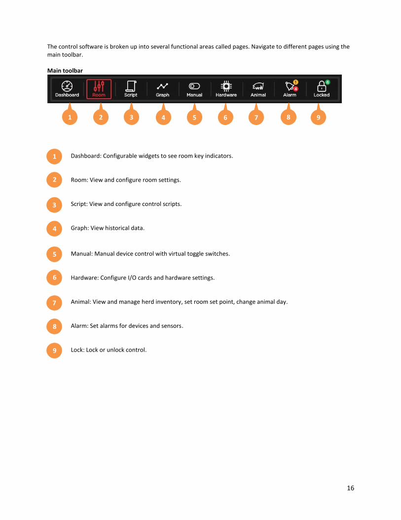
The control software is broken up into several functional areas called pages. Navigate to different pages using the
main toolbar.
Main toolbar
Dashboard: Configurable widgets to see room key indicators.
Room: View and configure room settings.
Script: View and configure control scripts.
Graph: View historical data.
Manual: Manual device control with virtual toggle switches.
Hardware: Configure I/O cards and hardware settings.
Animal: View and manage herd inventory, set room set point, change animal day.
Alarm: Set alarms for devices and sensors .
Lock: Lock or unlock control.
1
2
3
4
5
6
7
8
9
1
2
3
4
5
6
7
8
9

17
4.1 Touch Screen Input Methods
Virtual keyboard
The control system is touch screen based and some areas of the control require the use of a keyboard. The
keyboard will automatically appear when the user presses on a text field.
Virtual keypad
Value field inputs will bring up a numeric keypad. Some value fields have a defined range and the calculator will
display the min and max values.

18
5.0 Control Configuration In the rooms tab, define one or multiple rooms for this control. Additional rooms can be added by clicking on the
Add New Program ① button. Rooms will automatically name sequentially. The user can click on an existing room
to enable editing options. Click the Pencil ② icon to change a room name or define room attributes. To delete a
room click on the Trash icon ③, a warning will confirm this action.
The edit room pop-up, accessed from the Pencil ② icon, allows the room name to be configured as well as the
room dimensions. Room dimensions are used in room wind-chill calculations.
1
2 3

19
Edit room pop-up:

20
5.1 File Settings The control operates based on a configuration file. This configuration file can be backed up, reloaded, wrote over
and transferred to other controls. Use this screen to create a backup or reload a previously saved file.
Tip
Create seasonal programs (ex. Winter, Spring, Summer, and Fall) and use the save and load functions to easily
move between these unique programs.
Load settings can either be done as a full load or a smart load. A full load will download an entire configuration file.
A smart load retains the control name, serial number and room names. Use smart load when copying
configuration files from one control to another.
21
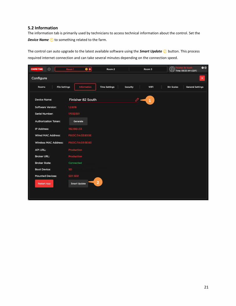
5.2 Information The information tab is primarily used by technicians to access technical information about the control. Set the
Device Name ① to something related to the farm.
The control can auto upgrade to the latest available software using the Smart Update ② button. This process
required internet connection and can take several minutes depending on the connection speed.
1
2
22
5.3 Time Settings
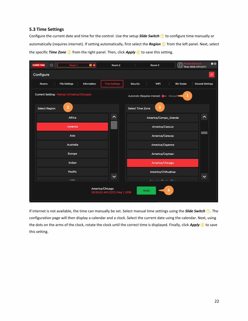
Configure the current date and time for the control. Use the setup Slide Switch ① to configure time manually or
automatically (requires internet). If setting automatically, first select the Region ② from the left panel. Next, select
the specific Time Zone ③ from the right panel. Then, click Apply ④ to save this setting.
If internet is not available, the time can manually be set. Select manual time settings using the Slide Switch ①. The
configuration page will then display a calendar and a clock. Select the current date using the calendar. Next, using
the dots on the arms of the clock, rotate the clock until the correct time is displayed. Finally, click Apply ④ to save
this setting.
4
2 3
1

23
5.4 Security The control can be configured to different security levels enabling the primary user to restrict access and limit
changes to secondary users.
Settings:
- Autolock: Returns the control to the Default lock level when the screen saver turns on.
- Alarm System: Enable the alarm system.
- Remote Control: Enable remote control of the system using the phone app.
- Default Lock Level: The lock level used when no higher level user is logged in.
Local Users: Setup access codes for specific permission levels when not using security groups (requires
internet).
Default Permissions: Descriptions of what permissions are allowed at each lock level. The default level 6
PIN is 0000 and can be edited from the security tab.
Login History: View the historical user login list.
2
3
4
1
2
3
4
1
24
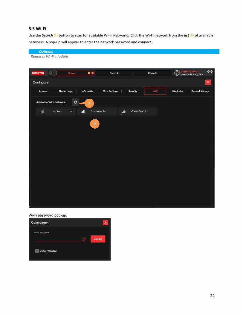
5.5 Wi-Fi
Use the Search ① button to scan for available Wi-Fi Networks. Click the Wi-Fi network from the list ② of available
networks. A pop-up will appear to enter the network password and connect.
Optional
Requires Wi-Fi module.
Wi-Fi password pop-up:
2
1

25
5.6 Bin Scales Ensure the BinTrac system is successfully on the network and operational. Once confirmed connect to the BinTrac
using the IP address of the BinTrac and click the Connect ① button. Click Enable ② for each bin that pertains to
this control. Once a bin is enabled, select which room the bin belongs to using the Combo box ③. Lastly, define a
Bin Name ④ which will be used throughout the control.
Optional
Requires BinTrac system.
1
2 3 4

26
5.7 General Settings
Screen Saver: Change the screen saver timeout.
Bandwidth Reduction: Reduce screen update rate for reduced bandwidth usage over VNC.
Device State Over Block: Show device state bubble over block on room page.
Location Information: Set the location of the control with zip-code or latitude and longitude coordinates.
These settings are how the control calculates the sunrise and sunset times.
1
2
3
4
1
2
3
4

27
6.0 Dashboard Page The dashboard page shows the user valuable information from the control. Widgets can be configured and placed
on the dashboard based on the user requirements. Each room has its own dashboard page and each can be
configured uniquely.
Widgets are added by pressing the Add Widget ① button. This will bring up a list of available widgets. Each widget
will display the amount of grid spaces required to display the widget. A total of 64 grid spaces are available per
room.
Tip
Place the large widgets first.
2
1

28
Add Widget: Click to display list of available widgets. Once the list is displayed, click and drag the widget
to an available location on the widget grid. While add widget is enabled, a widget can be moved on the
grid.
1
29
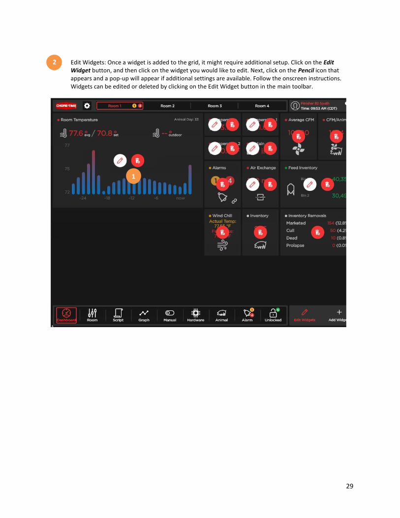
Edit Widgets: Once a widget is added to the grid, it might require additional setup. Click on the Edit
Widget button, and then click on the widget you would like to edit. Next, click on the Pencil icon that
appears and a pop-up will appear if additional settings are available. Follow the onscreen instructions.
Widgets can be edited or deleted by clicking on the Edit Widget button in the main toolbar.
2
1

30
7.0 Room Page The room page is the primary page for accessing and configuring devices. The room page is broken into two main
panels: Block Panel ① and Device and Sensor Panel ②.
1
2

31
Block Panel
The block panel consists of temperature based blocks which indicate when a device will operate. The block consists
of several elements: block minimum and maximum operating range, operating state at the minimum and
maximum temperatures, current block temperature and the block set point. The color of the block indicates if the
block is a heating or cooling device.
1
32
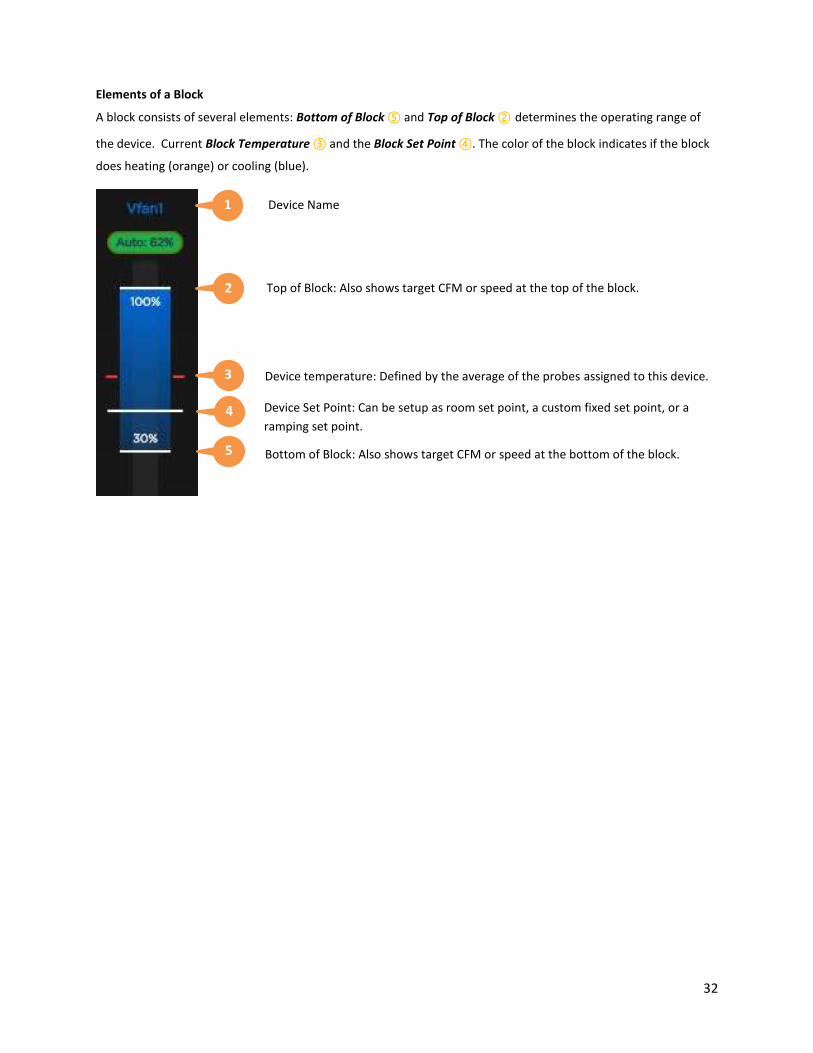
Elements of a Block
A block consists of several elements: Bottom of Block ⑤ and Top of Block ② determines the operating range of
the device. Current Block Temperature ③ and the Block Set Point ④. The color of the block indicates if the block
does heating (orange) or cooling (blue).
1
2
3
4
5
Device Name
Top of Block: Also shows target CFM or speed at the top of the block.
Device temperature: Defined by the average of the probes assigned to this device.
Device Set Point: Can be setup as room set point, a custom fixed set point, or a
ramping set point.
Bottom of Block: Also shows target CFM or speed at the bottom of the block.

33
Device and Sensor Panel
Device & Sensor Panel: This panel lists the devices and sensors assigned to the room. If a device or sensor is
selected from the panel by touching it, additional options will appear. By default, the device list is shown. To view
sensors, touch on the sensors icon at the top of this panel to view the sensor list.
2

34
Device and Sensor Panel: Compact Status
Within the device and sensors panel you see a list of items, these items are referred to a compact statuses. If you
click on a compact status if will expand to offer some links specific to this device or sensor. Below is an example of
a compact status for an exhaust fan. Image below from Device and Sensor panel.
Information: Load run time and usage data.
Device Configuration: Device operation
settings.
Graph: Load the graph data for this device.
Compact Status: Not selected.
Compact Status: Selected.
4
1
2
3
1
2
3
4
5
5
35
7.1 Device configuration Types There are three different types of device configurations: Block – Operate a heating or cooling device using a temperature block. Detailed in section 7.2 & 7.3.
Fan Group – Operate a group of fans from a block. Detailed in section 7.4.
Scheduled Device – Operate a device based on animal day and time. Detailed in section 7.5.
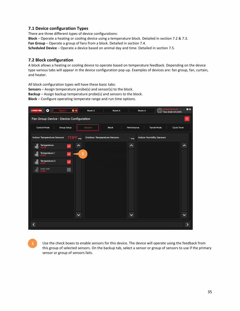
7.2 Block configuration A block allows a heating or cooling device to operate based on temperature feedback. Depending on the device
type various tabs will appear in the device configuration pop-up. Examples of devices are: fan group, fan, curtain,
and heater.
All block configuration types will have these basic tabs:
Sensors – Assign temperature probe(s) and sensor(s) to the block.
Backup – Assign backup temperature probe(s) and sensors to the block.
Block – Configure operating temperate range and run time options.
Use the check boxes to enable sensors for this device. The device will operate using the feedback from
this group of selected sensors. On the backup tab, select a sensor or group of sensors to use if the primary
sensor or group of sensors fails.
1
1

36
7.3 Block Under the Block tab the operating parameters for the device are configured. The device will run based off of the
temperature feedback from the probes assigned on the Sensors tab or in the case of a sensor failure, the Backup
tab.
A block is a temperature range defined by two values: Block Height ① and Offset from Set Point ②.
Block Height: Operating range of the block.
Offset from Set point: Degrees from the set point to the bottom of the block.
Set Point: Set point can be defined in one of three modes:
- Room: Uses the set point of the room.
- Custom: A fixed set point that is not tied to the room and only applies to this block.
- Ramping: Ramp based on user defined points by animal day.
Extensions: Extend the block to infinitely higher or lower temperatures .
Configuration Type: Set the operation of the block as normal or differential.
1
2
3
4
1
2
3
4
5
5

37
Device Ramping Set Point
Below is an example of a ramping device set point. Multiple temperature points can be defined by animal day. The
control will adjust the set point for the device as the room animal day increases. The temperature will ramp
linearly between defined days.
Set Point Mode.
Inputs to define ramp points by animal day and target temperature.
Add user defined point.
User defined ramp points, ordered by animal day.
Tip
Tap an existing ramp point to edit.
3
1
2
4
1
2
3
4

38
Device Cycle Timer
Below is an example of a cycle timer which can be applied to a block to reduce minimum ventilation. The cycle
timer will adjust its on-time based on the temperature feedback of the block.
Cycle Time: Duration of one full cycle (on-time plus off-time).
Low temperature percentage on: percent of the cycle the device is on at the bottom of the block.
High temperature percentage on: percent of the cycle the device is on at the top of the block.
Note
Some devices have additional tabs under the device configuration pop-up. These tabs are specific to the
functions of this type of device.
5
6
7
6
7
5

39
7.4 Device Configuration – Fan Group Fan group is a virtual device that operates from a single block. This group of fans is controlled by the software and
continually operates the group of fans at its most efficient state to achieve the temperature, pressure or CFM
requested from the block.
Fan Group – Control Mode
Name: Define name for fan group.
Mode Selection: Define if the group will operate based on temperature or pressure feedback. Depending
on mode type, different tabs will become available in the fan group pop-up.
Slew Rate: Maximum CFM change in defined period.
1
2
3
1
2
3

40
Fan Group – Group
Using the Group tab found in the fan group device configuration pop-up, define the group of fans. The left column
lists ① the available fans. The right column lists ② the fans in the group. Add and remove devices from the fan
group using the Left/Right Arrow keys ③. Set the fan priority within the group using the up/down keys ④.
Available fans which can be assigned to the group.
List of fans assigned to the fan group.
Add or remove a fan from the group.
Change priority of fan within the group. Higher priority fans will be selected to run first.
1
2
3
4
1 2 3 4

41
Fan Group – Performance
Using the Performance tab found in the fan group device configuration pop up, configure each fans operating
characteristics.
Requested & Actual CFM: Displays the CFM requested from the block and the fan delivered CFM.
Minimum Speed: Minimum fan speed the fan group can operate this device.
Current & Max CFM: Displays the current CFM output vs the full speed CFM of the device.
1
2
3
1
2 3

42
7.5 Device Configuration – Scheduled Devices (Feed Motor, Light, Clock)
A schedule based device configuration operates based off a user defined schedule and animal day. The schedule
will determine which program to run based on the animal day. It will then check if the schedule is allowed to run
based on the weekday parameter. If allowed, it will operate the device during the scheduled run time(s).
Programs: List of program schedules. The controller will progress through the schedules based on animal
day. Add new programs by clicking on the Pencil icon. Delete a program by click on the Trash icon.
Program Detail: Define the program name and starting animal day. For advanced programs, specific days
of the week for this program to operate can be set.
Scheduled Times: Click on the pencil icon to add a new scheduled run time. Advanced programs can
operate based on sunrise and sunset accessed through the Sun icon.
Tip
Once two schedule times have been configured, the control will see a pattern of start, stop and run times. Use
the duplicate key to replicate this pattern.
1 2 3
1
2
3

43
Schedule Based Devices – Light
A light device schedule varies some from the above start and stop time schedule. In a lighting device, the schedule
uses start times and light intensity. The controller will operate the light based on the lighting intensity defined at a
start time. It will then linearly ramp towards the next lighting intensity. A light schedule can also run based on
sunrise and sunset events.
Time: Time when event happens.
Percentage: Light intensity at event time.
1
2
1 2

44
Schedule Based Devices – Feed Motor Timers
The feed motor device has integrated Max Run ① and Max Idle ② timers. When these timers expire, they can be
configured to generate alarms through the alarm system.
Max Run Timer: Time device can operate continuously with amps before being disabled.
Max Idle Timer: Time device has no amps during a schedule run time.
1
2
1 2

45
8.0 Script
Scripts can be accessed under the Script icon in the main toolbar. Scripts are user defined conditional statements
that can operate a device based on if/then logic. If multiple scripts are trying to control a device with conflicting
signals, the script in the highest priority group and the highest priority script in that group will prevail.
Script Summary: All available scripts. Can be filtered by group from the Script Group ② panel.
Script Groups: Lists all groups of scripts and the scripts within the group.
Add Script: Open pop-up to create new script.
Script Priority: Increase of decrease the priority of a script within a group.
Tip
False statements are red. True statements are green.
1
2
3
2
3
4
4
1
4

46
8.1 Script Editor
The second step in creating a script is to define the Conditional Statement ③. Complete each unknown box in the
order as you would read the script. When you highlight an unknown box, the right panel will List ④ the available
options for this field. Most fields require the selection of two components. For example, if selecting the device
Curtain you would then need to select an attribute of the curtain, such as Length Open.
Multiple conditions can be combined using and/or logic. Once all conditions in the IF statement becomes true, the
THEN section of the statement will activate.
Script Name: Define a name for the script which will appear in the script summary page.
Script Groups: Assign the script to an existing group or create a new group. Toggle between new scripts
and existing scripts using the Pencil icon.
Conditional Statement: Define all script unknowns until the script is logically complete.
Script Variable: List of script variables.
21
4
1
2
3
4
3

47
9.0 Graphs
Graphs can be accessed under the Graph icon in the main toolbar. Historical information can be viewed using the
graphing tool and overlaid upon multiple devices and sensors.
In the right hand panel graph options are grouped by devices and sensor types. Different items are stored under
these groups. Expand a group and highlight one or more items to load onto the graph panel to the left.
Graph Panel: Displays data based on selected devices and sensors for the defined time period.
Device and Sensor Panel: List of items that can be graphed.
Time Zoom: Define the length of time displayed on the graph (horizontal axis).
Time Move: Change the time frame displayed on the graph with large or small steps. The center key will
undo the last change.
Tip
Use the bullseye to highlight a dataset. Touch and drag horizontally to zoom in.
1
2
3
4
1 2
4 3

48
10.0 Manual Mode
Manual control can be accessed under the Toggle Switch icon in the main toolbar. Virtual toggle switches are
available here to manually operate devices. By default, all devices are shown. Use the device type filter in the right
hand panel to view only devices of this type.
3-State Toggle
2-State Toggle
Variable Speed Toggle

49
11.0 Hardware
The hardware configuration of the control is represented virtually under the hardware icon in the main toolbar.
Virtual hardware appears automatically as new hardware is added. To setup a sensor or device click on the green
box in the virtual hardware. This will open a configuration screen specific to the card type.
Virtual Backplane: View installed hardware virtually.
Hardware Setup Panel: Configure card settings.
Delete: Remove card and all settings.
Update: Update firmware on card. The firmware version will appear on the card in red text in place of the
card name if a firmware update is available.
Tip
If an indicator bubble appears next to the Hardware icon in the main toolbar it means:
- Red: Shutdown current exceeded
- White: Card firmware update available
1
2
21
3
4
3
4

50
11.1 Hardware - Input Card
The input card setup defines which type of input is on each channel of the input card and which room the sensor
belongs to. Some input types will have additional configuration requirements. The first eight channels of the input
card can be setup as resistive or pulse type sensors. Below is an example of a temperate probe setup.
Name: Sensor name used throughout control.
Type: Define connected probe type.
Location: Indoor / outdoor.
Brand: Set sensor brand to match probe resistance curve.
Offset: To adjust for any skew due to probe location.
Room: Define what rooms probe will be used in
.
Note
Sensor types: Wind speed, Water meter, and Switch have additional options settings.
- Wind Speed: Scale defines how many pulses per hour for 1 MPH
- Water Meter: Scale defines how many pulses from the sensor per gallon of water
- Switch: Resting state defines if the switch is wired normally open (NO) or normally closed (NC)
1
2
3
4
1
2
3
4
5
6
5
6

51
The last two channels of the input card can be setup as 4-20mA sensors.
Name: Sensor name used throughout control.
Type: Define connected probe type.
Location: Indoor / outdoor.
Room: Define what rooms probe will be used in.
Note
Sensor types: Static Pressure, Pressure gauge, Current, Ammonia, C02, and Water level have additional
options settings.
- Static Pressure: Scale defines the full scale pressure in water column inches of the sensor
- Pressure Gauge: Scale defines the full scale pressure of the sensor
- Current: Scale defines the full scale amperage of the sensor
- Ammonia: Scale defines the full scale ammonia reading of the sensor
- C02: Scale defines the full scale C02 reading of the sensor
- Water Level: Scale defines the full scale water level reading of the sensor
1
2
3
4
1
2
3
4
52
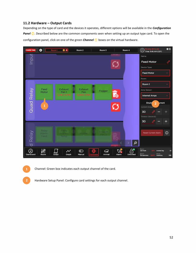
11.2 Hardware – Output Cards
Depending on the type of card and the devices it operates, different options will be available in the Configuration
Panel ②. Described below are the common components seen when setting up an output type card. To open the
configuration panel, click on one of the green Channel ① boxes on the virtual hardware.
Channel: Green box indicates each output channel of the card.
Hardware Setup Panel: Configure card settings for each output channel.
1 2
1
2

53
Hardware Setup Panel
Name: Device name used throughout control. Define
device type prior to naming.
Type: Define connected device type.
Room: Define what room device is located in.
Tunnel Fan: Threshold that control enters tunnel mode.
Require Amperage: Device must pull amps to be
considered in working condition. Otherwise the control
will bypass the fan for another fan in working condition.
Max CFM: Full speed fan capacity in CFM.
Shutdown Current: Maximum current draw before the
control shuts the channel down for protection. Requires
both a maximum current limit and duration this current
limit has to be exceeded.
Reset Current Alarm: Reset the shutdown current fault
condition.
Special case settings:
Minimum Speed: For variable speed devices, slowest
speed the device can operate without damaging the
hardware.
Invert Signal: For analog output devices, inverts the
output signal from full power at 10V to full power at 0V.
Surge Time: For variable speed devices, time the device
will operate at full power before going to a variable
speed.
Resting State: For alarm relay device, set non-fault state
of the alarm output.
1
2
3
4
1
2
3
4
5
6
7
5
6
7
8
8
9
10
11
12
9
10
11
12

54
11.3 Hardware – Curtain Cards
Curtain devices have special settings listed below:
Name: Device name used throughout control.
Type: Define curtain/inlet type.
Room: Define what room the device is located in.
Input Mode: Define card feedback sensor type.
Navigation Mode: Define the mode the curtain uses for
navigation.
Length: Define curtain/inlet travel length.
Minimum Natural Mode opening.
Fallback Set Point.
Full Open Time.
Full Close Time.
Hysteresis.
Shutdown Current.
1
2
3
4
5
6
7
8
9
10
11
1
2
3
4
5
6
7
8
9
10
11
12
12

55
12.0 Animal Page
Animal inventory and animal day based controls can be accessed under the Animal icon in the main toolbar. Inside
of the animal page there are multiple functional areas:
Inventory – Manage animal inventory.
Temperature Curve – Adjust the room temperature curve based on animal day.
Animal Day – Adjust the animal day.
12.1 Animal Inventory
Animal inventory data can be recorded in the control based on animal group. The basic process for recording data
goes as follows:
Add / Remove: Select the inventory action. This will update the addition/removal Reasons List (3).
Quantity: Define how many animals will be added or removed for this record.
Addition / Remove Reasons: Select the detailed reason of this transaction.
1
2
1
2
3
4
3

56
Record: Save this inventory record.
Animal Inventory – Settings
Group Settings: Pop-Up to configure group name and add a new animal group. The active animal group is
the most recently created group.
Reasons Settings: Pop-Up to configure custom removal reasons.
Inventory Journal: View inventory records for the group.
4
1
2
1
2
3
3

57
12.2 Animal Day
Animal Day: Manually set animal day. Once set, animal day will automatically increment each day.
New Group: Sets animal day to zero. All devices set to automatic.
Pause Animal Day: Pauses animal day from incrementing.
Clean Mode: Disables alarm generation.
1
2
3
2
3
4
1
4

58
12.3 Temperature Curve
The room set point can ramp based on a temperature curve. To enable this feature, check the Enable Temperature
Curve ① box.
Enable Temperature Curve: Room set point comes from temperature curve if enabled. If disabled, room
set point is set manually from the room page.
Inputs to define ramp points by animal day and target temperature.
User defined ramp points, ordered by animal day.
Tip
Tap an existing ramp point to edit.
Tip
The room set point cannot be adjusted from the room page while a temperature curve is active.
1
2
3
1
2
3
59
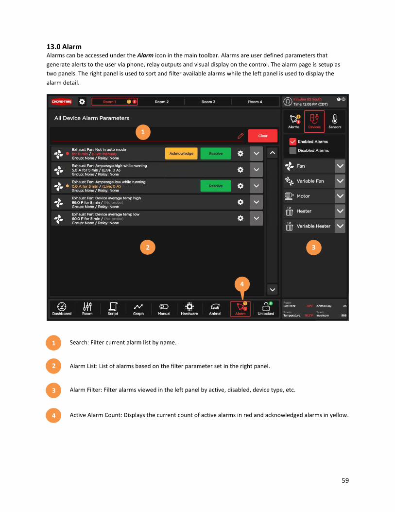
13.0 Alarm
Alarms can be accessed under the Alarm icon in the main toolbar. Alarms are user defined parameters that
generate alerts to the user via phone, relay outputs and visual display on the control. The alarm page is setup as
two panels. The right panel is used to sort and filter available alarms while the left panel is used to display the
alarm detail.
Search: Filter current alarm list by name.
Alarm List: List of alarms based on the filter parameter set in the right panel.
Alarm Filter: Filter alarms viewed in the left panel by active, disabled, device type, etc.
Active Alarm Count: Displays the current count of active alarms in red and acknowledged alarms in yellow.
1
2
3
4
1
3
4
2

60
13.1 Alarm Settings
Each device and sensor has a unique list of available alarms. Click the Gear ③ icon of an alarm to configure the
alarm settings.
The alarm header (below) provides a summary of the alarm settings. If the alarm is active, it will also display the
Acknowledge ① and Resolve ② buttons depending on the current alarm state.
When the alarm setup is access through the Gear ③ icon, the settings will appear. The first section relates to the
alarm thresholds. The Alarm Limit ④ is the amount this condition has to be exceeded to be in an alarm state. The
Trip Time ⑤ is how long the Alarm Limit ④ must be exceeded before issuing an alarm. Additionally, users can
Manually Fire ⑥ an alarm to test the alarm outputs. To enable or disable this alarm, set the enable slide Switch ⑦
to On or Off.
The second setup section sets the values used for the alarm system for resolving and acknowledging alarms. Bump
Time ⑧ is the amount of time a user has to acknowledge an alarm before the alarm will be sent to another user in
an alarm group. Acknowledge Time ⑨ is the amount of time a user has to resolve an acknowledged alarm before
it returns to an active alarm. Auto Resolve ⑩ will allow the controller to automatically resolve the alarm if the
alarm condition has gone away.
3 1 2
4 5 6 7
8 9 10
61
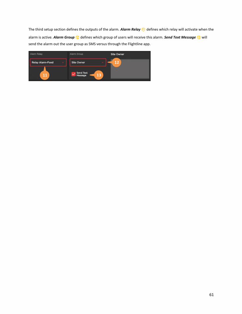
The third setup section defines the outputs of the alarm. Alarm Relay ⑪ defines which relay will activate when the
alarm is active. Alarm Group ⑫ defines which group of users will receive this alarm. Send Text Message ⑬ will
send the alarm out the user group as SMS versus through the Flightline app.
11
12
13
62
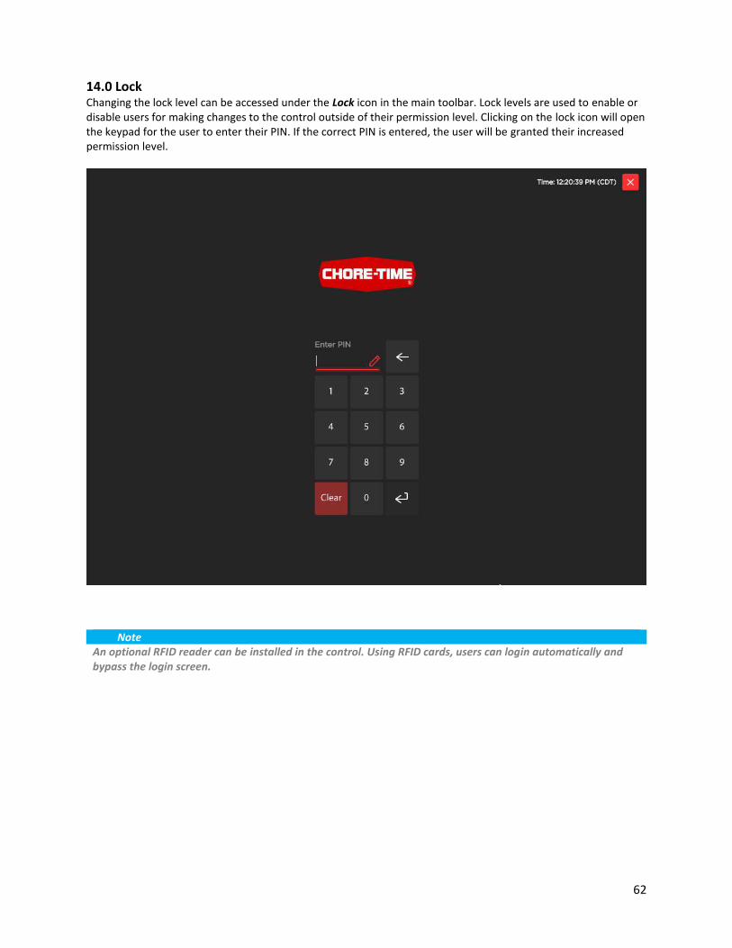
14.0 Lock Changing the lock level can be accessed under the Lock icon in the main toolbar. Lock levels are used to enable or
disable users for making changes to the control outside of their permission level. Clicking on the lock icon will open
the keypad for the user to enter their PIN. If the correct PIN is entered, the user will be granted their increased
permission level.
Note
An optional RFID reader can be installed in the control. Using RFID cards, users can login automatically and
bypass the login screen.
63
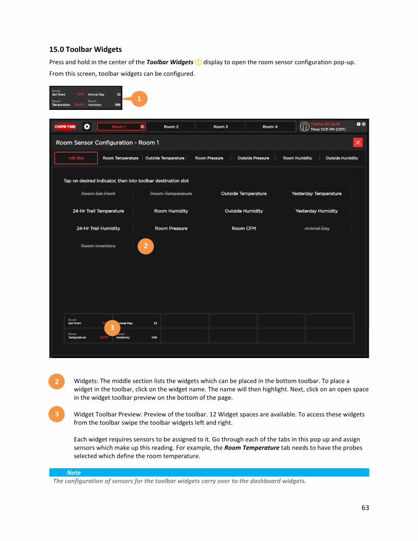
15.0 Toolbar Widgets
Press and hold in the center of the Toolbar Widgets ① display to open the room sensor configuration pop-up.
From this screen, toolbar widgets can be configured.
Widgets: The middle section lists the widgets which can be placed in the bottom toolbar. To place a
widget in the toolbar, click on the widget name. The name will then highlight. Next, click on an open space
in the widget toolbar preview on the bottom of the page.
Widget Toolbar Preview: Preview of the toolbar. 12 Widget spaces are available. To access these widgets
from the toolbar swipe the toolbar widgets left and right.
Each widget requires sensors to be assigned to it. Go through each of the tabs in this pop up and assign
sensors which make up this reading. For example, the Room Temperature tab needs to have the probes
selected which define the room temperature.
Note
The configuration of sensors for the toolbar widgets carry over to the dashboard widgets.
2
3
2
3
1