Embed Size (px)
Citation preview
Installation
P.O. Box 309Menomonee Falls, WI 53052 USA
800 BRADLEY (800 272 3539)+1 262 251 6000bradleycorp.com
WF2500 Series Terreon Classic
WF2600 Series Terrazzo
WF2700 Series Stainless Steel
WF2800 Series Bradstone
WF3200 Series Terreon Deep Bowl
TDB3100 Series Terreon Deep Bowl
WF3203
215-1833-10 Rev. A; ECN 17-00-006B© 2017 BradleyPage 1 of 2 11/21/2017
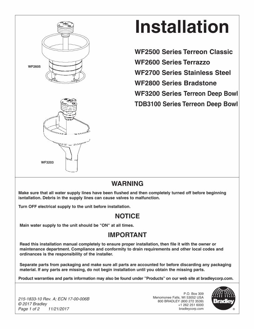
WF2605
WARNINGMake sure that all water supply lines have been flushed and then completely turned off before beginning isntallation. Debris in the supply lines can cause valves to malfunction.
Turn OFF electrical supply to the unit before installation.
NOTICEMain water supply to the unit should be "ON" at all times.
IMPORTANTRead this installation manual completely to ensure proper installation, then file it with the owner or maintenance department. Compliance and conformity to drain requirements and other local codes and ordinances is the responsibility of the installer.
Separate parts from packaging and make sure all parts are accounted for before discarding any packaging material. If any parts are missing, do not begin installation until you obtain the missing parts.
Product warranties and parts information may also be found under ”Products” on our web site at bradleycorp.com.
Cleaning and Maintenance WF2500, WF2600, WF2700, WF2800, WF3200, TDB3100 Series
P.O. Box 309 • Menomonee Falls, WI 53052-0309 • 1 800 BRADLEY • 262 251 6000 • bradleycorp.com
2 of 3 12/19/2017 Bradley • 215-1832-10 Rev. A: ECN 17-00-006B
Cleaning and Maintenance for Terreon®
Material Description: Terreon is a densified solid surface material composed of bio based resin and is resistant to chemicals, stains, burns and impact. Surface can be easily repaired with everyday cleansers or fine grit abrasives. Because Terreon is a unique cast material, its aggregate flow and distribution, and shades of color can vary from product to product creating natural characteristics.
Routine Cleaning: For regular cleaning, use mild neutral base cleaners.
Stubborn Stains: Remove tough stains with Soft-Scrub® and a green Scotch-Brite® pad or lightly sand in a circular motion with 240 grit wet/dry sandpaper. The finish can then be renewed with a maroon Scotch-Brite pad.
Scratches: Remove scratches with a green Scotch-Brite pad. The finish can then be renewed with a maroon Scotch-Brite pad.
Hard Water Deposits: Remove hard water deposits with a mild solution of vinegar and water. Always rinse the unit thoroughly after cleaning.
Restoring the surface: Use Hope’s® Perfect Countertop to refresh and protect the Terreon Solid Surface material. Dark Terreon colors may require additional care and maintenance. For complete instructions on this additional maintenance, visit bradleycorp.com.
Repair Kits: Terreon repair kits are available. Contact your Bradley representative or distributor for part numbers and pricing. Repair kits are made to order and have a shelf life of 30 days.
NOTICE! Do not use strong acid or alkaline chemicals and cleaners to clean Terreon. If these chemicals come in contact with the surface, wipe them off immediately and rinse with soapy water. Avoid contact with harsh chemicals such as paint remover, bleach, acetone, etc. Avoid contact with hot pans and objects.
Cleaning and Maintenance for Stainless SteelMaterial Description: Stainless steel is extremely durable, and maintenance is simple and inexpensive. Proper care, particularly under corrosive conditions, is essential. Always start with the simplest solution and work your way toward the more complicated.
Routine cleaning: Daily or as often as needed use a solution of warm water and soap, detergent, or ammonia. Apply the cleaning solution per the manufacturer's instructions and always use a soft cloth or sponge to avoid damaging the finish.
Stubborn Stains: To remove stains from stainless steel use a stainless steel cleaner and polish such as Ball® stainless steel cleaner or a soft abrasive. Always follow the manufacturer's instructions and apply in the same direction as the polish lines.
NOTICE! Never use ordinary steel wool or steel brushes on stainless steel. Always use stainless steel wool or stainless steel brushes.
Fingerprints and Smears: To remove fingerprints or smears use a high quality stainless steel cleaner and polish in accordance with the manufacturer's instructions. Many of these products leave a protective coating that helps prevent future smears and fingerprints.
Grease and Oil: To remove grease and oil use a quality commercial detergent or caustic cleaner. Apply in accordance to the manufacturer's instructions and in the direction of the polish lines.
Precautions: Avoid prolonged contact with chlorides (bleaches, salts), bromides (sanitizing agents), thiocyanates (pesticides, photography chemicals, and some foods), and iodides on stainless steel equipment, especially if acid conditions exist.
NOTICE! Do not permit salty solutions to evaporate and dry on stainless steel.The appearance of rust streaks on stainless steel leads to the belief that the stainless steel is rusting. Look for the actual source of the rust in some iron or steel particles which may be touching, but not actually a part of the stainless steel structure.
NOTICE! Strongly acidic or caustic cleaners may attack the steel causing a reddish film to appear. The use of these cleaners should be avoided.
Brand NamesUse of brand names is intended only to indicate a type of cleaner. This does not constitute an endorsement, nor does the omission of any brand name cleaner imply inadequacy. Many products named are regional in distribution, and can be found in local supermarkets, department and hardware stores, or through your cleaning service. It is emphasized that all products should be used in strict accordance with package instructions.
Cleaning and Maintenance WF2500, WF2600, WF2700, WF2800, WF3200, TDB3100 Series
P.O. Box 309 • Menomonee Falls, WI 53052-0309 • 1 800 BRADLEY • 262 251 6000 • bradleycorp.com
3 of 3 12/19/2017 Bradley • 215-1832-10 Rev. A: ECN 17-00-006B
Cleaning and Maintenance for TerrazzoMaterial Description: Terrazzo is a mosaic-looking natural stone and concrete material polished to a high gloss and sealed with clear polyurethane resin for long lasting beauty. Terrazzo is precast and composed of 85% stone and 15% binder with steel reinforcing rods cast into the bowl.
Routine Cleaning: Clean daily or as often as conditions require with any standard detergent, warm water and a soft cloth.
Stubborn Stains: If stains have permeated the surface of the terrazzo, follow instructions for restoring the surface listed below.
Restoring the surface: Use paint stripper to remove the existing polyurethane (it is important to remove all of the old polyurethane to ensure a high quality finish). Then use light grit sand paper to remove any stubborn staines that have permeated the surface. Clean and thoroughly dry the bowl. Then apply 2 to 3 coats of polyurethane to the terrazzo in accordance with the manufacturer's instructions. Allow the polyurethane to dry completely per the manufacturer's recommendations before turning on the water.
NOTICE! If the bowl is not completely dry before applying the polyurethane, the polyurethane will not adhere to the surface.
NOTICE! Make sure the surface is complete covered with polyurethane to prevent water from penetrating the surface and damaging the terrazzo.
Repair Kits: Terrazzo repair kits are available. Contact your Bradley representative or distributor for part numbers and pricing.
NOTICE! Do not place acid or alkaline solutions (floor stripper or drain cleaners) into the terrazzo bowl or use them to clean the bowl. If these solutions come into contact with the terrazzo, rinse the bowl immediately with water and inspect for damage. If damage has occurred, follow the directions for restoring the surface. If bowl begins to haze, it is usually a sign that the terrazzo has come into contact with an acid or alkaline chemical or has been exposed to UV radiation. To repair this condition, follow the instructions for restoring the surface.
Cleaning and Maintenance for BradstoneMaterial Description: Bradstone is an extremely durable plastic material made of reinforced thermosetting polyester resins, finely ground inorganic fillers and fade resistant pigments. Bradstone is impervious to most chemicals and stains.
Routine Cleaning: Soap and dirt accumulations should be washed off with detergent cleaners. Abrasive and caustic cleaners are not recommended. An occasional waxing with automotive wax will make future cleaning even easier.
1 of 11 1/29/2018 Bradley • 215-1833-3 Rev. A: ECN 17-00-021A
Bowl and Pedestal Assembly (Stainless Steel & Terrazzo) WF2603, WF2604, WF2703, WF2704
P.O. Box 309 • Menomonee Falls, WI 53052-0309 • 1 800 BRADLEY • 262 251 6000 • bradleycorp.com
This document describes installation of washfountain bowl and pedestal only. Some optional equipment and accessories are shown for clarity. For activation, optional equipment and accessory installation, see installation documents included with those parts.
Supplies Required by Installer• (6) 1/2" lag bolts, screws or other fasteners to anchor washfountain pedestal
• 1" hot and cold water or tempered supply lines and fittings (see activation instructions)
• Reducing fittings and 1/2" nom. copper tubing supply lines for types with supplies from above (see activation instructions)
• Standard P-trap (vented trap supplied by Bradley when required)
• 2" drain lines and fittings (see activation instructions)
• 1-1/2" vent pipe on types vented through washfountain column
• Pipe sealant and plumber's putty
Before installation of bowl and pedestal assemblies, review all included instructions. Some options may require additional steps during the bowl and pedestal installation process.
Supply lines for one or two washfountains should be 1"; for three washfountains 1-1/4"; for more than three washfountains, pipe size should increase proportionally. Vent pipe to be 1-1/2" on models vented through washfountain.
Valving installations for Classic washfountains require rigid plumbing installation and connections to ensure proper operation and support of the valve assemblies, especially for foot control activated washfountains. Do not use flexible supply hoses unless specified in your activation instruction documentation and supplied with your washfountain.
2 of 11 1/29/2018 Bradley • 215-1833-3 Rev. A: ECN 17-00-021A
Bowl and Pedestal Assembly (Stainless Steel & Terrazzo) WF2603, WF2604, WF2703, WF2704
P.O. Box 309 • Menomonee Falls, WI 53052-0309 • 1 800 BRADLEY • 262 251 6000 • bradleycorp.com
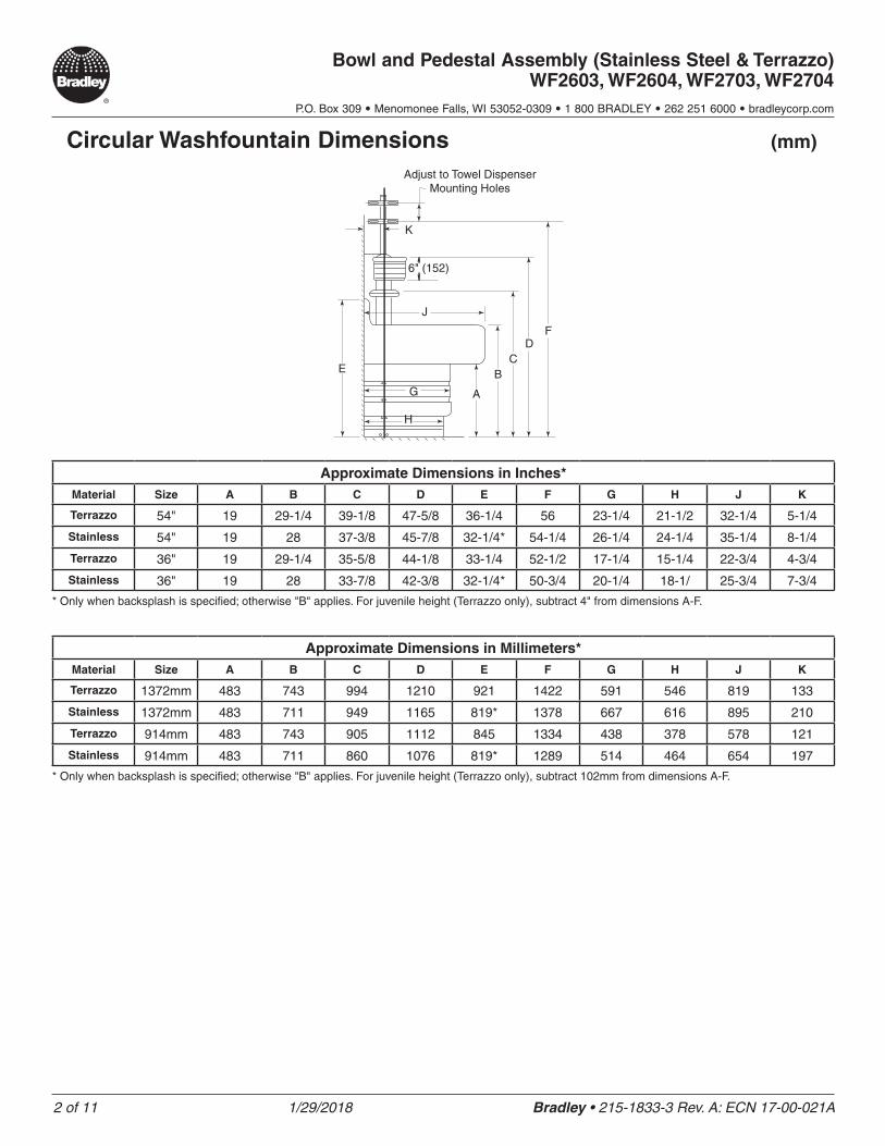
Circular Washfountain Dimensions
Adjust to Towel Dispenser Mounting Holes
K
(mm)
6" (152)
J
G
H
E
A
BC
DF
Approximate Dimensions in Inches*Material Size A B C D E F G H J K
Terrazzo 54" 19 29-1/4 39-1/8 47-5/8 36-1/4 56 23-1/4 21-1/2 32-1/4 5-1/4
Stainless 54" 19 28 37-3/8 45-7/8 32-1/4* 54-1/4 26-1/4 24-1/4 35-1/4 8-1/4
Terrazzo 36" 19 29-1/4 35-5/8 44-1/8 33-1/4 52-1/2 17-1/4 15-1/4 22-3/4 4-3/4
Stainless 36" 19 28 33-7/8 42-3/8 32-1/4* 50-3/4 20-1/4 18-1/ 25-3/4 7-3/4
* Only when backsplash is specified; otherwise "B" applies. For juvenile height (Terrazzo only), subtract 4" from dimensions A-F.
Approximate Dimensions in Millimeters*Material Size A B C D E F G H J K
Terrazzo 1372mm 483 743 994 1210 921 1422 591 546 819 133
Stainless 1372mm 483 711 949 1165 819* 1378 667 616 895 210
Terrazzo 914mm 483 743 905 1112 845 1334 438 378 578 121
Stainless 914mm 483 711 860 1076 819* 1289 514 464 654 197
* Only when backsplash is specified; otherwise "B" applies. For juvenile height (Terrazzo only), subtract 102mm from dimensions A-F.
3 of 11 1/29/2018 Bradley • 215-1833-3 Rev. A: ECN 17-00-021A
Bowl and Pedestal Assembly (Stainless Steel & Terrazzo) WF2603, WF2604, WF2703, WF2704
P.O. Box 309 • Menomonee Falls, WI 53052-0309 • 1 800 BRADLEY • 262 251 6000 • bradleycorp.com
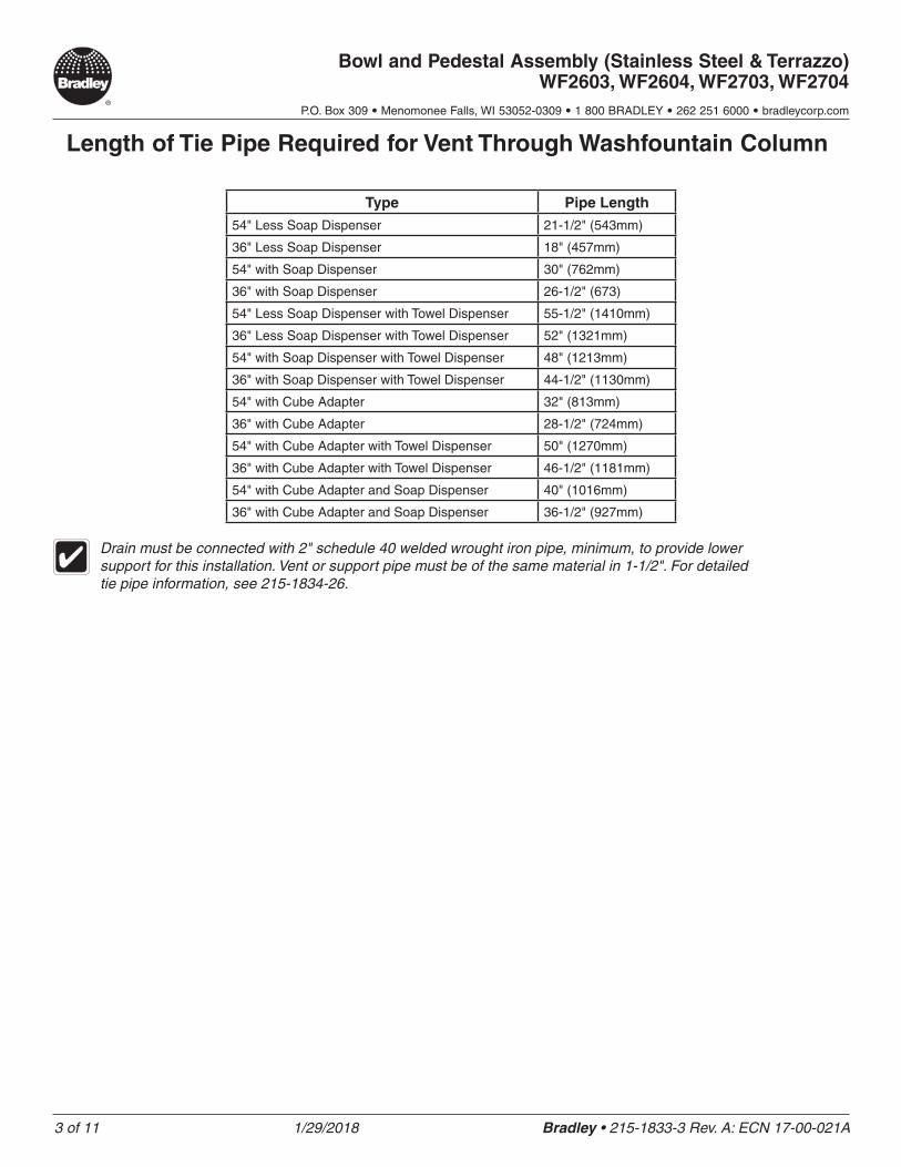
Length of Tie Pipe Required for Vent Through Washfountain Column
Type Pipe Length
54" Less Soap Dispenser 21-1/2" (543mm)
36" Less Soap Dispenser 18" (457mm)
54" with Soap Dispenser 30" (762mm)
36" with Soap Dispenser 26-1/2" (673)
54" Less Soap Dispenser with Towel Dispenser 55-1/2" (1410mm)
36" Less Soap Dispenser with Towel Dispenser 52" (1321mm)
54" with Soap Dispenser with Towel Dispenser 48" (1213mm)
36" with Soap Dispenser with Towel Dispenser 44-1/2" (1130mm)
54" with Cube Adapter 32" (813mm)
36" with Cube Adapter 28-1/2" (724mm)
54" with Cube Adapter with Towel Dispenser 50" (1270mm)
36" with Cube Adapter with Towel Dispenser 46-1/2" (1181mm)
54" with Cube Adapter and Soap Dispenser 40" (1016mm)
36" with Cube Adapter and Soap Dispenser 36-1/2" (927mm)
Drain must be connected with 2" schedule 40 welded wrought iron pipe, minimum, to provide lower support for this installation. Vent or support pipe must be of the same material in 1-1/2". For detailed tie pipe information, see 215-1834-26.
4 of 11 1/29/2018 Bradley • 215-1833-3 Rev. A: ECN 17-00-021A
Bowl and Pedestal Assembly (Stainless Steel & Terrazzo) WF2603, WF2604, WF2703, WF2704
P.O. Box 309 • Menomonee Falls, WI 53052-0309 • 1 800 BRADLEY • 262 251 6000 • bradleycorp.com
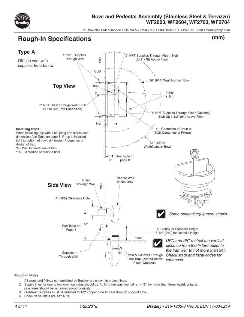
(mm)Rough-In Specifications
Type A
Off-line vent with supplies from below
1" NPT Supplies Through Wall
Trap
36" (914) Washfountain Bowl
2" NPT Supplies Through Floor: Stub Up 3" (76) Above Floor
Cold
Hot
2" NPT Drain Through Wall (Stub Out to Suit Trap Dimension)
54" (1372) Washfountain Bowl
Centerline of Drain to Centerline of Fixture
See Table on page 8
7-5/8" (194)
Installing Traps When installing trap with a coupling and nipple, see dimension A in Table on page 8. If trap is installed tight to bottom of bowl, dimension A depends on design of trap. *B - Wall to centerline of trap **A - Centerline of drain to floor
B*
4" (102)
1" NPT Supplies Through Floor (Optional) Stub Up 2-1/2" (64) Above Floor
Trap for Wall Outlet Only
Wal
lW
all
Drain Through Wall
4" (102) Clearance Hole
Top View
Side View
A**See Table on
Page 8
Supplies Through Wall Drain & Supplies Through
Floor Trap Located Below Floor (Optional)
12" (305) for Standard Height 8-1/4" (210) for Juvenile Height
Floor
Some optional equipment shown.
Rough-In Notes
1. All pipes and fittings not furnished by Bradley are shown in broken lines.2. Supply lines for one to two washfountains should be 1", for three washfountains 1-1/2"; for more than three washfountains,
pipe sizes should be increased proportionately.3. Overhead supplies must be reduced to 1/2" copper tube to pass through support tube.4. Check valve inlets are 1/2" NPT.
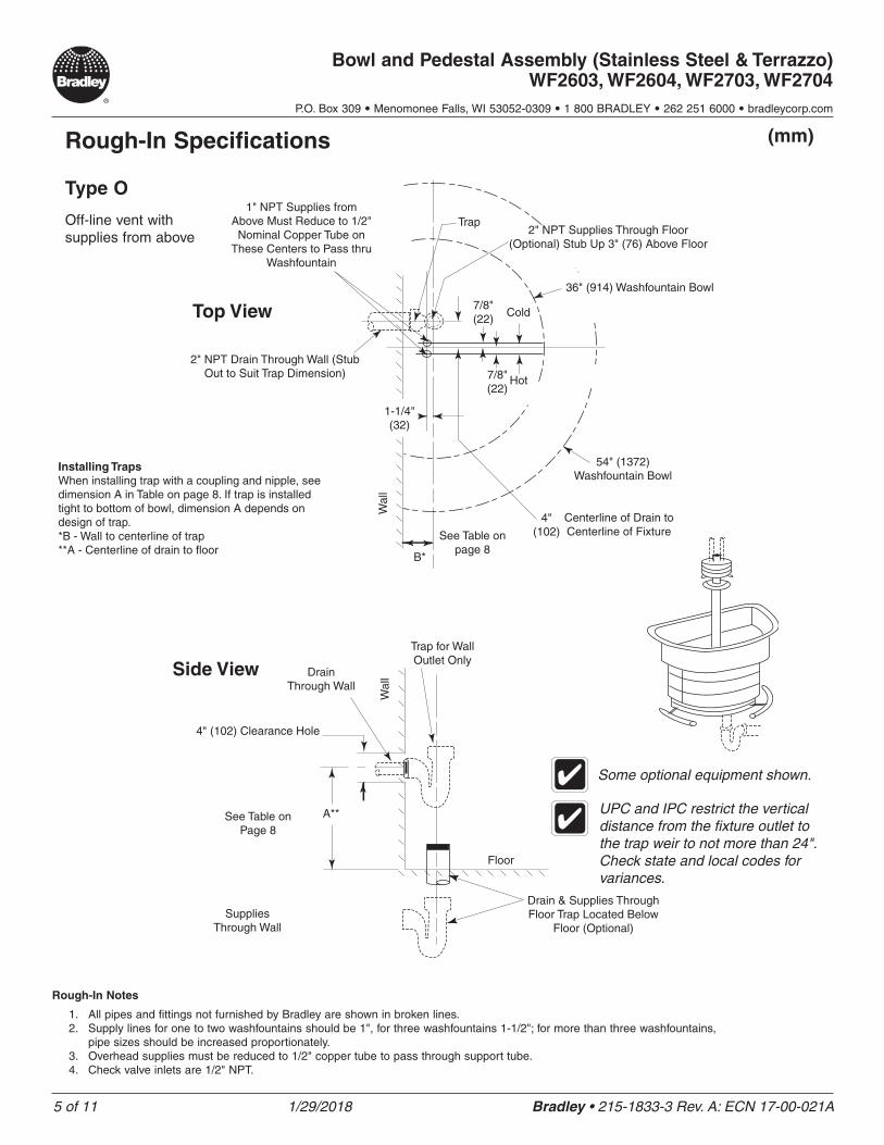
UPC and IPC restrict the vertical distance from the fixture outlet to the trap weir to not more than 24". Check state and local codes for variances.
5 of 11 1/29/2018 Bradley • 215-1833-3 Rev. A: ECN 17-00-021A
Bowl and Pedestal Assembly (Stainless Steel & Terrazzo) WF2603, WF2604, WF2703, WF2704
P.O. Box 309 • Menomonee Falls, WI 53052-0309 • 1 800 BRADLEY • 262 251 6000 • bradleycorp.com
Some optional equipment shown.
(mm)Rough-In Specifications
Type O
Off-line vent with supplies from above
1" NPT Supplies from Above Must Reduce to 1/2" Nominal Copper Tube on
These Centers to Pass thru Washfountain
Trap
36" (914) Washfountain Bowl
2" NPT Supplies Through Floor (Optional) Stub Up 3" (76) Above Floor
Cold
Hot
2" NPT Drain Through Wall (Stub Out to Suit Trap Dimension)
54" (1372) Washfountain Bowl
Centerline of Drain to Centerline of FixtureSee Table on
page 8
7/8" (22)
Installing Traps When installing trap with a coupling and nipple, see dimension A in Table on page 8. If trap is installed tight to bottom of bowl, dimension A depends on design of trap. *B - Wall to centerline of trap **A - Centerline of drain to floor
B*
4" (102)
Trap for Wall Outlet Only
Wal
lW
allDrain
Through Wall
4" (102) Clearance Hole
Top View
Side View
A**See Table on Page 8
Supplies Through Wall
Drain & Supplies Through Floor Trap Located Below
Floor (Optional)
Floor
Some optional equipment shown.
Rough-In Notes
1. All pipes and fittings not furnished by Bradley are shown in broken lines.2. Supply lines for one to two washfountains should be 1", for three washfountains 1-1/2"; for more than three washfountains,
pipe sizes should be increased proportionately.3. Overhead supplies must be reduced to 1/2" copper tube to pass through support tube.4. Check valve inlets are 1/2" NPT.
UPC and IPC restrict the vertical distance from the fixture outlet to the trap weir to not more than 24". Check state and local codes for variances.
7/8" (22)
1-1/4" (32)
6 of 11 1/29/2018 Bradley • 215-1833-3 Rev. A: ECN 17-00-021A
Bowl and Pedestal Assembly (Stainless Steel & Terrazzo) WF2603, WF2604, WF2703, WF2704
P.O. Box 309 • Menomonee Falls, WI 53052-0309 • 1 800 BRADLEY • 262 251 6000 • bradleycorp.com
(mm)Rough-In Specifications
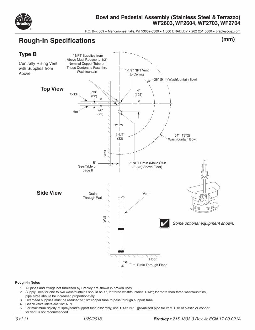
Type B
Centrally Rising Vent with Supplies from Above
1" NPT Supplies from Above Must Reduce to 1/2" Nominal Copper Tube on
These Centers to Pass thru Washfountain
36" (914) Washfountain Bowl
1-1/2" NPT Vent to Ceiling
Cold
Hot
2" NPT Drain (Make Stub 3" (76) Above Floor)
54" (1372) Washfountain Bowl
See Table on page 8
7/8" (22)
B*
4" (102)
Wal
lW
all
Drain Through Wall
Top View
Side View
Drain Through Floor
Floor
Some optional equipment shown.
Rough-In Notes
1. All pipes and fittings not furnished by Bradley are shown in broken lines.2. Supply lines for one to two washfountains should be 1", for three washfountains 1-1/2"; for more than three washfountains,
pipe sizes should be increased proportionately.3. Overhead supplies must be reduced to 1/2" copper tube to pass through support tube.4. Check valve inlets are 1/2" NPT.5. For maximum rigidity of sprayhead/support tube assembly, use 1-1/2" NPT galvanized pipe for vent. Use of plastic or copper
for vent is not recommended.
7/8" (22)
1-1/4" (32)
Vent
7 of 11 1/29/2018 Bradley • 215-1833-3 Rev. A: ECN 17-00-021A
Bowl and Pedestal Assembly (Stainless Steel & Terrazzo) WF2603, WF2604, WF2703, WF2704
P.O. Box 309 • Menomonee Falls, WI 53052-0309 • 1 800 BRADLEY • 262 251 6000 • bradleycorp.com
(mm)Rough-In Specifications
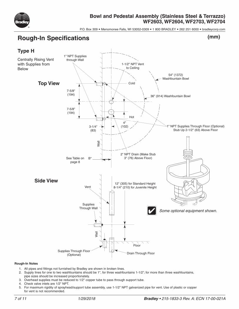
Type H
Centrally Rising Vent with Supplies from Below
1" NPT Supplies through Wall
36" (914) Washfountain Bowl
1-1/2" NPT Vent to Ceiling
Cold
Hot
2" NPT Drain (Make Stub 3" (76) Above Floor)
54" (1372) Washfountain Bowl
See Table on page 8
7-5/8" (194)
B*
4" (102)
Wal
lW
all
Supplies Through Wall
Top View
Side View
Drain Through Floor
Floor
Some optional equipment shown.
Rough-In Notes
1. All pipes and fittings not furnished by Bradley are shown in broken lines.2. Supply lines for one to two washfountains should be 1", for three washfountains 1-1/2"; for more than three washfountains,
pipe sizes should be increased proportionately.3. Overhead supplies must be reduced to 1/2" copper tube to pass through support tube.4. Check valve inlets are 1/2" NPT.5. For maximum rigidity of sprayhead/support tube assembly, use 1-1/2" NPT galvanized pipe for vent. Use of plastic or copper
for vent is not recommended.
3-1/4" (83)
Vent
Supplies Through Floor (Optional)
7-5/8" (194)
1" NPT Supplies Through Floor (Optional) Stub Up 2-1/2" (63) Above Floor
12" (305) for Standard Height 8-1/4" (210) for Juvenile Height
8 of 11 1/29/2018 Bradley • 215-1833-3 Rev. A: ECN 17-00-021A
Bowl and Pedestal Assembly (Stainless Steel & Terrazzo) WF2603, WF2604, WF2703, WF2704
P.O. Box 309 • Menomonee Falls, WI 53052-0309 • 1 800 BRADLEY • 262 251 6000 • bradleycorp.com
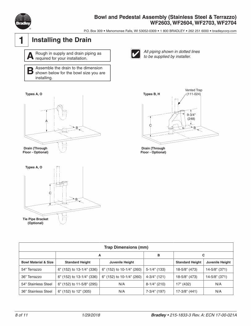
1 Installing the Drain
A Rough in supply and drain piping as required for your installation.
B Assemble the drain to the dimension shown below for the bowl size you are installing.
All piping shown in dotted lines to be supplied by installer.
Trap Dimensions (mm)
A B C
Bowl Material & Size Standard Height Juvenile Height Standard Height Juvenile Height
54" Terrazzo 6" (152) to 13-1/4" (336) 6" (152) to 10-1/4" (260) 5-1/4" (133) 18-5/8" (473) 14-5/8" (371)
36" Terrazzo 6" (152) to 13-1/4" (336) 6" (152) to 10-1/4" (260) 4-3/4" (121) 18-5/8" (473) 14-5/8" (371)
54" Stainless Steel 6" (152) to 11-5/8" (295) N/A 8-1/4" (210) 17" (432) N/A
36" Stainless Steel 6" (152) to 12" (305) N/A 7-3/4" (197) 17-3/8" (441) N/A
Types A, O
Drain (Through Floor - Optional)
A
B
Types B, H
Drain (Through Floor - Optional)
CB
9-3/4" (248)
Vented Trap (111-024)
Types A, O
Tie Pipe Bracket (Optional)
C
B
9 of 11 1/29/2018 Bradley • 215-1833-3 Rev. A: ECN 17-00-021A
Bowl and Pedestal Assembly (Stainless Steel & Terrazzo) WF2603, WF2604, WF2703, WF2704
P.O. Box 309 • Menomonee Falls, WI 53052-0309 • 1 800 BRADLEY • 262 251 6000 • bradleycorp.com
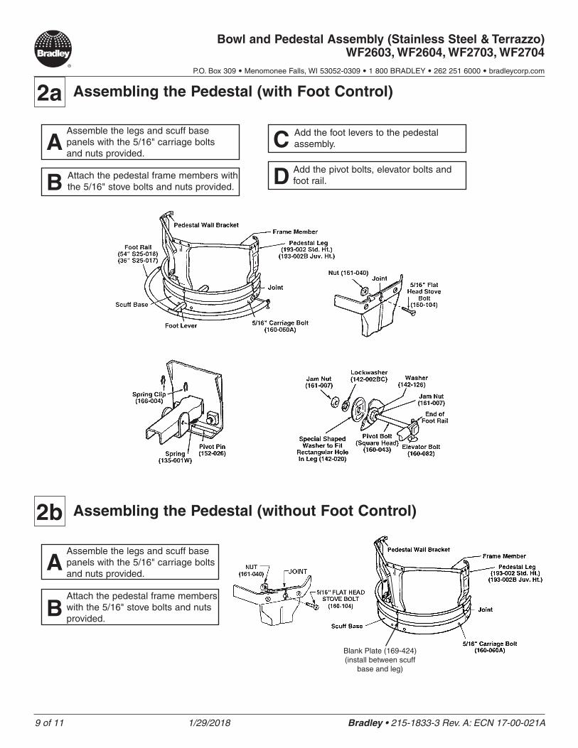
2a Assembling the Pedestal (with Foot Control)
AAssemble the legs and scuff base panels with the 5/16" carriage bolts and nuts provided.
B Attach the pedestal frame members with the 5/16" stove bolts and nuts provided.
C Add the foot levers to the pedestal assembly.
D Add the pivot bolts, elevator bolts and foot rail.
2b Assembling the Pedestal (without Foot Control)
AAssemble the legs and scuff base panels with the 5/16" carriage bolts and nuts provided.
BAttach the pedestal frame members with the 5/16" stove bolts and nuts provided.
Blank Plate (169-424) (install between scuff
base and leg)
10 of 11 1/29/2018 Bradley • 215-1833-3 Rev. A: ECN 17-00-021A
Bowl and Pedestal Assembly (Stainless Steel & Terrazzo) WF2603, WF2604, WF2703, WF2704
P.O. Box 309 • Menomonee Falls, WI 53052-0309 • 1 800 BRADLEY • 262 251 6000 • bradleycorp.com
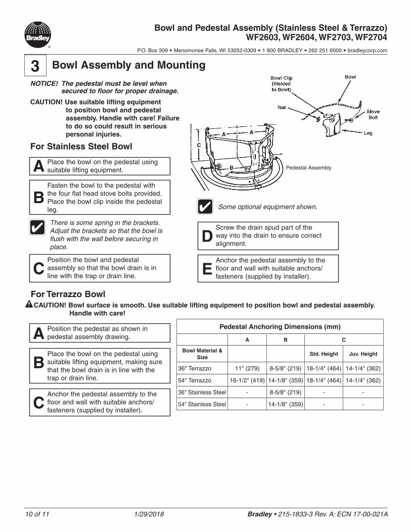
CAUTION! Use suitable lifting equipment to position bowl and pedestal assembly. Handle with care! Failure to do so could result in serious personal injuries.
A Place the bowl on the pedestal using suitable lifting equipment.
BFasten the bowl to the pedestal with the four flat head stove bolts provided. Place the bowl clip inside the pedestal leg.
NOTICE! The pedestal must be level when secured to floor for proper drainage.
Pedestal Anchoring Dimensions (mm)
A B C
Bowl Material & Size
Std. Height Juv. Height
36" Terrazzo 11" (279) 8-5/8" (219) 18-1/4" (464) 14-1/4" (362)
54" Terrazzo 16-1/2" (419) 14-1/8" (359) 18-1/4" (464) 14-1/4" (362)
36" Stainless Steel - 8-5/8" (219) - -
54" Stainless Steel - 14-1/8" (359) - -
3 Bowl Assembly and Mounting
There is some spring in the brackets. Adjust the brackets so that the bowl is flush with the wall before securing in place.
CPosition the bowl and pedestal assembly so that the bowl drain is in line with the trap or drain line.
DScrew the drain spud part of the way into the drain to ensure correct alignment.
EAnchor the pedestal assembly to the floor and wall with suitable anchors/fasteners (supplied by installer).
Pedestal Assembly
CAUTION! Bowl surface is smooth. Use suitable lifting equipment to position bowl and pedestal assembly. Handle with care!
A Position the pedestal as shown in pedestal assembly drawing.
BPlace the bowl on the pedestal using suitable lifting equipment, making sure that the bowl drain is in line with the trap or drain line.
CAnchor the pedestal assembly to the floor and wall with suitable anchors/fasteners (supplied by installer).
For Stainless Steel Bowl
For Terrazzo Bowl
Some optional equipment shown.
11 of 11 1/29/2018 Bradley • 215-1833-3 Rev. A: ECN 17-00-021A
Bowl and Pedestal Assembly (Stainless Steel & Terrazzo) WF2603, WF2604, WF2703, WF2704
P.O. Box 309 • Menomonee Falls, WI 53052-0309 • 1 800 BRADLEY • 262 251 6000 • bradleycorp.com
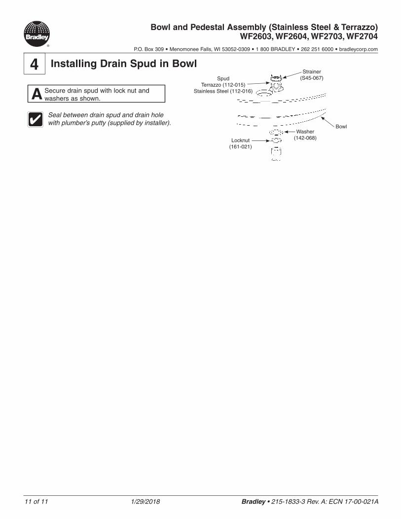
4 Installing Drain Spud in Bowl
A Secure drain spud with lock nut and washers as shown.
Seal between drain spud and drain hole with plumber’s putty (supplied by installer).
Strainer (S45-067)Spud
Terrazzo (112-015)Stainless Steel (112-016)
Washer (142-068)
Bowl
Locknut (161-021)
1 of 3 12/19/2017 Bradley • 215-1834-21 Rev. A: ECN 17-00-006B
Sprayheads WF2500, WF2600, WF2700, WF2800, WF3200, TDB3100 Series
P.O. Box 309 • Menomonee Falls, WI 53052-0309 • 1 800 BRADLEY • 262 251 6000 • bradleycorp.com
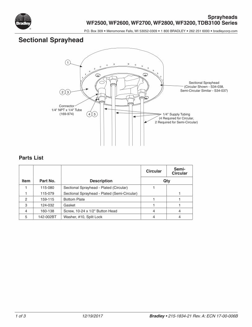
Sectional Sprayhead
1
32
54
Sectional Sprayhead (Circular Shown - S34-038,
Semi-Circular Similar - S34-037)
Connector 1/4" NPT x 1/4" Tube
(169-974) 1/4" Supply Tubing (4 Required for Circular,
2 Required for Semi-Circular)
Parts List
Item Part No. Description
Circular Semi-Circular
Qty
1 115-080 Sectional Sprayhead - Plated (Circular) 1
1 115-079 Sectional Sprayhead - Plated (Semi-Circular) 1
2 159-115 Bottom Plate 1 1
3 124-032 Gasket 1 1
4 160-138 Screw, 10-24 x 1/2" Button Head 4 4
5 142-002BT Washer, #10, Split Lock 4 4
2 of 3 12/19/2017 Bradley • 215-1834-21 Rev. A: ECN 17-00-006B
Sprayheads WF2500, WF2600, WF2700, WF2800, WF3200, TDB3100 Series
P.O. Box 309 • Menomonee Falls, WI 53052-0309 • 1 800 BRADLEY • 262 251 6000 • bradleycorp.com
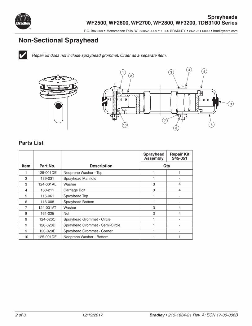
Non-Sectional Sprayhead
Repair kit does not include sprayhead grommet. Order as a separate item.
12
34 5
9
68
710
Parts List
Item Part No. Description
Sprayhead Assembly
Repair Kit S45-051
Qty
1 125-001DE Neoprene Washer - Top 1 1
2 139-031 Sprayhead Manifold 1 -
3 124-001AL Washer 3 4
4 160-211 Carriage Bolt 3 4
5 115-061 Sprayhead Top 1 -
6 116-008 Sprayhead Bottom 1 -
7 124-001AT Washer 3 4
8 161-025 Nut 3 4
9 124-020C Sprayhead Grommet - Circle 1 -
9 120-020D Sprayhead Grommet - Semi-Circle 1 -
9 120-020E Sprayhead Grommet - Corner 1 -
10 125-001DF Neoprene Washer - Bottom 1 1
3 of 3 12/19/2017 Bradley • 215-1834-21 Rev. A: ECN 17-00-006B
Sprayheads WF2500, WF2600, WF2700, WF2800, WF3200, TDB3100 Series
P.O. Box 309 • Menomonee Falls, WI 53052-0309 • 1 800 BRADLEY • 262 251 6000 • bradleycorp.com
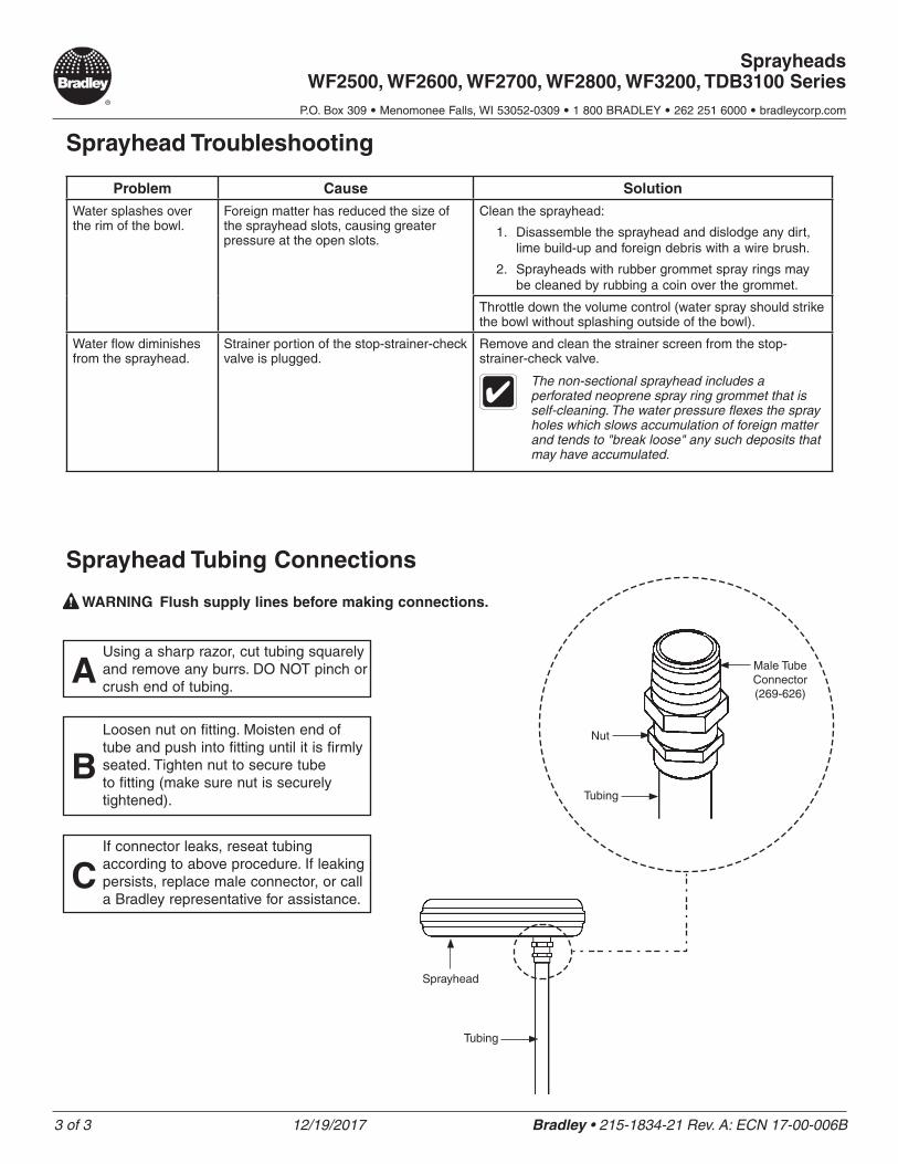
Sprayhead Troubleshooting
Problem Cause Solution
Water splashes over the rim of the bowl.
Foreign matter has reduced the size of the sprayhead slots, causing greater pressure at the open slots.
Clean the sprayhead:
1. Disassemble the sprayhead and dislodge any dirt, lime build-up and foreign debris with a wire brush.
2. Sprayheads with rubber grommet spray rings may be cleaned by rubbing a coin over the grommet.
Throttle down the volume control (water spray should strike the bowl without splashing outside of the bowl).
Water flow diminishes from the sprayhead.
Strainer portion of the stop-strainer-check valve is plugged.
Remove and clean the strainer screen from the stop-strainer-check valve.
The non-sectional sprayhead includes a perforated neoprene spray ring grommet that is self-cleaning. The water pressure flexes the spray holes which slows accumulation of foreign matter and tends to "break loose" any such deposits that may have accumulated.
Sprayhead Tubing Connections
WARNING Flush supply lines before making connections.
AUsing a sharp razor, cut tubing squarely and remove any burrs. DO NOT pinch or crush end of tubing.
BLoosen nut on fitting. Moisten end of tube and push into fitting until it is firmly seated. Tighten nut to secure tube to fitting (make sure nut is securely tightened).
CIf connector leaks, reseat tubing according to above procedure. If leaking persists, replace male connector, or call a Bradley representative for assistance.
Tubing
Sprayhead
Tubing
Nut
Male Tube Connector (269-626)
1 of 11 2/13/2018 Bradley • 215-1834-28 Rev. A: ECN 17-00-020
Air Metering Activation Modules - Non-Sectional Semi-Circular Washfountains WF2603, WF2604, WF2703, WF2704
P.O. Box 309 • Menomonee Falls, WI 53052-0309 • 1 800 BRADLEY • 262 251 6000 • bradleycorp.com
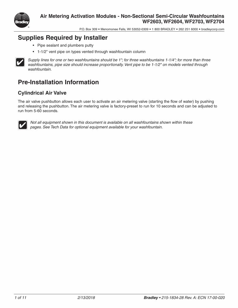
Supplies Required by Installer• Pipe sealant and plumbers putty
• 1-1/2" vent pipe on types vented through washfountain column
Pre-Installation Information
Cylindrical Air Valve
The air valve pushbutton allows each user to activate an air metering valve (starting the flow of water) by pushing and releasing the pushbutton. The air metering valve is factory-preset to run for 10 seconds and can be adjusted to run from 5-60 seconds.
Not all equipment shown in this document is available on all washfountains shown within these pages. See Tech Data for optional equipment available for your washfountain.
Supply lines for one or two washfountains should be 1"; for three washfountains 1-1/4"; for more than three washfountains, pipe size should increase proportionally. Vent pipe to be 1-1/2" on models vented through washfountain.
2 of 11 2/13/2018 Bradley • 215-1834-28 Rev. A: ECN 17-00-020
Air Metering Activation Modules - Non-Sectional Semi-Circular Washfountains WF2603, WF2604, WF2703, WF2704
P.O. Box 309 • Menomonee Falls, WI 53052-0309 • 1 800 BRADLEY • 262 251 6000 • bradleycorp.com
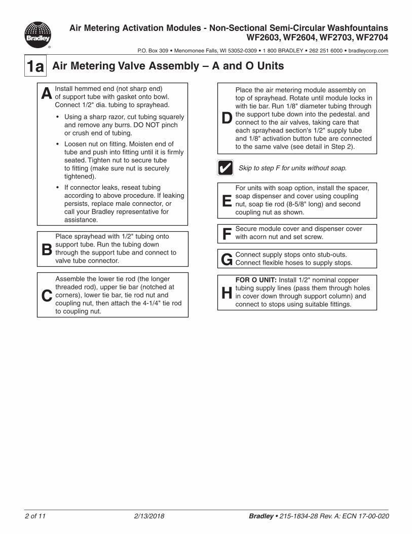
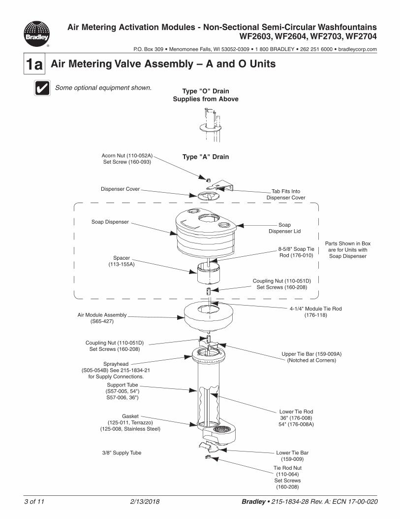
1a Air Metering Valve Assembly – A and O Units
BPlace sprayhead with 1/2" tubing onto support tube. Run the tubing down through the support tube and connect to valve tube connector.
CAssemble the lower tie rod (the longer threaded rod), upper tie bar (notched at corners), lower tie bar, tie rod nut and coupling nut, then attach the 4-1/4" tie rod to coupling nut.
D
Place the air metering module assembly on top of sprayhead. Rotate until module locks in with tie bar. Run 1/8" diameter tubing through the support tube down into the pedestal. and connect to the air valves, taking care that each sprayhead section's 1/2" supply tube and 1/8" activation button tube are connected to the same valve (see detail in Step 2).
Skip to step F for units without soap.
EFor units with soap option, install the spacer, soap dispenser and cover using coupling nut, soap tie rod (8-5/8" long) and second coupling nut as shown.
F Secure module cover and dispenser cover with acorn nut and set screw.
G Connect supply stops onto stub-outs. Connect flexible hoses to supply stops.
A Install hemmed end (not sharp end) of support tube with gasket onto bowl. Connect 1/2" dia. tubing to sprayhead.
• Using a sharp razor, cut tubing squarely and remove any burrs. DO NOT pinch or crush end of tubing.
• Loosen nut on fitting. Moisten end of tube and push into fitting until it is firmly seated. Tighten nut to secure tube to fitting (make sure nut is securely tightened).
• If connector leaks, reseat tubing according to above procedure. If leaking persists, replace male connector, or call your Bradley representative for assistance.
HFOR O UNIT: Install 1/2" nominal copper tubing supply lines (pass them through holes in cover down through support column) and connect to stops using suitable fittings.
3 of 11 2/13/2018 Bradley • 215-1834-28 Rev. A: ECN 17-00-020
Air Metering Activation Modules - Non-Sectional Semi-Circular Washfountains WF2603, WF2604, WF2703, WF2704
P.O. Box 309 • Menomonee Falls, WI 53052-0309 • 1 800 BRADLEY • 262 251 6000 • bradleycorp.com
1a Air Metering Valve Assembly – A and O Units
Type "O" Drain Supplies from Above
Type "A" DrainAcorn Nut (110-052A) Set Screw (160-093)
Dispenser Cover
Soap DispenserSoap
Dispenser Lid
4-1/4" Module Tie Rod (176-118)
8-5/8" Soap Tie Rod (176-010)Spacer
(113-155A)
Coupling Nut (110-051D) Set Screws (160-208)
Sprayhead (S05-054B) See 215-1834-21
for Supply Connections.
Lower Tie Rod 36" (176-008)
54" (176-008A)
Support Tube (S57-005, 54") S57-006, 36")
3/8" Supply Tube
Gasket (125-011, Terrazzo)
(125-008, Stainless Steel)
Lower Tie Bar (159-009)
Tie Rod Nut (110-064)
Set Screws (160-208)
Some optional equipment shown.
Parts Shown in Box are for Units with Soap Dispenser
Tab Fits Into Dispenser Cover
Air Module Assembly (S65-427)
Coupling Nut (110-051D) Set Screws (160-208)
Upper Tie Bar (159-009A) (Notched at Corners)
4 of 11 2/13/2018 Bradley • 215-1834-28 Rev. A: ECN 17-00-020
Air Metering Activation Modules - Non-Sectional Semi-Circular Washfountains WF2603, WF2604, WF2703, WF2704
P.O. Box 309 • Menomonee Falls, WI 53052-0309 • 1 800 BRADLEY • 262 251 6000 • bradleycorp.com
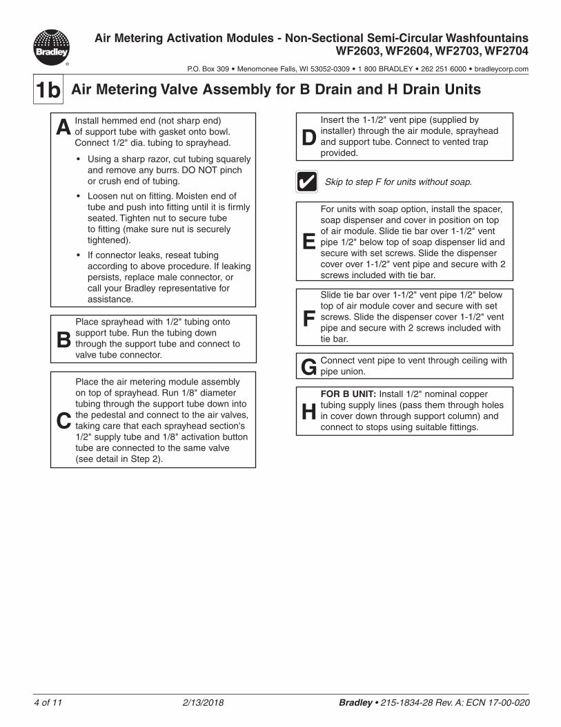
1b Air Metering Valve Assembly for B Drain and H Drain Units
BPlace sprayhead with 1/2" tubing onto support tube. Run the tubing down through the support tube and connect to valve tube connector.
C
Place the air metering module assembly on top of sprayhead. Run 1/8" diameter tubing through the support tube down into the pedestal and connect to the air valves, taking care that each sprayhead section's 1/2" supply tube and 1/8" activation button tube are connected to the same valve (see detail in Step 2).
Skip to step F for units without soap.
E
For units with soap option, install the spacer, soap dispenser and cover in position on top of air module. Slide tie bar over 1-1/2" vent pipe 1/2" below top of soap dispenser lid and secure with set screws. Slide the dispenser cover over 1-1/2" vent pipe and secure with 2 screws included with tie bar.
FSlide tie bar over 1-1/2" vent pipe 1/2" below top of air module cover and secure with set screws. Slide the dispenser cover 1-1/2" vent pipe and secure with 2 screws included with tie bar.
G Connect vent pipe to vent through ceiling with pipe union.
A Install hemmed end (not sharp end) of support tube with gasket onto bowl. Connect 1/2" dia. tubing to sprayhead.
• Using a sharp razor, cut tubing squarely and remove any burrs. DO NOT pinch or crush end of tubing.
• Loosen nut on fitting. Moisten end of tube and push into fitting until it is firmly seated. Tighten nut to secure tube to fitting (make sure nut is securely tightened).
• If connector leaks, reseat tubing according to above procedure. If leaking persists, replace male connector, or call your Bradley representative for assistance.
DInsert the 1-1/2" vent pipe (supplied by installer) through the air module, sprayhead and support tube. Connect to vented trap provided.
HFOR B UNIT: Install 1/2" nominal copper tubing supply lines (pass them through holes in cover down through support column) and connect to stops using suitable fittings.
5 of 11 2/13/2018 Bradley • 215-1834-28 Rev. A: ECN 17-00-020
Air Metering Activation Modules - Non-Sectional Semi-Circular Washfountains WF2603, WF2604, WF2703, WF2704
P.O. Box 309 • Menomonee Falls, WI 53052-0309 • 1 800 BRADLEY • 262 251 6000 • bradleycorp.com
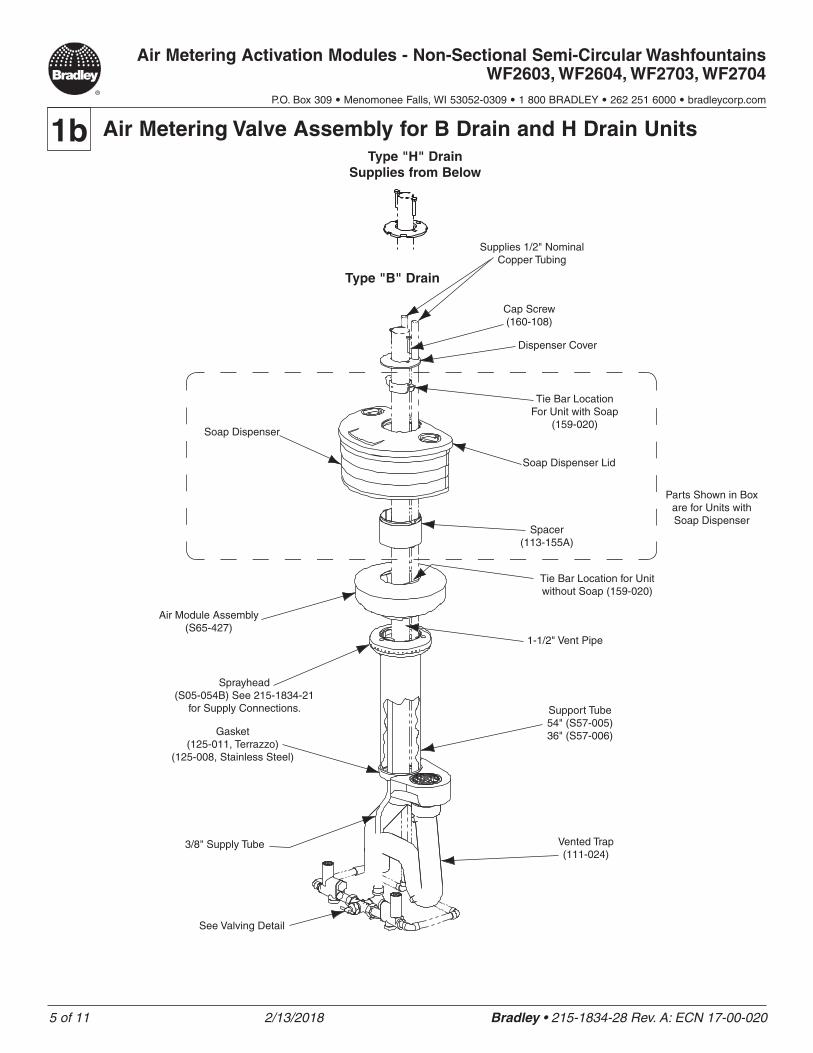
1b Air Metering Valve Assembly for B Drain and H Drain UnitsType "H" Drain
Supplies from Below
Type "B" Drain
Cap Screw (160-108)
Dispenser Cover
Supplies 1/2" Nominal Copper Tubing
Tie Bar Location For Unit with Soap
(159-020)Soap Dispenser
Soap Dispenser Lid
Spacer (113-155A)
Tie Bar Location for Unit without Soap (159-020)
Support Tube 54" (S57-005) 36" (S57-006)Gasket
(125-011, Terrazzo) (125-008, Stainless Steel)
Vented Trap (111-024)
See Valving Detail
1-1/2" Vent Pipe
Parts Shown in Box are for Units with Soap Dispenser
Air Module Assembly (S65-427)
Sprayhead (S05-054B) See 215-1834-21
for Supply Connections.
3/8" Supply Tube
6 of 11 2/13/2018 Bradley • 215-1834-28 Rev. A: ECN 17-00-020
Air Metering Activation Modules - Non-Sectional Semi-Circular Washfountains WF2603, WF2604, WF2703, WF2704
P.O. Box 309 • Menomonee Falls, WI 53052-0309 • 1 800 BRADLEY • 262 251 6000 • bradleycorp.com
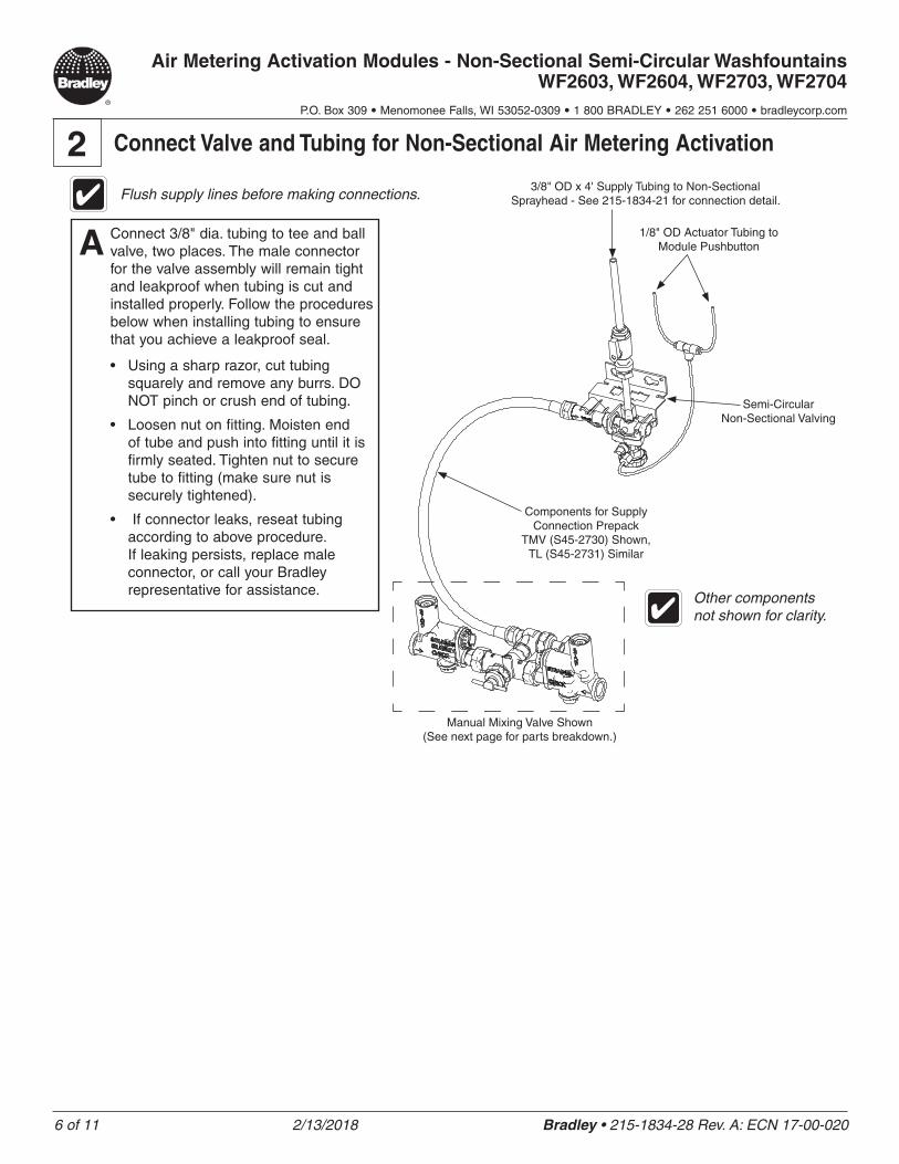
2 Connect Valve and Tubing for Non-Sectional Air Metering Activation
A Connect 3/8" dia. tubing to tee and ball valve, two places. The male connector for the valve assembly will remain tight and leakproof when tubing is cut and installed properly. Follow the procedures below when installing tubing to ensure that you achieve a leakproof seal.
• Using a sharp razor, cut tubing squarely and remove any burrs. DO NOT pinch or crush end of tubing.
• Loosen nut on fitting. Moisten end of tube and push into fitting until it is firmly seated. Tighten nut to secure tube to fitting (make sure nut is securely tightened).
• If connector leaks, reseat tubing according to above procedure. If leaking persists, replace male connector, or call your Bradley representative for assistance.
1/8" OD Actuator Tubing to Module Pushbutton
3/8" OD x 4' Supply Tubing to Non-Sectional Sprayhead - See 215-1834-21 for connection detail.
Components for Supply Connection Prepack
TMV (S45-2730) Shown, TL (S45-2731) Similar
Other components not shown for clarity.
Flush supply lines before making connections.
Semi-Circular Non-Sectional Valving
Manual Mixing Valve Shown (See next page for parts breakdown.)
7 of 11 2/13/2018 Bradley • 215-1834-28 Rev. A: ECN 17-00-020
Air Metering Activation Modules - Non-Sectional Semi-Circular Washfountains WF2603, WF2604, WF2703, WF2704
P.O. Box 309 • Menomonee Falls, WI 53052-0309 • 1 800 BRADLEY • 262 251 6000 • bradleycorp.com
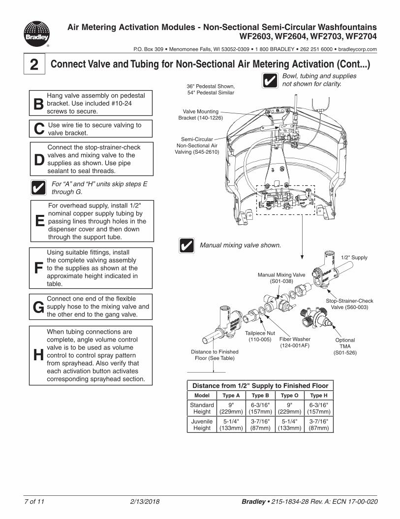
2 Connect Valve and Tubing for Non-Sectional Air Metering Activation (Cont...)
Semi-Circular Non-Sectional Air
Valving (S45-2610)
36" Pedestal Shown, 54" Pedestal Similar
Bowl, tubing and supplies not shown for clarity.
C Use wire tie to secure valving to valve bracket.
BHang valve assembly on pedestal bracket. Use included #10-24 screws to secure.
Manual mixing valve shown.
Distance to Finished Floor (See Table)
Tailpiece Nut (110-005) Fiber Washer
(124-001AF)Optional
TMA (S01-526)
Stop-Strainer-Check Valve (S60-003)
1/2" Supply
Manual Mixing Valve (S01-038)
Distance from 1/2" Supply to Finished FloorModel Type A Type B Type O Type H
Standard Height
9" (229mm)
6-3/16" (157mm)
9" (229mm)
6-3/16" (157mm)
Juvenile Height
5-1/4" (133mm)
3-7/16" (87mm)
5-1/4" (133mm)
3-7/16" (87mm)
DConnect the stop-strainer-check valves and mixing valve to the supplies as shown. Use pipe sealant to seal threads.
GConnect one end of the flexible supply hose to the mixing valve and the other end to the gang valve.
FUsing suitable fittings, install the complete valving assembly to the supplies as shown at the approximate height indicated in table.
For “A” and “H” units skip steps E through G.
EFor overhead supply, install 1/2" nominal copper supply tubing by passing lines through holes in the dispenser cover and then down through the support tube.
H
When tubing connections are complete, angle volume control valve is to be used as volume control to control spray pattern from sprayhead. Also verify that each activation button activates corresponding sprayhead section.
Valve Mounting Bracket (140-1226)
8 of 11 2/13/2018 Bradley • 215-1834-28 Rev. A: ECN 17-00-020
Air Metering Activation Modules - Non-Sectional Semi-Circular Washfountains WF2603, WF2604, WF2703, WF2704
P.O. Box 309 • Menomonee Falls, WI 53052-0309 • 1 800 BRADLEY • 262 251 6000 • bradleycorp.com
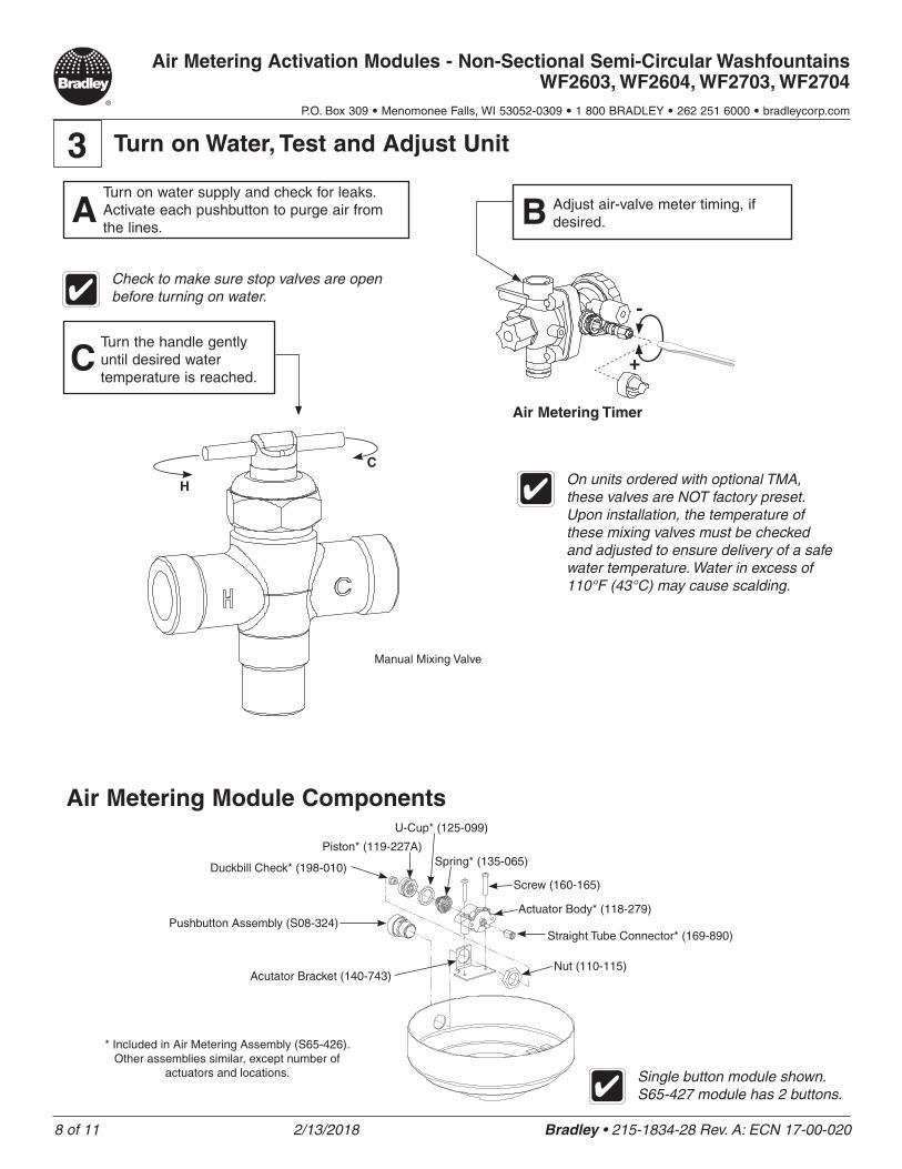
Air Metering Module Components
* Included in Air Metering Assembly (S65-426). Other assemblies similar, except number of
actuators and locations.
Duckbill Check* (198-010)
Piston* (119-227A)
U-Cup* (125-099)
Spring* (135-065)
Screw (160-165)
Actuator Body* (118-279)
Straight Tube Connector* (169-890)
Nut (110-115)Acutator Bracket (140-743)
Pushbutton Assembly (S08-324)
Single button module shown. S65-427 module has 2 buttons.
Check to make sure stop valves are open before turning on water.
CTurn the handle gently until desired water temperature is reached.
On units ordered with optional TMA, these valves are NOT factory preset. Upon installation, the temperature of these mixing valves must be checked and adjusted to ensure delivery of a safe water temperature. Water in excess of 110°F (43°C) may cause scalding.
3 Turn on Water, Test and Adjust Unit
H
C
Manual Mixing Valve
Air Metering Timer
+
-
ATurn on water supply and check for leaks. Activate each pushbutton to purge air from the lines.
B Adjust air-valve meter timing, if desired.
9 of 11 2/13/2018 Bradley • 215-1834-28 Rev. A: ECN 17-00-020
Air Metering Activation Modules - Non-Sectional Semi-Circular Washfountains WF2603, WF2604, WF2703, WF2704
P.O. Box 309 • Menomonee Falls, WI 53052-0309 • 1 800 BRADLEY • 262 251 6000 • bradleycorp.com
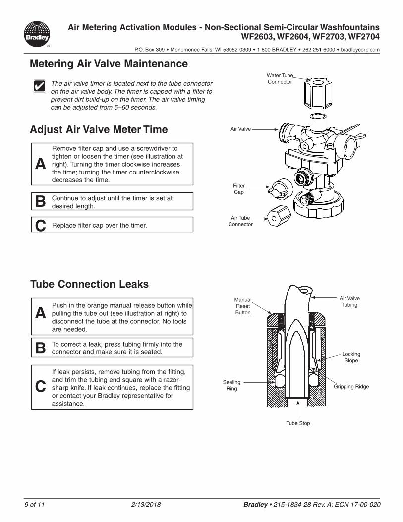
Metering Air Valve Maintenance
The air valve timer is located next to the tube connector on the air valve body. The timer is capped with a filter to prevent dirt build-up on the timer. The air valve timing can be adjusted from 5–60 seconds.
Adjust Air Valve Meter Time
Tube Connection Leaks
ARemove filter cap and use a screwdriver to tighten or loosen the timer (see illustration at right). Turning the timer clockwise increases the time; turning the timer counterclockwise decreases the time.
B Continue to adjust until the timer is set at desired length.
C Replace filter cap over the timer.
Water Tube Connector
Air Valve
Filter Cap
Air Tube Connector
APush in the orange manual release button while pulling the tube out (see illustration at right) to disconnect the tube at the connector. No tools are needed.
B To correct a leak, press tubing firmly into the connector and make sure it is seated.
CIf leak persists, remove tubing from the fitting, and trim the tubing end square with a razor-sharp knife. If leak continues, replace the fitting or contact your Bradley representative for assistance.
Manual Reset Button
Air Valve Tubing
Sealing Ring
Tube Stop
Gripping Ridge
Locking Slope
10 of 11 2/13/2018 Bradley • 215-1834-28 Rev. A: ECN 17-00-020
Air Metering Activation Modules - Non-Sectional Semi-Circular Washfountains WF2603, WF2604, WF2703, WF2704
P.O. Box 309 • Menomonee Falls, WI 53052-0309 • 1 800 BRADLEY • 262 251 6000 • bradleycorp.com
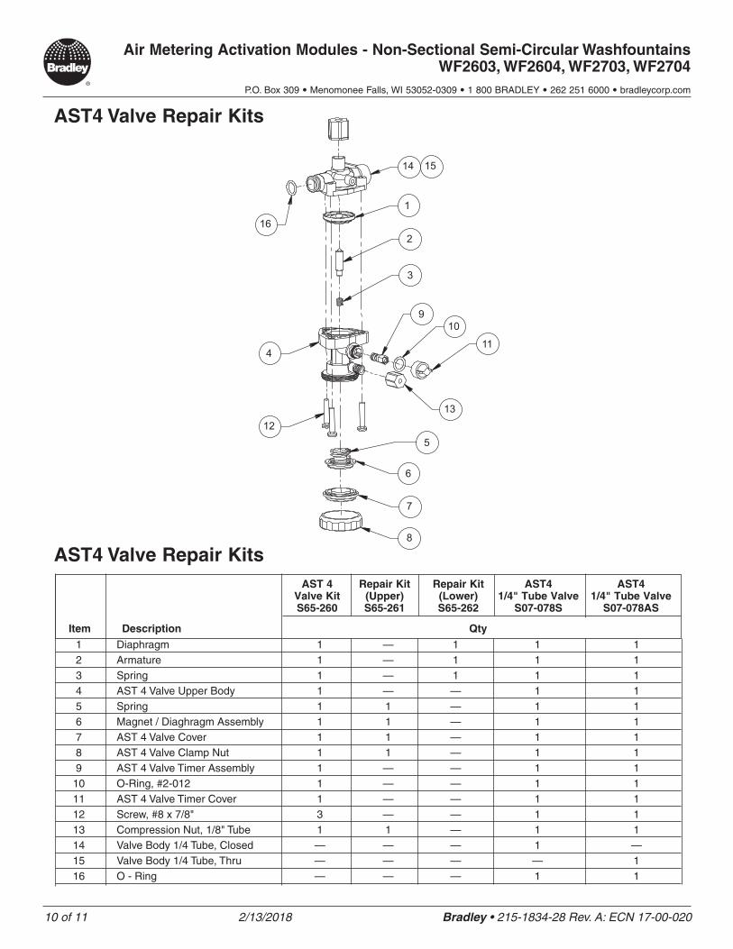
1 Diaphragm 1 — 1 1 1 2 Armature 1 — 1 1 1 3 Spring 1 — 1 1 1 4 AST 4 Valve Upper Body 1 — — 1 1 5 Spring 1 1 — 1 1 6 Magnet / Diaghragm Assembly 1 1 — 1 1 7 AST 4 Valve Cover 1 1 — 1 1 8 AST 4 Valve Clamp Nut 1 1 — 1 1 9 AST 4 Valve Timer Assembly 1 — — 1 1 10 O-Ring, #2-012 1 — — 1 1 11 AST 4 Valve Timer Cover 1 — — 1 1 12 Screw, #8 x 7/8" 3 — — 1 1 13 Compression Nut, 1/8" Tube 1 1 — 1 1 14 Valve Body 1/4 Tube, Closed — — — 1 — 15 Valve Body 1/4 Tube, Thru — — — — 1 16 O - Ring — — — 1 1
8
7
6
5
1312
411
109
3
2
1
16
14 15
AST 4 Repair Kit Repair Kit AST4 AST4 Valve Kit (Upper) (Lower) 1/4" Tube Valve 1/4" Tube Valve S65-260 S65-261 S65-262 S07-078S S07-078AS
Item Description Qty
AST4 Valve Repair Kits
AST4 Valve Repair Kits
11 of 11 2/13/2018 Bradley • 215-1834-28 Rev. A: ECN 17-00-020
Air Metering Activation Modules - Non-Sectional Semi-Circular Washfountains WF2603, WF2604, WF2703, WF2704
P.O. Box 309 • Menomonee Falls, WI 53052-0309 • 1 800 BRADLEY • 262 251 6000 • bradleycorp.com
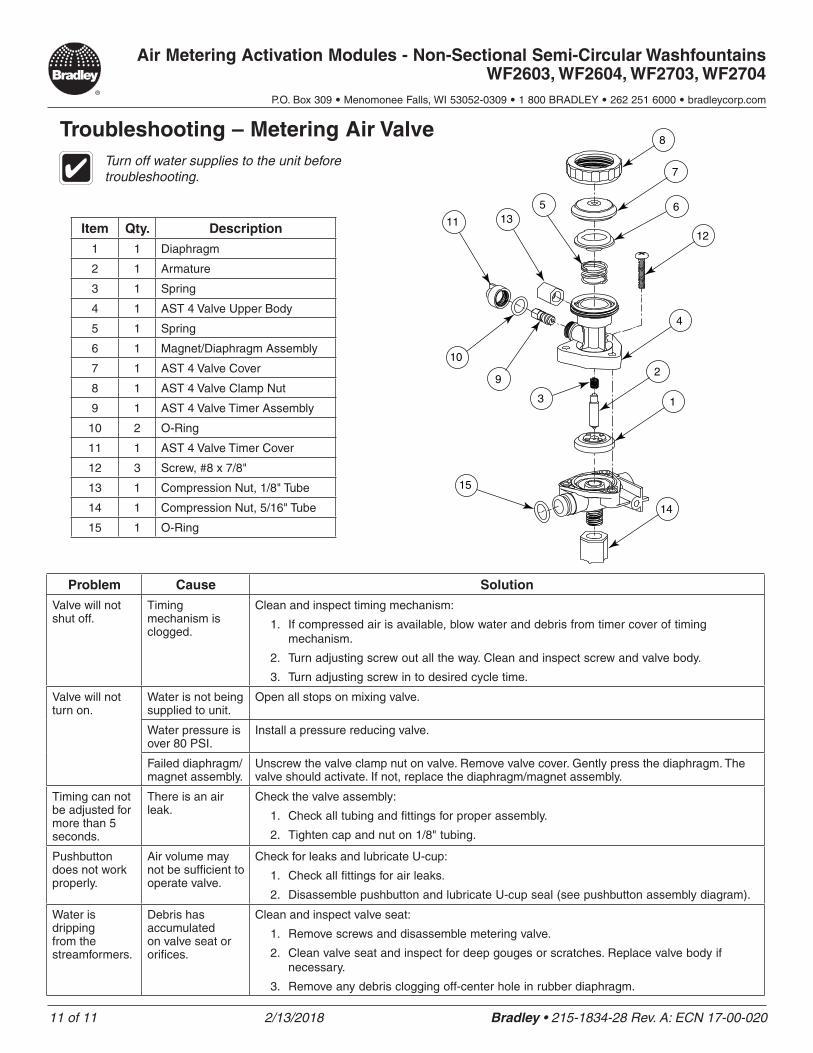
Turn off water supplies to the unit before troubleshooting.
Troubleshooting – Metering Air Valve
Problem Cause Solution
Valve will not shut off.
Timing mechanism is clogged.
Clean and inspect timing mechanism:
1. If compressed air is available, blow water and debris from timer cover of timing mechanism.
2. Turn adjusting screw out all the way. Clean and inspect screw and valve body.
3. Turn adjusting screw in to desired cycle time.
Valve will not turn on.
Water is not being supplied to unit.
Open all stops on mixing valve.
Water pressure is over 80 PSI.
Install a pressure reducing valve.
Failed diaphragm/magnet assembly.
Unscrew the valve clamp nut on valve. Remove valve cover. Gently press the diaphragm. The valve should activate. If not, replace the diaphragm/magnet assembly.
Timing can not be adjusted for more than 5 seconds.
There is an air leak.
Check the valve assembly:
1. Check all tubing and fittings for proper assembly.
2. Tighten cap and nut on 1/8" tubing.
Pushbutton does not work properly.
Air volume may not be sufficient to operate valve.
Check for leaks and lubricate U-cup:
1. Check all fittings for air leaks.
2. Disassemble pushbutton and lubricate U-cup seal (see pushbutton assembly diagram).
Water is dripping from the streamformers.
Debris has accumulated on valve seat or orifices.
Clean and inspect valve seat:
1. Remove screws and disassemble metering valve.
2. Clean valve seat and inspect for deep gouges or scratches. Replace valve body if necessary.
3. Remove any debris clogging off-center hole in rubber diaphragm.
1
2
14
12
10
11
15
135
4
3
9
7
8
6
Item Qty. Description
1 1 Diaphragm
2 1 Armature
3 1 Spring
4 1 AST 4 Valve Upper Body
5 1 Spring
6 1 Magnet/Diaphragm Assembly
7 1 AST 4 Valve Cover
8 1 AST 4 Valve Clamp Nut
9 1 AST 4 Valve Timer Assembly
10 2 O-Ring
11 1 AST 4 Valve Timer Cover
12 3 Screw, #8 x 7/8"
13 1 Compression Nut, 1/8" Tube
14 1 Compression Nut, 5/16" Tube
15 1 O-Ring