Embed Size (px)
Citation preview

115109
AkronFlow/Pressure
systemsGPm/PsI
style 9300
InstAllAtIonCAlIbrAtIonoPerAtIon
InstruCtIons
tAble oF Contents
Section DeScription page
i installation instructions 1
ii calibration instructions 3
iii operation instructions 5
iV troubleshooting guide 6
V replacement parts 7
list of Figures / tables
Figure 1 Flow Sensor
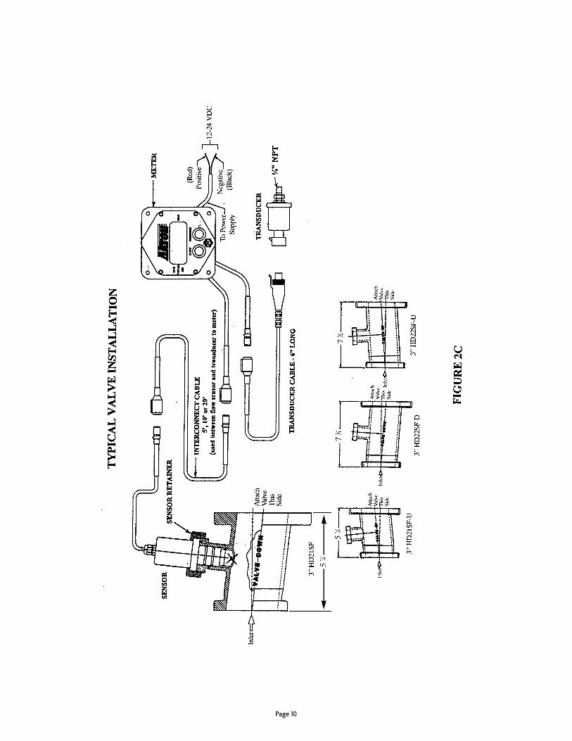
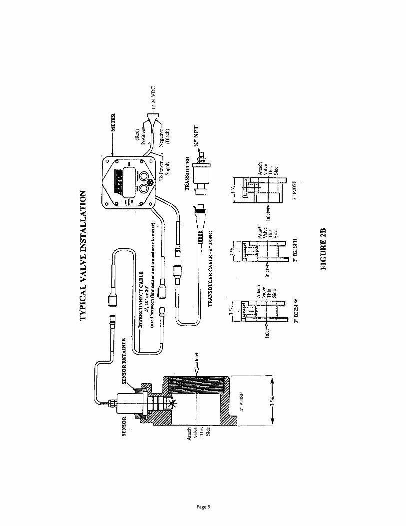
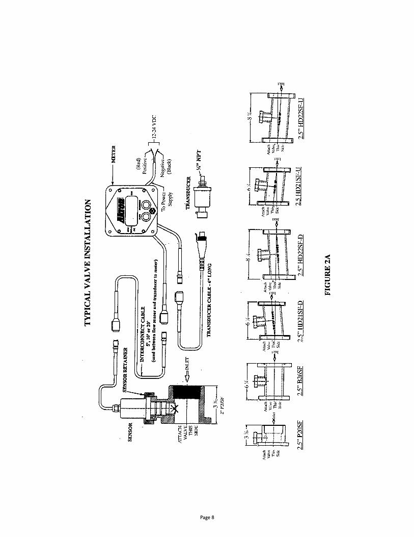
Figure 2 a,B,c, typical Valve installations
Figure 3 Saddle clamps
Figure 4 pressure transducer
Figure 5 Meter Functions
Figure 6 Meter installation guide
table 1 Flow chart
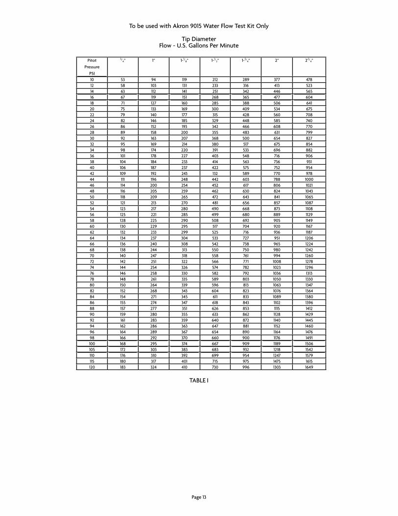
pitotpressure
pSi
3/4” 1” 1-1/
8” 1-1/2” 1-3/
4” 2” 2’1/4”
10 53 94 119 212 289 377 47812 58 103 131 233 316 413 52314 63 112 141 251 342 446 56516 67 119 151 268 365 477 60418 71 127 160 285 388 506 64120 75 133 169 300 409 534 67522 79 140 177 315 428 560 70824 82 146 185 329 448 585 74026 86 152 193 342 466 608 77028 89 158 200 355 483 631 79930 92 163 207 368 500 654 82732 95 169 214 380 517 675 85434 98 174 220 391 533 696 88236 101 178 227 403 548 716 90638 104 184 233 414 563 736 93140 106 187 237 422 575 752 95442 109 192 243 132 589 770 97844 111 196 248 442 603 788 100046 114 200 254 452 617 806 102148 116 205 259 462 630 824 104350 118 209 265 472 643 841 106552 121 213 270 481 656 857 108754 123 217 280 490 668 873 110856 125 221 285 499 680 889 112958 128 225 290 508 692 905 114960 130 229 295 517 704 920 116762 132 233 299 525 716 936 118764 134 237 304 533 727 951 120666 136 240 308 542 738 965 122468 138 244 313 550 750 980 124270 140 247 318 558 761 994 126072 142 251 322 566 771 1008 127874 144 254 326 574 782 1023 129676 146 258 330 582 792 1036 131378 148 261 335 589 803 1050 133080 150 264 339 596 813 1063 134782 152 268 343 604 823 1076 136484 154 271 345 611 833 1089 138086 155 274 347 618 843 1102 139688 157 277 351 626 853 1115 141290 159 280 355 633 862 1128 142992 161 283 359 640 872 1140 144594 162 286 363 647 881 1152 146096 164 289 367 654 890 1164 147698 166 292 370 660 900 1176 1491100 168 295 374 667 909 1189 1506105 172 303 383 683 932 1218 1542110 176 310 392 699 954 1247 1579115 180 317 401 715 975 1475 1615120 183 324 410 730 996 1303 1649
taBLe i
to be used with akron 9015 Water Flow test Kit only
tip DiameterFlow - U.S. gallons per Minute
page 13

Left Buttonpress and release to change Mode to gpM or totaL press and hold to change LeD intensity.
right Buttonpress and release to change Mode to pressure (pSi)
actUaL FLoW totaL gaLLonS FLoWeD DiScHarge preSSUre 500 gpM 100 X 100 = 10,000 118 pSi
PAnel Cutout DImensIonsA. mAIn oPenInG 3-15/16”b. mountInG—Four 7/32” Holes on A 4.950”b. bolt CIrCle
meter InstAllAtIon GuIDe
page 12
seCtIon IInstAllAtIon InstruCtIons
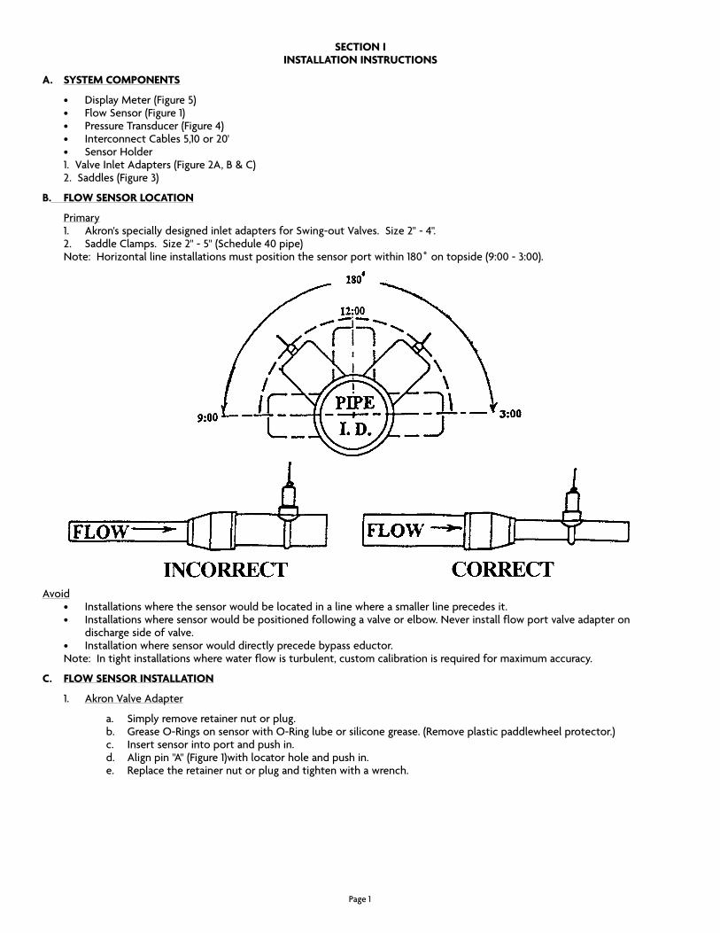
A. system ComPonents
• DisplayMeter(Figure5) • FlowSensor(Figure1) • PressureTransducer(Figure4) • InterconnectCables5,10or20' • SensorHolder 1. Valve inlet adapters (Figure 2a, B & c) 2. Saddles (Figure 3)
b. Flow sensor loCAtIon
primary 1. Akron'sspeciallydesignedinletadaptersforSwing-outValves.Size2"-4". 2. SaddleClamps.Size2"-5"(Schedule40pipe) Note:Horizontallineinstallationsmustpositionthesensorportwithin180˚ontopside(9:00-3:00).
avoid • Installationswherethesensorwouldbelocatedinalinewhereasmallerlineprecedesit. • Installationswheresensorwouldbepositionedfollowingavalveorelbow.Neverinstallflowportvalveadapteron
discharge side of valve. • Installationwheresensorwoulddirectlyprecedebypasseductor. note: in tight installations where water flow is turbulent, custom calibration is required for maximum accuracy.
C. Flow sensor InstAllAtIon
1. akron Valve adapter
a. Simply remove retainer nut or plug. b. grease o-rings on sensor with o-ring lube or silicone grease. (remove plastic paddlewheel protector.) c. insert sensor into port and push in. d. Alignpin"A"(Figure1)withlocatorholeandpushin. e. replace the retainer nut or plug and tighten with a wrench.
page 1

Sensor installation complete
2. Saddle clamp
a. Determine the location on the pipe. b. Drill a 1-1/4"holeinthepipewithaholesaw.Horizontalpipingontopsidefrom9:00-3:00. c. Deburr the edge of the hole and clean the area where the gasket seals. d. Centersaddlewithholeinpipe(Sensorlocatorhole"A"(Figure3)maybeoneithersideofpipehole.) e. insert strap into saddle and tighten nuts hand tight. f. Using a torque wrench tighten nuts alternately to 80 foot pounds. g. Follow steps a - e in c.1 to add sensor.Sensor installation complete
D. Pressure trAnsDuCer InstAllAtIon
the pressure transducer (Figure 4) has a 1/4” npt male thread.
1. apply pipe sealant to the thread and insert into provided tapped hole in valve discharge adapter on discharge side of valve.2. tighten with wrench to torque used for small pipe fittings.
pressure transducer installation is now complete
e. meter InstAllAtIon
CAutIon: always disconnect all wiring and cables from the meter before electric arc welding at any point on apparatus. Failure to do so will result in damage to meter.
1. Select mounting location(s) for meter(s). the meter is to be mounted from the outside of the panel and will need clearance behind of 3-15/16” width by 2-1/
2” depth. See Figure 6 for cutout and screw mounting dimensions.
wArnInG:Themeterisasealedunitandthebezelshouldnotbedisassembledfromthecase.
2. after the cutout and mounting holes are finished, mount the meter using the provided fasteners.
3. it is now time to connect the red power wire and, the Black ground wire, to the truck system.
CAutIon: exercise caution when working with the electrical system. Disconnect cable from battery positive terminal before connecting power to meter. See truck manual for additional information on electrical system.
CAutIon: Do not connect meter to flow sensor or transducer cables until power hook up is verified correct and display is working. the meter has reverse polarity protection, but the transducer and flow sensor do not, since they require shielding. they will be grounded to the piping. any mis-wiring could damage all components.
note: it is essential that the connectors used be water-tight to prevent water from wicking up wires and into the meter. always use sealed connectors or splices and the adhesive lined shrink tube provided, or other suitable connectors.
4. Using 16 or 18 aWg wire, connect the red positive wire to the 12 or 24 VDc power supply. connect the Black negative wire to a suitable ground.
SpeciFicationS:
sensor types
Flow Meter - paddlewheel pressure transducer - ratio Metric, 0.5 - 4.5 VDc, 1/4” npt, Male, 0-600 pSi.
meter
operating Voltage 12 or 24 VDc Minimum operations Voltage - 9.5 VDc Maximum operations Voltage - 32.0 VDc operating current - 150 ma Display type - LeD enclosure - neMa 4X OperatingTemperature-40˚F-140˚F
F. PsI/GPm Power-uP oPtIon
akron Flow/pressure Meters, equipped with the pSi or gpM selection feature, allows the user to select the display function to appear on power-up. to make this selection, use the following procedure.
page 2

Pressure trAnsDuCer & ConneCtor
FIGure 4
page 11
page 10
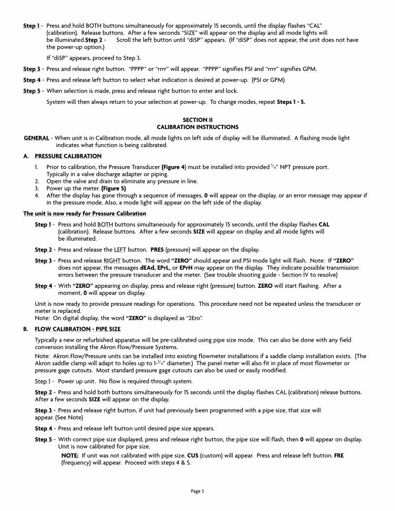
step 1 - press and hold BotH buttons simultaneously for approximately 15 seconds, until the display flashes “caL” (calibration). release buttons. after a few seconds “SiZe” will appear on the display and all mode lights will be illuminated.step 2 - Scroll the left button until “diSp” appears. (if “diSp” does not appear, the unit does not have the power-up option.)
if “diSp” appears, proceed to Step 3.
step 3 - press and release right button. “pppp” or “rrrr” will appear. “pppp” signifies pSi and “rrrr” signifies gpM.
step 4 - press and release left button to select what indication is desired at power-up. (pSi or gpM)
step 5 - When selection is made, press and release right button to enter and lock.
System will then always return to your selection at power-up. to change modes, repeat steps 1 - 5.
seCtIon IICAlIbrAtIon InstruCtIons
GenerAl - When unit is in calibration mode, all mode lights on left side of display will be illuminated. a flashing mode light indicates what function is being calibrated.
A. Pressure CAlIbrAtIon
1. prior to calibration, the pressure transducer (Figure 4) must be installed into provided 1/4” npt pressure port. typically in a valve discharge adapter or piping.
2. open the valve and drain to eliminate any pressure in line. 3. power up the meter. (Figure 5) 4. after the display has gone through a sequence of messages, 0 will appear on the display, or an error message may appear if
in the pressure mode. also, a mode light will appear on the left side of the display.
the unit is now ready for Pressure Calibration
step 1 - press and hold BotH buttons simultaneously for approximately 15 seconds, until the display flashes CAl (calibration). release buttons. after a few seconds sIZe will appear on display and all mode lights will be illuminated.
step 2 - press and release the LeFt button. Pres (pressure) will appear on the display.
step 3 - press and release rigHt button. the word “Zero” should appear and pSi mode light will flash. note: if “Zero” does not appear, the messages deAd, ePrl, or ePrH may appear on the display. they indicate possible transmission errors between the pressure transducer and the meter. (See trouble shooting guide - Section iV to resolve)
step 4 - With “Zero” appearing on display, press and release right (pressure) button. Zero will start flashing. after a moment, 0 will appear on display.
Unit is now ready to provide pressure readings for operations. this procedure need not be repeated unless the transducer or meter is replaced. note: on digital display, the word “Zero” is displayed as “2ero”.
b. Flow CAlIbrAtIon - PIPe sIZe
Typicallyaneworrefurbishedapparatuswillbepre-calibratedusingpipesizemode.Thiscanalsobedonewithanyfieldconversion installing the akron Flow/pressure Systems.
note: akron Flow/pressure units can be installed into existing flowmeter installations if a saddle clamp installation exists. (the akron saddle clamp will adapt to holes up to 1-3/4” diameter.) the panel meter will also fit in place of most flowmeter or pressure gage cutouts. Most standard pressure gage cutouts can also be used or easily modified.
Step 1 - power up unit. no flow is required through system.
step 2 - press and hold both buttons simultaneously for 15 seconds until the display flashes caL (calibration) release buttons. after a few seconds sIZe will appear on the display.
step 3- Pressandreleaserightbutton,ifunithadpreviouslybeenprogrammedwithapipesize,thatsizewill appear. (See note)
step 4-Pressandreleaseleftbuttonuntildesiredpipesizeappears.
step 5-Withcorrectpipesizedisplayed,pressandreleaserightbutton,thepipesizewillflash,then0 will appear on display. Unitisnowcalibratedforpipesize.
note:Ifunitwasnotcalibratedwithpipesize,Cus (custom) will appear. press and release left button. Fre (frequency) will appear. proceed with steps 4 & 5.
page 3
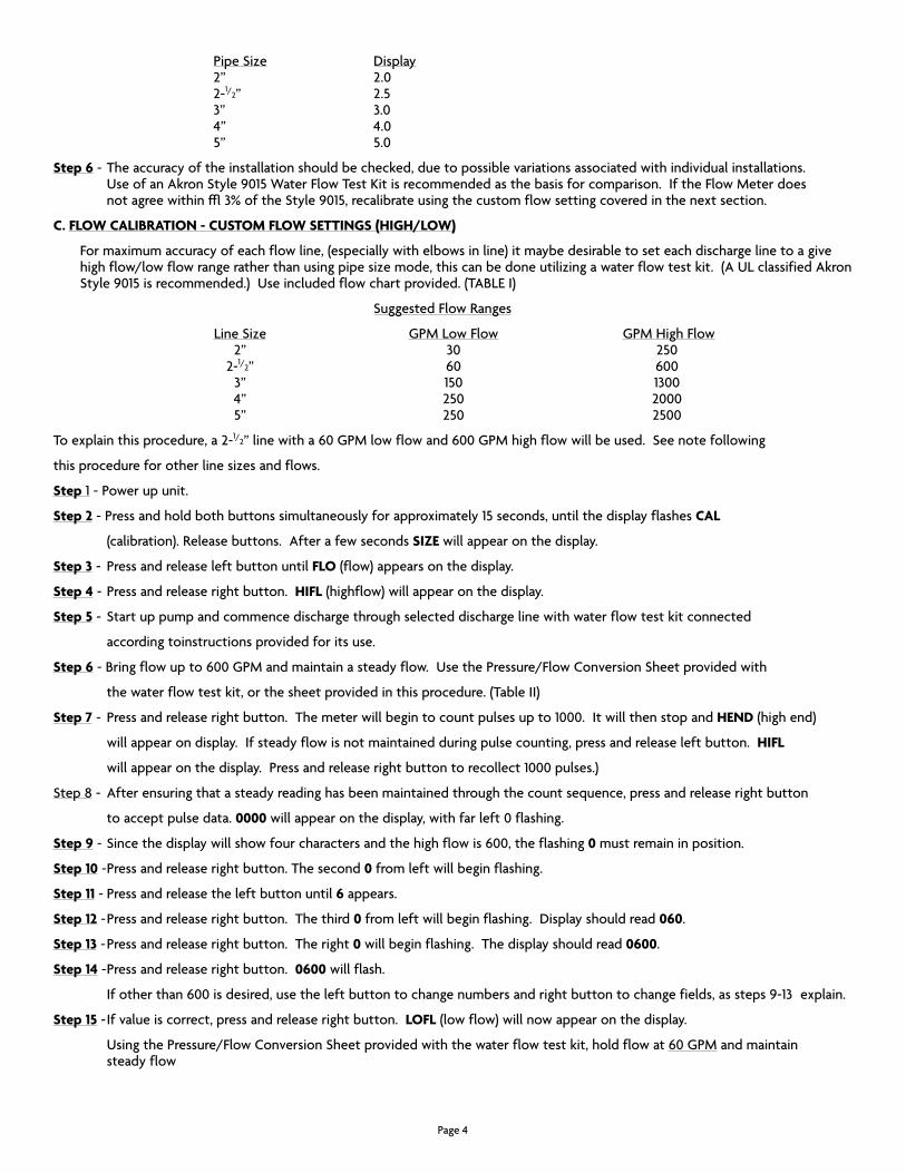
PipeSize Display 2” 2.0
2-1/2” 2.5 3” 3.0 4” 4.0 5” 5.0
step 6 - the accuracy of the installation should be checked, due to possible variations associated with individual installations. Use of an akron Style 9015 Water Flow test Kit is recommended as the basis for comparison. if the Flow Meter does not agree within ± 3% of the Style 9015, recalibrate using the custom flow setting covered in the next section.
C. Flow CAlIbrAtIon - Custom Flow settInGs (HIGH/low)
For maximum accuracy of each flow line, (especially with elbows in line) it maybe desirable to set each discharge line to a give highflow/lowflowrangeratherthanusingpipesizemode,thiscanbedoneutilizingawaterflowtestkit.(AULclassifiedAkronStyle 9015 is recommended.) Use included flow chart provided. (taBLe i)
Suggested Flow ranges
LineSize gpM Low Flow gpM High Flow 2” 30 250 2-1/2” 60 600 3” 150 1300 4” 250 2000 5” 250 2500
to explain this procedure, a 2-1/2” line with a 60 gpM low flow and 600 gpM high flow will be used. See note following
thisprocedureforotherlinesizesandflows.
step 1 - power up unit.
step 2 - press and hold both buttons simultaneously for approximately 15 seconds, until the display flashes CAl
(calibration). release buttons. after a few seconds sIZe will appear on the display.
step 3 - press and release left button until Flo (flow) appears on the display.
step 4 - press and release right button. HIFl (highflow) will appear on the display.
step 5 - Start up pump and commence discharge through selected discharge line with water flow test kit connected
according toinstructions provided for its use.
step 6 - Bring flow up to 600 gpM and maintain a steady flow. Use the pressure/Flow conversion Sheet provided with
the water flow test kit, or the sheet provided in this procedure. (table ii)
step 7 - press and release right button. the meter will begin to count pulses up to 1000. it will then stop and HenD (high end)
will appear on display. if steady flow is not maintained during pulse counting, press and release left button. HIFl
will appear on the display. press and release right button to recollect 1000 pulses.)
Step 8 - after ensuring that a steady reading has been maintained through the count sequence, press and release right button
to accept pulse data. 0000 will appear on the display, with far left 0 flashing.
step 9 - Since the display will show four characters and the high flow is 600, the flashing 0 must remain in position.
step 10 - press and release right button. the second 0 from left will begin flashing.
step 11 - press and release the left button until 6 appears.
step 12 - press and release right button. the third 0 from left will begin flashing. Display should read 060.
step 13 - press and release right button. the right 0 will begin flashing. the display should read 0600.
step 14 - press and release right button. 0600 will flash.
if other than 600 is desired, use the left button to change numbers and right button to change fields, as steps 9-13 explain.
step 15 - if value is correct, press and release right button. loFl (low flow) will now appear on the display.
Using the pressure/Flow conversion Sheet provided with the water flow test kit, hold flow at 60 gpM and maintain steady flow
page 4
page 9
page 8

step 16 - press and release right button. the meter will begin to count pulses to 1000. note: the Low flow pulse collection will take longer than high flow due to lower velocity.
step 17 - When 1000 pulses have been reached, the counting will stop. lenD (low end) will appear on display.
step 18 - press and release right button. 0000 will appear on the display. proceed as you did in steps 9-13, display should show 0060 after step 12 using 0060 instead of 0600.
step 19 - press and release right button. 0060 will flash.
step 20 -press and release right button. CAl (calibration) will flash momentarily, indicating that the meter is calibrated. Display will then show 0 with a mode indicator light.
step 21 - Verify Flow Meter calibration by comparing flows to the akron Style 9015 Water Flow test Kit.
Unit is now ready for use
note: the high flow settings should be 7 - 10 times the low flow settings.
seCtIon IIIoPerAtIon InstruCtIons
A. GenerAl
these instructions describe features and operational steps for general service after the system is set up and calibrated. (See installation and calibration sections i & ii if this has not been done.)
the meter consists of the display screen and two operation buttons located directly beneath the display. (See Figure 5)
When unit is powered, there are three red LeD mode lights on the left side of display. each of these lights align with particular functionmarkedonthebezelface.(SeeFigure5)Theywillonlybeilluminatedindividually,exceptduringpowerupsequenceand calibration.
the unit has four operation functions:
1. Flow GPm - actual gallons per minute flowing. (Will read in single gallon increments to 300. above 300, 10 gallon increments will appear.)
2. Flow totAl - total gallons flowed since unit was powered up. (Figure displayed must be multiplied X 100 to get total)
3. pressure PsI - actual pounds per square inch pressure.
4. LeD intenSitY - Brightness of display.
b. oPerAtIon (See Figure 5)
at the time of power up, all three mode lights will appear with four ZeroS. in sequence a number value will appear, followed by GAl, PsI, Cus or PIPe and finally 0. this will be complete in a few seconds.
the unit is now ready for operation
to reAD:
GPm - press and release left (flow) button to place mode light on GPm. actual gpM will appear on display.
totAl Flow - press and release left (flow) button to place mode light on totAl. the figures displayed must be multiplied by 100 to give gallons flowed.
PsI - press and release right (pressure) button to place mode light on PsI. actual pressure will appear on display.
leD IntensIty - to brighten or dim leD, press and hold left button until desired brightness is displayed.
refer to Section iV, troubleshooting guide if problems occur.
page 5
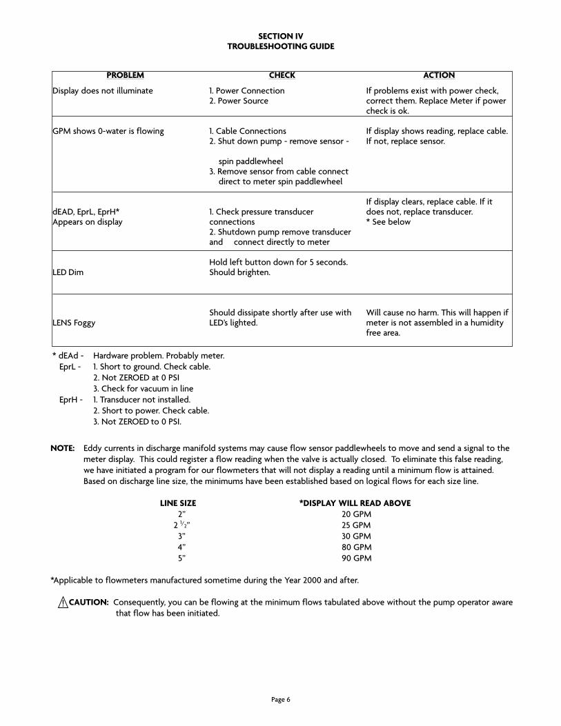
seCtIon IVtroublesHootInG GuIDe
Problem
Display does not illuminate
gpM shows 0-water is flowing
deaD, eprL, eprH*appears on display
LeD Dim
LenS Foggy
CHeCk
1. power connection2. power Source
1. cable connections2. Shut down pump - remove sensor - spin paddlewheel3. remove sensor from cable connect direct to meter spin paddlewheel
1. check pressure transducer connections2. Shutdown pump remove transducer and 2. connect directly to meter
Hold left button down for 5 seconds. Should brighten.
Should dissipate shortly after use with LeD’s lighted.
ACtIon
if problems exist with power check, correct them. replace Meter if power check is ok.
if display shows reading, replace cable. if not, replace sensor.
if display clears, replace cable. if it does not, replace transducer.* See below
Will cause no harm. this will happen if meter is not assembled in a humidity free area.
* dead - Hardware problem. probably meter. eprL - 1. Short to ground. check cable.
2. not ZeroeD at 0 pSi 3. check for vacuum in line eprH - 1. transducer not installed.
2. Short to power. check cable. 3. not ZeroeD to 0 pSi.
note: eddy currents in discharge manifold systems may cause flow sensor paddlewheels to move and send a signal to the meter display. this could register a flow reading when the valve is actually closed. to eliminate this false reading, we have initiated a program for our flowmeters that will not display a reading until a minimum flow is attained. Basedondischargelinesize,theminimumshavebeenestablishedbasedonlogicalflowsforeachsizeline.
lIne sIZe *DIsPlAy wIll reAD AboVe 2” 20 gpM 2 1/2” 25 gpM 3” 30 gpM 4” 80 gpM 5” 90 gpM
*applicable to flowmeters manufactured sometime during the Year 2000 and after.
CAutIon: consequently, you can be flowing at the minimum flows tabulated above without the pump operator aware that flow has been initiated.
page 6
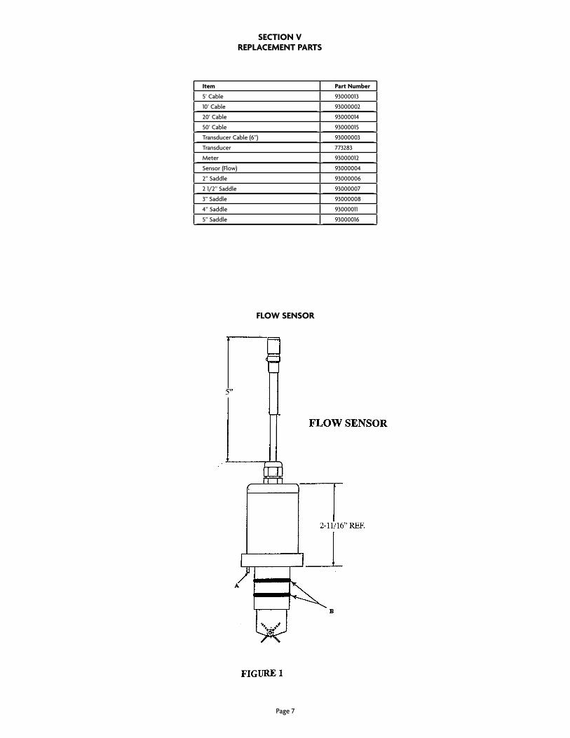
Item Part number
5’ cable 93000013
10’ cable 93000002
20’ cable 93000014
50’ cable 93000015
transducer cable (6”) 93000003
transducer 773283
Meter 93000012
Sensor (Flow) 93000004
2” Saddle 93000006
2 1/2” Saddle 93000007
3” Saddle 93000008
4” Saddle 93000011
5” Saddle 93000016
seCtIon VrePlACement PArts
Flow sensor
page 7

© akron Brass company. 2011 all rights reserved. no portion of this can be reproduced without the express written consent of akron Brass company.
WarrantY anD DiScLaiMer: We warrant akron Brass products for a period of five (5) years after purchase against defects in materials or workmanship. akron Brass will repair or replace product which fails to satisfy this warranty. repair or replacement shall be at the discretion of akron Brass. products must be promptly returned to akron Brass for warranty service.
We will not be responsible for: wear and tear; any improper installation, use, maintenance or storage; negligence of the owner or user; repair or modification after delivery; damage; failure to follow our instructions or recommendations; or anything else beyond our control. We MaKe no WarrantieS, eXpreSS or iMpLieD, otHer tHan tHoSe incLUDeD in tHiS WarrantY StateMent, anD We DiScLaiM anY iMpLieD WarrantY oF MercHantaBiLitY or FitneSS For anY particULar pUrpoSe. Further, we will not be responsible for any consequential, incidental or indirect damages (including, but not limited to, any loss of profits) from any cause whatsoever. no person has authority to change this warranty.
reViSeD: 7/11
pHone: 330.264.5678 or 800.228.1161 i FaX: 330.264.2944 or 800.531.7335 i akronbrass.com
ISO 9001 REGISTERED COMPANY