Embed Size (px)
Citation preview
REV: 05/30/17
Installation & Check-out Guide

Installation & Check-out Guide
2Introduction
Hardware Installation Tips For Professional InstallersZonar equipment will provide years of reliable service if properly installed and maintained. Zonar equipment is typically installed in heavy vehicle applications and is often subjected to extreme temperatures, dust, dirt, vibration, and shock. Proper installation is the critical first step to equipment longevity and optimal performance.This guide is meant to be a general guideline for the professional installer and technician. While we attempt to point out the most common installation questions and issues; common sense, good housekeeping procedures, attention to detail, safety adherence, and technical competence of the professional installer are critical for a successful installation.
Please refer to your specific vehicle manufacturer guidelines for the installation of electrical components and wiring.
Details on operating the Connect and its built-in applications and software are available on the Zonar Support website, detailed later in this guide.
A professional team of Zonar support technicians and engineers are available to answer your installation questions. Contact Zonar at 1-877-843-3847 or by email at [email protected].
Thank you,
Andre J Horochiwsky Senior Technical Support Manager
Installation & Check-out Guide
3Introduction
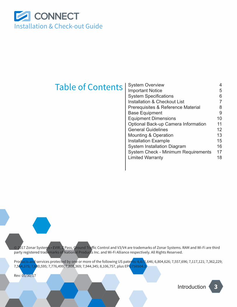
Table of Contents
© 2017 Zonar Systems • EVIR, Z Pass, Ground Traffic Control and V3/V4 are trademarks of Zonar Systems. RAM and Wi-Fi are third party registered trademarks of National Products Inc. and Wi-Fi Alliance respectively. All Rights Reserved.
Products and services protected by one or more of the following US patents: 6,671,646; 6,804,626; 7,557,696; 7,117,121; 7,362,229; 7,564,375; 7,680,595; 7,776,499; 7,808,369; 7,944,345; 8,106,757, plus EP 2756504.3.
Rev: 05/30/17
System Overview 4Important Notice 5System Specifications 6Installation & Checkout List 7Prerequisites & Reference Material 8Base Equipment 9Equipment Dimensions 10Optional Back-up Camera Information 11General Guidelines 12Mounting & Operation 13Installation Example 15System Installation Diagram 16System Check - Minimum Requirements 17Limited Warranty 18
Installation & Check-out Guide
4Introduction
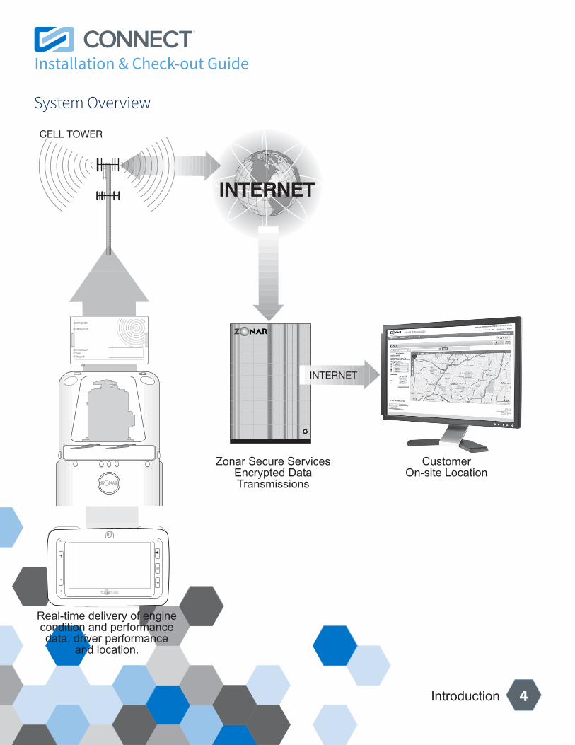
CELL TOWER
INTERNET
Real-time delivery of enginecondition and performance data, driver performance
and location.
Zonar Secure ServicesEncrypted Data Transmissions
CustomerOn-site Location
System Overview
Installation & Check-out Guide
5Introduction
It is the Owner’s sole responsibility to install and use Zonar products in a manner that will not cause accidents, personal injury or property damage. For the purposes of this notice, “Owner”, “you” and “your” means the party (including any person authorized by that party to use and/or install the Product) that has either: (a) purchased the Product; or (b) leased the Product from Zonar Systems, Inc or its related companies. The Owner of this product is solely responsible for observing safe driving practices. The choice, location, and installation of all components of the Product is critical. If installation is not correct, the Product may not perform as its design or specifications indicate. If in doubt, consult with your vehicle’s manufacturer.
Important Notice
Installation & Check-out Guide
6Introduction
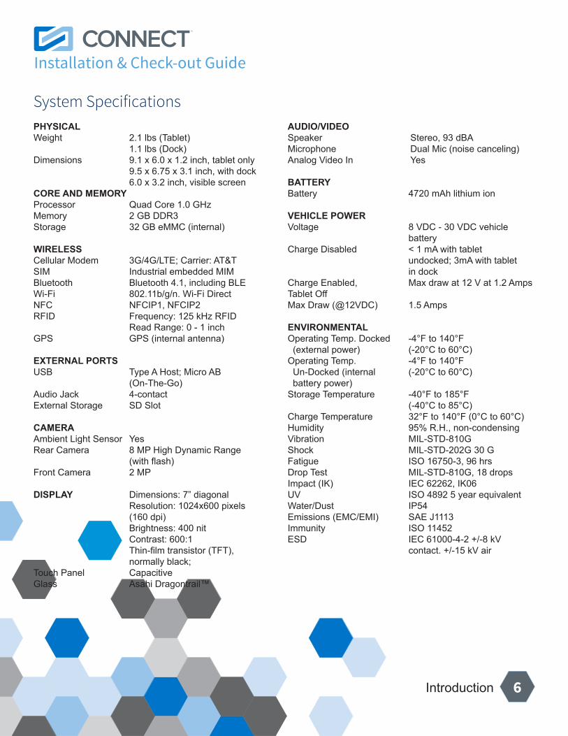
PHYSICALWeight 2.1 lbs (Tablet) 1.1 lbs (Dock) Dimensions 9.1 x 6.0 x 1.2 inch, tablet only 9.5 x 6.75 x 3.1 inch, with dock 6.0 x 3.2 inch, visible screenCORE AND MEMORY Processor Quad Core 1.0 GHz Memory 2 GB DDR3 Storage 32 GB eMMC (internal)
WIRELESS Cellular Modem 3G/4G/LTE; Carrier: AT&T SIM Industrial embedded MIMBluetooth Bluetooth 4.1, including BLE Wi-Fi 802.11b/g/n. Wi-Fi Direct NFC NFCIP1, NFCIP2 RFID Frequency: 125 kHz RFID Read Range: 0 - 1 inch GPS GPS (internal antenna)
EXTERNAL PORTS USB Type A Host; Micro AB (On-The-Go)Audio Jack 4-contact External Storage SD Slot
CAMERA Ambient Light Sensor Yes Rear Camera 8 MP High Dynamic Range (with flash)Front Camera 2 MP
DISPLAY Dimensions: 7” diagonal Resolution: 1024x600 pixels (160 dpi) Brightness: 400 nit Contrast: 600:1 Thin-film transistor (TFT), normally black; Touch Panel Capacitive Glass Asahi Dragontrail™
AUDIO/VIDEO Speaker Stereo, 93 dBA Microphone Dual Mic (noise canceling)Analog Video In Yes
BATTERY Battery 4720 mAh lithium ion
VEHICLE POWERVoltage 8 VDC - 30 VDC vehicle batteryCharge Disabled < 1 mA with tablet undocked; 3mA with tablet in dockCharge Enabled, Max draw at 12 V at 1.2 Amps Tablet Off Max Draw (@12VDC) 1.5 Amps
ENVIRONMENTAL Operating Temp. Docked -4°F to 140°F (external power) (-20°C to 60°C)Operating Temp. -4°F to 140°F Un-Docked (internal (-20°C to 60°C) battery power)Storage Temperature -40°F to 185°F (-40°C to 85°C)Charge Temperature 32°F to 140°F (0°C to 60°C) Humidity 95% R.H., non-condensingVibration MIL-STD-810GShock MIL-STD-202G 30 GFatigue ISO 16750-3, 96 hrs Drop Test MIL-STD-810G, 18 dropsImpact (IK) IEC 62262, IK06UV ISO 4892 5 year equivalentWater/Dust IP54Emissions (EMC/EMI) SAE J1113 Immunity ISO 11452ESD IEC 61000-4-2 +/-8 kV contact. +/-15 kV air
System Specifications
Installation & Check-out Guide
7Introduction
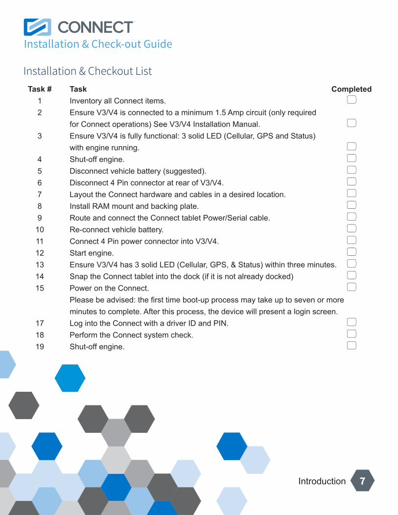
Task # Task Completed 1 Inventory all Connect items. 5 2 Ensure V3/V4 is connected to a minimum 1.5 Amp circuit (only required for Connect operations) See V3/V4 Installation Manual. 5 3 Ensure V3/V4 is fully functional: 3 solid LED (Cellular, GPS and Status) with engine running. 5 4 Shut-off engine. 5 5 Disconnect vehicle battery (suggested). 5 6 Disconnect 4 Pin connector at rear of V3/V4. 5 7 Layout the Connect hardware and cables in a desired location. 5 8 Install RAM mount and backing plate. 5 9 Route and connect the Connect tablet Power/Serial cable. 5 10 Re-connect vehicle battery. 5 11 Connect 4 Pin power connector into V3/V4. 5 12 Start engine. 5 13 Ensure V3/V4 has 3 solid LED (Cellular, GPS, & Status) within three minutes. 5 14 Snap the Connect tablet into the dock (if it is not already docked) 5 15 Power on the Connect. 5 Please be advised: the first time boot-up process may take up to seven or more minutes to complete. After this process, the device will present a login screen. 17 Log into the Connect with a driver ID and PIN. 5 18 Perform the Connect system check. 5 19 Shut-off engine. 5
Installation & Checkout List
Installation & Check-out Guide
8Installation
Reference MaterialZonar’s support website: http://docs.zonarsystems.net.
NOTE: A user name and password are required to access this site.
PrerequisitesThe V3/V4 GPS unit must be fully installed, configured, checked-out, and fully operational prior to installing the Connect.
Please see the “V3/V4 Installation and User Guide” on Zonar’s support website.
Prerequisites & Reference Material
Installation & Check-out Guide
9Installation
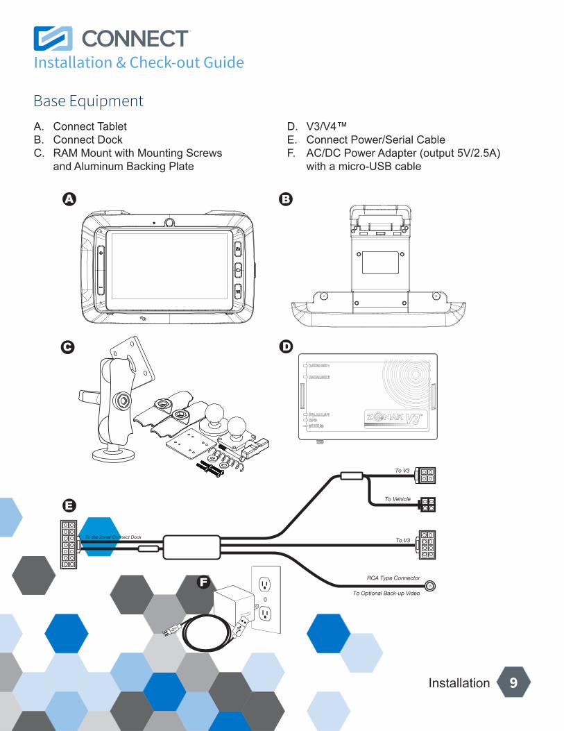
To the Zonar Connect Dock
To V3
To Vehicle
To Optional Back-up Video
RCA Type Connector
To V3
A. Connect TabletB. Connect DockC. RAM Mount with Mounting Screws and Aluminum Backing Plate
D. V3/V4™E. Connect Power/Serial CableF. AC/DC Power Adapter (output 5V/2.5A) with a micro-USB cable
Base Equipment
Installation & Check-out Guide
10Installation
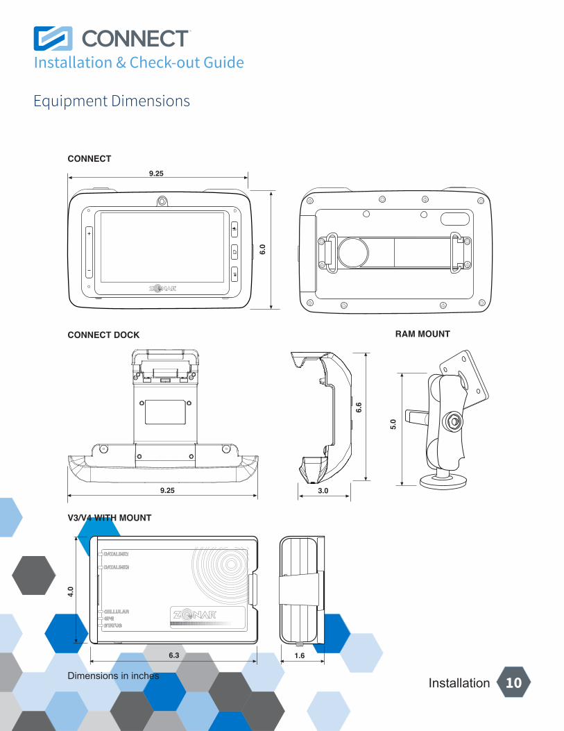
4.0
6.3 1.6
V3/V4 WITH MOUNT
RAM MOUNT
Dimensions in inches
5.0
9.25
9.25
6.6
3.0
CONNECT
CONNECT DOCK
6.0
Equipment Dimensions
Installation & Check-out Guide
11Installation
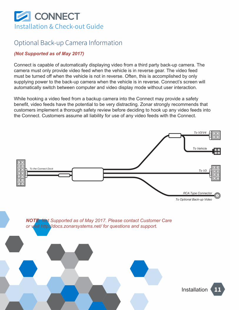
(Not Supported as of May 2017)
Connect is capable of automatically displaying video from a third party back-up camera. The camera must only provide video feed when the vehicle is in reverse gear. The video feed must be turned off when the vehicle is not in reverse. Often, this is accomplished by only supplying power to the back-up camera when the vehicle is in reverse. Connect’s screen will automatically switch between computer and video display mode without user interaction.
While hooking a video feed from a backup camera into the Connect may provide a safety benefit, video feeds have the potential to be very distracting. Zonar strongly recommends that customers implement a thorough safety review before deciding to hook up any video feeds into the Connect. Customers assume all liability for use of any video feeds with the Connect.
To the Connect Dock
To V3/V4
To Vehicle
To Optional Back-up Video
RCA Type Connector
To V3
Optional Back-up Camera Information
NOTE: Not Supported as of May 2017. Please contact Customer Care or visit http://docs.zonarsystems.net/ for questions and support.
Installation & Check-out Guide
12Installation
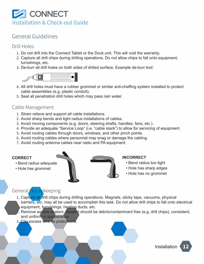
Drill Holes1. Do not drill into the Connect Tablet or the Dock unit. This will void the warranty.2. Capture all drill chips during drilling operations. Do not allow chips to fall onto equipment,
furnishings, etc.3. De-burr all drill holes on both sides of drilled surface. Example de-burr tool:
4. All drill holes must have a rubber grommet or similar anti-chaffing system installed to protect cable assemblies (e.g. plastic conduit).
5. Seal all penetration drill holes which may pass rain water.
Cable Management1. Strain relieve and support all cable installations.2. Avoid sharp bends and tight radius installations of cables.3. Avoid moving components (e.g. doors, steering shafts, handles, fans, etc.).4. Provide an adequate “Service Loop” (i.e. “cable slack”) to allow for servicing of equipment.5. Avoid routing cables through doors, windows, and other pinch points.6. Avoid routing cables where personnel may snag or damage the cabling.7. Avoid routing antenna cables near radio and PA equipment.
CORRECT• Bend radius adequate• Hole has grommet
INCORRECT• Bend radius too tight• Hole has sharp edges• Hole has no grommet
General Housekeeping1. Capture all drill chips during drilling operations. Magnets, sticky tape, vacuums, physical
barriers, etc. may all be used to accomplish this task. Do not allow drill chips to fall onto electrical equipment, furnishings, heating ducts, etc.
2. Remove excess sealant. Sealant should be debris/contaminant free (e.g. drill chips), consistent, and uniform in appearance.
3. Clip excess wire tie protrusions.
General Guidelines
Installation & Check-out Guide
13Installation
Mounting Position Considerations1. Verify placement acceptability with state DOT/Law Enforcement prior to installation.2. Follow all general guidelines on page 12.
Do1. Lay all components out prior to installation to check for cable length and interference issues.2. Choose a location which does not impede driver or co-driver entry.3. Ensure location of the installed Connect does not block driver view (including mirrors and
gauges) or interfere with safe operation of the vehicle’s controls.4. Choose a location which is within easy reach of the driver or co-driver, and within normal line-of-
sight.5. Mount in the vehicle at a convenient height and angle for drivers and co-drivers to access.6. Ensure that the placement of the Connect allows drivers and co-drivers to easily dock and
undock the tablet.7. Ensure the mounting surface is strong enough to support the RAM mount and Connect.
Do Not1. Do not mount the Connect in an area that may interfere with the deployment of an air bag.2. Do not mount the Connect in a location that may impact the driver or co-driver in the event of an
accident or sudden stop.3. Do not mount the Connect in dirty or wet areas.4. Do not mount the Connect in areas of direct sunlight.5. Do not mount the Connect in front of an open AC or heater vent. If unable to install elsewhere,
close the vent the Connect is installed in front of.6. Do not mount the Connect near windows and vents which may pass rain water.7. Avoid mounting the Connect in an area that may limit leg room or where the Connect may likely
be used as a foot or elbow rest, etc.8. Do not mount the Connect below a beverage holder.
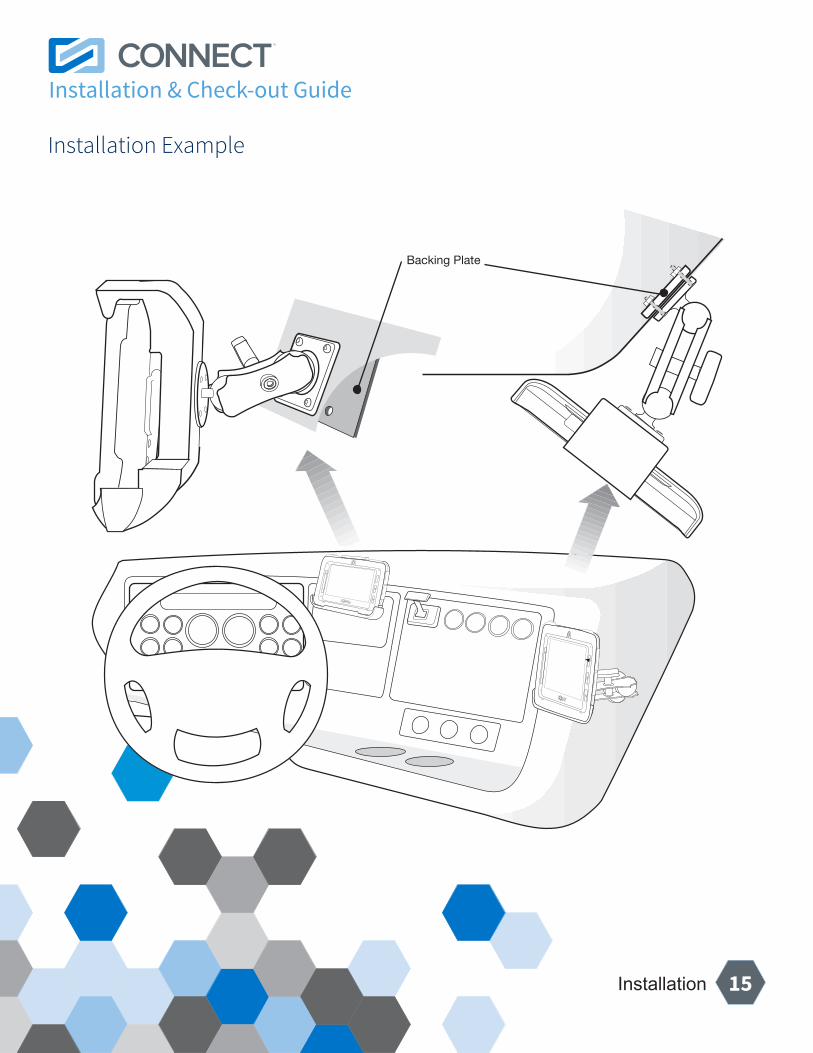
Mounting InstallationRefer to the mounting locations guide (see page 15) for examples of ideal mounting locations. Mounting locations may vary based on the type of vehicle or driver requirements.
1. Attach RAM mount to a location visible and accessible to the driver.2. Use backing plate to secure mount.3. Once mounting is securely installed, dock the Connect.
Mounting & Operation
Installation & Check-out Guide
14Installation
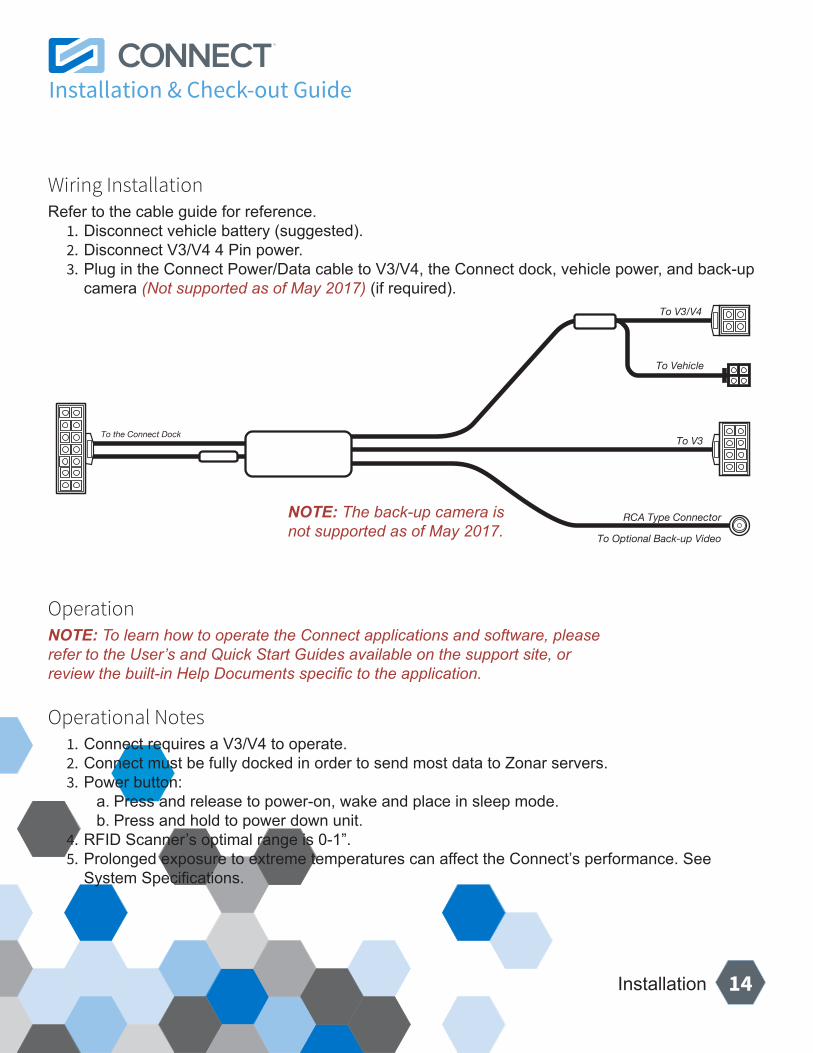
Wiring InstallationRefer to the cable guide for reference.
1. Disconnect vehicle battery (suggested).2. Disconnect V3/V4 4 Pin power.3. Plug in the Connect Power/Data cable to V3/V4, the Connect dock, vehicle power, and back-up
camera (Not supported as of May 2017) (if required).
OperationNOTE: To learn how to operate the Connect applications and software, please refer to the User’s and Quick Start Guides available on the support site, or review the built-in Help Documents specific to the application.
Operational Notes1. Connect requires a V3/V4 to operate.2. Connect must be fully docked in order to send most data to Zonar servers.3. Power button:
a. Press and release to power-on, wake and place in sleep mode.b. Press and hold to power down unit.
4. RFID Scanner’s optimal range is 0-1”.5. Prolonged exposure to extreme temperatures can affect the Connect’s performance. See
System Specifications.
To the Connect Dock
To V3/V4
To Vehicle
To Optional Back-up Video
RCA Type Connector
To V3
NOTE: The back-up camera is not supported as of May 2017.
Installation & Check-out Guide
15Installation
Backing Plate
Installation Example
Installation & Check-out Guide
16Installation
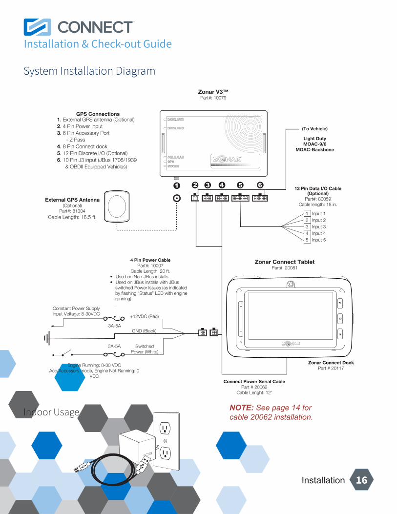
External GPS Antenna(Optional)
Part#: 81304Cable Length: 16.5 ft.
SwitchedPower (White)
GND (Black)
1 Input 12 Input 23 Input 3 4 Input 45 Input 5
4 Pin Power CablePart#: 10007
Cable Length: 20 ft.• Used on Non-JBus installs• Used on JBus installs with JBus
switched Power Issues (as indicated by flashing “Status” LED with engine running)
Constant Power SupplyInput Voltage: 8-30VDC
Engine Running: 8-30 VDCAcc/Accessory mode, Engine Not Running: 0
VDC
+12VDC (Red)
Zonar V3™Part#: 10079
3A-5A
12 Pin Data I/O Cable(Optional)
Part#: 80059Cable length: 18 in.
(To Vehicle)
Light DutyMOAC-9/6
MOAC-Backbone
GPS Connections1. External GPS antenna (Optional)2. 4 Pin Power Input3. 6 Pin Accessory Port - Z Pass4. 8 Pin Connect dock5. 12 Pin Discrete I/O (Optional)6. 10 Pin J3 input (JBus 1708/1939
& OBDII Equipped Vehicles)
3A-5A
Zonar Connect TabletPart#: 20081
Zonar Connect DockPart # 20117
Connect Power Serial CablePart # 20062
Cable Lenght: 12’
Indoor Usage NOTE: See page 14 for cable 20062 installation.
System Installation Diagram
Installation & Check-out Guide
17Checkout
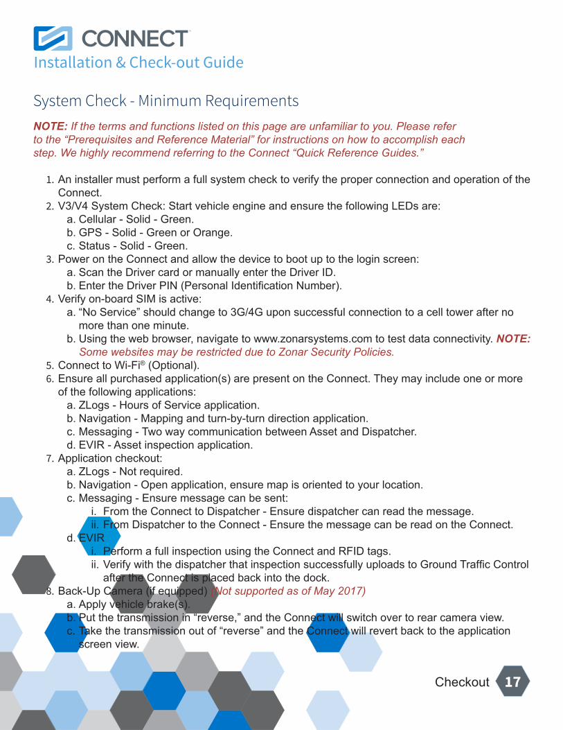
NOTE: If the terms and functions listed on this page are unfamiliar to you. Please refer to the “Prerequisites and Reference Material” for instructions on how to accomplish each step. We highly recommend referring to the Connect “Quick Reference Guides.”
1. An installer must perform a full system check to verify the proper connection and operation of the Connect.
2. V3/V4 System Check: Start vehicle engine and ensure the following LEDs are:a. Cellular - Solid - Green.b. GPS - Solid - Green or Orange.c. Status - Solid - Green.
3. Power on the Connect and allow the device to boot up to the login screen:a. Scan the Driver card or manually enter the Driver ID.b. Enter the Driver PIN (Personal Identification Number).
4. Verify on-board SIM is active:a. “No Service” should change to 3G/4G upon successful connection to a cell tower after no
more than one minute.b. Using the web browser, navigate to www.zonarsystems.com to test data connectivity. NOTE:
Some websites may be restricted due to Zonar Security Policies. 5. Connect to Wi-Fi® (Optional).6. Ensure all purchased application(s) are present on the Connect. They may include one or more
of the following applications:a. ZLogs - Hours of Service application.b. Navigation - Mapping and turn-by-turn direction application.c. Messaging - Two way communication between Asset and Dispatcher.d. EVIR - Asset inspection application.
7. Application checkout:a. ZLogs - Not required.b. Navigation - Open application, ensure map is oriented to your location.c. Messaging - Ensure message can be sent:
i. From the Connect to Dispatcher - Ensure dispatcher can read the message.ii. From Dispatcher to the Connect - Ensure the message can be read on the Connect.
d. EVIRi. Perform a full inspection using the Connect and RFID tags.ii. Verify with the dispatcher that inspection successfully uploads to Ground Traffic Control
after the Connect is placed back into the dock.8. Back-Up Camera (if equipped) (Not supported as of May 2017)
a. Apply vehicle brake(s).b. Put the transmission in “reverse,” and the Connect will switch over to rear camera view.c. Take the transmission out of “reverse” and the Connect will revert back to the application
screen view.
System Check - Minimum Requirements
Installation & Check-out Guide
18Warranty & Notices - FCC Compliance
LIMITED HARDWARE WARRANTY FOR PURCHASED HARDWARE: Zonar warrants that the serialized Hardware elements of any Zonar Offerings delivered by Zonar shall be free from all material defects in workmanship under normal use and service. Zonar’s warranty period for such serialized Hardware (V series GPS units, ZTrak GPS units, EVIR 2010 handheld’s, Zonar Tablets, Z PASS readers) is as follows: V3/V4 Series HD GPS Product Line – 5 Years (V3/V4, and V3/V4R only; V3/V4i); EVIR and all Other Serialized Hardware – 1 Year. The warranty period runs from the date of shipment, and any replacement hardware provided under warranty will be covered under warranty for the remainder of the warranty term based on the shipment date for the original equipment. Provided that such Hardware is used and handled as intended and in accordance with this Agreement, and that Customer provides Zonar with notice within the applicable warranty coverage period, as Customer’s sole and exclusive remedy, Zonar will replace any failed or functionally impaired Hardware with equivalent Hardware in terms of performance and functionality. This warranty does not apply to any Hardware that has been misused, altered, willfully abused or that has been subject to water or other environmental damage or that has been damaged due to improper installation by Customer or its agents. Hardware installations must follow Zonar’s equipment-specific installation guidelines to qualify for the foregoing warranty. If Hardware is determined by Zonar to be damaged due to any of the aforementioned causes, Customer will be charged the price of a refurbished unit plus shipping and handling. Return of any Hardware requires a Return Material Authorization (“RMA”) number. All RMA’s must be pre-authorized by Zonar Customer Care at: E-mail: [email protected]. Phone: 1(877)-THE-EVIR. Ancillary hardware such as mounts, brackets, and cables are excluded from the above warranty.
Warning: (Part 15.21)
Changes or modifications not expressly approved by Zonar Systems could void the user’s authority to operate the equipment.
Limited Warranty
Installation & Check-out Guide
19Warranty & Notices - FCC Compliance
FCC Warning
This equipment has been tested and found to comply with the limits for a Class B digital device, pursuant to part 15 of the FCC Rules. These limits are designed to provide reasonable protection against harmful interference in a residential installation. This equipment generates, uses and can radiate radio frequency energy and, if not installed and used in accordance with the instructions, may cause harmful interference to radio communications. However, there is no guarantee that interference will not occur in a particular installation. If this equipment does cause harmful interference to radio or television reception, which can be determined by turning the equipment off and on, the user is encouraged to try to correct the interference by one or more of the following measures:
• Reorient or relocate the receiving antenna.• Increase the separation between the equipment and receiver.• Connect the equipment into an outlet on a circuit different from that to which the receiver is connected.
Consult the dealer or an experienced radio/TV technician for help.• Any changes or modifications not expressly approved by the party responsible for compliance could void the
authority to operate equipment.• This device and its antenna must not be co-located or operating in conjunction with any other antenna or
transmitter.• End-users and installers must be provided with antenna installation instructions and transmitter operating
conditions for satisfying RF exposure compliance.• For product available in the USA/Canada market, only channel 1~11 can be operated. Selection of other
channels is not possible.
FCC RF Radiation Exposure StatementPortable DeviceThis equipment complies with FCC RF radiation exposure limits set forth for an uncontrolled environment for body-worn configuration in direct contact to the phantom.
IC WarningRSS-Gen Issue 4 8.4This device complies with Industry Canada’s license-exempt RSSs. Operation is subject to the following two conditions: (1) This device may not cause interference; and (2) This device must accept any interference, including interference that may cause undesired operation of the device.Le présent appareil est conforme aux CNR d’Industrie Canada applicables aux appareils radio exempts de licence. L’exploitation est autorisée aux deux conditions suivantes : (1) l’appareil ne doit pas produire de brouillage, et (2) l’utilisateur de l’appareil doit accepter tout brouillage radioélectrique subi, même si le brouillage est susceptible d’en compromettre le fonctionnement.Industry Canada ICES-003 Compliance LabelCAN ICES-3 (B)/NMB-3(B)Co-locatedThis device and its antenna(s) must not be co-located or operating in conjunction with any other antenna or transmitter.Cet appareil et son antenne (s) ne doivent pas être situés ou fonctionner en conjonction avec une autre antenne ou émetteur.