Embed Size (px)
Citation preview
1
Installation Guide Z206281-0A03/2012
EM3500-ENC and EM3500-KEYEnclosure and Locking Mechanism for EM35xx Meters
RoHSCompliant
INTRODUCTIONThe EM3500-ENC enclosure offers a mounting option for EM35xx Series energy meters that helps protect from tampering and the elements. The enclosure is equipped with DIN rail mounting hardware for easy installation and a NEMA 4X rating for durability. The optional EM3500-KEY keylock provides additional security from unwanted tampering. The EM3500-ENC and EM3500-KEY are sold as separate units.This document describes the installation of the EM35xx meter with both accessories.
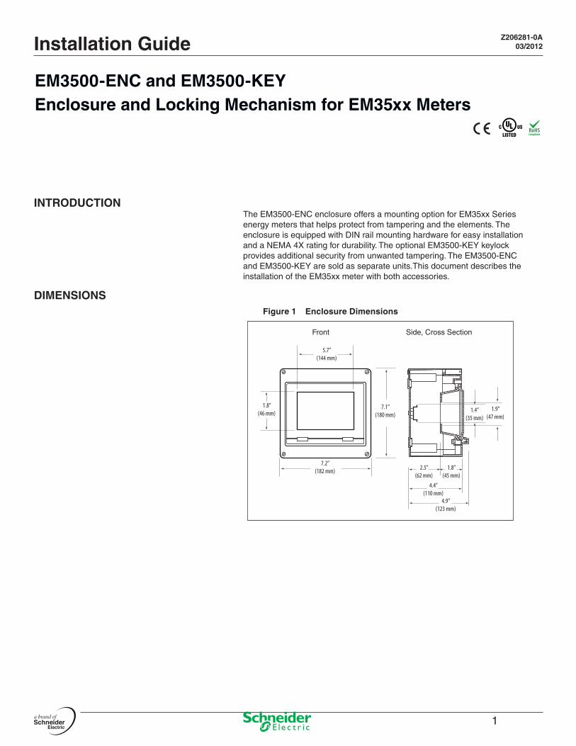
DIMENSIONSFigure 1 Enclosure Dimensions
7.2”(182 mm)
7.1”(180 mm)
5.7”(144 mm)
1.8”(46 mm)
4.9”(123 mm)
4.4”(110 mm)
2.5”(62 mm)
1.8”(45 mm)
1.9”(47 mm)
1.4”(35 mm)
Front Side, Cross Section
2© 2012 Schneider Electric All Rights Reserved.
Z206281-0A03/2012
EM3500-ENC and EM3500-KEYParts of the EM3500_ENC
PARTS OF THE EM3500_ENC AND EM3500_KEY
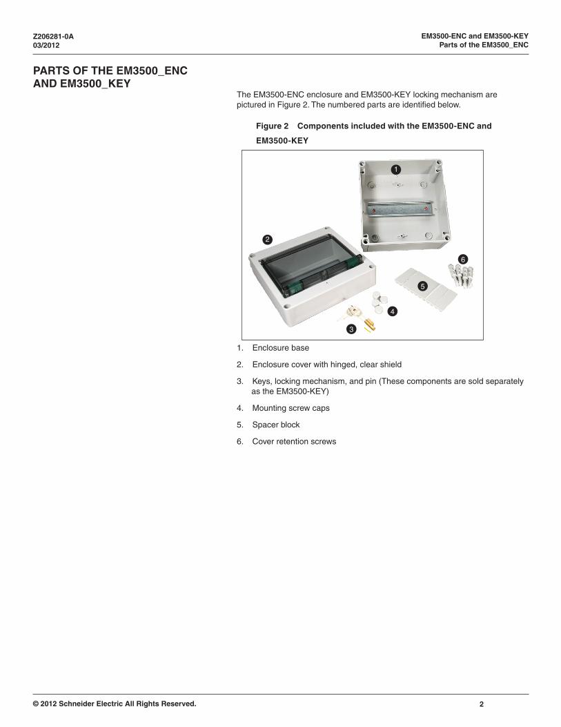
The EM3500-ENC enclosure and EM3500-KEY locking mechanism are pictured in Figure 2. The numbered parts are identified below.
Figure 2 Components included with the EM3500-ENC and
EM3500-KEY
1
2
3
4
5
6
1. Enclosure base
2. Enclosure cover with hinged, clear shield
3. Keys, locking mechanism, and pin (These components are sold separately as the EM3500-KEY)
4. Mounting screw caps
5. Spacer block
6. Cover retention screws
3 © 2012 Schneider Electric All Rights Reserved.
EM3500-ENC and EM3500-KEYinstallation
Z206281-0A03/2012
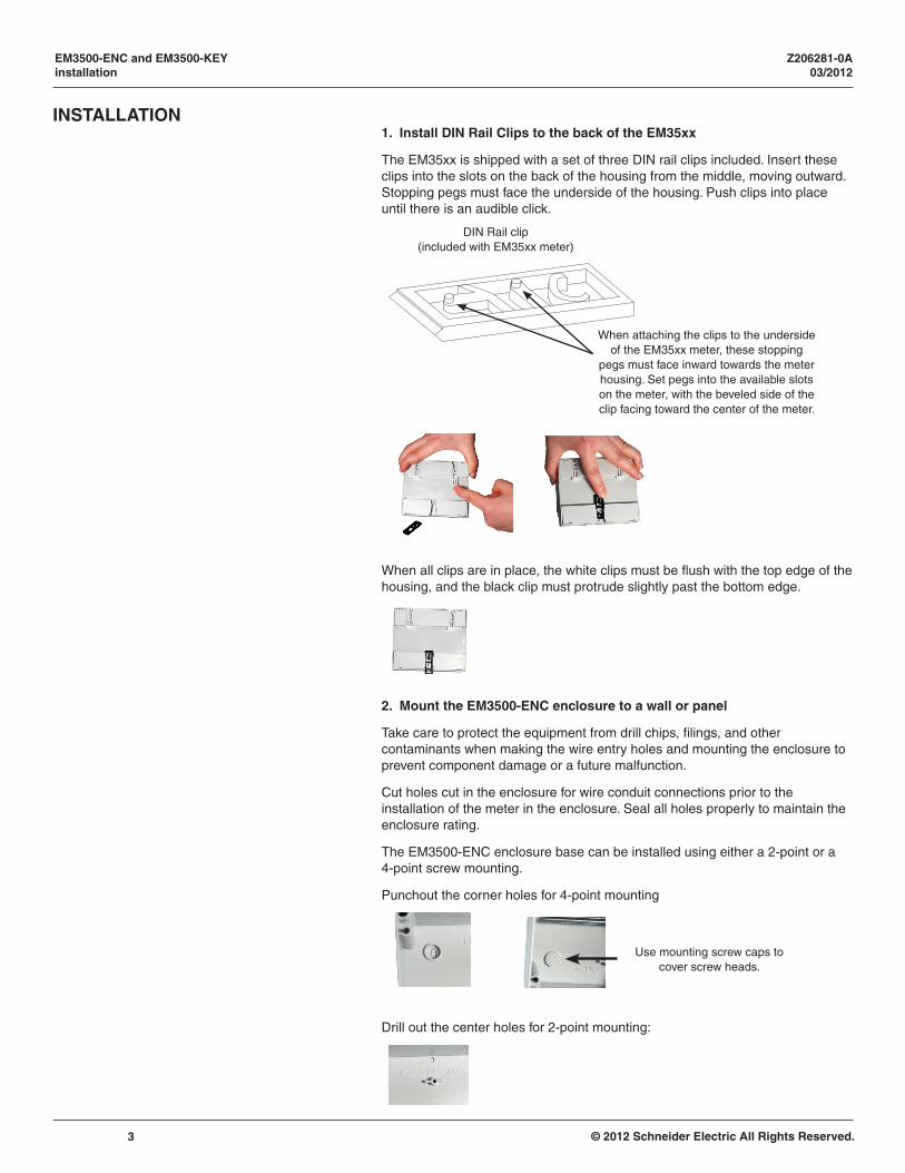
INSTALLATION1. Install DIN Rail Clips to the back of the EM35xx
The EM35xx is shipped with a set of three DIN rail clips included. Insert these clips into the slots on the back of the housing from the middle, moving outward. Stopping pegs must face the underside of the housing. Push clips into place until there is an audible click.
DIN Rail clip(included with EM35xx meter)
When attaching the clips to the underside of the EM35xx meter, these stopping
pegs must face inward towards the meter housing. Set pegs into the available slots on the meter, with the beveled side of the clip facing toward the center of the meter.
When all clips are in place, the white clips must be flush with the top edge of the housing, and the black clip must protrude slightly past the bottom edge.
2. Mount the EM3500-ENC enclosure to a wall or panel
Take care to protect the equipment from drill chips, filings, and other contaminants when making the wire entry holes and mounting the enclosure to prevent component damage or a future malfunction.
Cut holes cut in the enclosure for wire conduit connections prior to the installation of the meter in the enclosure. Seal all holes properly to maintain the enclosure rating.
The EM3500-ENC enclosure base can be installed using either a 2-point or a 4-point screw mounting.
Punchout the corner holes for 4-point mounting
Use mounting screw caps to cover screw heads.
Drill out the center holes for 2-point mounting:
4© 2012 Schneider Electric All Rights Reserved.
Z206281-0A03/2012
EM3500-ENC and EM3500-KEYinstallation
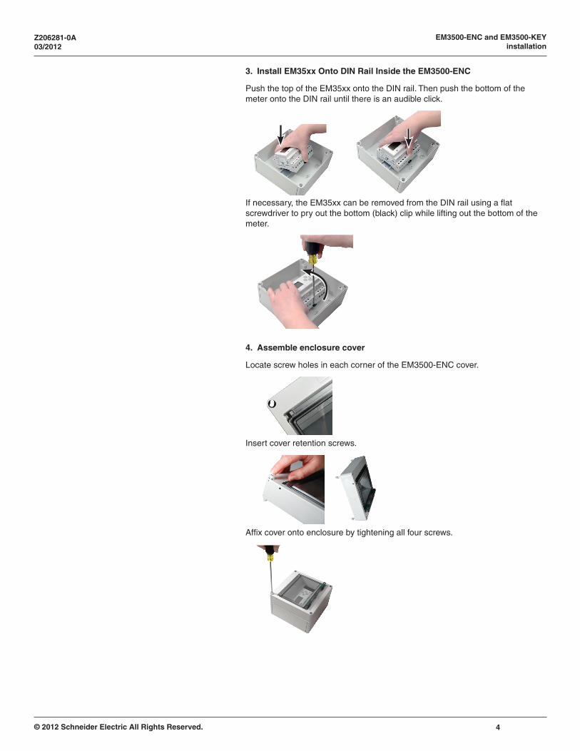
3. Install EM35xx Onto DIN Rail Inside the EM3500-ENC
Push the top of the EM35xx onto the DIN rail. Then push the bottom of the meter onto the DIN rail until there is an audible click.
If necessary, the EM35xx can be removed from the DIN rail using a flat screwdriver to pry out the bottom (black) clip while lifting out the bottom of the meter.
4. Assemble enclosure cover
Locate screw holes in each corner of the EM3500-ENC cover.
Insert cover retention screws.
Affix cover onto enclosure by tightening all four screws.
5 © 2012 Schneider Electric All Rights Reserved.
EM3500-ENC and EM3500-KEYinstallation
Z206281-0A03/2012
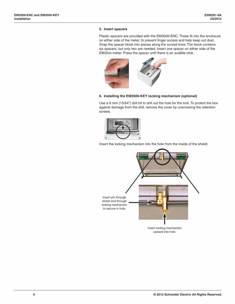
5. Insert spacers
Plastic spacers are provided with the EM3500-ENC. These fit into the enclosure on either side of the meter, to prevent finger access and help keep out dust. Snap the spacer block into pieces along the scored lines. The block contains six spacers, but only two are needed. Insert one spacer on either side of the EM35xx meter. Press the spacer until there is an audible click.
6. Installing the EM3500-KEY locking mechanism (optional)
Use a 6 mm (15/64”) drill bit to drill out the hole for the lock. To protect the box against damage from the drill, remove the cover by unscrewing the retention screws.
Insert the locking mechanism into the hole from the inside of the shield.
Insert locking mechanism upward into hole.
Insert pin through shield and through locking mechanism to secure in hole.
ION, Modbus, and PowerLogic are either trademarks or registered trademarks of Schneider Electric in France, the USA and other countries. Other trademarks used are the property of their respective owners.Electrical equipment should be installed, operated, serviced, and maintained only by qualified personnel. No responsibility is assumed by Schneider Electric for any conse-quences arising out of the use of this material.Z206281-0A 03/2012© 2012 Schneider Electric. All Rights Reserved.
EM3500-ENC and EM3500-KEYInstallation Guide
Schneider Electric295 Tech Park Dr. Suite 100La Vergne TN, 37086
For technical support:[email protected](00) + 1 250 544 3010
Contact your local Schneider Electric sales representative for assistance or go to www.schneider-electric.com
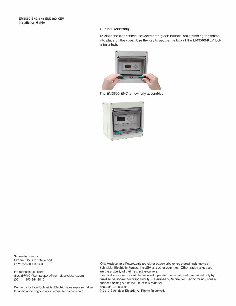
7. Final Assembly
To close the clear shield, squeeze both green buttons while pushing the shield into place on the cover. Use the key to secure the lock (if the EM3500-KEY lock is installed).
The EM3500-ENC is now fully assembled.