Embed Size (px)
Citation preview
INSTALLATION GUIDE
CONTENTS 1. Overview 2. Tools 3. Disassembly 4. Inspection and Cleaning 5. PreInstallation 6. Installation 7. Testing 8. Reassembly 9. Troubleshooting 10. Reference
DISCLAIMER BadAss Consoles is not responsible for any problems or damage ( including but not limited to GCVideo, Monitors, TVs, Consoles, Audio Amps/Headunits, Controllers, other audio/video devices, electrical shock, and/or fire) resulting from failed installation and/or unsafe installation methods. Due to these possible risks and/or hazards, installation service is offered at a reasonable low cost.
INSTALLATION GUIDE
Overview
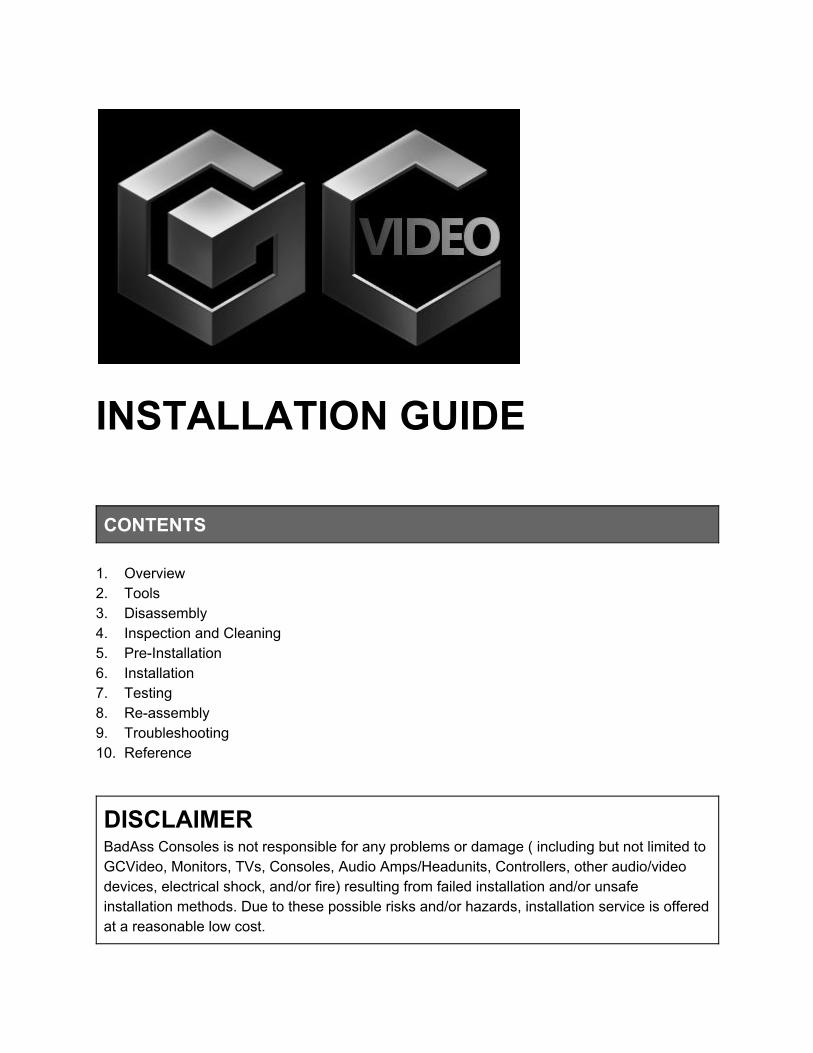
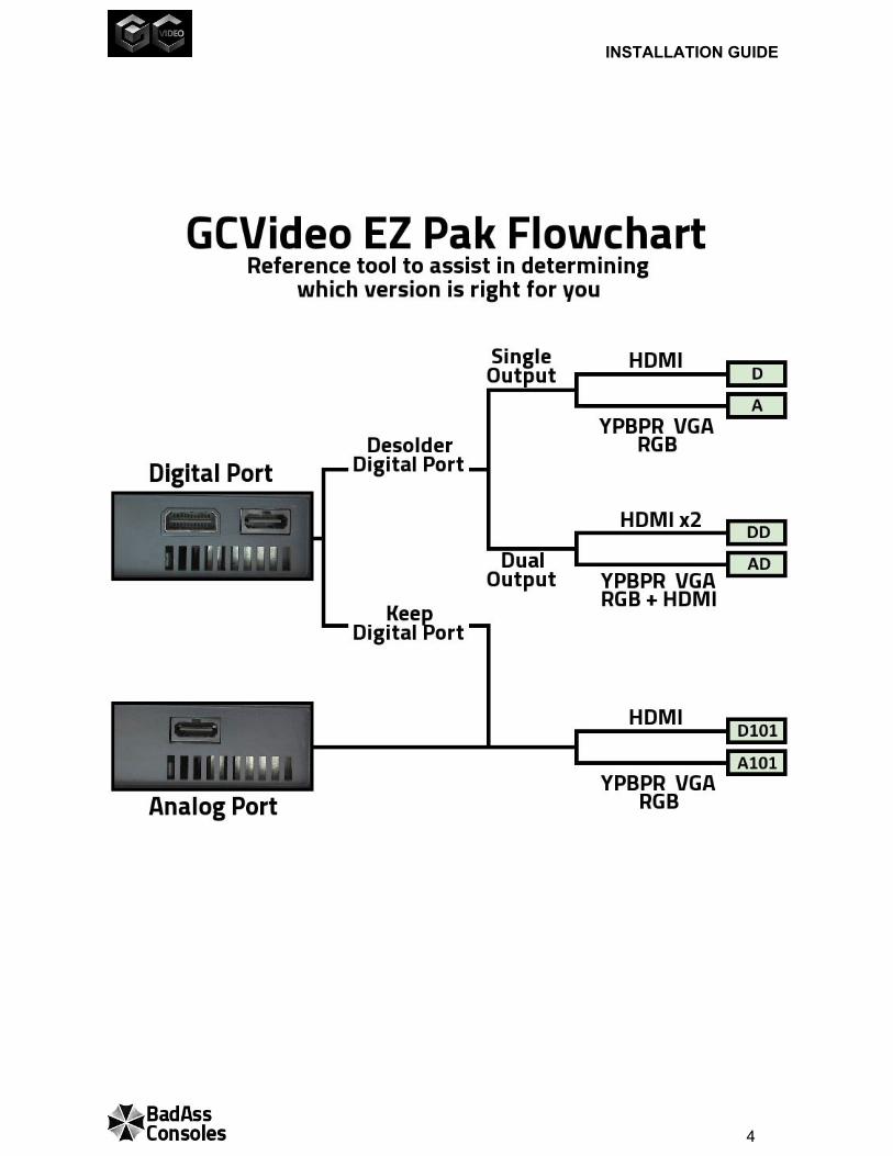
GCVideo is a custom FPGA hardware solution for all versions and all regions of GameCube to display up to 480p/576p video resolution using VGA, Component, RGBs, or HDMI cables to gain improved clarity, sharper details, and improved color separation which was previously capable only using the official GameCube Component cable. Two versions of GCVideo exist, one version for Analog video output and a second version for Digital video output. There are also various EZ Pak styles available for GCVideo which will determine installation method. Depending on prefered style of GCVideo chosen, desoldering of the Digital Port may or may not be required.
GCVideo EZ Pak Comparisons
Style Video Type Digital Port Desoldering
Back Panel Case Cut
DOL001 Compatible
DOL101 Compatible
A
YPBPR,VGA,
RGBs
D
HDMI
A101
YPBPR,VGA
RGBs
D101
HDMI
AD
YPBPR,VGA, RGBs,HDMI
DD
HDMI x2
2
INSTALLATION GUIDE
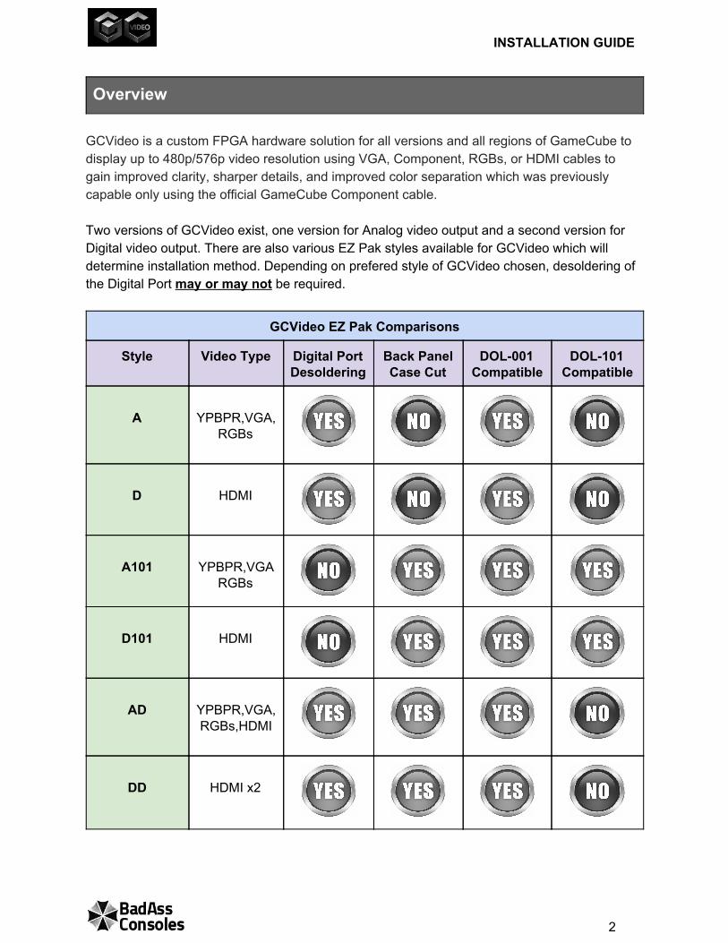
Mount Locations for GCVideo EZ Pak
Style Mount Location GC version
A D
DOL001 Digital Port Removed
A101 D101
DOL101
DOL001 with
Digital Port
AD DD
DOL001 Digital Port Removed
3
INSTALLATION GUIDE
4
INSTALLATION GUIDE
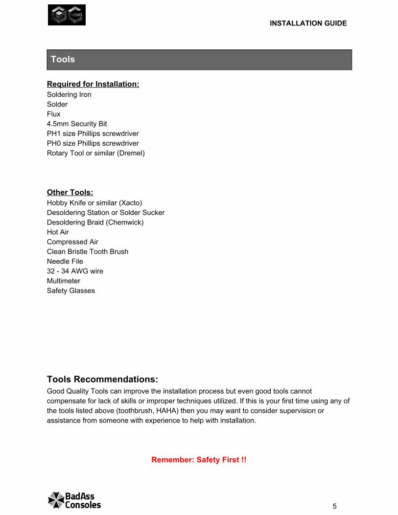
Tools
Required for Installation: Soldering Iron Solder Flux 4.5mm Security Bit PH1 size Phillips screwdriver PH0 size Phillips screwdriver Rotary Tool or similar (Dremel) Other Tools: Hobby Knife or similar (Xacto) Desoldering Station or Solder Sucker Desoldering Braid (Chemwick) Hot Air Compressed Air Clean Bristle Tooth Brush Needle File 32 34 AWG wire Multimeter Safety Glasses Tools Recommendations: Good Quality Tools can improve the installation process but even good tools cannot compensate for lack of skills or improper techniques utilized. If this is your first time using any of the tools listed above (toothbrush, HAHA) then you may want to consider supervision or assistance from someone with experience to help with installation.
Remember: Safety First !!
5
INSTALLATION GUIDE
Soldering Iron GameCube is RoHS compliant, this means LeadFree solder was used to manufacture. LeadFree solder requires higher heat temperatures and higher power soldering stations to melt the solder. 10$ “Lightning Rod” irons do melt Lead solder but are not so great when trying to heat up LeadFree solder, especially those located on the GameCubes massive GND (ground) plane. With enough time passed, the heat applied from a “Lightening Rod” can possibly melt the solder but also introduces the risk of lifting a solder pad from the Mainboard. Most any temperature controlled soldering stations with at least 60 watts of power should suffice. Some clone soldering stations may not perform as well as original models but should at least outperform any typical “lightning rod” iron. Flux A major benefit for using flux is to help with heat transfer between the melted solder, pad, and pin ( or component ) to allow the solder to flow creating a more secure solder joint while also preventing oxidation. Since GCVideo utilizes a Flex Cable it is highly recommended to use flux when soldering the PCB onto the mainboard. There are various types of flux available for use. Due to ease of use, MG Chemicals Rosin Flux is the safest choice since it can be cleaned off with 99% isopropyl alcohol, is noncorrosive and nonconductive. Flux has a limited shelf life and should be stored in a temperature controlled environment. One key consideration with flux is the source of purchase. Ensure any purchase is from an authorized retailer or a reputable and trusted seller. Multimeter A great tool to check and double check connections after installation and for troubleshooting if required. Since approximately 12VDC is the maximum voltage present on the GameCube, just about any multimeter would suffice as long as it allows for measuring DC voltage and Continuity test preferably with a fast responsive audible beep. Remember: most multimeters have autoshutoff after 15 minutes which can cause minor inconveniences during testing.
6
INSTALLATION GUIDE
Desoldering Depending on prefered style for installation of GCVideo, desoldering of the Digital Port may be required. The main concerns involving removal of the Digital Port is to accomplish the task without accidental trace damage or pads lifting off the circuit board. The Digital Port is protected by a large metal housing connected to the GND plane which will sink heat from an iron with poor thermal recovery limiting the iron’s ability to apply enough heat to clear the pad. TIP: Keep in mind it is not necessary to clear the holes of solder since the Flex Cable attaches to the surface of the pad only. Nice and smooth pads are prefered but not absolutely required. High Power Desoldering Station is by far the easiest and safest method for removing the Digital Port. Hot Air can be used for removing the Digital Port but typically requires a much higher heat applied onto the board for an extended length of time due to the heat sink effect caused by the Digital Port’s metal housing. The Air applied must cover a wide range or fast back and forth continuous motion to heat the entire Digital Port area. This process can lead to the possibility of nearby components being blown off the board or the continuous stream of hot air can lead to warping the Mainboard. (YES this can happen) Solder Suckers suck. This is what they were designed to do. Using the solder iron to heat the pin, pad, and melt the solder, a spring loaded Solder Sucker is placed over the molten solder and with a press of a button a mini “vacuum effect” is created by releasing the spring retainer causing a negative pressure to remove solder. The recoil from unloading of the spring causes a somewhat violent force applied onto the Mainboard pads which has been known to cause accidental pad and trace damage. Desoldering Braid is comprised of fine strands of copper wire woven together to make a braid which will wick up (absorb) solder. This is a somewhat tedious effort but can get the job done if the iron can apply enough heat to the solder, pin, pad, and account for the heat sinking from the extra copper in the Desoldering Braid. Flux can help with this process but greater risk of damage occurs if an iron has to be applied for an extended amount of time. Dremel and Cutters is a very unsafe method which can destroy your Mainboard if you do not know what you are doing or have bad control of the cutting blade. The goal is to cut a few key points on the Digital Port housing allowing it to partially separate from the Mainboard. With the digital port connector bent up away from the Mainboard, Cutters can be used to cut the pins allowing easier removal. This method is not recommended for removing the Digital Port unless you’ve got some big balls. You have been warned!!
7
INSTALLATION GUIDE
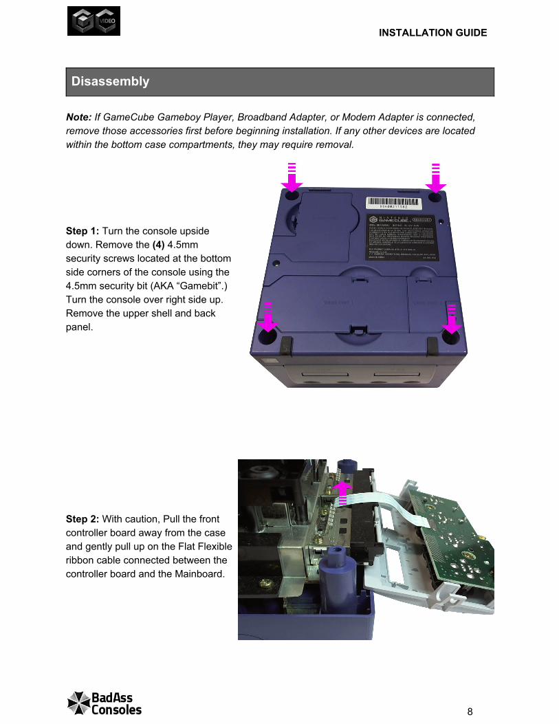
Disassembly Note: If GameCube Gameboy Player, Broadband Adapter, or Modem Adapter is connected, remove those accessories first before beginning installation. If any other devices are located within the bottom case compartments, they may require removal. Step 1: Turn the console upside down. Remove the (4) 4.5mm security screws located at the bottom side corners of the console using the 4.5mm security bit (AKA “Gamebit”.) Turn the console over right side up. Remove the upper shell and back panel. Step 2: With caution, Pull the front controller board away from the case and gently pull up on the Flat Flexible ribbon cable connected between the controller board and the Mainboard.
8
INSTALLATION GUIDE
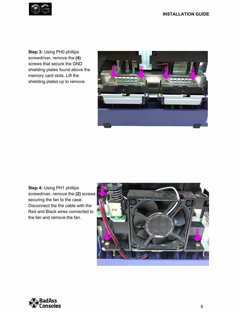
Step 3: Using PH0 phillips screwdriver, remove the (4) screws that secure the GND shielding plates found above the memory card slots. Lift the shielding plates up to remove. Step 4: Using PH1 phillips screwdriver, remove the (2) screws securing the fan to the case. Disconnect the the cable with the Red and Black wires connected to the fan and remove the fan.
9
INSTALLATION GUIDE
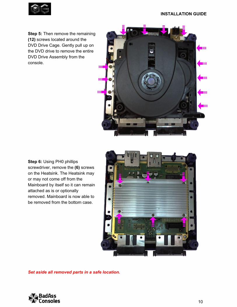
Step 5: Then remove the remaining (12) screws located around the DVD Drive Cage. Gently pull up on the DVD drive to remove the entire DVD Drive Assembly from the console. Step 6: Using PH0 phillips screwdriver, remove the (6) screws on the Heatsink. The Heatsink may or may not come off from the Mainboard by itself so it can remain attached as is or optionally removed. Mainboard is now able to be removed from the bottom case. Set aside all removed parts in a safe location.
10
INSTALLATION GUIDE
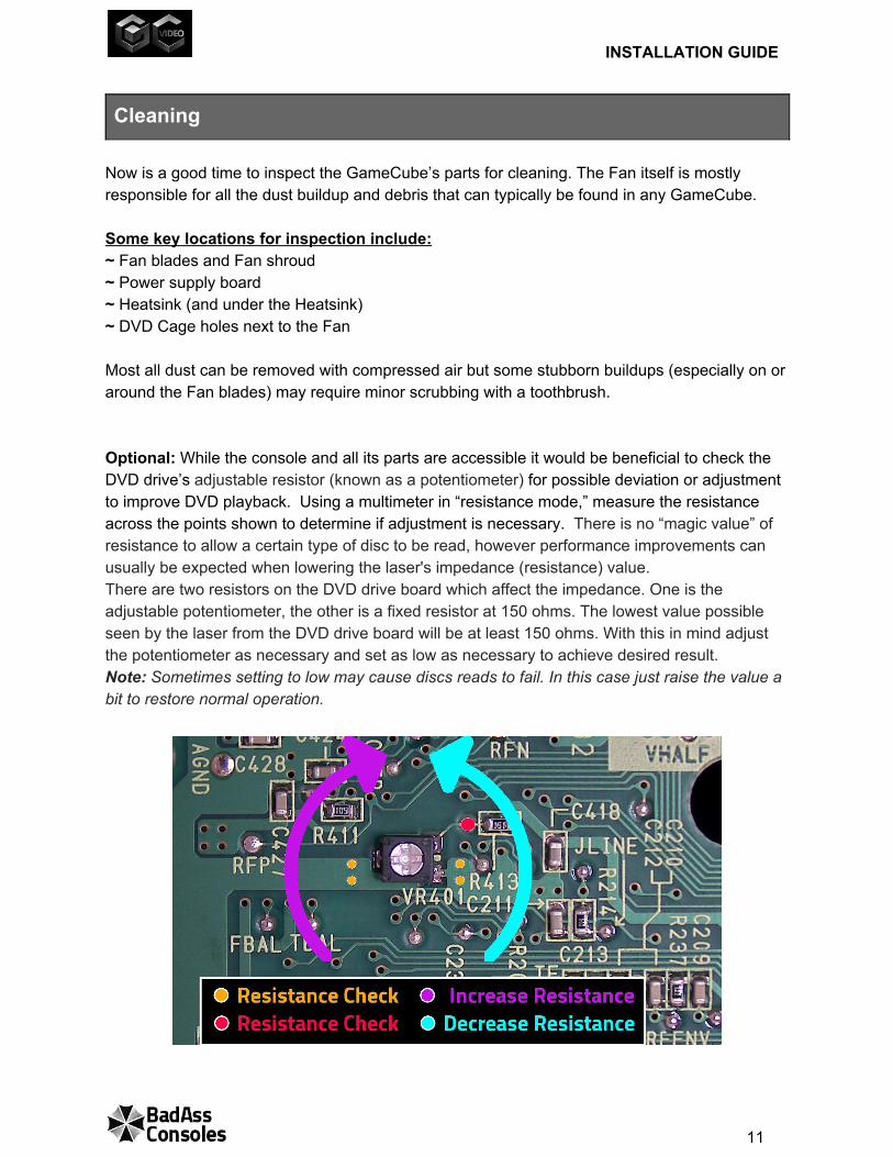
Cleaning Now is a good time to inspect the GameCube’s parts for cleaning. The Fan itself is mostly responsible for all the dust buildup and debris that can typically be found in any GameCube. Some key locations for inspection include: ~ Fan blades and Fan shroud ~ Power supply board ~ Heatsink (and under the Heatsink) ~ DVD Cage holes next to the Fan Most all dust can be removed with compressed air but some stubborn buildups (especially on or around the Fan blades) may require minor scrubbing with a toothbrush. Optional: While the console and all its parts are accessible it would be beneficial to check the DVD drive’s adjustable resistor (known as a potentiometer) for possible deviation or adjustment to improve DVD playback. Using a multimeter in “resistance mode,” measure the resistance across the points shown to determine if adjustment is necessary. There is no “magic value” of resistance to allow a certain type of disc to be read, however performance improvements can usually be expected when lowering the laser's impedance (resistance) value. There are two resistors on the DVD drive board which affect the impedance. One is the adjustable potentiometer, the other is a fixed resistor at 150 ohms. The lowest value possible seen by the laser from the DVD drive board will be at least 150 ohms. With this in mind adjust the potentiometer as necessary and set as low as necessary to achieve desired result. Note: Sometimes setting to low may cause discs reads to fail. In this case just raise the value a bit to restore normal operation.
11
INSTALLATION GUIDE
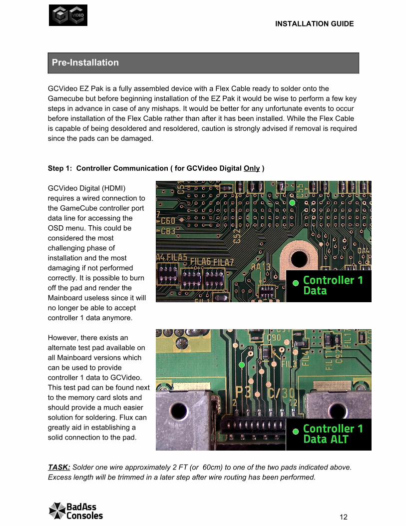
PreInstallation GCVideo EZ Pak is a fully assembled device with a Flex Cable ready to solder onto the Gamecube but before beginning installation of the EZ Pak it would be wise to perform a few key steps in advance in case of any mishaps. It would be better for any unfortunate events to occur before installation of the Flex Cable rather than after it has been installed. While the Flex Cable is capable of being desoldered and resoldered, caution is strongly advised if removal is required since the pads can be damaged. Step 1: Controller Communication ( for GCVideo Digital Only ) GCVideo Digital (HDMI) requires a wired connection to the GameCube controller port data line for accessing the OSD menu. This could be considered the most challenging phase of installation and the most damaging if not performed correctly. It is possible to burn off the pad and render the Mainboard useless since it will no longer be able to accept controller 1 data anymore. However, there exists an alternate test pad available on all Mainboard versions which can be used to provide controller 1 data to GCVideo. This test pad can be found next to the memory card slots and should provide a much easier solution for soldering. Flux can greatly aid in establishing a solid connection to the pad. TASK: Solder one wire approximately 2 FT (or 60cm) to one of the two pads indicated above. Excess length will be trimmed in a later step after wire routing has been performed.
12
INSTALLATION GUIDE
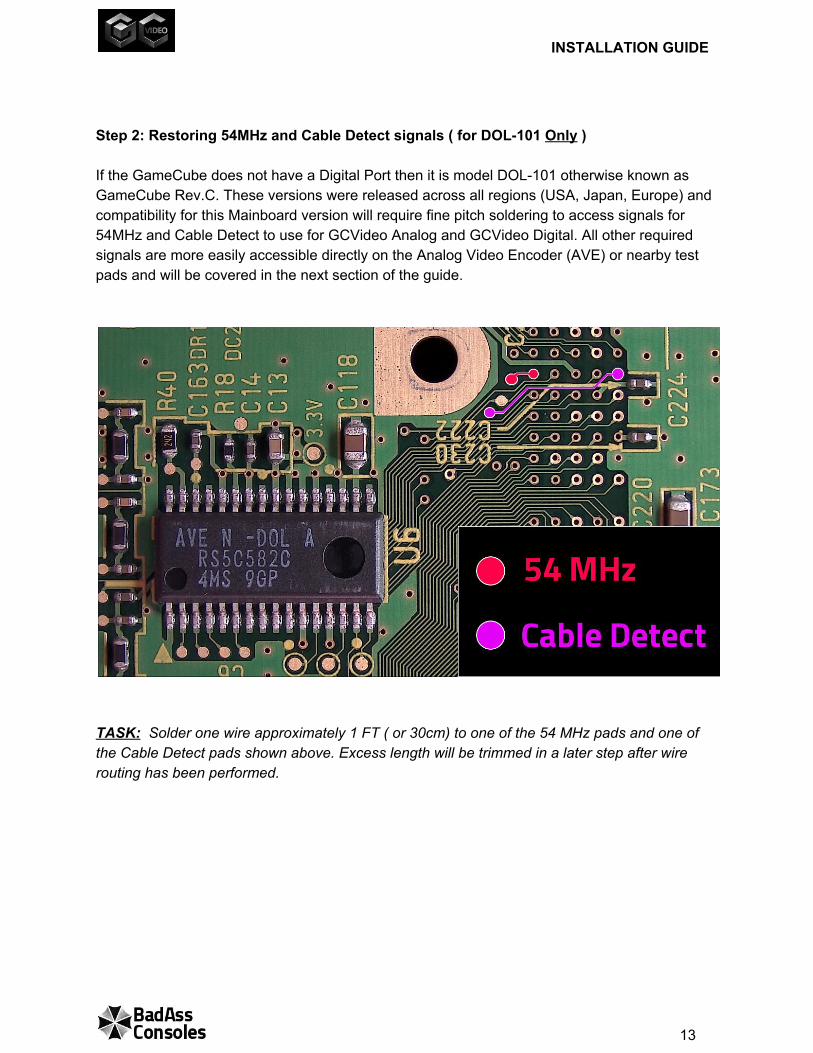
Step 2: Restoring 54MHz and Cable Detect signals ( for DOL101 Only ) If the GameCube does not have a Digital Port then it is model DOL101 otherwise known as GameCube Rev.C. These versions were released across all regions (USA, Japan, Europe) and compatibility for this Mainboard version will require fine pitch soldering to access signals for 54MHz and Cable Detect to use for GCVideo Analog and GCVideo Digital. All other required signals are more easily accessible directly on the Analog Video Encoder (AVE) or nearby test pads and will be covered in the next section of the guide.
TASK: Solder one wire approximately 1 FT ( or 30cm) to one of the 54 MHz pads and one of the Cable Detect pads shown above. Excess length will be trimmed in a later step after wire routing has been performed.
13
INSTALLATION GUIDE
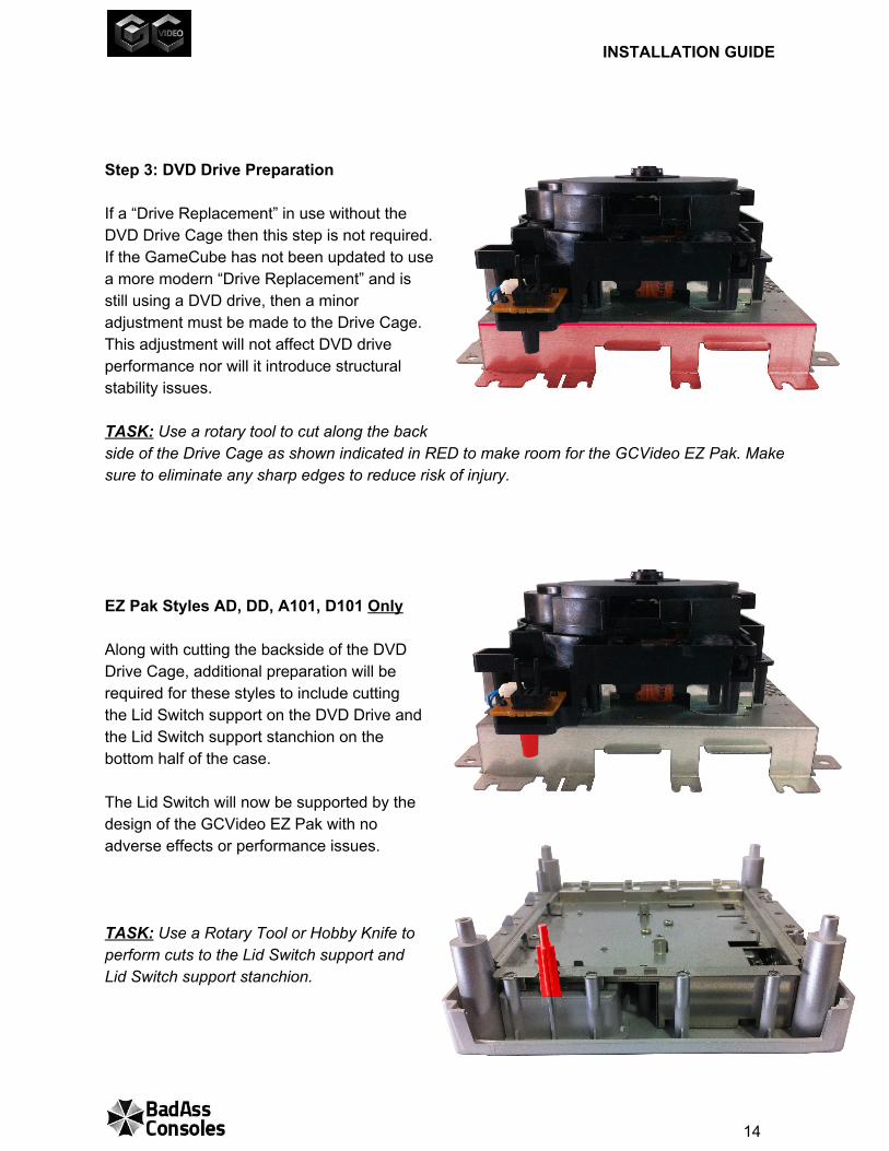
Step 3: DVD Drive Preparation If a “Drive Replacement” in use without the DVD Drive Cage then this step is not required. If the GameCube has not been updated to use a more modern “Drive Replacement” and is still using a DVD drive, then a minor adjustment must be made to the Drive Cage. This adjustment will not affect DVD drive performance nor will it introduce structural stability issues. TASK: Use a rotary tool to cut along the back side of the Drive Cage as shown indicated in RED to make room for the GCVideo EZ Pak. Make sure to eliminate any sharp edges to reduce risk of injury. EZ Pak Styles AD, DD, A101, D101 Only Along with cutting the backside of the DVD Drive Cage, additional preparation will be required for these styles to include cutting the Lid Switch support on the DVD Drive and the Lid Switch support stanchion on the bottom half of the case. The Lid Switch will now be supported by the design of the GCVideo EZ Pak with no adverse effects or performance issues. TASK: Use a Rotary Tool or Hobby Knife to perform cuts to the Lid Switch support and Lid Switch support stanchion.
14
INSTALLATION GUIDE
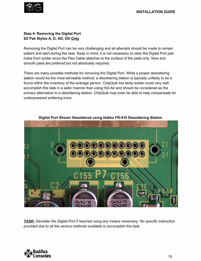
Step 4: Removing the Digital Port EZ Pak Styles A, D, AD, DD Only Removing the Digital Port can be very challenging and all attempts should be made to remain patient and alert during this task. Keep in mind, it is not necessary to clear the Digital Port pad holes from solder since the Flex Cable attaches to the surface of the pads only. Nice and smooth pads are prefered but not absolutely required. There are many possible methods for removing the Digital Port. While a proper desoldering station would be the most advisable method, a desoldering station is typically unlikely to be a found within the inventory of the average person. ChipQuik low temp solder could very well accomplish this task in a safer manner than using Hot Air and should be considered as the primary alternative to a desoldering station. ChipQuik may even be able to help compensate for underpowered soldering irons.
Digital Port Shown Desoldered using Hakko FR410 Desoldering Station
TASK: Desolder the Digital Port if required using any means necessary. No specific instruction provided due to all the various methods available to accomplish this task.
15
INSTALLATION GUIDE
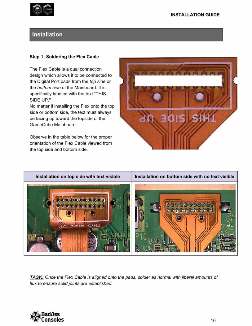
Installation Step 1: Soldering the Flex Cable The Flex Cable is a dual connection design which allows it to be connected to the Digital Port pads from the top side or the bottom side of the Mainboard. It is specifically labeled with the text “THIS SIDE UP.” No matter if installing the Flex onto the top side or bottom side, the text must always be facing up toward the topside of the GameCube Mainboard. Observe in the table below for the proper orientation of the Flex Cable viewed from the top side and bottom side.
Installation on top side with text visible Installation on bottom side with no text visible
TASK: Once the Flex Cable is aligned onto the pads, solder as normal with liberal amounts of flux to ensure solid joints are established.
16
INSTALLATION GUIDE
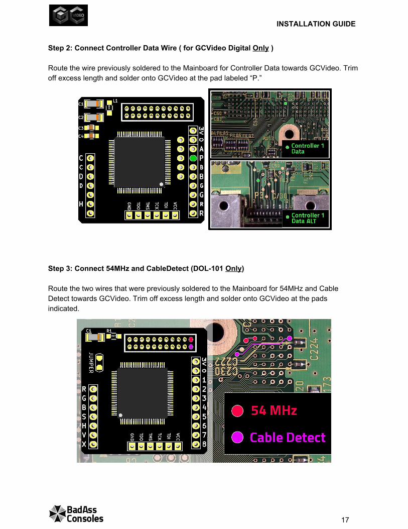
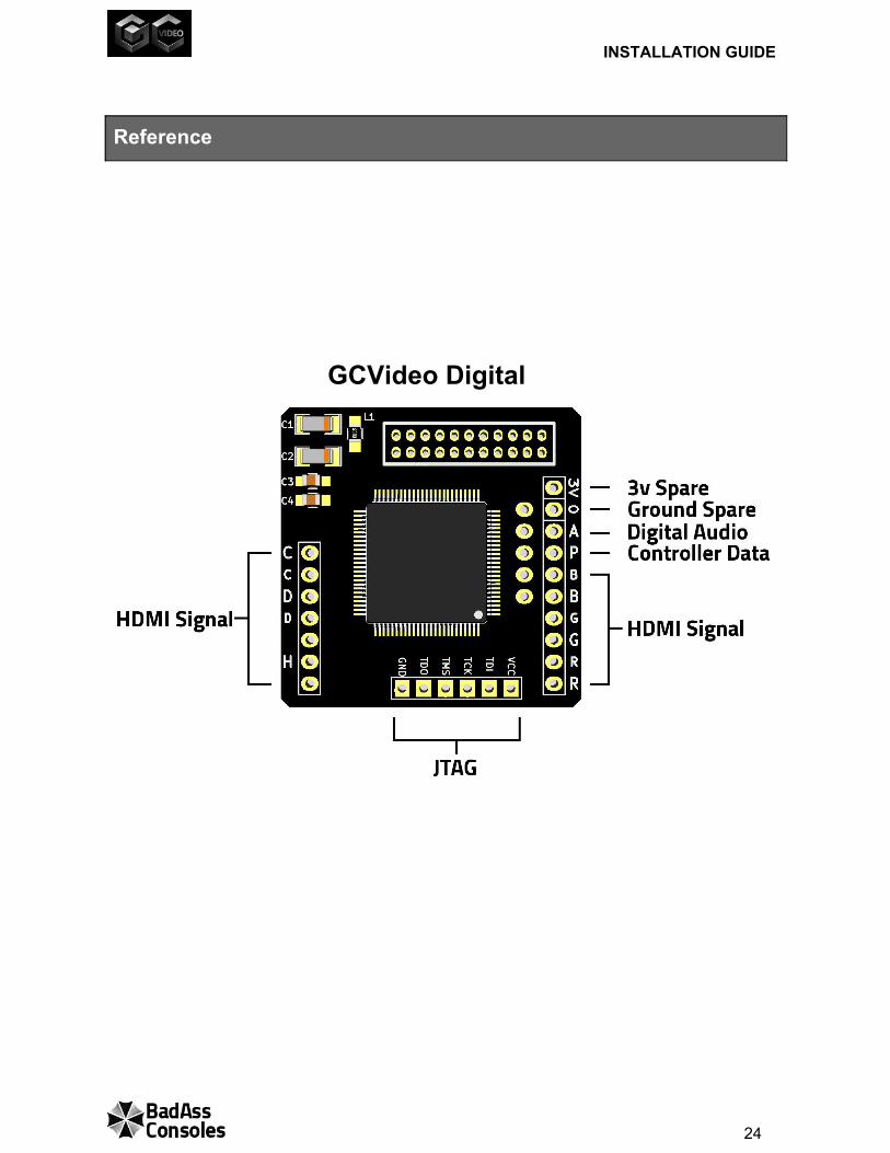
Step 2: Connect Controller Data Wire ( for GCVideo Digital Only ) Route the wire previously soldered to the Mainboard for Controller Data towards GCVideo. Trim off excess length and solder onto GCVideo at the pad labeled “P.” Step 3: Connect 54MHz and CableDetect (DOL101 Only) Route the two wires that were previously soldered to the Mainboard for 54MHz and Cable Detect towards GCVideo. Trim off excess length and solder onto GCVideo at the pads indicated.
17
INSTALLATION GUIDE
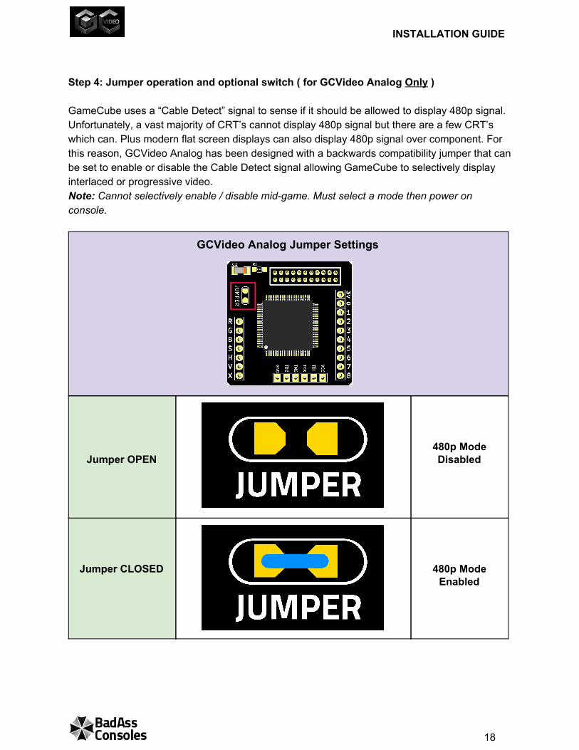
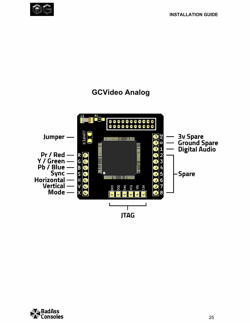
Step 4: Jumper operation and optional switch ( for GCVideo Analog Only ) GameCube uses a “Cable Detect” signal to sense if it should be allowed to display 480p signal. Unfortunately, a vast majority of CRT’s cannot display 480p signal but there are a few CRT’s which can. Plus modern flat screen displays can also display 480p signal over component. For this reason, GCVideo Analog has been designed with a backwards compatibility jumper that can be set to enable or disable the Cable Detect signal allowing GameCube to selectively display interlaced or progressive video. Note: Cannot selectively enable / disable midgame. Must select a mode then power on console.
GCVideo Analog Jumper Settings
Jumper OPEN
480p Mode Disabled
Jumper CLOSED
480p Mode Enabled
18
INSTALLATION GUIDE
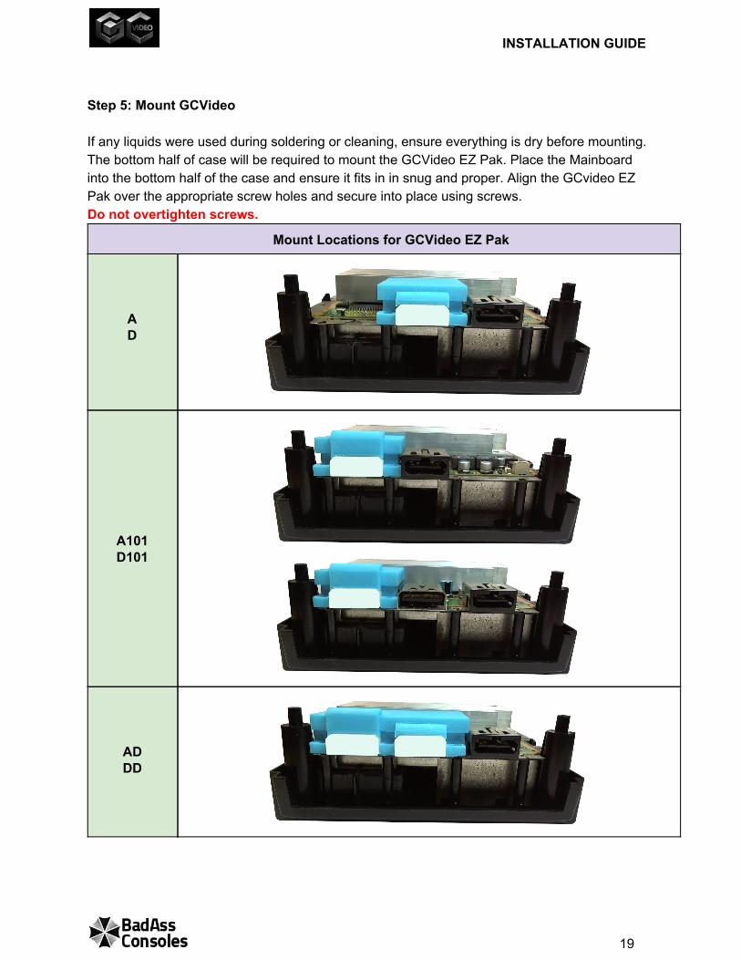
Step 5: Mount GCVideo If any liquids were used during soldering or cleaning, ensure everything is dry before mounting. The bottom half of case will be required to mount the GCVideo EZ Pak. Place the Mainboard into the bottom half of the case and ensure it fits in in snug and proper. Align the GCvideo EZ Pak over the appropriate screw holes and secure into place using screws. Do not overtighten screws.
Mount Locations for GCVideo EZ Pak
A D
A101 D101
AD DD
19
INSTALLATION GUIDE
TESTING
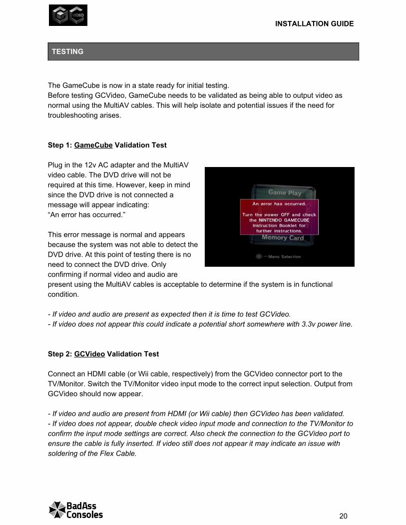
The GameCube is now in a state ready for initial testing. Before testing GCVideo, GameCube needs to be validated as being able to output video as normal using the MultiAV cables. This will help isolate and potential issues if the need for troubleshooting arises. Step 1: GameCube Validation Test Plug in the 12v AC adapter and the MultiAV video cable. The DVD drive will not be required at this time. However, keep in mind since the DVD drive is not connected a message will appear indicating: “An error has occurred.” This error message is normal and appears because the system was not able to detect the DVD drive. At this point of testing there is no need to connect the DVD drive. Only confirming if normal video and audio are present using the MultiAV cables is acceptable to determine if the system is in functional condition. If video and audio are present as expected then it is time to test GCVideo. If video does not appear this could indicate a potential short somewhere with 3.3v power line. Step 2: GCVideo Validation Test Connect an HDMI cable (or Wii cable, respectively) from the GCVideo connector port to the TV/Monitor. Switch the TV/Monitor video input mode to the correct input selection. Output from GCVideo should now appear. If video and audio are present from HDMI (or Wii cable) then GCVideo has been validated. If video does not appear, double check video input mode and connection to the TV/Monitor to confirm the input mode settings are correct. Also check the connection to the GCVideo port to ensure the cable is fully inserted. If video still does not appear it may indicate an issue with soldering of the Flex Cable.
20
INSTALLATION GUIDE
Step 3: For GCVideo Digital Only Ensure GameCube is powered off. Plug in the controller board and a control pad. Power on the console. Hold Ltrigger + Rtrigger + X button + Y button. The OSD menu should appear after holding the button combination for approximately 2 seconds. If the OSD menu appears then controller data connection has been verified and validated functional. If the OSD menu does not appear, double check the Controller Data wiring. EZ Pak DD ONLY: Primary HDMI output is located in the center of the rear panel. The secondary HDMI output is located on the left of the rear panel. Hold Ltrigger + Rtrigger + B button + Y button. The OSD Menu should appear on the secondary HDMI display Step 4: For GCVideo Analog Only ( for Progressive Mode Compatible TVs/ Monitors ) If GCVideo Analog is to be used with a Progressive Mode compatible display, then ensure GameCube is powered off and plug in the DVD Drive. Place a known 480p compatible DVD title in the drive. Power on and hold the B button until after the title boots and a message appears with the option to select progressive scan mode. Highlight and select progressive mode. The screen will go blank while GameCube adjusts to support the newly selected video output type. After the quick adjustment video will reappear in progressive mode. If the Progressive mode message appears and video switches over then test is complete and verified functional. If no message is displayed after holding the B button for a long length of time, try again. If the message still does not appear, this could indicate an issue with the Cable Detect signal. Double check the wiring and try again. Also ensure “JUMPER” has been set accordingly.
21
INSTALLATION GUIDE
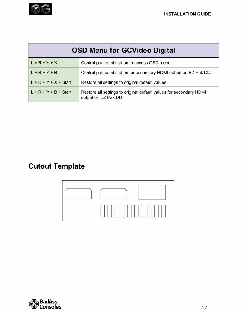
Reassembly Follow the instructions for Disassembly in reverse. EZ Pak Styles AD, DD, A101, D101 Only Position the Cutout template over the back panel and use a Hobby Knife to mark an outline of the area to cut. Use a Rotary Tool to carefully cut out a section within the outlined area. Ensure not to cut beyond the outlined area. Needle files can then be used to sand and shape the remaining portion to meet the marked lines providing a nice smooth finish to the cutout.
22
INSTALLATION GUIDE
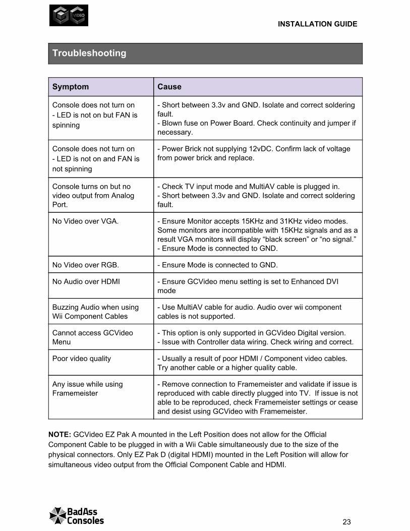
Troubleshooting
Symptom Cause
Console does not turn on LED is not on but FAN is spinning
Short between 3.3v and GND. Isolate and correct soldering fault. Blown fuse on Power Board. Check continuity and jumper if necessary.
Console does not turn on LED is not on and FAN is not spinning
Power Brick not supplying 12vDC. Confirm lack of voltage from power brick and replace.
Console turns on but no video output from Analog Port.
Check TV input mode and MultiAV cable is plugged in. Short between 3.3v and GND. Isolate and correct soldering fault.
No Video over VGA. Ensure Monitor accepts 15KHz and 31KHz video modes. Some monitors are incompatible with 15KHz signals and as a result VGA monitors will display “black screen” or “no signal.” Ensure Mode is connected to GND.
No Video over RGB. Ensure Mode is connected to GND.
No Audio over HDMI Ensure GCVideo menu setting is set to Enhanced DVI mode
Buzzing Audio when using Wii Component Cables
Use MultiAV cable for audio. Audio over wii component cables is not supported.
Cannot access GCVideo Menu
This option is only supported in GCVideo Digital version. Issue with Controller data wiring. Check wiring and correct.
Poor video quality Usually a result of poor HDMI / Component video cables. Try another cable or a higher quality cable.
Any issue while using Framemeister
Remove connection to Framemeister and validate if issue is reproduced with cable directly plugged into TV. If issue is not able to be reproduced, check Framemeister settings or cease and desist using GCVideo with Framemeister.
NOTE: GCVideo EZ Pak A mounted in the Left Position does not allow for the Official Component Cable to be plugged in with a Wii Cable simultaneously due to the size of the physical connectors. Only EZ Pak D (digital HDMI) mounted in the Left Position will allow for simultaneous video output from the Official Component Cable and HDMI.
23
INSTALLATION GUIDE
Reference
GCVideo Digital ..
24
INSTALLATION GUIDE
GCVideo Analog .
25
INSTALLATION GUIDE
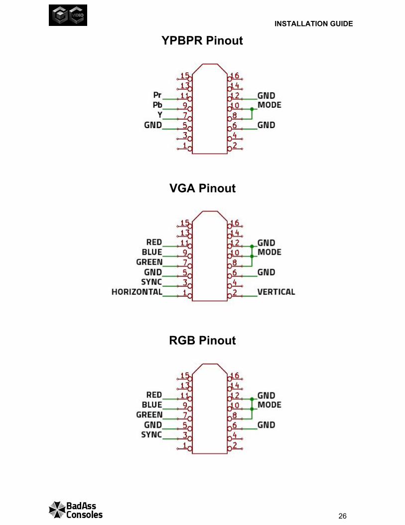
YPBPR Pinout
VGA Pinout
RGB Pinout
26
INSTALLATION GUIDE
OSD Menu for GCVideo Digital L + R + Y + X Control pad combination to access OSD menu.
L + R + Y + B Control pad combination for secondary HDMI output on EZ Pak DD.
L + R + Y + X + Start Restore all settings to original default values.
L + R + Y + B + Start Restore all settings to original default values for secondary HDMI output on EZ Pak DD.
Cutout Template
27


![The TAo of Badass Joshua Pellicer’s Life Story [Transcript]the-tao-of-badass.s3.amazonaws.com/interviews/badass-life-story.pdf · Copyright 2011 The TAo of Badass Joshua Pellicer’s](https://img.pdfslide.net/doc/110x75/5adf56137f8b9a6e5c8c091e/the-tao-of-badass-joshua-pellicers-life-story-transcriptthe-tao-of-badasss3.jpg)


![Badass Life Story[1]](https://img.pdfslide.net/doc/110x75/553451744a795994618b4a5f/badass-life-story1.jpg)


![Badass [portrait version]](https://img.pdfslide.net/doc/110x75/568cad9e1a28ab186dac6bbd/badass-portrait-version.jpg)