Embed Size (px)
Citation preview


Table of Contents
1 Introduction . . . . . . . . . . . . . . . 31.1 Technical Specifications . . . . . 41.2 Safety Instructions . . . . . . . . 5
2 Mounting Instructions . . . . . . . . . 6
3 Settings . . . . . . . . . . . . . . . . . 103.1 Temperature Settings . . . . . . 10
4 Warranty . . . . . . . . . . . . . . . . . 12
5 Disposal Instruction . . . . . . . . . . 12
1 Introduction
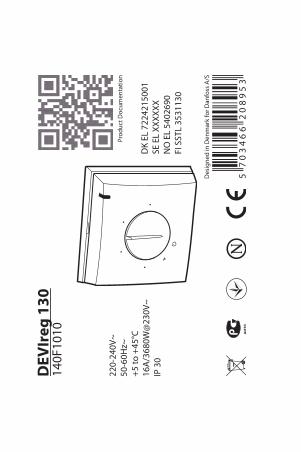
DEVIreg™ 130 is an electronic thermostat to be installed di-rectly on the wall. It is provided with a floor sensor to meas-ure and control the desired floor temperature.
The thermostat has a button for adjusting the temperaturesetting with a scale from ( ) 1 to 5 (each step correspondsto approximately 9°C). Furthermore, the thermostat has anLED indicator showing standby periods (green light) andheating periods (red light).
More information on this product can also be found at:devireg.devi.com
DEVIreg™ 130
Installation Guide 3

1.1 Technical Specifications
Operation voltage 220-240V~, 50Hz
Power consumption Max 5W
Relay:
Resistive load Max 16A / 3680W @ 230V
Inductive load cos φ= 0.3 max 1A
Sensing units NTC 15 kOhm at 25°C
Sensing values:
0°C 42 kOhm
25°C 15 kOhm
50°C 6 kOhm
Hysteresis ± 0.2°C
Ambient temperature 0 to +30°C
Frost protection temperature 5°C -
Temperature range ( ) 5-45°C
Cable specification max 1x4mm2 or 2x2,5mm2
Ball pressure temperature 75°C
Pollution degree Degree 2 (domestic use)
Type 1C
Storage temperature -20 to +65°C
DEVIreg™ 130
4 Installation Guide

IP class 30
Protection class Class II -
Dimensions 82 x 82 x 36mm
Weight 90g
The product complies with the EN/IEC Standard "Automaticelectrical controls for household and similar use":
▪ EN/IEC 60730-1 (general)▪ EN/IEC 60730-2-9 (thermostat)
1.2 Safety Instructions
Make sure the mains supply to the thermostat is turned offbefore installation.
IMPORTANT: When the thermostat is used to control afloor heating element in connection with a wooden floor orsimilar material, always use a floor sensor and never set themaximum floor temperature to more than 35°C.
Please also note the following:
▪ The installation of the thermostat must be done by anauthorized and qualified installer according to localregulations.
▪ The thermostat must be connected to a power supplyvia an all-pole disconnection switch.
DEVIreg™ 130
Installation Guide 5

▪ The sensor is to be considered as live voltage. Havethis in mind if the sensor must be extended.
▪ Always connect the thermostat to continuous powersupply.
▪ Do not expose the thermostat to moisture, water, dust,and excessive heat.
2 Mounting Instructions
Please observe the following placement guidelines:
Place the thermostat at a suitable height onthe wall (typically 80-170cm.).
In wet rooms, place the thermostat accordingto local regulation on IP classes.
Do not place the thermostat on the inner sideof an exterior wall.
DEVIreg™ 130
6 Installation Guide

▪ Place the floor sensor in a conduit in anappropriate place where it is not exposedto sunlight or draft from door openings.
▪ Equally distant and >2cm from two heat-ing cables.
▪ The conduit should be flush with the floorsurface - countersink the conduit if neces-sary.
▪ Route the conduit to the connection box.▪ The bending radius of the conduit must
be min 50mm.
DEVIreg™ 130
Installation Guide 7

Follow the steps below to mount the thermostat:
1. Open the thermostat:
▪ Lift off the button using a small screwdriver.▪ Loosen the screw which holds the front.▪ Push down the release tab at the top of the thermo-
stat using a flat object while slowly pulling off thefront cover.
DEVIreg™ 130
8 Installation Guide

2. Fasten the thermostat directly to the wall by drivingthe screws through the holes in each side of the ther-mostat.
= Screw holes for fastening the thermostat.
3. Connect the thermostat according to the connectiondiagram.
IP30
0T30
D130
NTCLN1 2 3 4
Se
nso
r
Max.Load
16 (1) A
Mains
220-240V~
NLOAD
LLOAD
The screen of the heating cable must be connected tothe earth conductor of the power supply cable by us-ing a separate connector.
Note: Always install the floor sensor in a conduit in thefloor.
DEVIreg™ 130
Installation Guide 9

4. Install the front cover and button in the reverse orderof disassembly.
5. Turn on the power supply.
3 Settings
3.1 Temperature Settings
How to change the minimum and maximum floor tem-peratures
1. Lift off the adjustmentbutton using a thinscrewdriver. (1)
2. Move the pins to thedesired positions. (2and 3)
3. Put the adjustmentbutton back in place.
Please be aware of the following:
▪ The floor temperature is measured where the sensor isplaced.
▪ The temperature of the bottom of a wooden floor canbe up to 10 degrees higher than the top.
DEVIreg™ 130
10 Installation Guide

▪ Floor manufactures often specify the max temperatureon the top surface of the floor (usually 27-28˚C).
▪ By default, the maximum floor temperature is set to35°C.
▪ Always use a floor sensor or a room + floor sensorcombination to control floor heating. Without a floorsensor, the temperature control may be less accurateand you risk overheating the floor.
Thermalresist-ance[m2K/W]
Examples of floor-ing
Details Approximatesetting for25˚C floortemperature
0.05 8 mm HDF basedlaminate
> 800 kg/m3 28˚C
0.10 14 mm beech par-quet
650 - 800kg/m3
31˚C
0.13 22 mm solid oakplank
> 800 kg/m3 32˚C
< 0.17 Max. carpet thick-ness suitable forfloor heating
acc. to EN1307
34˚C
0.18 22 mm solid firplanks
450 - 650kg/m3
35°C
DEVIreg™ 130
Installation Guide 11

4 Warranty
2Y E A R
5 Disposal Instruction
DEVIreg™ 130
12 Installation Guide

DEVIreg™ 130
Installation Guide 13

DEVIreg™ 130
14 Installation Guide

DEVIreg™ 130
Danfoss A/SElectric Heating SystemsUlvehavevej 617100 VejleDenmarkPhone: +45 7488 8500Fax: +45 7488 8501E-mail: [email protected]
Danfoss can accept no responsibility for possible errors in catalogues, brochures and other printed material. Danfoss reserves the right to alter itsproducts without notice. This also applies to products already on order provided that such alterations can be made without subsequential changesbeing necessary in specifications already agreed. All trademarks in this material are property of the respective companies. DEVI and the DEVI logo-type are trademarks of Danfoss A/S. All rights reserved.
08095775 & VICKD202 Produced by Danfoss © 06/2012
DEV
Ireg
130
140F
1010
220-
240V
~50
-60H
z~+5
to +
45°C
16A
/368
0W@
230V
~IP
30
Prod
uct D
ocum
enta
tion
DK
EL 7
2242
1500
1SE
EL
XXXX
XXN
O E
L 54
0269
0FI
SST
L 35
3113
0
Des
igne
d in
Den
mar
k fo
r Dan
foss
A/S
5703466
208953
![Rotary Position Sensor Line Guide...Terminal type turret turret three 20 AWG, 152,4 mm [6.0 in] leads Resistance range 500 Ohm to 20 kOhm 1 kOhm to 10 kOhm 10000 ohms (total resistance)](https://img.pdfslide.net/doc/110x75/609328ecdc62306f8e23a03c/rotary-position-sensor-line-guide-terminal-type-turret-turret-three-20-awg.jpg)


![Rotary Position Sensor Line Guide - Steven Engineering...Terminal type turret turret three 20 AWG, 152,4 mm [6.0 in] leads Resistance range 500 Ohm to 20 kOhm 1 kOhm to 10 kOhm 10000](https://img.pdfslide.net/doc/110x75/609328ecdc62306f8e23a03d/rotary-position-sensor-line-guide-steven-engineering-terminal-type-turret.jpg)