Embed Size (px)
Citation preview
CoBox
Network Time Server
Installation Guide
CONTENTS
1 DESCRIPTION OF THE NETWORK TIME SERVER (NTS)
2 RELIABLE CLOCK SOURCES
GLOBAL POSITIONING SATELLITE (GPS) SYSTEM .................................. 2-1DCF-77 LF RADIO TRANSMITTER......................................................... 2-1WWVB RADIO TRANSMITTER .............................................................. 2-1
3 HARDWARE INSTALLATION REQUIREMENTS
CONTROLLER........................................................................................ 3-1ANTENNA ............................................................................................. 3-1ANTENNA CABLE.................................................................................. 3-1
4 CONTROLLER SETUP
NETWORK CONFIGURATION .................................................................. 4-1FACTORY IP ADDRESS .......................................................................... 4-1INITIAL IP ADDRESS SETTING ............................................................... 4-1SERIAL CONFIGURATION ....................................................................... 4-2CONFIGURATION PARAMETERS ............................................................. 4-3BASIC PARAMETERS ............................................................................. 4-3
Ethernet Interface ......................................................................... 4-3Token Ring Interface .................................................................... 4-3Locally Administered Hardware Address ...................................... 4-3IP Address.................................................................................... 4-3Gateway IP Address ..................................................................... 4-3Netmask....................................................................................... 4-4Telnet Config Password................................................................ 4-4
5 NETWORK CLOCK PARAMETERS
ANTENNA TYPE .................................................................................... 5-1UDP-PORT ........................................................................................... 5-1SEND BLOCK EVERY N MINUTES ........................................................... 5-1SEND UDP-BROADCAST ....................................................................... 5-1UDP-TARGET ADDRESS........................................................................ 5-1
6 TIME DISTRIBUTION FORMATS
NTP..................................................................................................... 6-1UDP/TIME ............................................................................................ 6-1LANTRONIX PROPRIETARY .................................................................... 6-1
7 NETWORK CONNECTORS
8 SERIAL AND ANTENNA INTERFACE
9 ANTENNA
GPS RECEIVER ..................................................................................... 9-1DCF-77 ANTENNA ............................................................................... 9-1
Input pulse of the DCF-77 source.................................................. 9-1Antennas with positive pulse output.............................................. 9-2Antennas with negative pulse output ............................................. 9-2Antennas with open collector outputs............................................ 9-3
10 LED STATUS AND ERROR CODES
GREEN LED ON .................................................................................. 10-1GREEN LED FLASHING 50% DUTY CYCLE............................................ 10-1
FOR CONNECTED DCF-77 ONLY………………………………………..10-1RED LED ........................................................................................... 10-1
Red LED stable on, green LED blinking ..................................... 10-1Red LED blinking, green LED blinking ...................................... 10-1
11 MONITOR MODE AND FIRMWARE UPLOAD
MONITOR MODE ................................................................................. 11-1MONITOR COMMANDS ........................................................................ 11-1
Command Result Codes.............................................................. 11-1FIRMWARE DOWNLOAD SERIAL .......................................................... 11-2DISTRIBUTE FIRMWARE ...................................................................... 11-3FIRMWARE DOWNLOAD FROM HOST.................................................... 11-3
12 TECHNICAL DATA
CPU, MEMORY, CONTROLLERS .......................................................... 12-1SERIAL INTERFACE ............................................................................. 12-1NETWORK INTERFACE......................................................................... 12-1POWER SUPPLY................................................................................... 12-1POWER CONSUMPTION ........................................................................ 12-1LEDS ................................................................................................. 12-1CASE.................................................................................................. 12-1DIMENSIONS ....................................................................................... 12-1WEIGHT ............................................................................................. 12-1
APPENDIX AAPPENDIX BAPPENDIX C
WARRANTY AND DECLARATIONS
Description of NTS
1-1
1 Description of the Network Time Server (NTS)The Network Time Server (NTS) is a compact, standalone unit whichreceives standard world time information from a reliable source (GPS orDCF-77) and makes this information available to computers, controllers andother equipment needing the correct time. This data is distributed over thenetwork interface. The NTS supports the most popular time distributionprotocols, NTP, time/UDP, plus an easy-to-integrate proprietary protocolthat supports broadcasting.
The NTS controller needs an external GPS or DCF-77 receiver, which canbe connected via a serial link and mounted away from the unit.
NOTE: Network Time Server will be abbreviated as NTS in thismanual.
Reliable Clock Sources
2-1
2 Reliable Clock SourcesDepending on where the NTS will be used, the following clock sources areavailable:
2.1 Global Positioning Satellite (GPS) SystemGPS is a satellite system operated by the US Department of Defense that isused as a position determination aid. GPS can also be used to provideworld-wide coverage for accurate standard time information. A GPSantenna is typically mounted with free “view” of the sky.
2.2 DCF-77 LF Radio TransmitterA DCF-77 low frequency transmitter is located near Frankfurt, Germany.This transmitter is operated by the Physikalisch-Technische Bundesanstaltin Braunschweig. It modulates the German standard time on its carrier(77.5 kHz).
DCF-77 receivers work normally within about 1500 km radius aroundFrankfurt, but reception can be disturbed by mountains, buildings, railroads,power stations etc. Accurate positioning of a DCF-77 is often necessary toachieve reliable reception conditions.
2.3 WWVB Radio TransmitterWWVB radio transmitter is a low frequency transmitter located inBoulder, Colorado, USA at the NIST Boulder Laboratories. NIST maintainsthe primary frequency standard and also develops and operates standards oftime and frequency for the United States.
Hardware Installation Requirements
3-1
3 Hardware Installation Requirements
3.1 ControllerThe controller can be installed anywhere in the network and must beconnected through the appropriate interface and cables.
The external Ethernet and Token Ring models come with a power supply.The OEM board and the 19-inch rack mount versions need a regulated DCpower supply.
3.2 AntennaThe GPS antenna works best when mounted with a free view of the sky.The DCF-77 antenna should be as far away as possible from monitors,power lines and other low-frequency radiation sources. The DCF antennainstallation must be carefully done to avoid reception problems.
NOTE: In most cases, reception behind shielded windows or incomputer rooms is not possible.
3.3 Antenna CableDepending on the antenna type, the cable can be up to 150 feet in length.LED status indicators on the controller can help finding the best installationplace (see “LED status and error codes,” page 10-1).
Controller Setup
4-1
4 Controller (NTS) SetupThe controller must be configured before initial LAN installation.Configuration should be made through its serial port and terminal (orterminal emulation software) on a PC. The NTS can be configured locallyor remotely. To configure locally, access the first (or only) serial port by anASCII terminal or terminal emulation; configuring over the network uses aPC or other computer with a Telnet client.
The NTS configuration is stored in nonvolatile memory (with option 9) andis retained without a power supply. The configuration can be changed at anytime. The NTS resets after the configuration has been modified and stored.
4.1 Network ConfigurationTo configure over the network, a Telnet connection to port 9999 must beestablished.
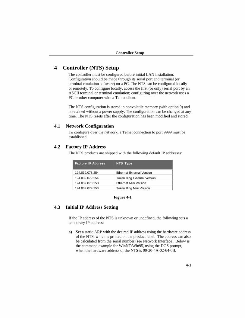
4.2 Factory IP AddressThe NTS products are shipped with the following default IP addresses:
Factory IP Address NTS Type
194.039.078.254 Ethernet External Version
194.039.079.254 Token Ring External Version
194.039.078.253 Ethernet Mini Version
194.039.079.253 Token Ring Mini Version
Figure 4-1
4.3 Initial IP Address Setting
If the IP address of the NTS is unknown or undefined, the following sets atemporary IP address:
a) Set a static ARP with the desired IP address using the hardware addressof the NTS, which is printed on the product label. The address can alsobe calculated from the serial number (see Network Interface). Below isthe command example for WinNT/Win95, using the DOS prompt,when the hardware address of the NTS is 00-20-4A-02-64-0B.
Controller Setup
4-2
NOTE: In order for the ARP command to work in Windows, the ARP tableon the PC must have at least one IP address defined other than itsown. Type “ARP –A” at the DOS command prompt to verify thatthere is at least one entry in the ARP table. If there is no otherentry beside the local machine, ping another IP machine on yournetwork to build the ARP table. This has to be a host other than themachine that you're working on. Once there is at least one entry inthe ARP table, use the following commands to ARP an IP addressto the NTS.
arp -s 191.12.3.77 00-20-4A-02-64-0B
The command example for most Unix systems is:
arp -s 191.12.3.77 00:20:4A:02:64:0B
b) Open a telnet connection to port number 1. This connection will fail, butthe NTS will change its IP address to the desired one in that step.
telnet 191.12.3.77 1
c) Open a telnet connection to port 9999 and set all required parameters.
telnet 191.12.3.77 9999
NOTE: The temporary IP address is reverted after every power reset of theNTS. Be sure to enter the configuration and store the parametersto make the changes permanent.
4.4 Serial ConfigurationAn ASCII terminal or PC with a terminal emulation can be connected to thefirst serial port of the NTS. The terminal (or PC) should be configured to9600 Baud, no parity, 8-bit, 1- or 2-stop bits.
The power must be cycled on the NTS (powered off and back on) to enterits configuration mode. The self-test begins after power-up. About a half-second later the red LED start blinking. Now send three lowercase ‘x’characters to the NTS. These characters must all be sent within one secondto start configuration mode.
Controller Setup
4-3
NOTE: The easiest way to enter configuration mode is to hold down the ‘x’key at the terminal(emulation) and then powering the NTS. Thiswill ensure that the x characters will arrive in time
4.5 Configuration ParametersAfter configuration mode is entered (confirm with <CR>), the parameterscan be changed; default values can be confirmed with the enter key. Theparameters must be stored, and the CoBox does a reset.
4.6 Basic ParametersTo change the basic parameters, type ‘0’. The following values can beset/changed:
4.6.1 Ethernet InterfaceThis parameter is used to select the network port on the External EthernetModel (10BaseT or AUI).
4.6.2 Token Ring InterfaceThe Token Ring network interface speed is set by a switch and cannot beset with software (see “Network Interface,” Appendix A).
4.6.3 Locally Administered Hardware AddressThe Token Ring locally administered hardware address can be set here.This parameter should not be changed without consulting the systemadministrator of your Token Ring LAN.
4.6.4 IP AddressThe IP address must be set to a unique value in your network. Please referto the literature mentioned in “Appendix C - IP Addresses, Netmask, etc.” ifyou are not familiar with IP addresses.
If the NTP is set to an address which is already in use, it will display anerror code with the LEDs (see “LED Status and Error Codes”) and will notconnect to the network.
4.6.5 Gateway IP AddressThe router/gateway address is needed to communicate to other LANsegments. The default gateway must be set to address the router thatconnects these segments. This address must be within the local network. Ifin doubt, consult the network administrator.
Controller Setup
4-4
4.6.6 NetmaskA netmask defines how many bits from the IP address are to be taken as thenetwork section and how many bits are to be taken as the host section(reminder: Standard class A 8/24 (net/host), class B 16/16, class C 24/8bits). If set to 0, the standard appropriate netmask for the actual IP addressis used. Appendix B covers the calculation of the right value in detail.
The NTS prompts for the number of host bits, and then calculates thenetmask. It is shown in standard format “255.255.xxx.xxx” whenparameters are displayed.
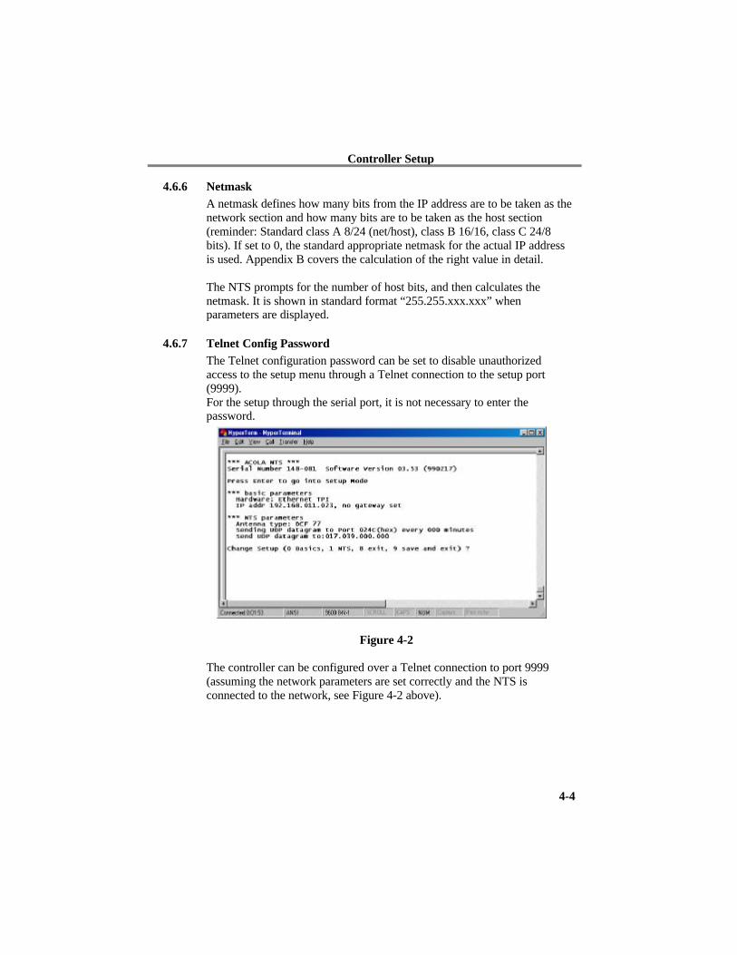
4.6.7 Telnet Config PasswordThe Telnet configuration password can be set to disable unauthorizedaccess to the setup menu through a Telnet connection to the setup port(9999).For the setup through the serial port, it is not necessary to enter thepassword.
Figure 4-2
The controller can be configured over a Telnet connection to port 9999(assuming the network parameters are set correctly and the NTS isconnected to the network, see Figure 4-2 above).
Network Clock Parameters
5-1
5 Network Clock ParametersThe network operations of the server are controlled by various parameters.
5.1 Antenna TypeAntenna Type (0=DCF77, 1=Trimble, 2=TRAK, 3=Hopf 6021)
The antenna type offers DCF-77, GPS (Trimble, TRAK, Hopf 6021),NMEA (DeLorme Tripmate, not supported at the time of printing thisdocument)
5.2 UDP-PortThe UDP port selects the port number for the NTP proprietary protocol. Itshould be set to 77FF (hexadecimal) to be compatible with PC software andKABA Benzing Terminals,
5.3 Send Block Every n MinutesThis parameter determines how often the data block should be sent.
5.4 Send UDP-BroadcastIf the time information should be sent to all devices connected to this LAN(broadcast), set this parameter to “Y” = yes.
5.5 UDP-Target AddressThis parameter determines the target addresses to which the data blockshould be sent. The data block can be sent over a Gateway or other devicesto another part of the network. The maximum number of defined addressesis eight.NTP and UDP/time port numbers are fixed to the values defined in RFC-37and RFC-123 respectively.
If the authentication option is enabled, up to seven MD5 or DES keys canbe entered (key numbers 1..7). All key input must be done in hexadecimalformat; MD5 key length is limited to eight characters.
When leaving the setup mode – after selecting function 9 – all parametersare stored in a nonvolatile memory and the NTS resets.
Time Distribution Formats
6-1
6 Time Distribution FormatsAfter the NTP receives valid time information, it distributes the standardtime via different services to systems connected to the LAN.
6.1 NTPThe NTS operates as in server mode—symmetric operation modes are notsupported. It understands NTP Version 1, 2 and 3 frames, and optionallysupports authentication via DES and MD5 cryptographic checksums. Ifauthentication is not used, the NTS can be used for hundreds of clientswithout overloading it.
Authentication requires 40ms for checking and generating the cryptograms,which is covered and averaged out by the protocol. The NTS supports fullSNTP and all NTP functions required for reliable server operation.Functions not required for server operation are not implemented.
6.2 UDP/timeThis outdated protocol has a resolution of one second, and is used by olderUNIX systems, some PCs and technical equipment.
6.3 Lantronix ProprietaryThis has been developed to ease the setting of KABA Benzing Terminalsand Network Time Servers that are connected to networks with BETA andBETOR network adapters. Also suitable for Windows 3.1, 3.11 PCs andother systems which do not support NTP. A simple C-program samplesource (available from our website) works on UNIX and VMS systems andcan easily be ported to others.
In central Europe, it can be used to facilitate automatic daylight savingsswitching, as the NTS knows the CET rule (and DCF-77 provides anindicator).
This protocol simply sends out a UDP block in a programmable interval asbroadcast or direct to targets. The port number can be set, but it is necessaryto set it to 77FF(hex) for operation with KABA Benzing equipment and theprovided software.
Time Distribution Formats
6-2
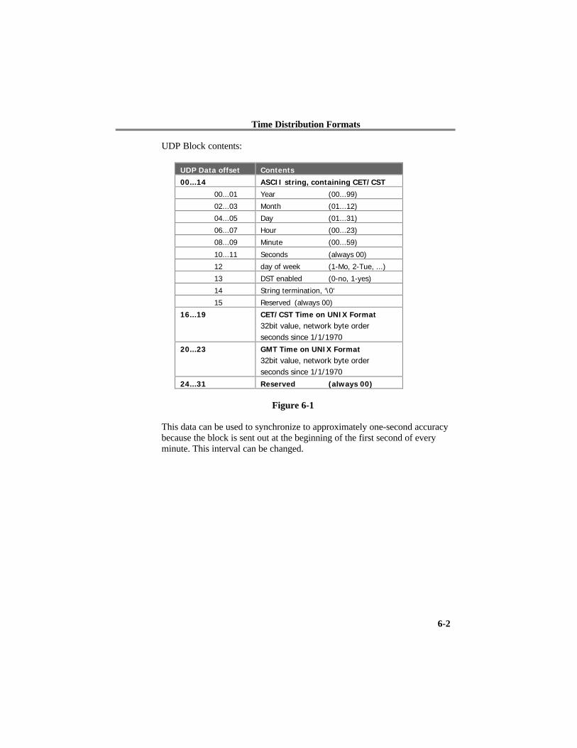
UDP Block contents:
UDP Data offset Contents
00...14 ASCII string, containing CET/CST
00...01 Year (00...99)
02...03 Month (01...12)
04...05 Day (01...31)
06...07 Hour (00...23)
08...09 Minute (00...59)
10...11 Seconds (always 00)
12 day of week (1-Mo, 2-Tue, ...)
13 DST enabled (0-no, 1-yes)
14 String termination, ‘\0‘
15 Reserved (always 00)
16...19 CET/CST Time on UNIX Format
32bit value, network byte orderseconds since 1/1/1970
20...23 GMT Time on UNIX Format
32bit value, network byte orderseconds since 1/1/1970
24...31 Reserved (always 00)
Figure 6-1
This data can be used to synchronize to approximately one-second accuracybecause the block is sent out at the beginning of the first second of everyminute. This interval can be changed.
Network Connectors
7-1
7 Network ConnectorsThe NTS features 10BaseT and AUI connectors. Active connectionselection is performed by software.
The transceiver interface can supply 12V, up to 300 mA. If more power isneeded (i.e. for a fiberoptic transceiver), an external transceiver powersupply must be used.
Serial and Antenna Interface
8-1
8 Serial and Antenna InterfaceThe setup menu and potential antenna connection is available only on thefirst serial port of the (NTS DB5 connector.)
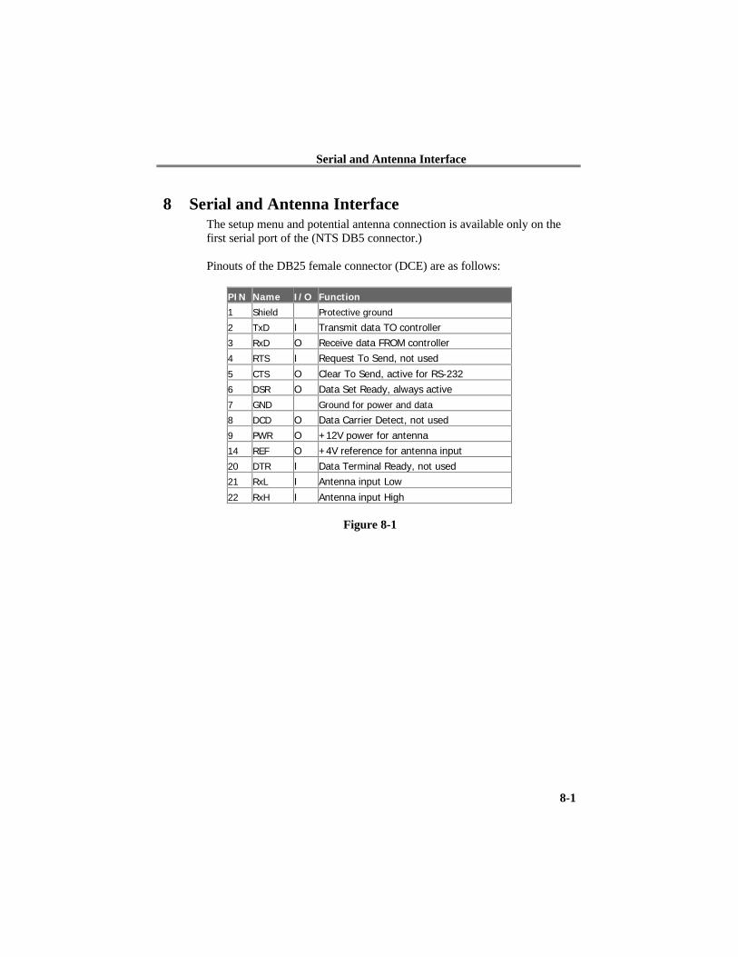
Pinouts of the DB25 female connector (DCE) are as follows:
PIN Name I/O Function
1 Shield Protective ground
2 TxD I Transmit data TO controller3 RxD O Receive data FROM controller4 RTS I Request To Send, not used
5 CTS O Clear To Send, active for RS-2326 DSR O Data Set Ready, always active7 GND Ground for power and data
8 DCD O Data Carrier Detect, not used9 PWR O +12V power for antenna14 REF O +4V reference for antenna input20 DTR I Data Terminal Ready, not used21 RxL I Antenna input Low
22 RxH I Antenna input High
Figure 8-1
Antenna
9-1
9 Antenna
9.1 GPS ReceiverGPS receivers are usually connected through a standard RS-232 interface; a1pps signal is also used. Most models of the NTS feature a DB25 connectorfor the serial interface (female, DCE pinning). The 19’’ rack version uses aRJ-45 connector, while the OEM module has a TTL level interface. +12Vregulated power for the receiver (max. 200mA) is available at the DB25connector only.
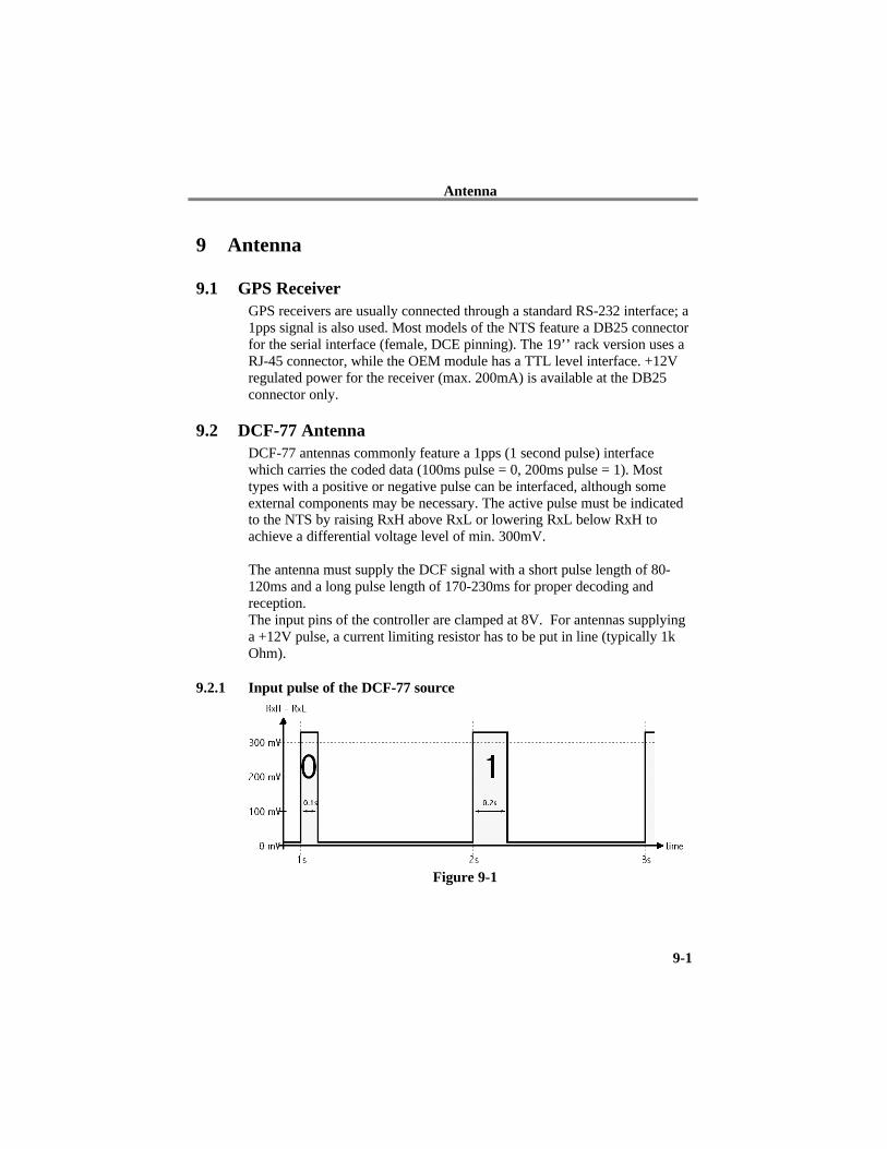
9.2 DCF-77 AntennaDCF-77 antennas commonly feature a 1pps (1 second pulse) interfacewhich carries the coded data (100ms pulse = 0, 200ms pulse = 1). Mosttypes with a positive or negative pulse can be interfaced, although someexternal components may be necessary. The active pulse must be indicatedto the NTS by raising RxH above RxL or lowering RxL below RxH toachieve a differential voltage level of min. 300mV.
The antenna must supply the DCF signal with a short pulse length of 80-120ms and a long pulse length of 170-230ms for proper decoding andreception.The input pins of the controller are clamped at 8V. For antennas supplyinga +12V pulse, a current limiting resistor has to be put in line (typically 1kOhm).
9.2.1 Input pulse of the DCF-77 source
Figure 9-1
Antenna
9-2
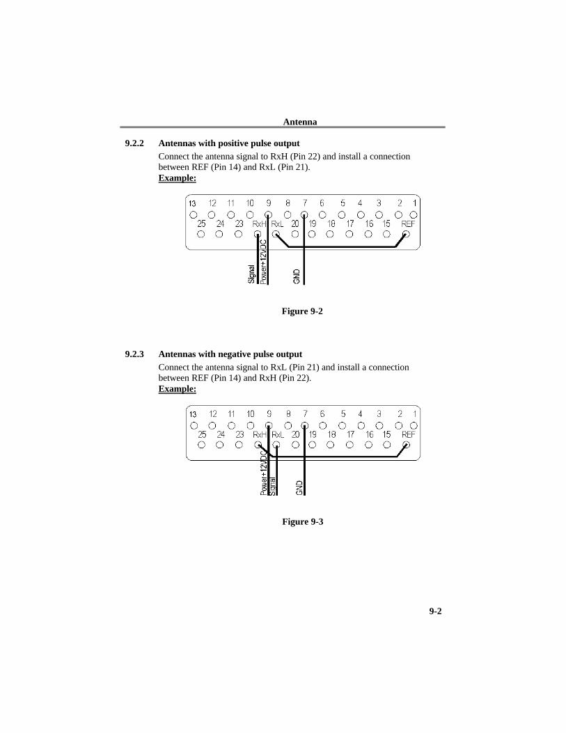
9.2.2 Antennas with positive pulse outputConnect the antenna signal to RxH (Pin 22) and install a connectionbetween REF (Pin 14) and RxL (Pin 21).Example:
Figure 9-2
9.2.3 Antennas with negative pulse outputConnect the antenna signal to RxL (Pin 21) and install a connectionbetween REF (Pin 14) and RxH (Pin 22).Example:
Figure 9-3
Antenna
9-3
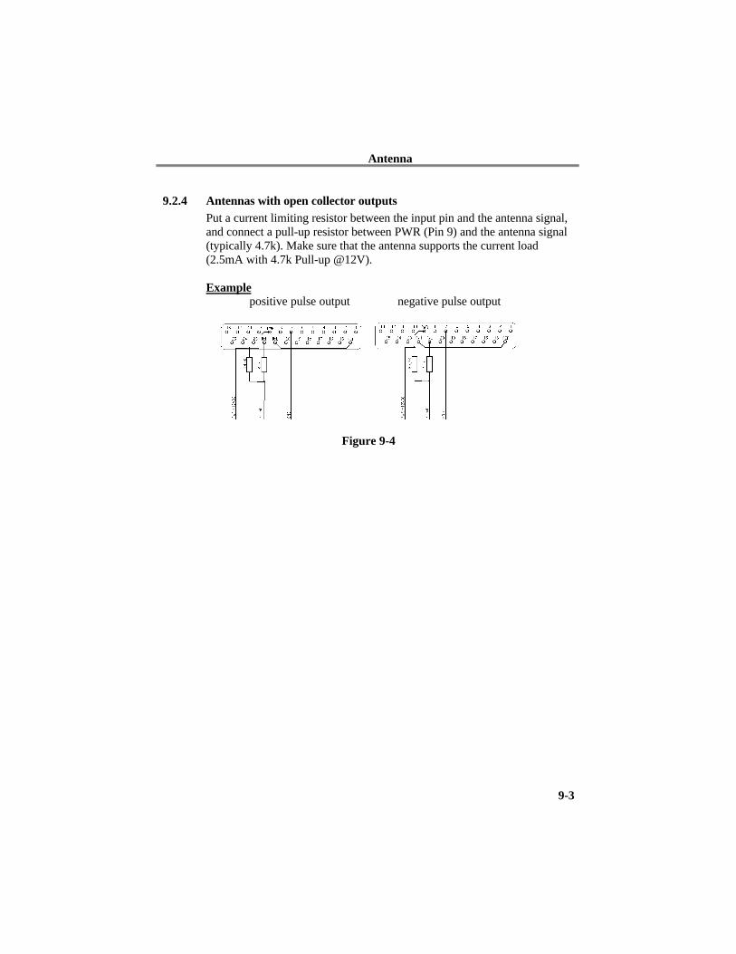
9.2.4 Antennas with open collector outputsPut a current limiting resistor between the input pin and the antenna signal,and connect a pull-up resistor between PWR (Pin 9) and the antenna signal(typically 4.7k). Make sure that the antenna supports the current load(2.5mA with 4.7k Pull-up @12V).
Examplepositive pulse output negative pulse output
Figure 9-4
LED Status and Error Codes
10-1
10 LED Status and Error CodesThe LEDs indicate the status of the NTS. After the initial self-test phase allstatus LEDs should be lit.
10.1 Green LED onSynchronized to the time signal, correct reception of time data.
10.2 Green LED flashing 50% duty cycleSome correct information received, but synchronization is not yet reliable.With the DCF-77 antenna, the controller demands three minutes of correctreception before becoming a synchronization source. Every receptiondropout restarts this phase for security reasons. GPS can take up to twentyminutes until correct synchronization is established (depending on theantenna position, type and other parameters).
10.3 For connected DCF-77 onlyThe yellow LED shows the pulse signal from the antenna, while shortflashes of the red LED indicate timing errors (or second 59).
10.4 Red LEDIf the red LED is on or blinking, the green LED will give a diagnostics code.There is a fatal error, and the NTS is not working.
10.4.1 Red LED stable on, green LED blinking:
1x: EPROM-checksum error2x: RAM-error3x Network controller error (Token Ring)4x: E²PROM checksum error or bad5x: IP address already used on network
10.4.2 Red LED blinking, green LED blinking:
4x: The network connection is faulty. This code should onlyappear after power up. Even though the NTS is going intooperation mode, the problem will potentially persist.
5x: No DHCP response was received.
Monitor Mode and Firmware Upgrade
11-1
11 Monitor Mode and Firmware Upgrade
11.1 Monitor ModeTo enter monitor mode, use the same steps as setting parameters (see SerialConfiguration). However, instead of entering three “x” keys, key in “x x1”. The NTS will respond with a special prompt.
Network functions are needed for some diagnostics commands; it may takeup to 20 seconds until the network part of the NTS is initialized and theprompt is displayed. This is especially true if a TokenRing is empty or aring simulator is used. For a simple ring simulator, see the Appendix. Tostart the monitor mode without network functions, enter “x x 2” (newfunction from Version 2.05 up).
NOTE: A Token Ring NTS needs a working network connection to entermonitor mode.
11.2 Monitor CommandsThe following commands are available in monitor mode. Many commandshave an IP address as an optional parameter (x.x.x.x). If it is given, thecommand is applied to a remote controller with that IP address (x.x.x.x). Ifno IP address is given, the command is executed locally.
All commands must be given in capital letters; only blanks are accepted aswhite space between parameters
DL Firmware download to the NTSSF x.x.x.x Send firmware to NTS with IP x.x.x.xVS x.x.x.x Query software header record (16-byte).GC x.x.x.x Get configuration as HEX recordsSC x.x.x.x Set configuration from HEX recordsPI x.x.x.x Check with ping if x.x.x.x is alive and reachable.QU Quit—exit diagnostics mode
11.2.1 Command Result Codes0 OK, no error1 No answer from remote device2 Cannot reach remote device or does not answer8 Wrong parameter(s)9 Invalid Command
Monitor Mode and Firmware Upgrade
11-2
11.3 Firmware Download SerialDownloading is done in monitor mode. Once in monitor mode, send the“DL” command. The NTS now waits for the firmware image in HEXformat, which must be sent as an ASCII-file through the serial interface.When the end record is received, the controller checks the integrity of thefirmware image and then programs the new firmware in the Flash prom.The NTS resets after complete reprogramming,.
WARNING: A loss of power while reprogramming will result in a defectprogram image and a nonfunctional NTS.

Monitor Mode and Firmware Upgrade
11-3
The following figure shows a typical screen shot during reprogramming ofthe downloaded firmware.
Figure 11-1
11.4 Distribute FirmwareTo distribute the firmware from one NTS to others, use the “SF” command.After entering monitor mode on the NTS, simply send the firmware with the“SF” command to the other devices. Be sure to check the version of theother devices after reprogramming to make sure the reprogramming was asuccess.
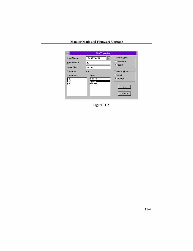
11.5 Firmware Download from HostTo download new firmware from a computer to a NTS, you much have asend a binary file from a TFTP client. The parameters to send the firmwareare:
Target filename: 3QTransfer mode: binary123
NOTE: The file to be downloaded must be the .ROM (binary) image, notthe hex version! File size should be 32768 or 65536 bytes.
Monitor Mode and Firmware Upgrade
11-4
Figure 11-2
Monitor Mode and Firmware Upgrade
11-5
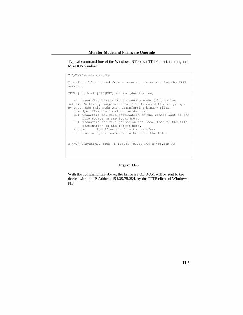
Typical command line of the Windows NT’s own TFTP client, running in aMS-DOS window:
C:\WINNT\system32>tftp
Transfers files to and from a remote computer running the TFTPservice.
TFTP [-i] host [GET|PUT] source [destination]
-i Specifies binary image transfer mode (also calledoctet). In binary image mode the file is moved literally, byteby byte. Use this mode when transferring binary files. host Specifies the local or remote host. GET Transfers the file destination on the remote host to the
file source on the local host. PUT Transfers the file source on the local host to the file
destination on the remote host. source Specifies the file to transfers destination Specifies where to transfer the file.
C:\WINNT\system32\tftp –i 194.39.78.254 PUT c:\qe.rom 3Q
Figure 11-3
With the command line above, the firmware QE.ROM will be sent to thedevice with the IP-Address 194.39.78.254, by the TFTP client of WindowsNT.
Technical Data
12-1
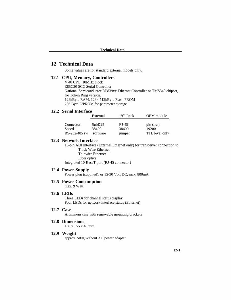
12 Technical DataSome values are for standard external models only.
12.1 CPU, Memory, ControllersV.40 CPU, 10MHz clockZ85C30 SCC Serial ControllerNational Semiconductor DP839xx Ethernet Controller or TMS340 chipset,for Token Ring version.128kByte RAM, 128k-512kByte Flash PROM256 Byte E²PROM for parameter storage
12.2 Serial InterfaceExternal 19’’ Rack OEM module
Connector SubD25 RJ-45 pin strapSpeed 38400 38400 19200RS-232/485 sw software jumper TTL level only
12.3 Network Interface15-pin AUI interface (External Ethernet only) for transceiver connection to:
Thick Wire Ethernet,Thinwire EthernetFiber optics
Integrated 10-BaseT port (RJ-45 connector)
12.4 Power SupplyPower plug (supplied), or 15-30 Volt DC, max. 800mA
12.5 Power Consumptionmax. 9 Watt
12.6 LEDsThree LEDs for channel status displayFour LEDs for network interface status (Ethernet)
12.7 CaseAluminum case with removable mounting brackets
12.8 Dimensions180 x 155 x 40 mm
12.9 Weightapprox. 500g without AC power adapter
Token Ring specific
A- Token Ring Specific
A.1 Additional Information for Token Ring VersionsThe following information describes differences for Token Ring versions.
A.1.1 Token Ring Insertion Process Needs TimeWhen the NTS attempts to enter the ring, extensive tests of the ringphysical interface are done before opening the loop. These tests take a fewseconds. After opening the ring, the NTS waits for a token from a ringmaster. If there is no other device in the ring, it may take up to 30 secondsuntil the ring insertion process is completed (and the red LED stopsblinking).
A.2 Network InterfaceThe Token Ring version of UTS has a standard D-Shell 9pin femaleconnector (STP) to be connected to standard Token Ring drop cables and anRJ-45 connector (UTP) to be connected to an UTP Token Ring MAU. Theused connector will be automatically detected. The ring interface speed isconfigured by a jumper to prevent accidental configuration. The jumper canbe set through a hole in the back of the case. The factory setting of thisjumper is 16Mbit.
Token Ring specific
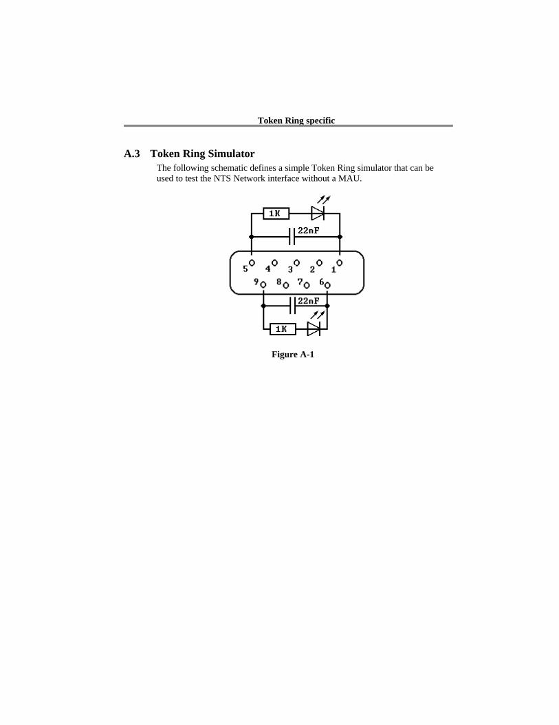
A.3 Token Ring SimulatorThe following schematic defines a simple Token Ring simulator that can beused to test the NTS Network interface without a MAU.
Figure A-1
IP Addresses, Netmask etc.
B- IP Addresses, Netmask etc.
B.1 IP AddressingAn IP address is a 32-bit value, divided into four octets of eight bits each.The standard representation is four decimal numbers (in the range of0..255), divided by dots.Example: 192.2.1.123
This is called decimal-dot notation.
The IP address is divided in two parts: network and host. To supportdifferent needs, three ”network classes” have been defined. Depending onthe network class, the last one, two or three bytes define the host, while theremaining part defines the network. In the following, ‘x’ stands for the hostpart of the IP address:
B.2 Class A NetworkIP address 1.x.x.x to 127.x.x.x
Only 127 different networks of this class exist. These have a very largenumber of potential connected devices (up to 16,777,216)Example: 10.0.0.1, (network 10, host 0.0.1)
B.3 Class B NetworkIP address 128.0.x.x to 191.255.xxx.xxx
These networks are used for large company networks. Every network canconsist of up to 65,534 devices.
Example: 172.1.3.2 (network 172.1, host 3.2)
B.4 Class C NetworkIP address 192.0.0.xxx to 223.255.255.xxx
These network addresses are most common and are often used in smallcompanies. These networks can consist of a maximum number of 254 hosts.Example: 192.7.1.9 (network 192.7.1, host 9)
IP Addresses, Netmask etc.
The remaining addresses 224.x.x.x - 239.x.x.x are defined as ”class D” andare used as a multicast addresses.
The addresses 240.x.x.x. - 254.x.x.x are defined as "class E" and arereserved addresses.
B.5 Network AddressThe host address with all host bits set to "0" is used to address the networkas a whole (in routing entries, for example).
B.6 Broadcast AddressThe address with the host part bits set to ‘1” is the broadcast address,meaning “for every station”.
Network and Broadcast addresses must not be used as a host address (e.g.192.168.0.0 identifies the entire network, 192.168.0.255 identifies thebroadcast address).
B.7 IP NetmaskThe netmask is used to divide the IP address differently from the standarddefined by the classes A, B, C. A netmask defines how many bits from theIP address are to be taken as the network section and how many bits are tobe taken as the host section.
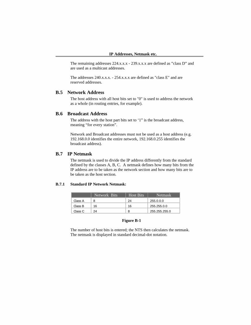
B.7.1 Standard IP Network Netmask:
Network Bits Host Bits NetmaskClass A 8 24 255.0.0.0
Class B 16 16 255.255.0.0
Class C 24 8 255.255.255.0
Figure B-1
The number of host bits is entered; the NTS then calculates the netmask.The netmask is displayed in standard decimal-dot notation.
IP Addresses, Netmask etc.
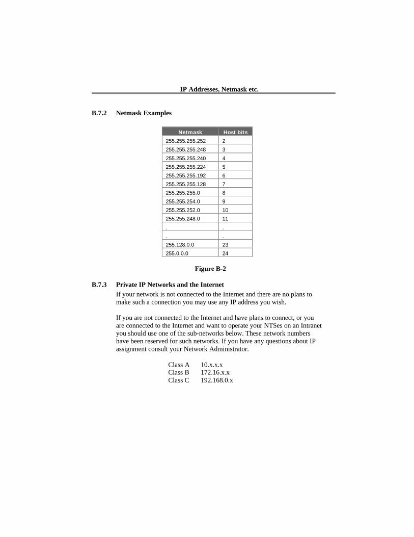
B.7.2 Netmask Examples
Netmask Host bits
255.255.255.252 2
255.255.255.248 3
255.255.255.240 4
255.255.255.224 5
255.255.255.192 6
255.255.255.128 7
255.255.255.0 8
255.255.254.0 9
255.255.252.0 10
255.255.248.0 11
. .
. .
255.128.0.0 23
255.0.0.0 24
Figure B-2
B.7.3 Private IP Networks and the InternetIf your network is not connected to the Internet and there are no plans tomake such a connection you may use any IP address you wish.
If you are not connected to the Internet and have plans to connect, or youare connected to the Internet and want to operate your NTSes on an Intranetyou should use one of the sub-networks below. These network numbershave been reserved for such networks. If you have any questions about IPassignment consult your Network Administrator.
Class A 10.x.x.xClass B 172.16.x.xClass C 192.168.0.x
IP Addresses, Netmask etc.
B.7.4 Network RFC’sFor more information regarding IP addressing see the following documents.These can be located on the World Wide Web using one of the directoriesor indices:
RFC 950 Internet Standard Subnetting ProcedureRFC 1700 Assigned NumbersRFC 1117 Internet NumbersRFC 1597 Address Allocation for Private Internets
Binary to HEX Conversion
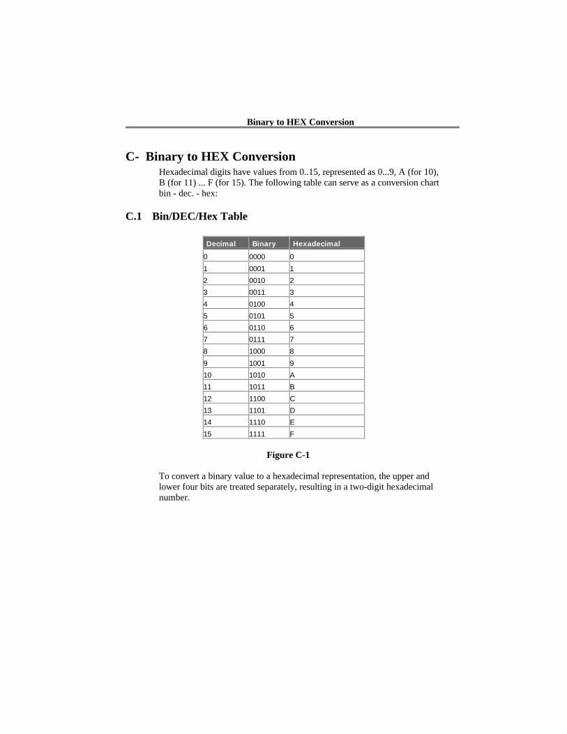
C- Binary to HEX ConversionHexadecimal digits have values from 0..15, represented as 0...9, A (for 10),B (for 11) ... F (for 15). The following table can serve as a conversion chartbin - dec. - hex:
C.1 Bin/DEC/Hex Table
Decimal Binary Hexadecimal
0 0000 0
1 0001 1
2 0010 2
3 0011 3
4 0100 4
5 0101 5
6 0110 6
7 0111 7
8 1000 8
9 1001 9
10 1010 A
11 1011 B
12 1100 C
13 1101 D
14 1110 E
15 1111 F
Figure C-1
To convert a binary value to a hexadecimal representation, the upper andlower four bits are treated separately, resulting in a two-digit hexadecimalnumber.

Warranty Statement
Lantronix warrants for a period of FIVE YEARS from the date ofshipment that each CoBox server supplied shall be free from defects inmaterial and workmanship. During this period, if the customerexperiences difficulties with a product and is unable to resolve theproblem by phone with Lantronix Technical Support, a ReturnMaterial Authorization (RMA) will be issued. Following receipt of aRMA number, the customer is responsible for returning the product toLantronix, freight prepaid. Lantronix, upon verification of warrantywill, at its option, repair or replace the product in question, and returnit to the customer freight prepaid. No services are handled at thecustomer's site under this warranty.
Lantronix warrants software for a period of sixty (60) days from thedate of shipment that each software package supplied shall be freefrom defects and shall operate according to Lantronix specifications.Any software revisions required hereunder cover supply of distributionmedia only and do not cover, or include, any installation. Thecustomer is responsible for return of media to Lantronix and Lantronixfor freight associated with replacement media being returned to thecustomer.
Lantronix shall have no obligation to make repairs or to causereplacement required through normal wear and tear of necessitated inwhole or in part by catastrophe, fault or negligence of the user,improper or unauthorized use of the Product, or use of the Product insuch a manner for which it was not designed, or by causes external tothe Product, such as, but not limited to, power or failure of airconditioning.
There are no understandings, agreements, representations orwarranties, express or implied, including warranties of merchantabilityor fitness for a particular purpose, other than those specifically set outabove or by any existing contract between the parties. Any suchcontract states the entire obligation of Lantronix. The contents of thisdocument shall not become part of or modify any prior or existingagreement, commitment or relationship

The information, recommendation, description and safety notations inthis or other documents supplied by Lantronix are based on generalindustry experience and judgment with respect to such hardware andsoftware. THIS INFORMATION SHOULD NOT BE CONSIDEREDTO BE ALL INCLUSIVE OR COVERING ALL CONTINGENCIES.
NO OTHER WARRANTIES, EXPRESS OR IMPLIED,INCLUDING WARRANTIES OF FITNESS FOR A PARTICULARPURPOSE OR MERCHANTABILITY, OR WARRANTIESARISING FROM COURSE OF DEALING OR USAGE OF TRADE,ARE MADE REGARDING THE INFORMATION,RECOMMENDATIONS, DESCRIPTIONS AND SAFETYNOTATIONS CONTAINED HEREBY AND IN HARDWARE ANDSOFTWARE SPECIFICATION DOCUMENTATION, ORINSTRUCTIONS SUPPLIED BY LANTRONIX. In no event willLantronix be responsible to the user in contract, in tort (includingnegligence), strict liability or otherwise for any special, indirect,incidental or consequential damage or loss of equipment, plant orpower system, cost of capital, loss of profits or revenues, cost ofreplacement power, additional expenses in the use of existingsoftware, hardware, equipment or facilities, or claims against the userby its employees or customers resulting from the use of theinformation, recommendations, descriptions and safety notationssupplied by Lantronix. Lantronix liability is limited (at its election) to(1) refund of buyer's purchase price for such affected products(without interest); (2) repair of such products, or (3) replacement ofsuch products, provided however, that the buyer follows theprocedures set forth herein
Warranty claims must be received by Lantronix within the applicablewarranty period. A replaced product, or part thereof, shall become theproperty of Lantronix and shall be returned to Lantronix at thePurchaser's expense. ALL RETURN MATERIAL MUST BEACCOMPANIED BY A RETURN MATERIAL AUTHORIZATIONNUMBER ASSIGNED BY LANTRONIX.
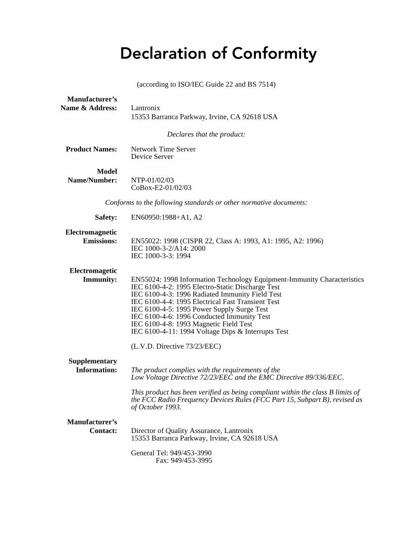
Declaration of Conformity
(according to ISO/IEC Guide 22 and BS 7514)
Manufacturer’sName & Address: Lantronix
15353 Barranca Parkway, Irvine, CA 92618 USA
Declares that the product:
Product Names: Network Time ServerDevice Server
ModelName/Number: NTP-01/02/03
CoBox-E2-01/02/03
Conforms to the following standards or other normative documents:
Safety: EN60950:1988+A1, A2
ElectromagneticEmissions: EN55022: 1998 (CISPR 22, Class A: 1993, A1: 1995, A2: 1996)
IEC 1000-3-2/A14: 2000IEC 1000-3-3: 1994
ElectromageticImmunity: EN55024: 1998 Information Technology Equipment-Immunity Characteristics
IEC 6100-4-2: 1995 Electro-Static Discharge TestIEC 6100-4-3: 1996 Radiated Immunity Field TestIEC 6100-4-4: 1995 Electrical Fast Transient TestIEC 6100-4-5: 1995 Power Supply Surge TestIEC 6100-4-6: 1996 Conducted Immunity TestIEC 6100-4-8: 1993 Magnetic Field TestIEC 6100-4-11: 1994 Voltage Dips & Interrupts Test
(L.V.D. Directive 73/23/EEC)
SupplementaryInformation: The product complies with the requirements of the
Low Voltage Directive 72/23/EEC and the EMC Directive 89/336/EEC.
This product has been verified as being compliant within the class B limits of the FCC Radio Frequency Devices Rules (FCC Part 15, Subpart B), revised as of October 1993.
Manufacturer’sContact: Director of Quality Assurance, Lantronix
15353 Barranca Parkway, Irvine, CA 92618 USA
General Tel: 949/453-3990Fax: 949/453-3995