Embed Size (px)
Citation preview

http://www.omega.com e-mail: [email protected]
omega.com ®
®
User’s Guide
CN3440 SERIESUniversal Temperature & Process
Controllers
Installation Guide
WARRANTY/DISCLAIMEROMEGA ENGINEERING, INC. warrants this unit to be free of defects in materials and workmanship for aperiod of 37 months from date of purchase. OMEGA Warranty adds an additional one (1) monthgrace period to the normal three (3) year product warranty to cover handling and shipping time.This ensures that OMEGA’s customers receive maximum coverage on each product.
If the unit malfunctions, it must be returned to the factory for evaluation. OMEGA’sCustomer Service Department will issue an Authorized Return (AR) number immediately upon phoneor written request. Upon examination by OMEGA, if the unit is found to be defective, it will be repairedor replaced at no charge. OMEGA’s WARRANTY does not apply to defects resulting from any action ofthe purchaser, including but not limited to mishandling, improper interfacing, operation outside ofdesign limits, improper repair, or unauthorized modification. This WARRANTY is VOID if the unit showsevidence of having been tampered with or shows evidence of having been damaged as a result ofexcessive corrosion; or current, heat, moisture or vibration; improper specification; misapplication;misuse or other operating conditions outside of OMEGA’s control. Components which wear are notwarranted, including but not limited tocontact points, fuses, and triacs.
OMEGA is pleased to offer suggestions on the use of its various products. However, OMEGA neither assumes responsibility for any omissions or errors nor assumes liability for any damages that result from the use of its products in accordance with informationprovided by OMEGA, either verbal or written. OMEGA warrants only that the parts manufactured by it will be as specified and free of defects. OMEGA MAKES NO OTHER WARRANTIES OR REPRESENTATIONS OF ANY KIND WHATSOEVER, EXPRESS OR IMPLIED,EXCEPT THAT OF TITLE, AND ALL IMPLIED WARRANTIES INCLUDING ANY WARRANTY OFMERCHANTABILITY AND FITNESS FOR A PARTICULAR PURPOSE ARE HEREBY DISCLAIMED.LIMITATION OF LIABILITY: The remedies of purchaser set forth herein are exclusive, and thetotal liability of OMEGA with respect to this order, whether based on contract, warranty, negligence, indemnification, strict liability or otherwise, shall not exceed the purchase price ofthe component upon which liability is based. In no event shall OMEGA be liable for consequential, incidental or special damages.
CONDITIONS: Equipment sold by OMEGA is not intended to be used, nor shall it be used: (1) as a“Basic Component” under 10 CFR 21 (NRC), used in or with any nuclear installation or activity; or (2) inmedical applications or used on humans. Should any Product(s) be used in or with any nuclearinstallation or activity, medical application, used on humans, or misused in any way, OMEGA assumesno responsibility as set forth in our basic WARRANTY / DISCLAIMER language, and, additionally,purchaser will indemnify OMEGA and hold OMEGA harmless from any liability or damage whatsoeverarising out of the use of the Product(s) in such a manner.
RETURN REQUESTS / INQUIRIESDirect all warranty and repair requests/inquiries to the OMEGA Customer Service Department.BEFORE RETURNING ANY PRODUCT(S) TO OMEGA, PURCHASER MUST OBTAIN AN AUTHORIZEDRETURN (AR) NUMBER FROM OMEGA’S CUSTOMER SERVICE DEPARTMENT (IN ORDER TO AVOIDPROCESSING DELAYS). The assigned AR number should then be marked on the outside of thereturn package and on any correspondence.
The purchaser is responsible for shipping charges, freight, insurance and proper packaging toprevent breakage in transit.
FOR WARRANTY RETURNS, please have thefollowing information available BEFORE contacting OMEGA:1. Purchase Order number under which
the product was PURCHASED,2. Model and serial number of the product under
warranty, and3. Repair instructions and/or specific
problems relative to the product.
FOR NON-WARRANTY REPAIRS, consultOMEGA for current repair charges. Have the following information available BEFORE contacting OMEGA:1. Purchase Order number to cover the COST of
the repair,2. Model and serial number of the product, and3. Repair instructions and/or specific problems
relative to the product.
OMEGA’s policy is to make running changes, not model changes, whenever an improvement is possible. This affords our customers the latest in technology and engineering.OMEGA is a registered trademark of OMEGA ENGINEERING, INC.© Copyright 1998 OMEGA ENGINEERING, INC. All rights reserved. This document may not be copied, photocopied, reproduced, translated, or reduced to any electronic medium or machine-readable form, inwhole or in part, without the prior written consent of OMEGA ENGINEERING, INC.
1
CONTENTS
1 INTRODUCTION .................................. 2
2 PREPARATION .................................... 32.1 Checking the Code Number ......... 3
3 MECHANICAL INSTALLATION .......... 43.1 Siting .......................................... 43.2 Mounting ...................................... 5
4 ELECTRICAL INSTALLATION ............ 64.1 Access to Terminals ..................... 64.2 Setting the Input Selector Links ... 64.3 Setting the Isolated Output Link ... 64.4 Cable Glands and
Conduit Fixings ............................ 84.4.1 Cable Glands
(IEC – 20mm) ................... 84.4.2 Conduit Adaptors
(N. American – 0.5in) ........ 84.4.3 Cable Glands
(N. American – 0.5in) ........ 94.5 Connections Summary ............... 104.6 Input Connections ...................... 12
4.6.1 Thermocouple(THC) Inputs ................... 12
4.6.2 3-lead ResistanceThermometer (RTD)Inputs .............................. 12
4.6.3 2-lead ResistanceThermometer (RTD)Inputs .............................. 12
4.6.4 Links for Unused Inputs .. 124.7 Output Connections ................... 144.8 Relay Connections ..................... 144.9 Motorized Valve Connections .... 144.10 Logic Input Connections ............ 154.11 Power Supply Selection and
AC Connections ......................... 16
5 INSTALLATION RECORD ................. 17
2
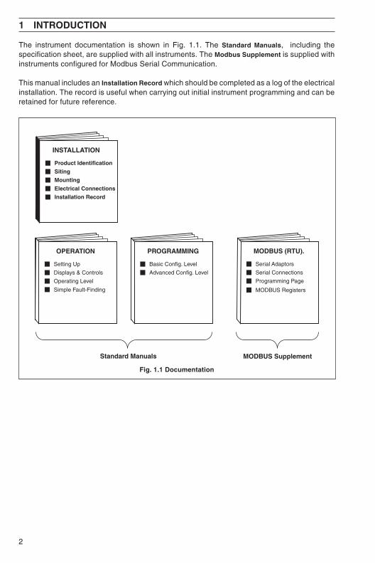
The instrument documentation is shown in Fig. 1.1. The Standard Manuals, including thespecification sheet, are supplied with all instruments. The Modbus Supplement is supplied withinstruments configured for Modbus Serial Communication.
This manual includes an Installation Record which should be completed as a log of the electricalinstallation. The record is useful when carrying out initial instrument programming and can beretained for future reference.
1 INTRODUCTION
PROGRAMMING
Basic Config. Level
Advanced Config. Level
OPERATION
Setting Up
Displays & Controls
Operating Level
Simple Fault-Finding
INSTALLATION
Product Identification
Siting
Mounting
Electrical Connections
Installation Record
MODBUS (RTU).
Serial Adaptors
Serial Connections
Programming Page
MODBUS Registers
Standard Manuals MODBUS Supplement
Fig. 1.1 Documentation
3
2 PREPARATION
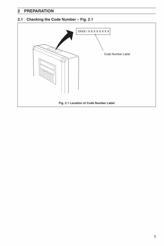
2.1 Checking the Code Number – Fig. 2.1
Fig. 2.1 Location of Code Number Label
Code Number Label
XXXX / X X X X X X X X
4
3 MECHANICAL INSTALLATION
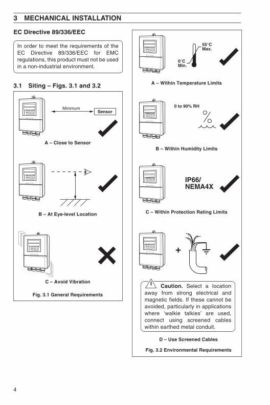
EC Directive 89/336/EEC
In order to meet the requirements of theEC Directive 89/336/EEC for EMCregulations, this product must not be usedin a non-industrial environment.
3.1 Siting – Figs. 3.1 and 3.2 A – Within Temperature Limits
B – Within Humidity Limits
SensorMinimum
A – Close to Sensor
B – At Eye-level Location
Fig. 3.1 General Requirements
C – Avoid Vibration
55°CMax.
0°CMin.
0 to 90% RH
+
IP66/NEMA4X
Caution. Select a locationaway from strong electrical andmagnetic fields. If these cannot beavoided, particularly in applicationswhere ‘walkie talkies’ are used,connect using screened cableswithin earthed metal conduit.
D – Use Screened Cables
Fig. 3.2 Environmental Requirements
C – Within Protection Rating Limits
5
3 MECHANICAL INSTALLATION…
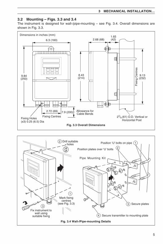
3.2 Mounting – Figs. 3.3 and 3.4The instrument is designed for wall-/pipe-mounting – see Fig. 3.4. Overall dimensions areshown in Fig. 3.3.
Dimensions in inches (mm)
2.68 (68)
8.43(214)
9.13(232)
Fix
ing
Cen
tres
6.3 (160)
9.84(250)
2.72 (69)
Fixing Centres
Allowance forCable Bends7.9 (200)
1.65(42)
23/8 (61) O.D. Vertical orHorizontal Post
Fixing Holes(x3) 0.25 (6.5) Dia
Fig. 3.3 Overall Dimensions
Fig. 3.4 Wall-/Pipe-mounting Details
Mark fixingcentres
(see Fig. 3.3)
Drill suitableholes
Fix instrument towall using
suitable fixing
Position ‘U’ bolts on pipe
Position plates over ‘U’ bolts
Secure transmitter to mounting plate
Secure plates
Pipe Mounting Kit
1
2
3
4
2
1
3
6
4 ELECTRICAL INSTALLATION
Warning. Before making anyconnections, ensure that the powersupply, any high voltage-operated controlcircuits and high common mode voltagesare switched off.
Note.• Always route signal leads and power
cables separately, preferably inearthed metal conduit.
• It is strongly recommended thatscreened cable is used for signalinputs and relay connections. Connectthe screen to the ground stud.
Information. Use cable appropriatefor the load currents. The terminals acceptcables up 12AWG (2.5mm2).
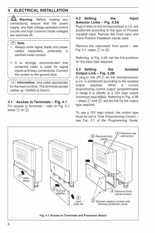
4.1 Access to Terminals – Fig. 4.1For access to terminals – refer to Fig. 4.1,steps 1 to 3.
4.2 Setting the InputSelector Links – Fig. 4.2APlug-in links on the microprocessor p.c.b. arepositioned according to the type of ProcessVariable Input, Remote Set Point Input andValve Position Feedback Inputs used.
Remove the instrument front panel – seeFig. 4.1, steps 1 to 6.
Referring to Fig. 4.2A, set the link positionsfor the input type required.
4.3 Setting the IsolatedOutput Link – Fig. 4.2BA plug-in link (PL7) on the microprocessorp.c.b. is positioned according to the isolatedoutput required, either a currentproportioning control output (programmablein range 0 to 20mA) or a 12V logic output(minimum load 400Ω). Referring to Fig. 4.2B– steps 1 and 2, set the link for the outputtype required.
To use a 12V logic output, the control typemust be set to Time Proportioning Control –see Fig. 3.1 of the Programming Guide.
Fig. 4.1 Access to Terminals and Processor Board
Slacken captive screws andremove protection cover
Remove frontpanel screws
Remove frontpanel
Remove capand screw
4
6
slidedown
1
Pull outslightly…
…andslide off
2
2
5
3
7
4 ELECTRICAL INSTALLATION…
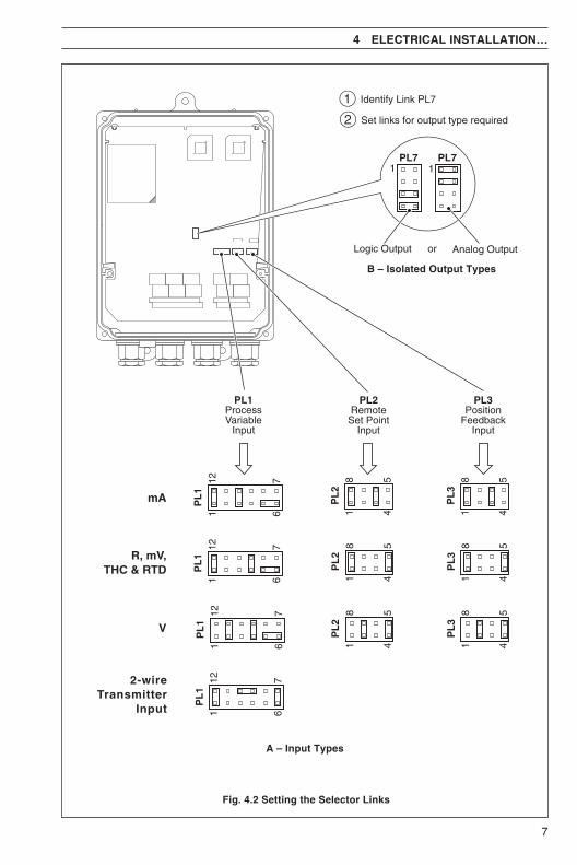
B – Isolated Output Types
Fig. 4.2 Setting the Selector Links
A – Input Types
PL3Position
FeedbackInput
PL2RemoteSet Point
Input
PL1ProcessVariable
Input
PL
2
PL
11 6
12 7
1 4
8 5
PL
1
PL
2
1 6
12 7
1 4
8 5
PL
1
PL
2
1 6
12 7
1 4
8 5
2-wireTransmitter
Input 1 6
12 7
PL
1
1
2
Identify Link PL7
Set links for output type required
mA PL
31 4
8 5
R, mV,THC & RTD P
L3
1 4
8 5
V PL
31 4
8 5
Analog OutputLogic Output or
PL71
PL71
8
…4 ELECTRICAL INSTALLATION
4.4 Cable Glandsand Conduit Fixings
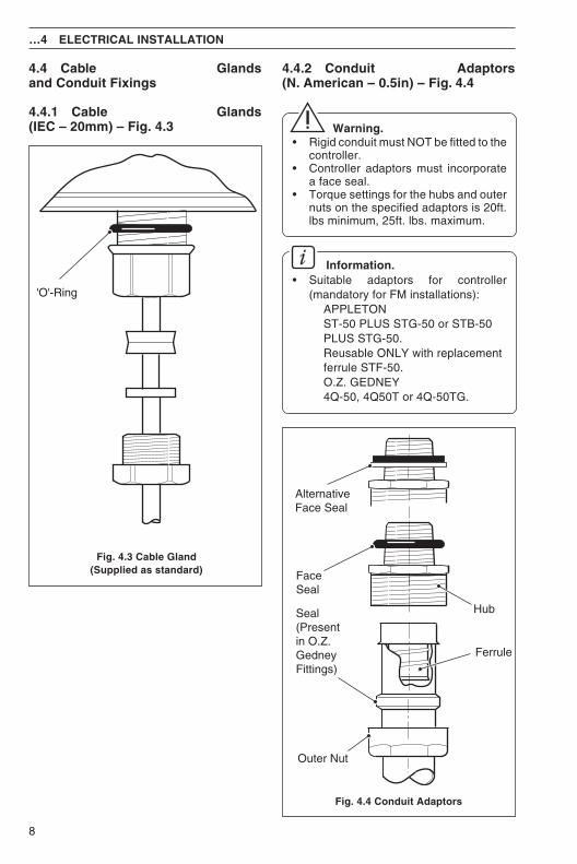
4.4.1 Cable Glands(IEC – 20mm) – Fig. 4.3
4.4.2 Conduit Adaptors(N. American – 0.5in) – Fig. 4.4
Warning.• Rigid conduit must NOT be fitted to the
controller.• Controller adaptors must incorporate
a face seal.• Torque settings for the hubs and outer
nuts on the specified adaptors is 20ft.lbs minimum, 25ft. lbs. maximum.
Information.• Suitable adaptors for controller
(mandatory for FM installations):APPLETONST-50 PLUS STG-50 or STB-50PLUS STG-50.Reusable ONLY with replacementferrule STF-50.O.Z. GEDNEY4Q-50, 4Q50T or 4Q-50TG.
Fig. 4.4 Conduit Adaptors
'O'-Ring
Fig. 4.3 Cable Gland(Supplied as standard)
Ferrule
Outer Nut
Seal(Presentin O.Z.GedneyFittings)
AlternativeFace Seal
FaceSeal
Hub
9
4 ELECTRICAL INSTALLATION…
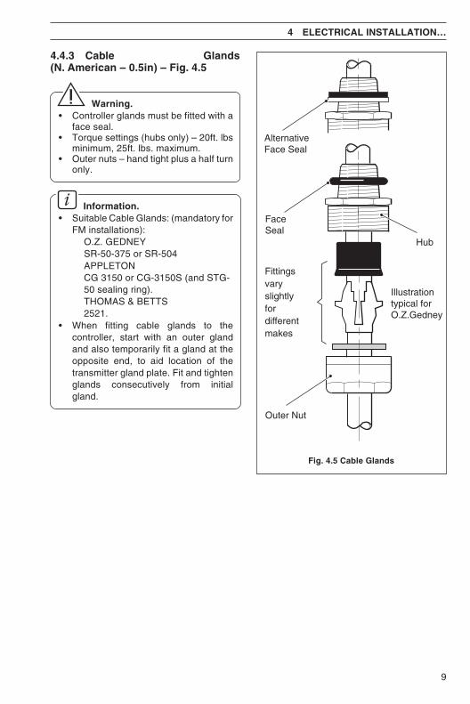
Fig. 4.5 Cable Glands
4.4.3 Cable Glands(N. American – 0.5in) – Fig. 4.5
Warning.• Controller glands must be fitted with a
face seal.• Torque settings (hubs only) – 20ft. lbs
minimum, 25ft. lbs. maximum.• Outer nuts – hand tight plus a half turn
only.
Information.• Suitable Cable Glands: (mandatory for
FM installations):O.Z. GEDNEYSR-50-375 or SR-504APPLETONCG 3150 or CG-3150S (and STG-50 sealing ring).THOMAS & BETTS2521.
• When fitting cable glands to thecontroller, start with an outer glandand also temporarily fit a gland at theopposite end, to aid location of thetransmitter gland plate. Fit and tightenglands consecutively from initialgland.
Fittingsvaryslightlyfordifferentmakes
Outer Nut
AlternativeFace Seal
FaceSeal
Hub
Illustrationtypical forO.Z.Gedney
10
…4 ELECTRICAL INSTALLATION
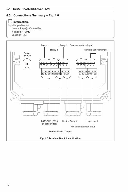
Fig. 4.6 Terminal Block Identification
4.5 Connections Summary – Fig. 4.6
Information.Input impedances:
Low voltage(mV) >10MΩVoltage >10MΩCurrent 10Ω.
3 4 5 6 7 8 9
18 19 20 21 22 23 24 25 26 27 28 29 30 31 32
10 11 12 13 14 15
1 2
16 17
PowerSupply
Relay 1
Relay 2
Relay 3
MODBUS (RTU)(if option fitted)
Retransmission Output
Position Feedback Input
Process Variable Input
Remote Set Point Input
Logic InputControl Output
11
4 ELECTRICAL INSTALLATION…
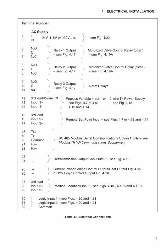
Table 4.1 Electrical Connections
Terminal Number
12
3 N/O4 C5 N/C
6 N/O7 C8 N/C
9 N/O10 C11 N/C
121314
151617
18 Tx+19 Tx–20 Common21 Rx+22 Rx–
23 +24 –
25 +26 –
27 3rd lead28 Input 3+29 Input 3–
303132
3rd lead/2-wire TXInput 1+Input 1–
3rd leadInput 2+Input 2–
Retransmission Output/Cool Output – see Fig. 4.15
Process Variable Input or 2-wire Tx Power Supply– see Figs. 4.7 to 4.9, – see Fig. 4.13 4.12 and 4.14
Remote Set Point Input – see Figs. 4.7 to 4.12 and 4.14
Relay 1 Output Motorized Valve Control Relay (open)– see Fig. 4.17 – see Fig. 4.19A
Relay 2 Output Motorized Valve Control Relay (close)– see Fig. 4.17 – see Fig. 4.19A
Relay 3 Output– see Fig. 4.17
AC SupplyLN
– see Fig. 4.22
Alarm Relays
Position Feedback Input – see Figs. 4.18 , 4.19A and 4.19B
Logic Input 1 – see Figs. 4.20 and 4.21Logic Input 2 – see Figs. 4.20 and 4.21Common
RS 485 Modbus Serial Communications Option 1 only – seeModbus (RTU) Communications Supplement
Current Proportioning Control Output/Heat Output Fig. 4.15or 12V Logic Control Output Fig. 4.16
24V, 115V or 230V a.c.
12
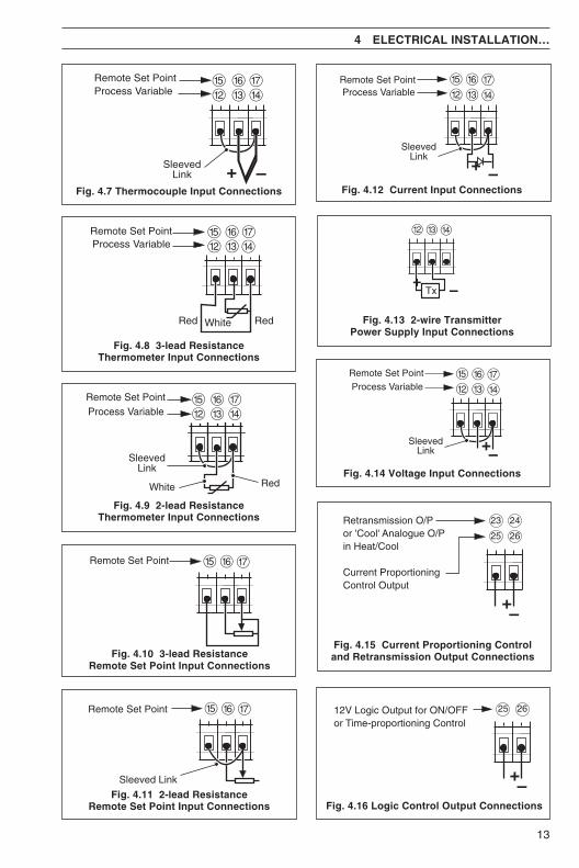
4.6 Input ConnectionsMake connections to each input, as shown in Figs 4.4 to 4.14, first removing any factory-fittedwire links not required.
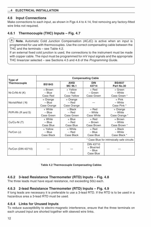
4.6.1 Thermocouple (THC) Inputs – Fig. 4.7
Note. Automatic Cold Junction Compensation (ACJC) is active when an input isprogrammed for use with thermocouples. Use the correct compensating cable between theTHC and the terminals – see Table 4.2.If an external fixed cold junction is used, the connections to the instrument must be madewith copper cable. The input must be programmed for mV input signals and the appropriateTHC linearizer selected – see Sections 4.5 and 4.6 of the Programming Guide.
Table 4.2 Thermocouple Compensating Cables
4.6.2 3-lead Resistance Thermometer (RTD) Inputs – Fig. 4.8The three leads must have equal resistance, not exceeding 50Ω each.
4.6.3 2-lead Resistance Thermometer (RTD) Inputs – Fig. 4.9If long leads are necessary it is preferable to use a 3-lead RTD. If the RTD is to be used in ahazardous area a 3-lead RTD must be used.
4.6.4 Links for Unused InputsTo reduce susceptibility to electro-magnetic interference, ensure that the three terminals oneach unused input are shorted together with sleeved wire links.
…4 ELECTRICAL INSTALLATION
foepyTelpuocomrehT
elbaCgnitasnepmoC
3481SB ISNA1.69CM
NID41734
7394SB03.oNtraP
)K(lA-iN/rC-iNnworB+
eulB–deResaC
wolleY+deR–
wolleYesaC
deR+neerG–
neerGesaC
neerG+etihW–
*neerGesaC
)N(lisiN/lisirciNegnarO+
eulB–egnarOesaC
egnarO+deR–
egnarOesaC—
kniP+etihW–
*kniPesaC
)SdnaR(hR-tP/tPetihW+
eulB–neerGesaC
kcalB+deR–
neerGesaC
deR+etihW–
etihWesaC
egnarO+etihW–
*egnarOesaC
)T(iN-uC/uCetihW+
eulB–eulBesaC
eulB+deR–
eulBesaC
deR+nworB–
nworBesaC
nworB+etihW–
*nworBesaC
)J(noC/eFwolleY+
eulB–kcalBesaC
etihW+deR–
kcalBesaC
deR+eulB–
eulBesaC
kcalB+etihW–
*kcalBesaC
stiucricefasyllacisnirtnirofeulBesaC*
)01734NID(noC/eF — —
01734NIDder/eulB+
eulB–eulBesaC
—
13
&^%Remote Set Point
&^%Remote Set Point
Sleeved Link
$£@&^%
Process VariableRemote Set Point
SleevedLink
RedWhite
Fig. 4.8 3-lead ResistanceThermometer Input Connections
Fig. 4.9 2-lead ResistanceThermometer Input Connections
Fig. 4.10 3-lead ResistanceRemote Set Point Input Connections
Fig. 4.11 2-lead ResistanceRemote Set Point Input Connections
Fig. 4.7 Thermocouple Input Connections
Fig. 4.13 2-wire TransmitterPower Supply Input Connections
Fig. 4.12 Current Input Connections
Fig. 4.14 Voltage Input Connections
Fig. 4.15 Current Proportioning Controland Retransmission Output Connections
Fig. 4.16 Logic Control Output Connections
4 ELECTRICAL INSTALLATION…
£@
SleevedLink
$
Remote Set PointProcess Variable
^% &
–+
Process VariableRemote Set Point
$£@&^%
Red RedWhite
12V Logic Output for ON/OFFor Time-proportioning Control
25 26
–+
Retransmission O/Por 'Cool' Analogue O/Pin Heat/Cool
Current ProportioningControl Output
23
25
24
26
–+
$£@&^%
Process VariableRemote Set Point
SleevedLink
–+
$£@
–+Tx
$£@&^%
Process VariableRemote Set Point
SleevedLink –+
14
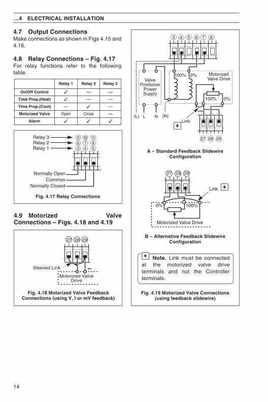
4.7 Output ConnectionsMake connections as shown in Figs 4.15 and4.16.
4.8 Relay Connections – Fig. 4.17For relay functions refer to the followingtable.
A – Standard Feedback SlidewireConfiguration
B – Alternative Feedback SlidewireConfiguration
Note. Link must be connectedat the motorized valve driveterminals and not the Controllerterminals.
…4 ELECTRICAL INSTALLATION
0% 100%
Motorized Valve Drive
27 2928
Link
Fig. 4.19 Motorized Valve Connections(using feedback slidewire)
4.9 Motorized ValveConnections – Figs. 4.18 and 4.19
437609
58!Relay 3
Relay 2Relay 1
Normally ClosedCommon
Normally Open
Fig. 4.17 Relay Connections
2927 28
Motorized ValveDrive
–Sleeved Link+
Fig. 4.18 Motorized Valve FeedbackConnections (using V, I or mV feedback)
1yaleR 2yaleR 3yaleR
lortnoCffO/nO — —
)taeH(.porPemiT — —
)looC(.porPemiT — —
evlaVdezirotoM nepO esolC —
mralA
7 8
(N)NL(L)
MotorizedValve DriveValve
PositionerPowerSupply
0%100%
5 63 4
100%
Link
0%
2927 28
15
31
30
32
Logic Input 2
Manual
Automatic Local
Remoteor Dual
Fixed DualSet Point 2
Fixed DualSet Point 1
* AlarmAcknowledge
* Leading 'edge-triggered'(minimum duration 200ms)
5V
0VLogic switching
Auto/Manual
Selection
Local/RemoteSet PointSelection
Dual Set PointSelection
AlarmAcknowledgement
Common
Logic Input 1
Automatic
Manual
Local
Remote (Dual)
Fixed Dual Set Point 2
Alarm Ack.Fixed Dual Set Point 1
323130
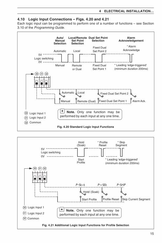
4.10 Logic Input Connections – Figs. 4.20 and 4.21Each logic input can be programmed to perform one of a number of functions – see Section3.10 of the Programming Guide.
Fig. 4.21 Additional Logic Input Functions for Profile Selection
Fig. 4.20 Standard Logic Input Functions
StartProfile
Hold/ (Soak)
Start Profile Profile Reset
Hold(Soak)
* ProfileReset
* SkipSegment
* Leading 'edge-triggered'(minimum duration 200ms)
5V
0VLogic switching
Skip Current Segment
P–SKIPP–Strt P–rSEt
Common
Logic Input 1
Logic Input 2
30
31
32
323130
4 ELECTRICAL INSTALLATION…
Note. Only one function may beperformed by each input at any one time.
Note. Only one function may beperformed by each input at any one time.
16
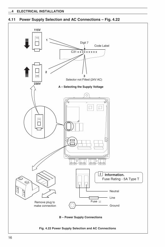
4.11 Power Supply Selection and AC Connections – Fig. 4.22
Fig. 4.22 Power Supply Selection and AC Connections
…4 ELECTRICAL INSTALLATION
Information.Fuse Rating - 5A Type T
115
Selector not Fitted (24V AC)
Code LabelDigit 7
32
1
C31 x x xx x x x x x
115
230
Remove plug tomake connection
A – Selecting the Supply Voltage
B – Power Supply Connections
Line
Neutral
Ground
230V
115V
Fuse
17
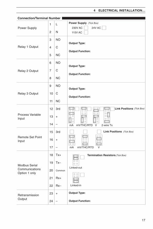
Power Supply1
2
3
4
5
6
7
8
9
10
11
12
13
14
15
16
17
18
19
20
21
22
23
24
L
N
NO
C
NC
NO
C
NC
NO
C
NC
3rd
+
–
3rd
+
–
Tx+
Tx–
Common
Rx+
Rx–
+
–
Connection/Terminal Number
RetransmissionOutput
Relay 1 Output
Relay 2 Output
Power Supply
(Tick Box)
230V AC
115V AC
24V AC
Output Type:
Output Function:
Output Type:
Output Function:
Relay 3 Output
Output Type:
Output Function:
(Tick Box)Link Positions
mA VmV/THC/RTD 2-wire Tx
Process VariableInput
VmA mV/THC/RTD
(Tick Box)Link Positions
Remote Set PointInput
Modbus SerialCommunicationsOption 1 only
(Tick Box)Termination Resistors
Linked-out
Linked-in
Output Type:
Output Function:
4 ELECTRICAL INSTALLATION…
18
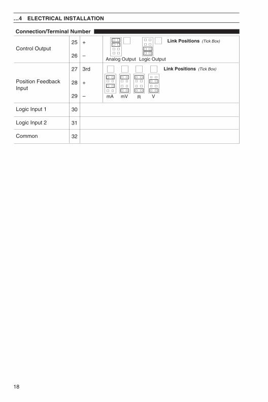
25
26
27
28
29
30
31
32
+
–
3rd
+
–
Connection/Terminal Number
Control Output
Position FeedbackInput
Common
(Tick Box)Link Positions
Analog Output Logic Output
Logic Input 1
Logic Input 2
VmA mV
(Tick Box)Link Positions
R
…4 ELECTRICAL INSTALLATION

19
NOTES

20
…NOTES

Servicing North America:USA: One Omega Drive, Box 4047ISO 9001 Certified Stamford, CT 06907-0047
Tel: (203) 359-1660 FAX: (203) 359-7700e-mail: [email protected]
Canada: 976 BergarLaval (Quebec) H7L 5A1Tel: (514) 856-6928 FAX: (514) 856-6886e-mail: [email protected]
For immediate technical or application assistance:USA and Canada: Sales Service: 1-800-826-6342 / 1-800-TC-OMEGASM
Customer Service: 1-800-622-2378 / 1-800-622-BESTSM
Engineering Service: 1-800-872-9436 / 1-800-USA-WHENSM
TELEX: 996404 EASYLINK: 62968934 CABLE: OMEGAMexico andLatin America: Tel: (95) 800-826-6342 FAX: (95) 203-359-7807
En Espanol: (95) 203-359-7803 e-mail: [email protected]
Servicing Europe:Benelux: Postbus 8034, 1180 LA Amstelveen, The Netherlands
Tel: (31) 20 6418405 FAX: (31) 20 6434643Toll Free in Benelux: 0800 0993344e-mail: [email protected]
Czech Republic: ul. Rude armady 1868, 733 01 Karvina-HraniceTel: 420 (69) 6311899 FAX: 420 (69) 6311114Toll Free: 0800-1-66342 e-mail: [email protected]
France: 9, rue Denis Papin, 78190 TrappesTel: (33) 130-621-400 FAX: (33) 130-699-120Toll Free in France: 0800-4-06342e-mail: [email protected]
Germany/Austria: Daimlerstrasse 26, D-75392 Deckenpfronn, GermanyTel: 49 (07056) 3017 FAX: 49 (07056) 8540Toll Free in Germany: 0130 11 21 66e-mail: [email protected]
United Kingdom: One Omega Drive, River Bend Technology CentreISO 9002 Certified Northbank, Irlam, Manchester
M44 5EX, United Kingdom Tel: 44 (161) 777-6611 FAX: 44 (161) 777-6622Toll Free in the United Kingdom: 0800-488-488e-mail: [email protected]
OMEGAnet® On-Line Service Internet e-mailhttp://www.omega.com [email protected]
It is the policy of OMEGA to comply with all worldwide safety and EMC/EMI regulations that apply. OMEGA is constantly pursuing certification of its products to the European New ApproachDirectives. OMEGA will add the CE mark to every appropriate device upon certification.The information contained in this document is believed to be correct, but OMEGA Engineering, Inc. accepts no liability for any errors it contains, and reserves the right to alter specifications without notice.WARNING: These products are not designed for use in, and should not be used for, patient-connected applications.
omega.com ®
®

M2954/0702
TEMPERATUREThermocouple, RTD & Thermistor Probes, Connectors, Panels & AssembliesWire: Thermocouple, RTD & ThermistorCalibrators & Ice Point ReferencesRecorders, Controllers & Process MonitorsInfrared Pyrometers
PRESSURE, STRAIN AND FORCETransducers & Strain GaugesLoad Cells & Pressure GaugesDisplacement TransducersInstrumentation & Accessories
FLOW/LEVELRotameters, Gas Mass Flowmeters & Flow ComputersAir Velocity IndicatorsTurbine/Paddlewheel SystemsTotalizers & Batch Controllers
pH/CONDUCTIVITYpH Electrodes, Testers & AccessoriesBenchtop/Laboratory MetersControllers, Calibrators, Simulators & PumpsIndustrial pH & Conductivity Equipment
DATA ACQUISITIONData Acquisition & Engineering SoftwareCommunications-Based Acquisition SystemsPlug-in Cards for Apple, IBM & CompatiblesDatalogging SystemsRecorders, Printers & Plotters
HEATERSHeating CableCartridge & Strip HeatersImmersion & Band HeatersFlexible HeatersLaboratory Heaters
ENVIRONMENTALMONITORING AND CONTROL
Metering & Control InstrumentationRefractometersPumps & TubingAir, Soil & Water MonitorsIndustrial Water & Wastewater TreatmentpH, Conductivity & Dissolved Oxygen Instruments
Where Do I Find Everything I Need forProcess Measurement and Control?
OMEGA…Of Course!