Embed Size (px)
Citation preview
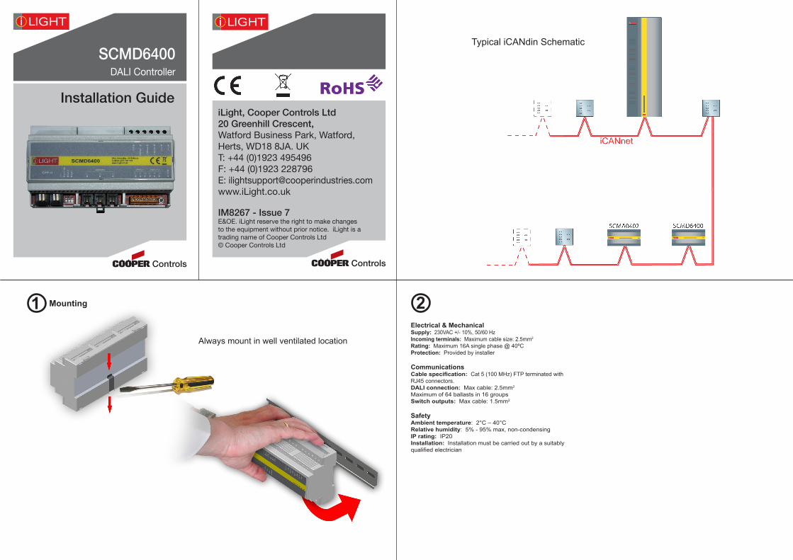
Mounting
SCMD6400DALI Controller
Installation Guide
1 2
iLight, Cooper Controls Ltd20 Greenhill Crescent,Watford Business Park, Watford, Herts, WD18 8JA. UKT: +44 (0)1923 495496F: +44 (0)1923 228796E: [email protected]
Always mount in well ventilated location
IM8267 - Issue 7 E&OE. iLight reserve the right to make changes to the equipment without prior notice. iLight is a trading name of Cooper Controls Ltd © Cooper Controls Ltd
Typical iCANdin Schematic
Electrical & MechanicalSupply: 230VAC +/- 10%, 50/60 HzIncoming terminals: Maximum cable size: 2.5mm2
Rating: Maximum 16A single phase @ 40ºCProtection: Provided by installer
CommunicationsCable specification: Cat 5 (100 MHz) FTP terminated with RJ45 connectors.DALI connection: Max cable: 2.5mm2 Maximum of 64 ballasts in 16 groupsSwitch outputs: Max cable: 1.5mm2
SafetyAmbient temperature: 2°C – 40°CRelative humidity: 5% - 95% max, non-condensingIP rating: IP20Installation: Installation must be carried out by a suitably qualified electrician
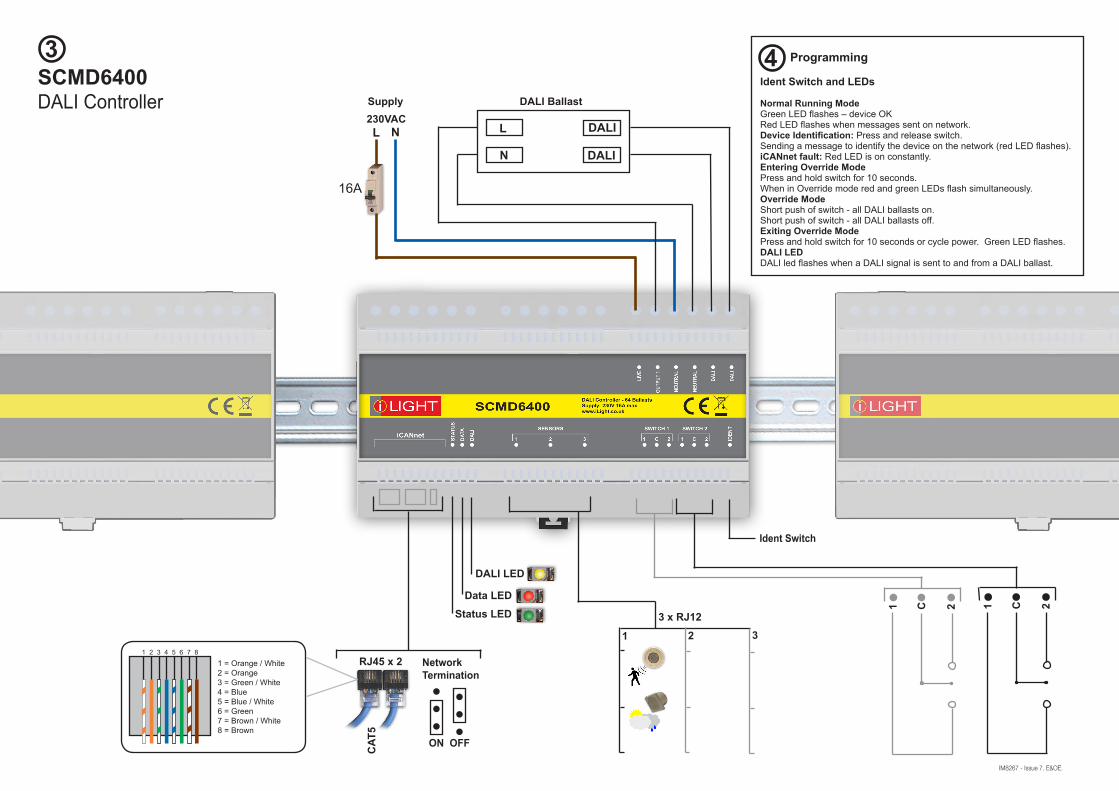
3SCMD6400DALI Controller
IM8267 - Issue 7. E&OE.
CAT
5
RJ45 x 21 2 3 4 5 6 7 8
1 = Orange / White2 = Orange3 = Green / White4 = Blue5 = Blue / White6 = Green7 = Brown / White8 = Brown
L
N
DALI
DALI Ballast
L N230VAC
DALI
Supply
Status LEDData LED
DALI LED
1 C 21 C 2
2 3
Ident Switch
3 x RJ12
NetworkTermination
ON OFF
1
16A
4 Programming
Ident Switch and LEDs
Normal Running ModeGreen LED flashes – device OKRed LED flashes when messages sent on network.Device Identification: Press and release switch.Sending a message to identify the device on the network (red LED flashes).iCANnet fault: Red LED is on constantly.Entering Override ModePress and hold switch for 10 seconds.When in Override mode red and green LEDs flash simultaneously.Override ModeShort push of switch - all DALI ballasts on.Short push of switch - all DALI ballasts off.Exiting Override ModePress and hold switch for 10 seconds or cycle power. Green LED flashes.DALI LEDDALI led flashes when a DALI signal is sent to and from a DALI ballast.