Embed Size (px)
Citation preview

Z207251-0C Page 1 of 42 ©2020 Veris Industries USA 800.354.8556 or +1.503.598.4564 / [email protected] 0420 Alta Labs, Enercept, Enspector, Hawkeye, Trustat, Aerospond, Veris, and the Veris ‘V’ logo are trademarks or registered trademarks of Veris Industries, L.L.C. in the USA and/or other countries.
Other companies’ trademarks are hereby acknowledged to belong to their respective owners.
Installation GuidePower Monitoring TM
DRAFTProduct Identification
Number of Meters Supported
Product OverviewThe E34 Series Multi-Circuit Meters are designed to measure the current, voltage and energy consumption of up to 14 3-phase circuits with a single board or up to 28 3-phase circuits with a 2-board configuration.
The E34 uses commonly available split-core current sensors with 1/3 V (voltage-mode) outputs to cover a wide range of loads.
Data is transmitted using an RS-485 Modbus protocol. E34E models also incorporate Ethernet, with support for BACNet IP, Modbus TCP and SNMP protocols and include BACnet MS/TP serial capability and a sturdy metal enclosure.
The E34 comes pre-configured for 3-phase loads, but can easily be configured on site to accommodate any combination of 3-phase, 2-phase and single-phase loads, with or without Neutral current, using the channels available on the model selected (see table below).
To configure the E34 for operation, use the NetConfig configuration software tool and the E3x Commissioning Guide on the USB drive provided.
E34 SeriesMulti-Circuit Meters
E34
Communication Option
Number of 3-Phase Meters
A = Modbus RTU onlyE = Integrated Ethernet with Modbus, BACnet & SNMP
04 = 4 (3-phase) meters08 = 8 (3-phase) meters14 = 14 (3-phase) meters28 = 28 (3-phase) meters
E34A Modbus RTU Only
E34E Integrated Ethernet
Number of Meters
3-Phase 2-Phase 1-Phase
E34A04 E34E04 4 6 12
E34A08 E34E08 8 12 24
E34A14 E34E14 14 21 42
E34A28 E34E28 28 42 84
E34E
E34A
E212445

Z207251-0C Page 2 of 42 ©2020 Veris Industries USA 800.354.8556 or +1.503.598.4564 / [email protected] 0420 Alta Labs, Enercept, Enspector, Hawkeye, Trustat, Aerospond, Veris, and the Veris ‘V’ logo are trademarks or registered trademarks of Veris Industries, L.L.C. in the USA and/or other countries.
Other companies’ trademarks are hereby acknowledged to belong to their respective owners.
E34 Series Installation GuideTM
Safety Information
Control system design must consider the potential failure modes of control paths and, for certain critical control functions, provide a means to acheive a safe state during and after a path failure. Examples of critical control functions are emergency stop and over-travel stop.
For additional information about anticipated transmission delays or failures of the link, refer to NEMA ICS 1.1 (latest edition). Safety Guidelines for the Application, Installation, and Maintenance of Solid-State Controls or its equivalent in your speci�c country, language, and/or location.
LOSS OF CONTROL• Ensure that the system will reach a safe state during and after a control path failure.• Separate or redundant control paths must be provided for critical control functions.• Test the effect of transmission delays or failures of communication links.• Each implementation of equipment using communication links must be individually and thoroughly tested for proper operation before placing
it in service.Failure to follow these instructions can result in death or serious injury.
WARNING
Provide a disconnect device to disconnect the meter from the supply source. Place this device in close proximity to the equipment and within easy reach of the operator, and mark it as the disconnecting device. The disconnecting device shall meet the relevant requirements of IEC 60947-1 and IEC 60947-3 and shall be suitable for the application. In the US and Canada, disconnecting fuse holders can be used. Provide overcurrent protection and disconnecting device for supply conductors with approved current limiting devices suitable for protecting the wiring.
FCC PART 15 INFORMATIONE34A Models: This equipment has been tested and found to comply with the limits for a Class B digital device, pursuant to Part 15 of the FCC rules. These limits
are designed to provide reasonable protection against harmful interference in a residential installation. This equipment generates, uses, and can radiate radio frequency energy and, if not installed and used in accordance with the instructions, may cause harmful interference to radio communications. However, there is no guarantee that interference will not occur in a particular installation. If this equipment does cause harmful interference to radio or television reception, which can be determined by turning the equipment o� and on, the user is encouraged to try to correct the interference by one or more of the following measures:
– Reorient or relocate the receiving antenna. – Increase the separation between the equipment and receiver. – Connect the equipment to an outlet on a circuit di�erent from that of the receiver. – Consult the dealer or an experienced radio/TV technician for help.The user is cautioned that any changes or modi�cations not expressly approved by Veris Industries could void the user’s authority to operate the equipment.
E34E Models: This equipment has been tested and found to comply with the limits for a Class A digital device, pursuant to part 15 of the FCC Rules. These limits are designed to provide reasonable protection against harmful interference when the equipment is operated in a commercial environment. This equipment generates, uses, and can radiate radio frequency energy and, if not installed and used in accordance with the instruction manual, may cause harmful interference to radio communications. Operation of this equipment in a residential area is likely to cause harmful interference in which case the user will be required to correct the interference at his own expense.
CAN ICES-3 (B) /NMB-3(B)
If this product is used in a manner not speci�ed by the manufacturer, the protection provided by the product may be impaired.The installer is responsible for conformance to all applicable codes.The safety of any system incorporating this equipment is the responsibility of the assembler of the system.Note: See IEC 60950-1:2005, Annex W for more information on communications and I/O wiring connected to multiple devices. Protective bonding: electrical connection of accessible conductive parts or protective screening to provide electrical continuity to the means for connection of an external protective conductor.
HAZARD OF ELECTRIC SHOCK, EXPLOSION, OR ARC FLASH• This product must be installed inside a suitable fire and electrical enclosure.• Follow safe electrical work practices. See NFPA 70E in the USA, or applicable local codes.• This equipment must only be installed and serviced by qualified electrical personnel.• Do not use this device for critical control or protection applications where human or equipment safety relies on the operation of the control
circuit.• Do not install this product in hazardous or classified locations.• Read, understand and follow the instructions before installing this product.• Turn off all power supplying equipment before working on or inside the equipment.• Product may use multiple voltage/power sources. Disconnect all sources before servicing.• Use a properly rated voltage sensing device to confirm that power is off. • Do not use data from this device to confirm power is off.• Replace all doors, covers and protective devices before powering the equipment.• Do not exceed the product's ratings or maximum limits.• Treat communications and I/O wiring connected to multiple devices as hazardous live until determined otherwise.Failure to follow these instructions will result in death or serious injury.
DANGER

Z207251-0C Page 3 of 42 ©2020 Veris Industries USA 800.354.8556 or +1.503.598.4564 / [email protected] 0420 Alta Labs, Enercept, Enspector, Hawkeye, Trustat, Aerospond, Veris, and the Veris ‘V’ logo are trademarks or registered trademarks of Veris Industries, L.L.C. in the USA and/or other countries.
Other companies’ trademarks are hereby acknowledged to belong to their respective owners.
E34 Series Installation GuideTM
MEASUREMENTS
Measurement Voltage 90 to 300 Vac line-to-neutral, 50/60 Hz
Total Harmonic Distortion (THD) THD % voltage line-to-line, line-to-neutral and THD % on current
CONTROL POWER
E34A 90 to 277 Vac line-to-neutral, 50/60Hz, 8 VA
E34E 100 to 277 Vac line-to-neutral, 50/60Hz, 15 VA
ACCURACY
Power/Energy IEC 62053-21 Class 0.5, ANSI C12.20 class 0.5
Voltage ±0.5% of reading 90 to 277 V line-to-neutral
Current ±0.5% of reading from 2% to 100% of full-scale
OPERATION
Sampling Frequency 2560 Hz
Update Rate 1.8 seconds (both panels)
Overload Capability 22 kAIC
E34A SERIAL COMMUNICATION
Type Modbus RTU
Connection DIP switch-selectable 2-wire or 4-wire, RS-485
Address DIP switch-selectable address 1 to 247 (in pairs of 2)*
Baud Rate DIP switch-selectable 9600, 19200, 38400
Parity DIP switch-selectable NONE, ODD, EVEN
Communication Format 8 data bits, 1 start bit, 1 stop bit
Termination 5-position plug-in connector (TX+ TX- SHIELD TX+/RX+ TX-/RX-)
E34E SERIAL COMMUNICATION
Physical Interface 2-wire RS-485
Serial Protocols Supported Modbus RTU or BACnet MS/TP
Address Range 1 to 247 for Modbus RTU; 0 to 127 for BACnet MS/TP
Baud Rate 9600, 19200, 38400
Parity Modbus RTU: NONE, ODD, EVEN BACnet MS/TP: NONE (fixed)
Communication Format 8 data bits, 1 start bit, 1 stop bit
Termination 2x3 position connector
E34E ETHERNET COMMUNICATION
Physical Interface RJ45 connector with 10/100 Mbit Ethernet
Protocols Supported Modbus TCP, BACnet IP, SNMP V2c
WIRE SIZE RANGE
Removable Connectors on Main Board 22 to 12 AWG
CT Terminals and E34E Serial Connector Terminals
26 to 16 AWG
TERMINAL BLOCK TORQUE
Removable Connectors 4.4 to 5.3 in-lb (0.5 to 0.6 N-m)
MECHANICAL
Ribbon Cable Support (28-meter models only)
4 ft. (0.9 m) round ribbon cable ships standard; up to 20 ft. (6 m) flat or round available
OPERATING CONDITIONS
Operating Temperature Range 0 to 60 °C (32 to 140 °F) (<95% RH non-condensing)
Storage Temperature Range -40 to 70 °C (-40 to 158 °F)
Altitude of Operation 3000 m
Mounting Location Not suitable for wet locations. For indoor use only.
Specifications

Z207251-0C Page 4 of 42 ©2020 Veris Industries USA 800.354.8556 or +1.503.598.4564 / [email protected] 0420 Alta Labs, Enercept, Enspector, Hawkeye, Trustat, Aerospond, Veris, and the Veris ‘V’ logo are trademarks or registered trademarks of Veris Industries, L.L.C. in the USA and/or other countries.
Other companies’ trademarks are hereby acknowledged to belong to their respective owners.
E34 Series Installation GuideTM
Specifications (cont.) COMPLIANCE INFORMATION
Agency Approvals UL508**, IEC/EN61010-1
Installation Category Cat III, Pollution Degree 2***
Conducted Emissions E34A Models: FCC part 15 Class B, EN61000-6-3, EN61326-1 Class B (residential and light industrial)
Radiated Emissions E34E Models: FCC part 15 Class A, EN6100-6-4, EN61326-1 Class A
Conducted and Radiated Immunity EN 61000-6-2 and EN 61326-1
* See Configuration section for details.**The E34 must be installed in an appropriate electrical and fire enclosure per local regulations. If E34 products are used in
installations with circuits higher than the product ratings, the circuits must be kept segregated per UL508A Sec. 17.5. Note: E34 internal circuitry (cables and CTs) are not circuits as defined by UL508A, as they do not extend beyond the E34 itself without further safety/fire isolation.
*** A Pollution Degree 2 environment must control conductive pollution and the possibility of condensation or high humidity. Consideration must be given to the enclosure, the correct use of ventilation, thermal properties of the equipment and the relationship with the environment.

Z207251-0C Page 5 of 42 ©2020 Veris Industries USA 800.354.8556 or +1.503.598.4564 / [email protected] 0420 Alta Labs, Enercept, Enspector, Hawkeye, Trustat, Aerospond, Veris, and the Veris ‘V’ logo are trademarks or registered trademarks of Veris Industries, L.L.C. in the USA and/or other countries.
Other companies’ trademarks are hereby acknowledged to belong to their respective owners.
E34 Series Installation GuideTM
Table of Contents Dimensions 6
Product Diagrams 7
Data Outputs 9
Blink Codes for Status LED 10
Installation 11
Wiring 15
Configuration 18
Default DIP Switch Settings 20
Address Selection 21
Gateway Configuration 22
BACnet PICS 32
General BACnet Programming Information 33
General SNMP Programming Information 34
Commissioning 34
Cybersecurity 35
Recommended Accessories 41
Troubleshooting 41
China RoHS Compliance Information (EFUP Table) 42

Z207251-0C Page 6 of 42 ©2020 Veris Industries USA 800.354.8556 or +1.503.598.4564 / [email protected] 0420 Alta Labs, Enercept, Enspector, Hawkeye, Trustat, Aerospond, Veris, and the Veris ‘V’ logo are trademarks or registered trademarks of Veris Industries, L.L.C. in the USA and/or other countries.
Other companies’ trademarks are hereby acknowledged to belong to their respective owners.
E34 Series Installation GuideTM
Dimensions E34A Base Board
7.3”(184 mm)
8.9”(226 mm)
5.8”(146 mm)
4.8”(122 mm)
3.9”(100 mm)
7.9”(200 mm)
8.3”(211 mm)
1.75”(45 mm)
Ø = 0.2”(5 mm)
E34E Main Unit
13.9”(353 mm)
2x: 5.9”(150 mm)
12.8”(325 mm)
8.9”(225 mm)
10.0”(253 mm)
12.1”(307 mm)
8.2”(210 mm)
2.8”(71 mm)
1.74”(44 mm)
Z207251-0C Page 7 of 42 ©2020 Veris Industries USA 800.354.8556 or +1.503.598.4564 / [email protected] 0420 Alta Labs, Enercept, Enspector, Hawkeye, Trustat, Aerospond, Veris, and the Veris ‘V’ logo are trademarks or registered trademarks of Veris Industries, L.L.C. in the USA and/or other countries.
Other companies’ trademarks are hereby acknowledged to belong to their respective owners.
E34 Series Installation GuideTM
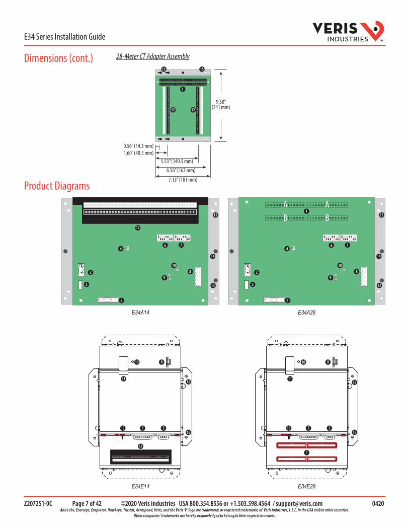
Product Diagrams
Dimensions (cont.) 28-Meter CT Adapter Assembly
9.50”(241 mm)
7.13” (181 mm)
6.56” (167 mm)
5.53” (140.5 mm)1.60” (40.5 mm)0.56” (14.3 mm)
1515
12
1
12
E34E14 E34E28
E34A28E34A14
6
1
2
3
4
5
7
89
A AB B
10
15
13
14
6
2
3
4
5
7
89
10
15
13
14
12
8 8
5 2
10 10
11 1115
15 15
15
12
13 5 2
1
13

Z207251-0C Page 8 of 42 ©2020 Veris Industries USA 800.354.8556 or +1.503.598.4564 / [email protected] 0420 Alta Labs, Enercept, Enspector, Hawkeye, Trustat, Aerospond, Veris, and the Veris ‘V’ logo are trademarks or registered trademarks of Veris Industries, L.L.C. in the USA and/or other countries.
Other companies’ trademarks are hereby acknowledged to belong to their respective owners.
E34 Series Installation GuideTM
Product Diagram (cont.)
1. 50-pin ribbon cable connectors (E34A28 and E34E28 only): Ribbon cables attach here for easy connection of adapter boards to the data acquisition board. The two connectors on the left are for panelboard 1; the two on the right are for panelboard 2.
Note: Connect Adapter Board Connectors A and B to the correct ribbon cable connectors for each panel. The top connectors are for Adapter Board Connector A, and the bottom connectors are for Adapter Board Connector B.
Note: The standard ribbon cable included with E34A28 and E34E28 is 4 feet long (1.2 meters). For other ribbon cable options, see the Recommended Accessories section.
2. Control power connection: Provides power to operate the meter
3. Control power fuse: 600 Vac, 500 mA time lag, factory-replaceable
4. Alive LED (E34A models): Red/green/amber LEDs. Blink codes are described in the Blink Codes for Status LED section of this document.
5. Voltage taps: 1, 2, or 3 phase plus neutral connections. For voltage sensing and power calculations. Voltage taps are shared by all meters (including both logical panels on 28-meter models).
6. Communications address DIP switch (E34A models): Each Modbus device must have a unique address. Switches are binary weighted. Left-most switch has a value of 1; right-most switch has a value of 128. Note: switches set the address for panel 1; panel 2 is automatically set to (Panel 1 address + 1). See Configuration section for details.
7. Communications settings DIP switch (E34A models): Configures baud rate, parity, 2- or 4-wire communications.
8. RS-485 connection: Used for Modbus serial communications. The Universal plug accommodates 2 or 4 wire connections.
9. RS-485 LEDs (E34A models): The RX LED (closest to DIP switches) indicates the RS-485 is receiving information; the TX LED indicates transmission of information.
10. Power LED: Indicates power to the E34
11. Ethernet connection (“E” models only)
12. CT lead connections
13. Ground terminal
14. Mounting studs for optional plexiglas cover (AE001)
15. Holes for mounting the E34

Z207251-0C Page 9 of 42 ©2020 Veris Industries USA 800.354.8556 or +1.503.598.4564 / [email protected] 0420 Alta Labs, Enercept, Enspector, Hawkeye, Trustat, Aerospond, Veris, and the Veris ‘V’ logo are trademarks or registered trademarks of Veris Industries, L.L.C. in the USA and/or other countries.
Other companies’ trademarks are hereby acknowledged to belong to their respective owners.
E34 Series Installation GuideTM
The E34 provides several types of measurements that give a comprehensive view of power consumption for every load on the panel (the table below shows which measurements are offered on each model):
• Real-time measurements: A live and up-to-date view of present power levels and the factors that affect them.• Demand measurements: Averages of values measured over a specified time interval. The time interval (typically 15
minutes) can be set from 10 seconds to more than a day. The demand calculation can be configured to use single intervals or the sliding average of up to six sub-intervals. Demand measurements are useful for tracking or graphing load levels over time to correlate with total energy consumption.
• Historic maximum measurements: These measurements store the largest value recorded for a specific measurement since the last time they were cleared. They are useful for identifying peak levels critical to equipment sizing or demand limits in utility agreements.
• Accumulated energy measurements: Ongoing totals of cumulative energy used since the last time the value was cleared. Energy values provide the informational basis for billing, cost allocation, carbon offset, BTU equivalent calculations, and other applications of overall energy use.
• Energy snapshots: Energy totals that only change when the demand intervals are updated. They are samples of the free-running energy accumulators at the end of each demand interval, as configured by the user. These provide energy readings that are easily correlated to the demand values to simplify the tasks of sub-billing and cost allocation.
• Alarms: Informs of excessively high or low current on each branch and aux channel. The user can set two high-level and two low-level thresholds, and a delay time for latching alarms. Alarms are reported as both non-latched events and latched events. Non-latching alarms are active while the current exceeds the threshold, but go inactive if the current returns to a level within the specific thresholds. Latching alarms become active when the current exceeds the threshold for a time period greater than the specified delay and remain active until they are cleared remotely.
• Alarm status can be polled via Modbus. Advanced Features - The E34 also supports a number of advanced features. Some are always active, and others are configured manually via Modbus register 62017). For models with 42 channels or more, these features are configured independently for each panel.
• Logical meter support: The E34 can be configured to map any set of 1, 2 or 3 channels that are adjacent in the panel to a logical meter, referred to in the point map as a logical circuit, that provides accurate multi-phase measurement totals. Map these logical circuits by writing the desired logical circuit number into a set of registers/data objects provided for each branch and aux channel (per panel).
• The channels assigned to each logical circuit must be adjacent in the panel (for example, channels 5, 6 and 7), but there are no limitations on where those adjacent channels are aligned in the panel (any position where a multi-phase breaker can be installed). This functionality is always active, but a user selection affects how the data can be accessed via Modbus. Measurement data via Modbus for logical circuits is presented in two ways: arranged either by logical circuit number (looks more like a collection of individual meters) or by measurement type (arranged similar to the single-phase data section of the point map).
• Phase angle measurements: The E34 measures the phase angle of every voltage and current input and presents these measurements (in degrees) in additional data registers/objects. These values are used to verify that current inputs are assigned to the proper voltage phases and to help determine how power factor variations are influenced by current phase changes vs. harmonic distortion. Phase angle measurements are instantaneous and always active.
• User CT phase assignment: By default, the E34 assigns each CT channel to voltage phases on a rotating sequence. The user can easily override the default phase assignments as needed to accommodate their specific application or miswiring of phases on installation. The explicit assignments set by the user are stored by the E34 in non-volatile memory.
• Phase angle reference: The E34 measures the phase angle of every current and voltage input. The user can select whether the phase angles are stated relative to an absolute reference (the phase angle of voltage input V1) or relative to the voltage phase assigned to that specific current input channel.
• Signed power: Users can configure the E34 to report power as a signed value indicating whether the power is currently being delivered (imported from the grid) or received (exported to the grid) for channels with generation sources or bi-directional (regenerative) loads. When signed power is disabled, the energy accumulators include all energy measured, regardless of direction. When signed power is enabled, the energy accumulators only include all energy delivered (imported from the grid).
• Signed power factor: By default, the E34 reports power factor as an unsigned value. The user can set it to report as a signed value, where the sign indicates whether the current phase angle leads or lags the corresponding voltage phase.
• Demand/snapshot time interval source: The E34 offers two mechanisms for driving the demand/snapshot time interval, an interval timer or an RTC (real-time clock). The legacy mode (default) uses an interval timer that does not need to be set to an absolute time. When using the interval timer the demand/snapshot interval can be set from
Data Outputs

Z207251-0C Page 10 of 42 ©2020 Veris Industries USA 800.354.8556 or +1.503.598.4564 / [email protected] 0420 Alta Labs, Enercept, Enspector, Hawkeye, Trustat, Aerospond, Veris, and the Veris ‘V’ logo are trademarks or registered trademarks of Veris Industries, L.L.C. in the USA and/or other countries.
Other companies’ trademarks are hereby acknowledged to belong to their respective owners.
E34 Series Installation GuideTM
10 to 32,767 seconds (over 9 hours). An alternate mode utilizes an RTC set to a specific date and time to synchronize the results with a larger system. The RTC must first be set in order to run and capture demand values and energy snapshots. When power is interrupted, the RTC resets to a default date and time and must be set again in order to run. When using the RTC, the demand/snapshot interval can be set from 10 to 3,600 seconds (1 hour).
Measurements
Real Time Measurements
Current: multi-phase average and per phase
Current phase angle per branch
Real power (kW): multi-phase total and per phase
Apparent power (kVA): multi-phase total and per phase
Power factor: multi-phase average and per phase
Demand MeasurementsCurrent present demand: multi-phase average and per phase
Real power (kW) present demand: multi-phase average and per phase
Historic Maximums
Maximum instantaneous current: multi-phase average and per phase
Maximum current demand: multi-phase average and per phase
Maximum real power demand: multi-phase total and per phase
Accumulated Energy Energy (kWh): multi-phase total and per phase
Energy Snapshots Energy (kWh): multi-phase total and per phase
Modbus Alarms
Alarms
Voltage over/under
Branch current over/under
Mains current over/under
Color and Pattern Status Description
Green, once per second Normal operation
Amber, once per second Volts or amps clipping
Amber, twice per second Invalid firmware image
Red, solid or blink Diagnostic event detected
Data Outputs (cont.)
Blink Codes for Status LED (E34A Models Only)

Z207251-0C Page 11 of 42 ©2020 Veris Industries USA 800.354.8556 or +1.503.598.4564 / [email protected] 0420 Alta Labs, Enercept, Enspector, Hawkeye, Trustat, Aerospond, Veris, and the Veris ‘V’ logo are trademarks or registered trademarks of Veris Industries, L.L.C. in the USA and/or other countries.
Other companies’ trademarks are hereby acknowledged to belong to their respective owners.
E34 Series Installation GuideTM
ESD-SENSITIVE DEVICESObserve handling precautions for static sensitive devices.Failure to follow this instruction can result in damaged circuitry and loss of factory warranty.
NOTICE
HAZARD OF ELECTRIC SHOCK, EXPLOSION, OR ARC FLASH• This product must be installed inside a suitable fire and electrical enclosure.• Follow safe electrical work practices. See NFPA 70E in the USA, or applicable local codes.• This equipment must only be installed and serviced by qualified electrical personnel.• Do not use this device for critical control or protection applications where human or equipment safety
relies on the operation of the control circuit.• Do not install this product in hazardous or classified locations.• Read, understand and follow the instructions before installing this product.• Turn off all power supplying equipment before working on or inside the equipment.• Product may use multiple voltage/power sources. Disconnect all sources before servicing.• Use a properly rated voltage sensing device to confirm that power is off. • Replace all doors, covers and protective devices before powering the equipment.• Do not exceed the product's ratings or maximum limits.• Treat communications and I/O wiring connected to multiple devices as hazardous live until determined
otherwise.• Use the protective ground connection on the mounting bracket if the device is not mounted to a
suitable ground surface..Failure to follow these instructions will result in death or serious injury.
DANGER
1. Turn off all power supplying this device and the equipment in which it is installed before working on the device or equipment.2. Always use a properly rated voltage sensing device to confirm power is off.3. Install the acquisition board mounting bracket in the panel. Panels can be oriented side-by-side (Figure 1A) or vertically (Figure
1B). A grounding connection is located on the mounting bracket, near the lower right corner.
Figure 1APanel 1 Panel 2
GroundE34A
Figure 1BPanel 1
Panel 2
Main Circuit Board
Installation

Z207251-0C Page 12 of 42 ©2020 Veris Industries USA 800.354.8556 or +1.503.598.4564 / [email protected] 0420 Alta Labs, Enercept, Enspector, Hawkeye, Trustat, Aerospond, Veris, and the Veris ‘V’ logo are trademarks or registered trademarks of Veris Industries, L.L.C. in the USA and/or other countries.
Other companies’ trademarks are hereby acknowledged to belong to their respective owners.
E34 Series Installation GuideTM
Installation (cont.) 4. Determine where you will mount the E34 measurement unit. The preferred location is inside the enclosure of the panelboard being monitored. If sufficient space is not available there, mount the unit in an appropriate enclosure nearby. Decide whether to mount the E34 vertically or horizontally. The E34 is shipped with the brackets placed on the two sides for vertical mounting. If desired, you can move the brackets from the sides to the ends of the housing. Loosen the screws on the sides of the E34 that hold the brackets in place. Do not fully remove the screws from the E34 housing. Loosen the screws on the two ends of the housing (without fully removing the screws from the housing), and set the brackets into their new positions. Tighten all screws.
Figure 2
Vertical and HorizontalMounting Options
E34E
Vertica & HorizontalMounting Options
5. On E34A28 or E34E28 models, connect the 28-meter adapter assembly to the meter using the ribbon cables supplied. To order different length cables, see the list of Recommended Accessories.
6. The E34 supports CTs with voltage mode outputs (0.333V full-scale). Install the current sensors onto the conductors to be monitored according to the instructions provided with the CTs.
28-MeterCT Adapter
Board
E34A28
E34E28
Figure 3

Z207251-0C Page 13 of 42 ©2020 Veris Industries USA 800.354.8556 or +1.503.598.4564 / [email protected] 0420 Alta Labs, Enercept, Enspector, Hawkeye, Trustat, Aerospond, Veris, and the Veris ‘V’ logo are trademarks or registered trademarks of Veris Industries, L.L.C. in the USA and/or other countries.
Other companies’ trademarks are hereby acknowledged to belong to their respective owners.
E34 Series Installation GuideTM
Installation (cont.)EQUIPMENT DAMAGEDo not use CTs with current-mode outputs.Failure to follow this instruction can result in equipment damage.
NOTICE
Figure 4
X2
X1
X2
X1
X2
X1
X2
X1
Figure 5
E34A
E34E
7. Strip 9 mm of insulation from the end of the CT leads. A visual strip length indicator is provided on the CT adapter board to show how much to strip.
Figure 6
Strip LengthIndicatorLocations
28-Meter CT Adapter Board

Z207251-0C Page 14 of 42 ©2020 Veris Industries USA 800.354.8556 or +1.503.598.4564 / [email protected] 0420 Alta Labs, Enercept, Enspector, Hawkeye, Trustat, Aerospond, Veris, and the Veris ‘V’ logo are trademarks or registered trademarks of Veris Industries, L.L.C. in the USA and/or other countries.
Other companies’ trademarks are hereby acknowledged to belong to their respective owners.
E34 Series Installation GuideTM
8. To connect the stripped CT leads, press the square button on the desired connector input, insert the stripped end of the wire completely, and release the button.
9. Insert the x1 lead (white wire on Veris CTs) to the inputs on the white connector and the x2 lead (black wire on Veris CTs) to the inputs on the black connector.
10. Plastic cable ties are included with the product for strain relief on the E34A28 and E34E28. Insert the strain relief device into one of the available holes on the adapter board (Figure 7A). Gather all current sensor wires connected to that adapter board and secure the cable tie around them (Figure 7B).
Figure 7A B
11. The adapter boards are silk screened with labeling for the default configuration of all 3-phase meters. Alternate label overlays are provided for configurations with all 2-phase meters or all single-phase meters. Channel numbers are provided as well for setting up and using custom configurations with mixed meter types. Note: On the E34A28 and E34E28, the adapter board is configured with sequential numbers for the logical meters, but the channel numbers are in two sets of 42 channels associated with two different Modbus configuration panels (similar register set at different Modbus addresses).
Installation (cont.)
Z207251-0C Page 15 of 42 ©2020 Veris Industries USA 800.354.8556 or +1.503.598.4564 / [email protected] 0420 Alta Labs, Enercept, Enspector, Hawkeye, Trustat, Aerospond, Veris, and the Veris ‘V’ logo are trademarks or registered trademarks of Veris Industries, L.L.C. in the USA and/or other countries.
Other companies’ trademarks are hereby acknowledged to belong to their respective owners.
E34 Series Installation GuideTM
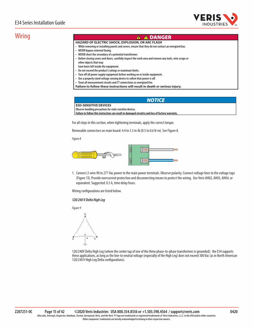
HAZARD OF ELECTRIC SHOCK, EXPLOSION, OR ARC FLASH• While removing or installing panels and covers, ensure that they do not contact an energized bus.• NEVER bypass external fusing.• NEVER short the secondary of a potential transformer.• Before closing covers and doors, carefully inspect the work area and remove any tools, wire scraps or
other objects that may have been left inside the equipment. • Do not exceed the product’s ratings or maximum limits.• Turn off all power supply equipment before working on or inside equipment.• Use a properly rated voltage sensing device to cofirm that power is off.• Treat all measurement circuits and CT connections as energized live.Failure to follow these instructions will result in death or serious injury.
DANGER
ESD-SENSITIVE DEVICESObserve handling precautions for static sensitive devices.Failure to follow this instruction can result in damaged circuitry and loss of factory warranty.
NOTICE
For all steps in this section, when tightening terminals, apply the correct torque.
Removable connectors on main board: 4.4 to 5.3 in-lb (0.5 to 0.6 N-m). See Figure 8.
Figure 8
1. Connect 2-wire 90 to 277 Vac power to the main power terminals. Observe polarity. Connect voltage lines to the voltage taps (Figure 13). Provide overcurrent protection and disconnecting means to protect the wiring. Use Veris AH02, AH03, AH04, or equivalent. Suggested: 0.5 A, time delay fuses.
Wiring configurations are listed below.
120/240 V Delta High Leg
Figure 9
V3
V2 V1
NN
120/240V Delta High Leg (where the center tap of one of the three phase-to-phase transformers is grounded): the E34 supports these applications, as long as the line-to neutral voltage (especially of the High Leg) does not exceed 300 Vac (as in North American 120/240 V High Leg Delta configurations).
Wiring

Z207251-0C Page 16 of 42 ©2020 Veris Industries USA 800.354.8556 or +1.503.598.4564 / [email protected] 0420 Alta Labs, Enercept, Enspector, Hawkeye, Trustat, Aerospond, Veris, and the Veris ‘V’ logo are trademarks or registered trademarks of Veris Industries, L.L.C. in the USA and/or other countries.
Other companies’ trademarks are hereby acknowledged to belong to their respective owners.
E34 Series Installation GuideTM
Wiring (cont.) 3-Wire (Ungrounded) Delta
Figure 10
V3
XV2 V1
In 3-wire (ungrounded) Delta applications, the E34 supports these applications with the following caveats:
Control Power for the meter cannot exceed 277 Vac. In applications where the L-L voltage is 277 Vac or less (e.g. 208 V line-to-line) it can be connected to two of the phases being monitored without exceeding the limit. For higher voltages (e.g. 480 V line-to-line), this must be supplied from a source that is 277 Vac or less. It could be a separate source or a transformer can be used to step it down from two of the phases being measured.
4-Wire Wye, 3-Wire Split-Phase and 2-Wire Single Phase
Figure 11
4-wireWye
3-wireSplit-phase
2-wireSingle-phase
V3
V2 V1
V2
V1
V1
NN
N
The E34 supports measurement of all 4-wire Wye, 3-wire split-phase and 2-wire single phase and configurations that operate between 90 and 300 Vac line-to neutral. Voltage taps are shared by both panels.
Corner-Grounded Delta
Figure 12
V3
V2 V1
Corner-grounded delta: the E34 does not support these applications at any voltage level.
The E34 supports measurement of all 4-wire Wye, 3-wire split-phase and 2-wire single phase and configurations that operate between 90 and 300 Vac line-to neutral. Voltage taps are shared by both panels.

Z207251-0C Page 17 of 42 ©2020 Veris Industries USA 800.354.8556 or +1.503.598.4564 / [email protected] 0420 Alta Labs, Enercept, Enspector, Hawkeye, Trustat, Aerospond, Veris, and the Veris ‘V’ logo are trademarks or registered trademarks of Veris Industries, L.L.C. in the USA and/or other countries.
Other companies’ trademarks are hereby acknowledged to belong to their respective owners.
E34 Series Installation GuideTM
Figure 13
1. Connect 2-wire or 4-wire Modbus RS-485 daisy chain network (Figures 14 and 15).
Figure 14
L-N
N V3 V2 V1 V1 V2/N
V1 V2/NL-L
Voltage Inputs90 to 300 V 50/60 Hz
Control Power100 to 277 V 50/60 Hz 15 VA
L-L
V2/N
V1/L
V1 V2 V3 N
L-N
Voltage Inputs90 to 300 V 50/60 Hz
ControlPower
90 to 277 Vac
E34A
E34E
E34A
E34E
RS-485S–+
S–+SHIELD
RX- TX-
RX+ TX+
TX-
TX+

Z207251-0C Page 18 of 42 ©2020 Veris Industries USA 800.354.8556 or +1.503.598.4564 / [email protected] 0420 Alta Labs, Enercept, Enspector, Hawkeye, Trustat, Aerospond, Veris, and the Veris ‘V’ logo are trademarks or registered trademarks of Veris Industries, L.L.C. in the USA and/or other countries.
Other companies’ trademarks are hereby acknowledged to belong to their respective owners.
E34 Series Installation GuideTM
Wiring (cont.) Figure 15
SHLDTX+ TX+
RX+TX–TX-
RX-
SHIELD SHIELD
2. Mechanically secure the RS-485 cable(s) where they enter the electrical panel.
3. Connect all RS-485 devices in a daisy-chain fashion, and properly terminate the chain (Figure 16).
120 Ω terminator at each end of daisy chain
120 Ω terminator at each end of daisy chainRS-485 cable RS-485 cable
–+
Figure 16
4. Shield the RS-485 cable using twisted-pair wire. The cable must be voltage-rated for the installation.
HAZARD OF ELECTRIC SHOCK, EXPLOSION, OR ARC FLASH• Turn off all power supplying equipment before working on or inside the equipment.• Use a properly rated voltage sensing device to confirm that power is off.Failure to follow these instructions will result in death or serious injury.
DANGER
ESD-SENSITIVE DEVICESObserve handling precautions for static sensitive devices.Failure to follow this instruction can result in damaged circuitry and loss of factory warranty.
NOTICE
1. Communications Configuration: Communications parameters for the E34 series are field selectable for your convenience. Please see the Product Diagrams section for selector location. E34A models are set using DIP switches on the main board. E34E models are configured with the GUI (Graphical User Interface). See the Gateway Configuration section for further information. The following parameters are configurable:
• Baud Rate: 9600, 19200, 38400• Parity On or Off• Parity: Odd or Even• Wiring: 2 or 4
Configuration
E34A Models E34E Models
Z207251-0C Page 19 of 42 ©2020 Veris Industries USA 800.354.8556 or +1.503.598.4564 / [email protected] 0420 Alta Labs, Enercept, Enspector, Hawkeye, Trustat, Aerospond, Veris, and the Veris ‘V’ logo are trademarks or registered trademarks of Veris Industries, L.L.C. in the USA and/or other countries.
Other companies’ trademarks are hereby acknowledged to belong to their respective owners.
E34 Series Installation GuideTM
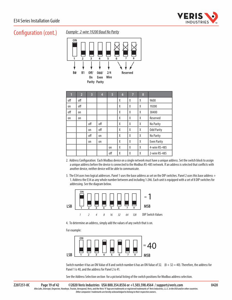
Example: 2-wire 19200 Baud No Parity
Bø ReservedB1 Off/On
Parity
2/4Wire
Odd/Even
Parity
1 2 3 4 5 6 7 8
off off X X X 9600
on off X X X 19200
off on X X X 38400
on on X X X Reserved
off off X X X No Parity
on off X X X Odd Parity
off on X X X No Parity
on on X X X Even Parity
on X X X 4-wire RS-485
off X X X 2-wire RS-485
2. Address Configuration: Each Modbus device on a single network must have a unique address. Set the switch block to assign a unique address before the device is connected to the Modbus RS-485 network. If an address is selected that conflicts with another device, neither device will be able to communicate.
3. The E34 uses two logical addresses. Panel 1 uses the base address as set on the DIP switches. Panel 2 uses this base address + 1. Address the E34 as any whole number between and including 1-246. Each unit is equipped with a set of 8 DIP switches for addressing. See the diagram below.
1LSB MSB
1 2 4 8 16 32 64 128 DIP Switch Values
=
4. To determine an address, simply add the values of any switch that is on.
For example:
40=
LSB MSB
Switch number 4 has an ON Value of 8 and switch number 6 has an ON Value of 32. (8 + 32 = 40). Therefore, the address for Panel 1 is 40, and the address for Panel 2 is 41.
See the Address Selection section for a pictorial listing of the switch positions for Modbus address selection.
Configuration (cont.)

Z207251-0C Page 20 of 42 ©2020 Veris Industries USA 800.354.8556 or +1.503.598.4564 / [email protected] 0420 Alta Labs, Enercept, Enspector, Hawkeye, Trustat, Aerospond, Veris, and the Veris ‘V’ logo are trademarks or registered trademarks of Veris Industries, L.L.C. in the USA and/or other countries.
Other companies’ trademarks are hereby acknowledged to belong to their respective owners.
E34 Series Installation GuideTM
The E34A includes two DIP switches, as shown below. Switches are shown in their default positions.
Comms Address Comms Settings
E34A
Default DIP Switch Settings

Z207251-0C Page 21 of 42 ©2020 Veris Industries USA 800.354.8556 or +1.503.598.4564 / [email protected] 0420 Alta Labs, Enercept, Enspector, Hawkeye, Trustat, Aerospond, Veris, and the Veris ‘V’ logo are trademarks or registered trademarks of Veris Industries, L.L.C. in the USA and/or other countries.
Other companies’ trademarks are hereby acknowledged to belong to their respective owners.
E34 Series Installation GuideTM
DO NOTUSE ZERO
1 2 3 4 5 6 7 8 9 10
11 12 13 14 15 16 17 18 19 20 21
22 23 24 25 26 27 28 29 30 31 32
33 34 35 36 37 38 39 40 41 42 43
44 45 46 47 48 49 50 51 52 53 54
55 56 57 58 59 60 61 62 63 246 ......
Address Selection
Z207251-0C Page 22 of 42 ©2020 Veris Industries USA 800.354.8556 or +1.503.598.4564 / [email protected] 0420 Alta Labs, Enercept, Enspector, Hawkeye, Trustat, Aerospond, Veris, and the Veris ‘V’ logo are trademarks or registered trademarks of Veris Industries, L.L.C. in the USA and/or other countries.
Other companies’ trademarks are hereby acknowledged to belong to their respective owners.
E34 Series Installation GuideTM
Gateway Configuration
A quali�ed person is one who has skills and knowledgerelated to the construction and operation of this electricalequipment and installations, and has received safety trainingto recognize and avoid the hazards involved. NEC Article 100If this product is used in a manner not speci�ed by themanufacturer, the protection provided by the product may beimpaired. No responsibility is assumed by the manufacturer for any consequences arising out of the use of this material.
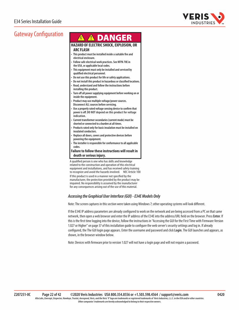
DANGERHAZARD OF ELECTRIC SHOCK, EXPLOSION, OR
ARC FLASH• This product must be installed inside a suitable fire and
electrical enclosure.• Follow safe electrical work practices. See NFPA 70E in
the USA, or applicable local codes.• This equipment must only be installed and serviced by
qualified electrical personnel.• Do not use this product for life or safety applications.• Do not install this product in hazardous or classified locations.• Read, understand and follow the instructions before
installing this product.• Turn off all power supplying equipment before working on or
inside the equipment.• Product may use multiple voltage/power sources. Disconnect ALL sources before servicing.• Use a properly rated voltage sensing device to confirm that
power is off. DO NOT depend on this product for voltage indication.
• Current transformer secondaries (current mode) must be shorted or connected to a burden at all times.
• Products rated only for basic insulation must be installed on insulated conductors.
• Replace all doors, covers and protective devices before powering the equipment.
• The installer is responsible for conformance to all applicable codes.
Failure to follow these instructions will result in death or serious injury.
Accessing the Graphical User Interface (GUI) - E34E Models Only
Note: The screen captures in this section were taken using Windows 7; other operating systems will look different.
If the E34E IP address parameters are already configured to work on the network and are being accessed from a PC on that same network, then open a web browser and enter the IP address of the E34E into the address/URL field on the browser. Press Enter. If this is the first time logging into the device, follow the instructions in “Accessing the GUI for the First Time with Firmware Version 1.027 or Higher” on page 37 of this installation guide to configure the web server’s security settings and log in. If already configured, the The GUI login page appears. Enter the username and password and click Login. The GUI launches and appears, as shown, in the browser window below.
Note: Devices with firmware prior to version 1.027 will not have a login page and will not require a password.

Z207251-0C Page 23 of 42 ©2020 Veris Industries USA 800.354.8556 or +1.503.598.4564 / [email protected] 0420 Alta Labs, Enercept, Enspector, Hawkeye, Trustat, Aerospond, Veris, and the Veris ‘V’ logo are trademarks or registered trademarks of Veris Industries, L.L.C. in the USA and/or other countries.
Other companies’ trademarks are hereby acknowledged to belong to their respective owners.
E34 Series Installation GuideTM
If the E34E IP address parameters are not configured for the network, connect a PC directly and access the GUI from it as follows:
1. Connect a standard Ethernet cable between a PC and the E34E if they are not already connected. Secure a ferrite filter (included) around the Ethernet cable to ensure the device meets emission requirements.
E34E
2. Temporarily change the IP address of the PC to a static value on the same subnet as the E34E. For example: If the E34E is set to its factory default IP address of 192.168.1.24, set the PC to an unused static IP address on the 192.168.1.xxx subnet (where xxx is any value between 1 and 255, except 24). Set the subnet mask to 255.255.255.0.
a. Open the Control Panel:
b. In the Control Panel, select Network and Sharing Center. In the Sharing Center, select Change Adapter Settings in the list at the upper left corner.
c. Select the connection for the network to which the E34E is connected.
Gateway Configuration (cont.)

Z207251-0C Page 24 of 42 ©2020 Veris Industries USA 800.354.8556 or +1.503.598.4564 / [email protected] 0420 Alta Labs, Enercept, Enspector, Hawkeye, Trustat, Aerospond, Veris, and the Veris ‘V’ logo are trademarks or registered trademarks of Veris Industries, L.L.C. in the USA and/or other countries.
Other companies’ trademarks are hereby acknowledged to belong to their respective owners.
E34 Series Installation GuideTM
When the Local Area Connection Status dialog box appears, click Properties.
d. Highlight Internet Protocol Version 4 (TCP/IPv4), and click OK.
Gateway Configuration (cont.)
Z207251-0C Page 25 of 42 ©2020 Veris Industries USA 800.354.8556 or +1.503.598.4564 / [email protected] 0420 Alta Labs, Enercept, Enspector, Hawkeye, Trustat, Aerospond, Veris, and the Veris ‘V’ logo are trademarks or registered trademarks of Veris Industries, L.L.C. in the USA and/or other countries.
Other companies’ trademarks are hereby acknowledged to belong to their respective owners.
E34 Series Installation GuideTM
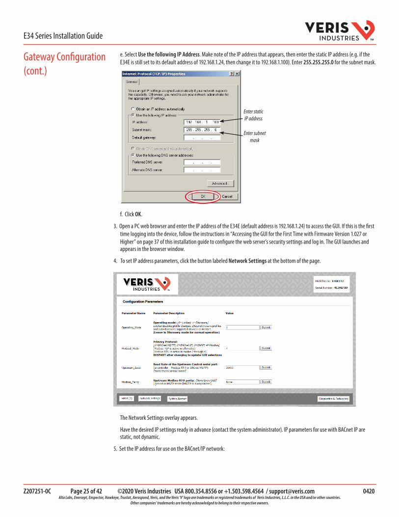
e. Select Use the following IP Address. Make note of the IP address that appears, then enter the static IP address (e.g. if the E34E is still set to its default address of 192.168.1.24, then change it to 192.168.1.100). Enter 255.255.255.0 for the subnet mask.
Enter static IP address
Enter subnet mask
f. Click OK.
3. Open a PC web browser and enter the IP address of the E34E (default address is 192.168.1.24) to access the GUI. If this is the first time logging into the device, follow the instructions in “Accessing the GUI for the First Time with Firmware Version 1.027 or Higher” on page 37 of this installation guide to configure the web server’s security settings and log in. The GUI launches and appears in the browser window.
4. To set IP address parameters, click the button labeled Network Settings at the bottom of the page.
The Network Settings overlay appears.
Have the desired IP settings ready in advance (contact the system administrator). IP parameters for use with BACnet IP are static, not dynamic.
5. Set the IP address for use on the BACnet/IP network:
Gateway Configuration (cont.)

Z207251-0C Page 26 of 42 ©2020 Veris Industries USA 800.354.8556 or +1.503.598.4564 / [email protected] 0420 Alta Labs, Enercept, Enspector, Hawkeye, Trustat, Aerospond, Veris, and the Veris ‘V’ logo are trademarks or registered trademarks of Veris Industries, L.L.C. in the USA and/or other countries.
Other companies’ trademarks are hereby acknowledged to belong to their respective owners.
E34 Series Installation GuideTM
a. Enter the desired IP address in the N1_IP_Address field (in the format xxx.xxx.xxx.xxx)
b. If necessary, change the Subnet Mask by entering the appropriate new value in the N1_Netmask field
c. If the E34E is connected to an Ethernet gateway, enter its IP address in the Default Gateway field. This is important when the E34E is used as a BACnet BBMD device.
d. Click the Update IP Settings button. The E34E changes its settings.
e. Click the System Restart button and wait for the E34E to fully initialize. The GUI will connect when the E34E is installed on a network that matches the settings and the new IP address is entered into a web browser on a PC properly configured for the network.
Using the GUI to Set the Configuration Parameters for the Communication Protocols
Access the GUI according the instructions in the Accessing the Graphical User Interface (GUI) section.
The home screen on the GUI provides fields for configuration of the E34E. The E34E has four primary modes of operation, each of which support a different combination of protocols. Each option field has a Submit button to the right. When changing the value in any field, click Submit to store the new value. The GUI prompts the user to restart the system. If multiple values are changed,
Gateway Configuration (cont.)

Z207251-0C Page 27 of 42 ©2020 Veris Industries USA 800.354.8556 or +1.503.598.4564 / [email protected] 0420 Alta Labs, Enercept, Enspector, Hawkeye, Trustat, Aerospond, Veris, and the Veris ‘V’ logo are trademarks or registered trademarks of Veris Industries, L.L.C. in the USA and/or other countries.
Other companies’ trademarks are hereby acknowledged to belong to their respective owners.
E34 Series Installation GuideTM
it is easiest to submit all changes and restart only once when finished with the whole screen. To restart, click the System Restart button in the row at the bottom of the screen. The restart takes several seconds, during which the server may lose its connection. Messages appear at the top of the screen indicating current status, but do not perform any actions. Simply allow the tool to complete the restart cycle.
The first selection in the GUI is Operating_Mode, which has two choices:
1. Locked: used for all normal product operation. It is provided as a tool for high-level technical support. The gateway retains its current profile configuration when powered. 2. Discovery mode (default): deletes profiles and rediscovers them when the device is powered again. The results are the same, unless the profile configuration is intentionally altered. Profile selection and discovery are especially important when using BACnet or SNMP protocols. For normal operation, always use discovery mode.
The second selection in the GUI is Protocol_Mode, used to select the combination of protocols the product communicates with. The E34E supports five protocols, some of which can operate simultaneously. The table below shows which protocols are supported in each mode.
Protocol Mode Primary Protocol Ethernet Protocol RS-485 Protocol
1 BACnet MS/TP Modbus TCP BACnet MS/TP
2 BACnet IP BACnet IP/Modbus TCP Modbus RTU
3 SNMP SNMP/Modbus TCP Modbus RTU
4 Modbus Modbus TCP Modbus RTU To select a primary protocol mode, enter the corresponding number into the text field adjacent to the Primary Protocol option and click the Submit button to the right of the text field. A prompt appears at the top of the screen instructing the user to restart the system. When finished, the screen refreshes itself with the appropriate fields for the selected mode.
The next GUI selection, in any protocol mode, is the Upstream_Baud rate selection. If you have selected BACnet MS/TP (mode 1) as the primary protocol mode, this value sets the MS/TP baud rate. If you have selected modes 2 or 3 as the primary protocol mode, you may not be using the RS-485 interface at all. If so, this setting can be ignored.
If you have selected BACnet IP, SNMP or Modbus mode, the next selection is Modbus_Address, which sets the Modbus address(es) for the E34E when access with Modbus RTU with the RS-485 serial connection.
The next selection (in BACnet IP, SNMP or Modbus modes) is Modbus_Parity, which sets the parity of the upstream serial connection. If using Modbus RTU protocol, set this to match your Modbus master. If not, ignore this field.
The following sections show the field selections (with factory default values) specific to each of the four Protocol_Modes.
Gateway Configuration (cont.)

Z207251-0C Page 28 of 42 ©2020 Veris Industries USA 800.354.8556 or +1.503.598.4564 / [email protected] 0420 Alta Labs, Enercept, Enspector, Hawkeye, Trustat, Aerospond, Veris, and the Veris ‘V’ logo are trademarks or registered trademarks of Veris Industries, L.L.C. in the USA and/or other countries.
Other companies’ trademarks are hereby acknowledged to belong to their respective owners.
E34 Series Installation GuideTM
1. BACnet MS/TP mode
The first three options are discussed previously.
The DeviceID_Offset parameter is used to assign Device_IDs on power-up or on restart until they have been overwritten via BACnet. Enter your desired value here and click Submit. The new value is first used at the next power-up or system restart. Valid Device_ID numbers range from 1 to 4194303. Since the numbers assigned during discovery are the sum of the Offset and the Modbus address (which can be any value from 1 to 247), the Offset values entered in the GUI must be no larger than 4194057.
The E34E gateway creates a BACnet virtual router and separate BACnet devices for each 42-channel meter panel behind this virtual router, allowing the devices to be discoverable and independently accessed via BACnet, even if the virtual router is connected by MS/TP, using a single MAC address. To use this product with MS/TP, the BACnet system must support the discovery and use of a BACnet router on the MS/TP trunk and any devices beyond it. This virtual router creates an exclusive BACnet network on which the meter’s BACnet devices reside. This network must have a BACnet network number that is different from any other networks in the entire BACnet enterprise. When multiple E34E products are added anywhere in the enterprise, each one must have a unique network number. If an exclusive value in this field is not set, communication conflicts in the BACnet system may occur.
Enter a non-conflicting value here and click Submit. Valid network numbers range from 1 to 65534; if other values are entered, the network number defaults to 5. The new value is first used at the next power-up or system restart. If using an external BACnet router to connect the E34E as an MS/TP device, it is recommended that the router also be restarted after the E34E has completed discovery, when the network number is changed.
The next field for the BACnet MS/TP protocol mode is the MSTP_Max_Master, which allows this value to be set prior to using BACnet software to access the E34E. The default value of 127 works regardless of the addresses the MS/TP network uses, but selecting a lower value may optimize the network. Do not set this value lower than the highest address on the network. To set this
Gateway Configuration (cont.)

Z207251-0C Page 29 of 42 ©2020 Veris Industries USA 800.354.8556 or +1.503.598.4564 / [email protected] 0420 Alta Labs, Enercept, Enspector, Hawkeye, Trustat, Aerospond, Veris, and the Veris ‘V’ logo are trademarks or registered trademarks of Veris Industries, L.L.C. in the USA and/or other countries.
Other companies’ trademarks are hereby acknowledged to belong to their respective owners.
E34 Series Installation GuideTM
value via BACnet, write to the Max_Master property of the device object for the E34E’s virtual router.
The next field for the BACnet MS/TP protocol mode is the MSTP_MAC_Addr, which sets the MAC address for the virtual router. The E34E panel(s) are devices on the internal BACnet network and are not directly addressable as MAC addresses on the MS/TP network.
The final field for the BACnet MS/TP mode is RTC_Control, which selects which protocol (BACnet or Modbus) has write access to the RTC. If 0 (BACnet) is selected, the RTC is set using the BACnet Time Synchronization service. If 1 (Modbus) is selected, the RTC is set by writing to the appropriate Modbus registers.
2. BACnet IP mode
BACnet IP mode uses the same DeviceID_Offset, Virt_Router_Net and RTC_Control parameters described above for BACnet MS/TP mode. One additional parameter, BACnet_IP_Port, is used to set the UDP port. Most BACnet systems use the default port (47808 decimal, 0xBAC0 hex) that is recommended in the BACnet standard as the only UDP port. Some large systems need to segment the enterprise and use more than port. If so, enter the number of the port you need to use to access this device. BACnet IP mode does not use MSTP_Max_Master or MSTP_MAC_Addr.
Gateway Configuration (cont.)
Z207251-0C Page 30 of 42 ©2020 Veris Industries USA 800.354.8556 or +1.503.598.4564 / [email protected] 0420 Alta Labs, Enercept, Enspector, Hawkeye, Trustat, Aerospond, Veris, and the Veris ‘V’ logo are trademarks or registered trademarks of Veris Industries, L.L.C. in the USA and/or other countries.
Other companies’ trademarks are hereby acknowledged to belong to their respective owners.
E34 Series Installation GuideTM
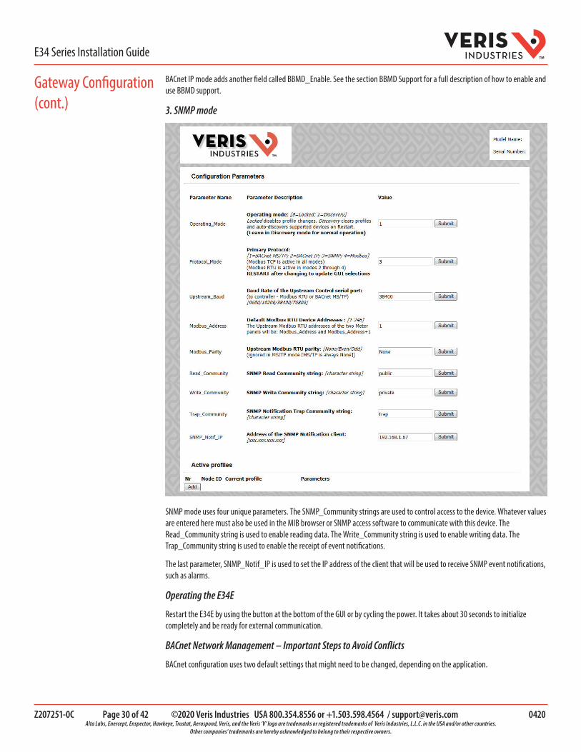
BACnet IP mode adds another field called BBMD_Enable. See the section BBMD Support for a full description of how to enable and use BBMD support.
3. SNMP mode
SNMP mode uses four unique parameters. The SNMP_Community strings are used to control access to the device. Whatever values are entered here must also be used in the MIB browser or SNMP access software to communicate with this device. The Read_Community string is used to enable reading data. The Write_Community string is used to enable writing data. The Trap_Community string is used to enable the receipt of event notifications.
The last parameter, SNMP_Notif_IP is used to set the IP address of the client that will be used to receive SNMP event notifications, such as alarms.
Operating the E34E
Restart the E34E by using the button at the bottom of the GUI or by cycling the power. It takes about 30 seconds to initialize completely and be ready for external communication.
BACnet Network Management – Important Steps to Avoid Conflicts
BACnet configuration uses two default settings that might need to be changed, depending on the application.
Gateway Configuration (cont.)

Z207251-0C Page 31 of 42 ©2020 Veris Industries USA 800.354.8556 or +1.503.598.4564 / [email protected] 0420 Alta Labs, Enercept, Enspector, Hawkeye, Trustat, Aerospond, Veris, and the Veris ‘V’ logo are trademarks or registered trademarks of Veris Industries, L.L.C. in the USA and/or other countries.
Other companies’ trademarks are hereby acknowledged to belong to their respective owners.
E34 Series Installation GuideTM
a. Virtual router network ID number. Every logical network segment (IP subnet, MS/TP trunk, etc.) in an entire system must have a (16-bit) network ID number that is unique from all other BACnet networks in the enterprise. The BACnet network administrator assigns this network ID so that no two ID numbers conflict (whether using BACnet/IP or MS/TP). Within each segment, every device is physically identified by the combination of its 8-bit MAC address and the 16-bit network ID number.
To support multiple meter panels (Panel 1 and Panel 2 are separate) with a single gateway, the E34E creates a virtual BACnet router that presents multiple BACnet devices using a single (its own) MS/TP MAC address. Each E34E must have its own (internal) network ID, and it creates a device object for itself and one for each Modbus address discovered.
The factory default network address is 50 (decimal). If that number is already in use in the system, assign a unique address using the graphical user interface (GUI) on the built-in web server (this requires an Ethernet connection to a web browser; see BACnet/IP Setup section for instructions on changing configuration settings using the GUI). Valid network numbers range from 1 to 65534; if other values are entered, the network number defaults to 5.
b. Device_ID Offset. Every BACnet device must have a BACnet Device_ID number that is unique throughout the entire enterprise. Since the E34E presents every Modbus meter as a BACnet device, each connected meter that has a Modbus address must have a BACnet Device_ID.
By default, each device discovered receives a Device_ID number that is the sum of an offset value (default is 50000) and the Modbus address of the device. If these Device_ID numbers cause a conflict with existing devices in the system, or if the system includes multiple E34 Series, change the Device_ID numbers before connecting the E34E to the system. This can be managed one of two ways:
i. Connect to the E34E directly (offline from the system) with the devices (meters). After the E34E discovers the devices and assigns their default ID numbers, the user can choose new Device_ID values and write these to each device using BACnet software. Subsequent discoveries will not overwrite these values with defaults even if the E34E is then set to Discovery mode.
ii. Use the GUI on the built-in web server to modify the offset value used to calculate default Device_IDs in the discovery process (this requires an Ethernet connection to a web browser; see BACnet/IP Setup section for instructions on changing configuration settings using the GUI). The E34E retains this offset value and uses it to assign Device_ID numbers every time power is cycled if the E34E is in Discovery mode. Valid Device_ID numbers range from 1 to 4194303. Since the numbers assigned during discovery are the sum of the Offset and the Modbus address (which can be any value from 1 to 247), any Offset values entered in the GUI must be less than 4194057.
Gateway Configuration (cont.)

Z207251-0C Page 32 of 42 ©2020 Veris Industries USA 800.354.8556 or +1.503.598.4564 / [email protected] 0420 Alta Labs, Enercept, Enspector, Hawkeye, Trustat, Aerospond, Veris, and the Veris ‘V’ logo are trademarks or registered trademarks of Veris Industries, L.L.C. in the USA and/or other countries.
Other companies’ trademarks are hereby acknowledged to belong to their respective owners.
E34 Series Installation GuideTM
BACnet PICS (Protocol Implementation Conformance Statement)
Vendor Name: Veris IndustriesBACnet Vendor ID 133Product Name: E34E Series Multi-Circuit MeterProduct Model Number: <Model Number>Product Description: Multi-Circuit MeterMulti-Circuit Meter BACnet Protocol Version: Version 1 Revision 12
BACnet Standardized Device Profile (Annex L) – [Note: E34E incorporates a gateway device]• BACnet Application Specific Controller (B-ASC)
BACnet Interoperability Building Blocks Supported (Annex K):• K.1.2 BIBB - Data Sharing - ReadProperty-B (DS-RP-B)• K.1.4 BIBB - Data Sharing - ReadPropertyMultiple-B (DS-RPM-B)• K.1.8 BIBB - Data Sharing - WriteProperty-B (DS-WP-B)• K.1.10 BIBB - Data Sharing - WritePropertyMultiple-B (DS-WPM-B)• K.1.12 BIBB - Data Sharing - COV-B (DS-COV-B)• K.2.2 BIBB - Alarm and Event - Notification Internal-B (AE-N-I-B)• K.2.5 BIBB - Alarm and Event - ACK-B (AE-ACK-B)• K.2.11 BIBB - Alarm and Event - Information-B (AE-INFO-B)• K.5.2 BIBB - Device Management - Dynamic Device Binding-B (DM-DDB-B)• K.5.4 BIBB - Device Management - Dynamic Object Binding-B (DM-DOB-B)• K.5.6 BIBB - Device Management - DeviceCommunicationControl-B (DM-DCC-B)• K.5.12 BIBB - Device Management - TimeSyncronization-B (DM-TS-B)• K.5.22 BIBB - Device Management - List Manipulation-B (DM-LM-B)
Standard Object Types Supported• Device Object• Analog Input• Analog Output• Analog Value
Unsupported Properties and Restrictions• Does not support BACnet CreateObject• Does not support BACnet DeleteObject• Does not support any proprietary properties• No proprietary properties exist• No range restrictions exist• Max_Master is writable
Data Link Layer Options:• BACnet IP, (Annex J)• MS/TP master (Clause 9), baud rate up to 76.8 kbps
Networking Options: • BACnet/IP Broadcast Management Device (BBMD)• Registrations by Foreign Devices
Character Sets Supported: • ISO 10646 (UTF-8) / ANSI X3.4
BACnet PICS

Z207251-0C Page 33 of 42 ©2020 Veris Industries USA 800.354.8556 or +1.503.598.4564 / [email protected] 0420 Alta Labs, Enercept, Enspector, Hawkeye, Trustat, Aerospond, Veris, and the Veris ‘V’ logo are trademarks or registered trademarks of Veris Industries, L.L.C. in the USA and/or other countries.
Other companies’ trademarks are hereby acknowledged to belong to their respective owners.
E34 Series Installation GuideTM
The E34E consists of a BACnet virtual router and one or two 42-channel branch circuit meters. The BACnet virtual router has its own device object and an internal BACnet network. The branch circuit monitors have their own device objects that are logical devices on the network internal to (beneath) the virtual router. It is critical that the network number of the virtual router’s internal network be different than any other network number in your entire BACnet system. The network number is set to 50 at the factory, but can be changed in the GUI or by writing to the Present_Value of the AV2 data object associated with that device. Changes to the network number do not take effect until the E34E is re-started, either from the GUI or by cycling the power.
The default Device ID of the virtual router is the Device_Offset parameter, which is set to 5000 at the factory, but can be changed in the GUI or by writing to Present_Value of the AV1 data object associated with that device. Changes to the network number do not take affect until the E34E is re-started, either from the GUI or by cycling the power. The default Device IDs are numbered to consecutively follow the Device ID of the virtual router (e.g. if the Device_Offset parameter is 50000, the virtual router has a Device_ID of 50000, the branch circuit monitor called Panel 1 has a Device_ID of 50001 and the branch circuit monitor called Panel 2 (if present) has a Device_ID of 50002.
All Device_IDs are writable. Once a device’s Object_Identifier is overwritten, changes to the ID Offset no longer affect that Object_Identifier, even in Discovery mode. Make further changes to the value by writing the Object_Identifier property.
The default Object_Name property value of each device object is an abbreviated name of the meter series discovered with an underscore and the Modbus address of the meter appended to it. The Object_Name is a writable property. Once a device’s Object_Name is overwritten, the Object_Name does not revert to the initial default, even in Discovery mode. Make further changes to the value by writing the Object_name property.
The E34E supports Subscribe_COV, with default COV increment values assigned as shown in the data object tables. If these values are not appropriate for a specific application, write them as needed when they are subscribed. On subsequent power cycles, no subscriptions are active and the COV increments return to their default values.
With few exceptions, any data values written to AV objects are accepted (without error) by the data object and passed through to the corresponding Modbus register. There is no direct indication via the BACnet protocol if invalid values are rejected. After an invalid value is written to the Present_Value of an AV, subsequent reads of that property return the new (invalid) value until the next time the E34E refreshes its data (this may take several seconds).
BBMD Support
When the E34E is in BACnet IP mode, it can be configured as a BACnet Broadcast Management Device (BBMD) by entering “BBMD” in the Enable BBMD Support field in the GUI, adding devices to a comma separated value text file named bdt.ini, and loading it onto the device. The example below shows the syntax required for the bdt.ini file. All lines beginning with two forward slashes are interpreted as comments. Use exactly one line per device added, separated by commas (no spaces). The file must include an entry (line) for each BBMD device in the BACnet enterprise, including the E34E itself. Note: The default gateway address in the network setup must be correct for BBMD support to operate correctly. Once edited, upload the btd.ini file to the gateway through the GUI. Click the Diagnostics and Debugging button in the lower right corner of the GUI and follow the folder tree under Navigation to the following folder: Veris E3x Series Gateway/Setup/File Transfer. Select the General tab (this is important - using the wrong tab can overwrite critical files). Click the Browse button and select your bdt.ini file. Then click Submit. The GUI quickly indicates “The file was updated successfully.” Click the System Restart button, click OK on the confirmation dialog and wait for the gateway to reinitialize (takes about 30 seconds). BBMD changes are made by uploading a new btd.ini file. After setting the GUI to enable BBMD support and transferring a new or revised bdt.ini file, restart the E34E to load the file. BBMD support can be disabled in the GUI by entering “-” (a hyphen) in the Enable BBMD Support field in the GUI.
// Bdt.ini// The format of this table must be (without the forward slashes - they are comment indicators):////BBMD IP_Address , BBMD port , BBMD subnet Mask//147.26.116.217,47808,255.255.255.255172.16.17.198,47808,255.255.255.255
General BACnet Programming Information

Z207251-0C Page 34 of 42 ©2020 Veris Industries USA 800.354.8556 or +1.503.598.4564 / [email protected] 0420 Alta Labs, Enercept, Enspector, Hawkeye, Trustat, Aerospond, Veris, and the Veris ‘V’ logo are trademarks or registered trademarks of Veris Industries, L.L.C. in the USA and/or other countries.
Other companies’ trademarks are hereby acknowledged to belong to their respective owners.
E34 Series Installation GuideTM
General SNMP Programming Information
The E34E can be configured to support the SNMP V2c protocol over Ethernet. The SNMP community string and the IP address for the client receiving SNMP V2c event notifications can be set via the GUI. MIB files are available for download at www.veris.com/SNMP.aspx to enable accessing the E34E from an MIB browser.
The E34E OID structure organizes the data under two “panels” representing the two breaker panels that can be monitored by a fully populated E34E. Panel 1 corresponds to the branch current sensor strips connected to the “Panel 1A” and “Panel 1B” connectors and to the data set under Modbus address 1 or BACnet device identified as Node_1 in the GUI. Panel 2 corresponds to the branch current sensor strips connected to the “Panel 2A” and “Panel 2B” connectors and to the data set under Modbus address 2 or BACnet device identified as Node_2 in the GUI.
For each panel, data is arranged under six tree branches.
• The Configuration branch contains all writable configuration parameters. • The Alarms branch contains all the alarm notification traps, the global alarm status registers and counters and tables
of the alarm status indicators.• The Voltage Inputs branch contains all data measurements pertaining to the voltage inputs.• The Auxiliary Inputs branch contains all data measurements pertaining to the aux inputs other than voltage-related.• The Branch Inputs branch contains all data measurements to the branch inputs in table format.• The Flex Circuits branch contains all data measurements to the logical meter summaries in table format.
1. Reconnect power to the panel.
2. Configure installation mode using Modbus Register 6.
3. Configure CT scaling.
4. Configure alarms.
5. Configure demand.
Download the free NetConfig configuration tool and the E3x Commissioning Guide from www.veris.com/modbus to commission the device for operation.
CommissioningHAZARD OF ELECTRIC SHOCK, EXPLOSION, OR ARC FLASH• Follow safe electrical work practices. See NFPA 70E in the USA, or applicable local codes.• Replace all doors, covers and protective devices before powering the equipment.Failure to follow these instructions will result in death or serious injury.
DANGER

Z207251-0C Page 35 of 42 ©2020 Veris Industries USA 800.354.8556 or +1.503.598.4564 / [email protected] 0420 Alta Labs, Enercept, Enspector, Hawkeye, Trustat, Aerospond, Veris, and the Veris ‘V’ logo are trademarks or registered trademarks of Veris Industries, L.L.C. in the USA and/or other countries.
Other companies’ trademarks are hereby acknowledged to belong to their respective owners.
E34 Series Installation GuideTM
Overview
This chapter contains up-to-date information about your product’s cybersecurity. Network administrators, system integrators and personnel that commission, maintain or dispose of a device should:
• Apply and maintain the device’s security capabilities. See “Device security capabilities” for more details.• Review assumptions about protected environments. See “Protected environment assumptions” for more details.• Address potential risks and mitigation strategies. See “Potential Risks and compensating controls” for more details.• Follow recommendations to optimize cybersecurity.
Your device has security capabilities that:
• Allow it to be part of a NERC CIP compliant facility. Go to the North American Electric Reliability Corporation website for information on NERC Reliability Standards.
• Align with cybersecurity standards in the IEC 62443 international standard for business IT systems and Industrial Automation and Control Systems (IACS) products. Go to the International Electrotechnical Commission website for information about the IEC 62443 international standard.
WARNINGPOTENTIAL COMPROMISE OF SYSTEM AVAILABILITY, INTEGRITY, AND CONFIDENTIALITY•
•
•
•
Change default passwords to help prevent unauthorized access to device settings and information.Disable unused ports/services and default accounts, where possible, to minimize pathways for malicious attacks.Place networked devices behind multiple layers of cyber defenses (such as �rewalls, network segmentation, and network intrusion detection and protection).Use cybersecurity best practices (for example: least privilege, separation of duties) to help prevent unauthorized exposure, loss, modi�cation of data and logs, interruption of services, or unintended operation.
Failure to follow these instructions can result in death, serious injury, or equipment damage.
Product Defense In-Depth
Use a layered network approach with multiple security and defense controls in your IT and control system to minimize data protection gaps, reduce single-points-of-failure and create a strong cybersecurity posture. The more layers of security in your network, the harder it is to breach defenses, take digital assets or cause disruption.
Device Security Capabilities
This section describes the security capabilities available with your device.
User Accounts These security capabilities help enforce authorizations assigned to users, segregation of duties and least privilege:
• User authentication is used to identify and authenticate software processes and devices managing accounts.• Device configuration and security communications configuration.
Hardening These security capabilities help prohibit and restrict the use of unnecessary functions, ports, protocols and/or services:
• Least functionality can be applied to prohibit and restrict the use of unnecessary functions, ports, protocols and/or services.
• Port numbers can be changed from default values to lower the predictability of port use.
Cybersecurity
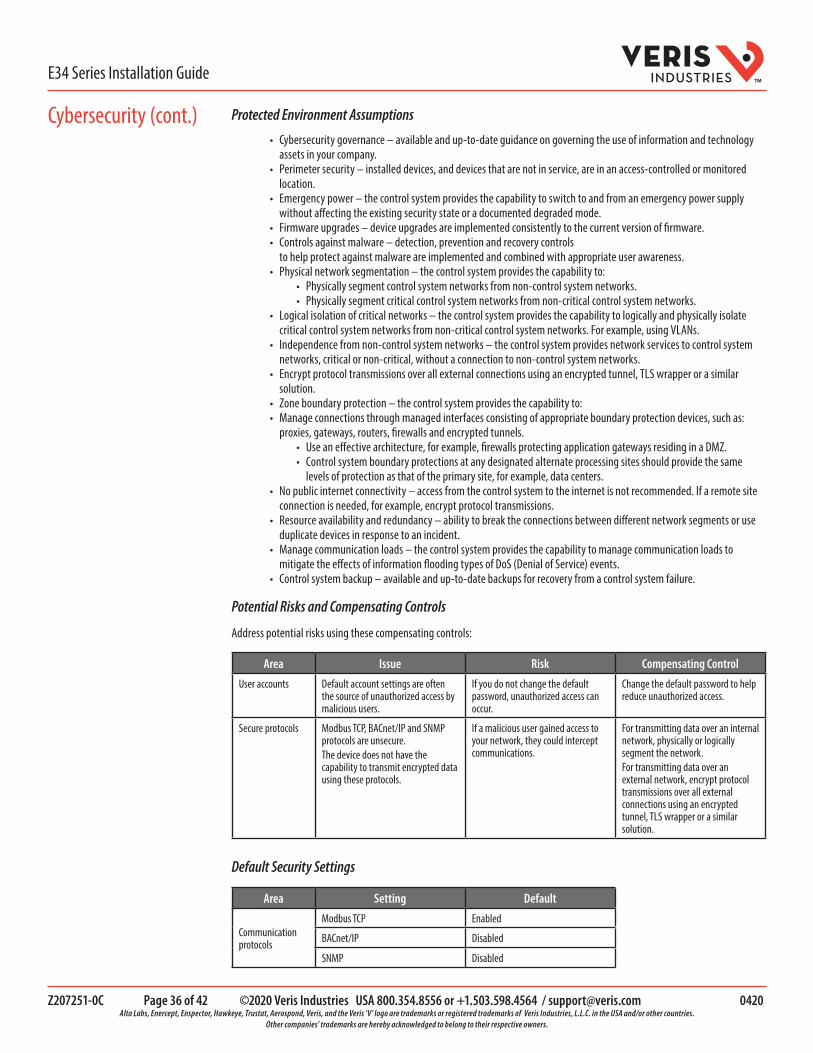
Z207251-0C Page 36 of 42 ©2020 Veris Industries USA 800.354.8556 or +1.503.598.4564 / [email protected] 0420 Alta Labs, Enercept, Enspector, Hawkeye, Trustat, Aerospond, Veris, and the Veris ‘V’ logo are trademarks or registered trademarks of Veris Industries, L.L.C. in the USA and/or other countries.
Other companies’ trademarks are hereby acknowledged to belong to their respective owners.
E34 Series Installation GuideTM
Protected Environment Assumptions
• Cybersecurity governance – available and up-to-date guidance on governing the use of information and technology assets in your company.
• Perimeter security – installed devices, and devices that are not in service, are in an access-controlled or monitored location.
• Emergency power – the control system provides the capability to switch to and from an emergency power supply without affecting the existing security state or a documented degraded mode.
• Firmware upgrades – device upgrades are implemented consistently to the current version of firmware.• Controls against malware – detection, prevention and recovery controls
to help protect against malware are implemented and combined with appropriate user awareness.• Physical network segmentation – the control system provides the capability to:
• Physically segment control system networks from non-control system networks.• Physically segment critical control system networks from non-critical control system networks.
• Logical isolation of critical networks – the control system provides the capability to logically and physically isolate critical control system networks from non-critical control system networks. For example, using VLANs.
• Independence from non-control system networks – the control system provides network services to control system networks, critical or non-critical, without a connection to non-control system networks.
• Encrypt protocol transmissions over all external connections using an encrypted tunnel, TLS wrapper or a similar solution.
• Zone boundary protection – the control system provides the capability to:• Manage connections through managed interfaces consisting of appropriate boundary protection devices, such as:
proxies, gateways, routers, firewalls and encrypted tunnels.• Use an effective architecture, for example, firewalls protecting application gateways residing in a DMZ.• Control system boundary protections at any designated alternate processing sites should provide the same
levels of protection as that of the primary site, for example, data centers.• No public internet connectivity – access from the control system to the internet is not recommended. If a remote site
connection is needed, for example, encrypt protocol transmissions.• Resource availability and redundancy – ability to break the connections between different network segments or use
duplicate devices in response to an incident.• Manage communication loads – the control system provides the capability to manage communication loads to
mitigate the effects of information flooding types of DoS (Denial of Service) events.• Control system backup – available and up-to-date backups for recovery from a control system failure.
Potential Risks and Compensating Controls
Address potential risks using these compensating controls:
Area Issue Risk Compensating Control
User accounts Default account settings are often the source of unauthorized access by malicious users.
If you do not change the default password, unauthorized access can occur.
Change the default password to help reduce unauthorized access.
Secure protocols Modbus TCP, BACnet/IP and SNMP protocols are unsecure.The device does not have the capability to transmit encrypted data using these protocols.
If a malicious user gained access to your network, they could intercept communications.
For transmitting data over an internal network, physically or logically segment the network.For transmitting data over an external network, encrypt protocol transmissions over all external connections using an encrypted tunnel, TLS wrapper or a similar solution.
Default Security Settings
Area Setting Default
Communication protocols
Modbus TCP Enabled
BACnet/IP Disabled
SNMP Disabled
Cybersecurity (cont.)

Z207251-0C Page 37 of 42 ©2020 Veris Industries USA 800.354.8556 or +1.503.598.4564 / [email protected] 0420 Alta Labs, Enercept, Enspector, Hawkeye, Trustat, Aerospond, Veris, and the Veris ‘V’ logo are trademarks or registered trademarks of Veris Industries, L.L.C. in the USA and/or other countries.
Other companies’ trademarks are hereby acknowledged to belong to their respective owners.
E34 Series Installation GuideTM
PasswordsRecommendations to optimize cybersecurity in a protected environment:
• Document and store passwords and usernames in a protected location.• Change the default password to help reduce unauthorized access. Default account settings are often the source of
unauthorized access by malicious users.• Use complex passwords or passphrases.• Follow user account management tasks as described by your organization or contact your network administrator, for
example, maximum password age or history policies.
Default Password and User Accounts
Accessing the GUI for the First Time with Firmware Version 1.027 or Higher
Open the web browser and enter the IP address of the device into the address/URL field on the browser. Press enter. A “Web Server Security Unconfigured” warning message screen appears. Read the instructions carefully before you click the “Use HTTPS (Recommended)” button.
The “Log In” screen appears. Enter the “Username” and “Password”.
Default account settings:
Username Password
admin
The default password is an alphanumeric string that is unique for each device and can be found on a label affixed to the top of the meter and also on a duplicate label included in the box with the meter. Example of a default password barcode label: dX2oO8$A%e94SVoXNote: It is recommended for users to change the default factory-set password to a complex password after logging in to the GUI.
Cybersecurity (cont.)
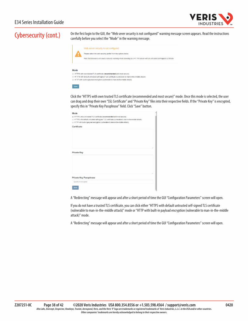
Z207251-0C Page 38 of 42 ©2020 Veris Industries USA 800.354.8556 or +1.503.598.4564 / [email protected] 0420 Alta Labs, Enercept, Enspector, Hawkeye, Trustat, Aerospond, Veris, and the Veris ‘V’ logo are trademarks or registered trademarks of Veris Industries, L.L.C. in the USA and/or other countries.
Other companies’ trademarks are hereby acknowledged to belong to their respective owners.
E34 Series Installation GuideTM
On the first login to the GUI, the “Web sever security is not configured” warning message screen appears. Read the instructions carefully before you select the “Mode” in the warning message.
Click the “HTTPS with own trusted TLS certificate (recommended and most secure)” mode. Once this mode is selected, the user can drag and drop their own “SSL Certificate” and “Private Key” files into their respective fields. If the “Private Key” is encrypted, specify this in “Private Key Passphrase” field. Click “Save” button.
A “Redirecting” message will appear and after a short period of time the GUI “Configuration Parameters” screen will open.
If you do not have a trusted TLS certificate, you can click either “HTTPS with default untrusted self-signed TLS certificate (vulnerable to man-in-the-middle attack)” mode or “HTTP with built-in payload encryption (vulnerable to man-in-the-middle attack)” mode.
A “Redirecting” message will appear and after a short period of time the GUI “Configuration Parameters” screen will open.
Cybersecurity (cont.)Cybersecurity (cont.)

Z207251-0C Page 39 of 42 ©2020 Veris Industries USA 800.354.8556 or +1.503.598.4564 / [email protected] 0420 Alta Labs, Enercept, Enspector, Hawkeye, Trustat, Aerospond, Veris, and the Veris ‘V’ logo are trademarks or registered trademarks of Veris Industries, L.L.C. in the USA and/or other countries.
Other companies’ trademarks are hereby acknowledged to belong to their respective owners.
E34 Series Installation GuideTM
Changing Passwords
LOSS OF ACCESS• Record your device’s user and password information in a secure
location.
Failure to follow these instructions can result in data lossand loss of access to the device.
NOTICE
LOSS OF DATA OR PRODUCT CONFIGURATION• Do not let unauthorized personnel gain physical access to the
device.
Failure to follow these instructions can result in data lossand loss of access to the device.
NOTICE
After logging to the GUI for the first time, it is recommended to change the default factory-set password.
In the “Configuration Parameters” window, click the button labelled “Diagnostics & Debugging”. The “Navigation” window appears.
On the “Navigation” window, under the product gateway, click “Setup”. Navigate to “User Management”. Click the “Password” tab.
Enter the new alphanumeric complex password in the “Password” and “Confirm Password” fields. Click “Confirm” to save the changes.
To confirm the changes, click the “Logout” button and access the GUI with the new password.
Hardening the Device
Recommendations to optimize cybersecurity in a protected environment:
• Harden the device according to your company policies and standards.• Review assumptions about protected environments and address potential risks and mitigation strategies. See
“Product defense-in-depth” for more details.• Change the default passwords/passcodes. See “Changing passwords” for more details.• Change the communication protocol ports from their default values. This lowers the predictability of port use.• Disable communication protocol ports when they are not in use. This reduces the attack surface.
Firmware Upgrades
When device firmware is upgraded – security configuration remains the same until changed, including usernames and passwords/passcodes. It is recommended to review security configuration after an upgrade to analyze privileges for new or changed device features and revoke or apply them according to your company policies and standards.
Secure Disposal Guidelines
Use the Secure disposal checklist when disposing a device to help prevent potential disclosure of data.
Cybersecurity (cont.)

Z207251-0C Page 40 of 42 ©2020 Veris Industries USA 800.354.8556 or +1.503.598.4564 / [email protected] 0420 Alta Labs, Enercept, Enspector, Hawkeye, Trustat, Aerospond, Veris, and the Veris ‘V’ logo are trademarks or registered trademarks of Veris Industries, L.L.C. in the USA and/or other countries.
Other companies’ trademarks are hereby acknowledged to belong to their respective owners.
E34 Series Installation GuideTM
Secure Disposal Checklist
Record activities: Document disposal actions according to your company policies and standards to keep a record of activities.
Decommission related rules and sanitize records:
• Follow decommission and sanitization tasks as described by your organization or contact your network administrator.• Decommission network and security rules, e.g. a firewall rule that could be used to get past the firewall.• Perform records tracking sanitization tasks to remove records in related systems, e.g. monitoring SNMP servers.
Disposal and reuse: See Disposal, resuse, recycling for more details.
Disposal and Reuse
Before removing the device from its intended environment, follow the Secure disposal guidelines in this document.
Follow device removal tasks described by your organization or contact your network administrator to determine a responsible method of disposal.
Dispose the device according to the legislation of the country. Some regulatory organizations include:
• The United States Environmental Protection Agency (EPA) for guidance on the sustainable management of electronics.• The EPA provides an Electronic Product Environmental Assessment Tool (EPEAT) that helps assess the
environmental attributes of electronics.• The European Waste Electrical & Electronic Equipment Directive
(WEEE Directive) is the community directive on waste electrical and electronic equipment.• The European Restriction of Hazardous Substances Directive (RoHS) directive on the restriction of the use of certain
hazardous substances in electrical and electronic equipment.
UNAUTORIZED OR UNINTENDED ACCESS TOCONFIDENTIAL DATA •
•
Store devices that are not in service in an access-controlled ormonitored location.Physically destroy devices that are decommissioned.
Failure to follow these instructions can result in unauthorized or unintended access to sensitive or securecustomer data.
NOTICE
Device Disposal
It is recommended that the entire device is physically destroyed. Destroying the device helps prevent potential disclosure of data contained in the device that was not removed.
Device Reuse
Store the device in a location that is access controlled or monitored if there is potential for reuse.
Cybersecurity (cont.)

Z207251-0C Page 41 of 42 ©2020 Veris Industries USA 800.354.8556 or +1.503.598.4564 / [email protected] 0420 Alta Labs, Enercept, Enspector, Hawkeye, Trustat, Aerospond, Veris, and the Veris ‘V’ logo are trademarks or registered trademarks of Veris Industries, L.L.C. in the USA and/or other countries.
Other companies’ trademarks are hereby acknowledged to belong to their respective owners.
E34 Series Installation GuideTM
Part ID Description
AE001 E3x MCB Cover
CBL008 Flat ribbon cable, 50 x 28 AWG, 1.5 ft. (0.45 m)
CBL016 Flat ribbon cable, 50 x 28 AWG, 4 ft. (1.2 m)
CBL017 Flat ribbon cable, 50 x 28 AWG, 5 ft. (1.5 m)
CBL018 Flat ribbon cable, 50 x 28 AWG, 6 ft. (1.8 m)
CBL019 Flat ribbon cable, 50 x 28 AWG, 8 ft. (2.4 m)
CBL020 Flat ribbon cable, 50 x 28 AWG, 10 ft. (3.0 m)
CBL021 Flat ribbon cable, 50 x 28 AWG, 20 ft. (6.1 m)
CBL022 Round ribbon cable, 50 x 28 AWG, 4 ft. (1.2 m)
CBL023 Round ribbon cable, 50 x 28 AWG, 10 ft. (3 m)
CBL024 Round ribbon cable, 50 x 28 AWG, 20 ft. (6 m)
CBL025 Flat ribbon cable, 50 x 28 AWG, 2 m
CBL026 Flat ribbon cable, 50 x 28 AWG, 4 m
CBL027 Flat ribbon cable, 50 x 28 AWG, 6 m
CBL031 Round ribbon cable, 50 x 28 AWG, 1.5 ft. (0.45 m)
CBL032 Round ribbon cable, 50 x 28 AWG, 2.5 ft. (0.76 m)
Recommended Accessories
Problem Solution
Product is not communicating over Modbus daisy chain
• Check the unit Modbus address to ensure that each device on the daisy chain has a unique address.• Check Parity.• Check the communications wiring.• Check that the daisy chain is properly terminated.
RX LED is solid (E34A models) • Check for reversed polarity on Modbus comms.• Check for sufficient biasing on the Modbus bus. Modbus physical specification calls for 450-650 Ω biasing. This is usually provided by the master.
The main board has a slow flashing amber light (E34A models)
• One or more channels is clipping. This can be caused by a signal greater than the split-core size or 277 V L-N, or by a signal with high THD near the gain stage switching points (1.5 A and 10 A).
The main board has a flashing green light (E34A models)
• Everything is wired properly and the main board has power.
The main board has a flashing or solid red light (E34A models)
• Light may be red briefly while device powers up.• If light is red for more the 60 sec. device has encountered a diagnostic event. Contact technical support.• The light will flash red if incompatible CT strips or adapter boards are detected
Power factor reading is not as expected • Verify voltage taps are connected in appropriate phase rotation.• Verify phase rotation of breakers (firmware rev. 1.012 or higher allows for custom rotation if needed).
Current is reading zero, even when small currents are still flowing through circuit
• The product cuts off measurements if the current on any input is less than 0.1% of the full range current setting used for any CT, and will set the reporting register to 0 mA for currents near or below this range.
Non-zero current or power readings are showing on one or more unused channels.
The CT range setting of any channel that does not have a CT actually connected should be set to zero. Channels without CTs connected will pick up noise that can cause non-zero readings if the range is not zero. When CTs are properly connected, the impedance of the CT itself will absorb spurious noise at the proper range setting.
Troubleshooting

Z207251-0C Page 42 of 42 ©2020 Veris Industries USA 800.354.8556 or +1.503.598.4564 / [email protected] 0420 Alta Labs, Enercept, Enspector, Hawkeye, Trustat, Aerospond, Veris, and the Veris ‘V’ logo are trademarks or registered trademarks of Veris Industries, L.L.C. in the USA and/or other countries.
Other companies’ trademarks are hereby acknowledged to belong to their respective owners.
E34 Series Installation GuideTM
China RoHS Compliance Information - Environment Friendly Use Period (EFUP) Table
本表格依据SJ/T11364的规定编制。
O: 表示该有害物质在该部件所有均质材料中的含量均在GB/T 26572规定的限量要求以下。
X: 表示该有害物质至少在该部件的某一均质材料中的含量超出GB/T 26572规定的限量要求。
(企业可在此处,根据实际情况对上表中打 的技术原因进行进一步说明。)
This table is made according to SJ/T 11364.O: indicates that the concentration of hazardous substance in all of the homogeneous materials for this part is below the limit as stipulated in GB/T 26572.X: indicates that concentration of hazardous substance in at least one of the homogeneous materials used for this part
X O O O O O
is above the limit as stipulated in GB/T 26572
Z000057-0B
部件名称
Part Name有害物质 - Hazardous Substances
铅 (Pb) 汞 (Hg) 镉 (Cd) 六价铬 (Cr (VI)) 多溴联苯 (PBB) 多溴二苯醚 (PBDE)电子件
Electronic