Embed Size (px)
Citation preview

CameraSun Shade
Dummy cover or IR LED unit (optional)
Front glass
Wiper
PAN rotation part
Mounting pedestal
Tilt arm
Tilt lock
Side cover
Waterproof EXT I/O connector
Waterproof RJ45 connector
Waterproof power supply connector
Bottom wiring port Side wiring port*1
Mounting pedestal fixing screws ×4 (locally procured)
Dummy cover or IR LED unit (optional)
IMPORTANT:• When the camera is initialized, the settings including the network settings will be initialized. Note that the
CRT key (SSL encryption key) used for the HTTPS protocol and the preset entry will not be initialized.• Before initializing the settings, it is recommended to write down the settings in advance.• Do not turn off the power of the camera during the process of initialization. Otherwise, it may
fail to initialize and may cause malfunction.
STATUS indicator behaviors• When the power is turned on Lights orange → Lights off → Blinks orange → Lights orange (When the network connection is not established) Lights orange → Lights off → Blinks orange → Blinks green → Lights green
(When the network connection is established)• During the standby or connection Lights orange (When the cable is not connected) Lights green (When the cable is connected)• During the upgrade process Blinks orange• During the initialization Lights orange → Lights off → Blinks orange →
Lights orange• Port forwarding error caused by the UPnP function Blinks orange (in 2 seconds intervals
(on for 1 second / off for 1 second))• Trouble happening on the camera Blinks red• When the installation position is abnormal Lights red
• This manual describes the installation procedures, network camera installation, cable connec-tions, and adjustment.
• Before reading this manual, be sure to read the Important Information (included in the CD-ROM).
Parts and functions
Standard accessories Cable preparationImportant safety instructions ......................... 1 pc.Installation Guide (this document) ................. 1 set
Warranty card*1 ............................................ 1 setCD-ROM*2 .................................................... 1 pc.Code label*3.................................................. 1 pc.
Attach the provided waterproof connector to the cable to be connected to the camera.* When a conduit is used for wiring, always check its size before installing the waterproof connector.
Otherwise, the cable may not be able to pass through the conduit depending on the number of cables used and the waterproof connector in use.
* Always make preparations before the procedure “[3] Attach the waterproof RJ45 connector (acces-sory) to the Ethernet cable.”
* Prepare [1] and [2] when necessary.
*1 This product comes with several types of warranties. Each warranty is only applicable to the prod-ucts purchased in the regions indicated on the relevant warranty.
*2 The CD-ROM contains the operating instructions and different kinds of tool software programs.*3 This label may be required for network management. The network administrator shall retain the code label.
Waterproof power supply connector (plug side) ...............................................................................1 setWaterproof EXT I/O connector (plug side) ........................................................................................1 setWaterproof RJ45 connector (plug side) ............................................................................................1 setWasher nozzle mounting bracket A ..................................................................................................1 pc.Washer nozzle mounting bracket B..................................................................................................1 pc.Fixing screws for the washer nozzle mounting bracket B ..............................3 pcs. (of them, 1 for spare)Attachment plate .............................................................................................................................1 pc.Fixing screws for attachment plate ................................................................. 5 pc. (of them, 1 for spare)Fixing nuts for attachment plate ..................................................................... 5 pc. (of them, 1 for spare)Spring washer ............................................................................................... 5 pc. (of them, 1 for spare)Flat washer .................................................................................................. 10 pc. (of them, 2 for spare)Safety wire .......................................................................................................................................1 pc.Wire clamper ...................................................................................................................................1 pc.Bit (Hex wrench, screw size 6.35 mm {1/4 inches} T20)...................................................................1 pc.
Hub/Router
AC100-240 V 50/60 Hz
Ethernet cable (category 5e or better, straight)
Ethernet cable (category 5e or better, straight)
PC*2
Tested PoE injector*1
Installation procedure
• Attach the provided waterproof connector to the cable to be wired to the inside of the ceiling or floor or along various surfaces, and run the cable through the conduit. (Please choose a conduit of a suitable size to allow the connector to pass through.)
Cable preparation
• Remove the side cover of the camera so that the wire connection part is visible. (Step.4)• If necessary, install the extension unit (IR LED unit) (optional) if necessary. (Step.5)• If you want to shoot the foot area, bend the tilt arm of the camera forward. (Step.6)• Fix the camera onto the installation location. (Step.8)
* Install the washer nozzle mounting bracket pre-fitted with a (recommended) washer nozzle at the same time.
Installation
• Connect each waterproof connector to the camera, and fix the side cover back to its original position.
Connecting wires
(→ Refer to the leaflet “Configuring the camera so that it can be accessed from a PC”)• Turn on the power supply, and configure the camera so
that it can be accessed via network.
Configuring the camera so that it can be accessed from a PC
• About the INITIAL SW (Initial switch)Follow the steps below to initialize the network camera.➀ Cut the power supply to the camera either by unplugging the AC power cord or by turning off the
power supply of the tested PoE injector.➁ Turn on the power of the camera while holding down the INITIAL SW, and keep the INITIAL SW held
down for 10-15 seconds. In about 2 minutes after releasing the INITIAL SW, the camera will start up and the settings, including the network settings, will be initialized.
System connection diagramThe camera can be powered by the AC power supply or the tested PoE injector as shown in the follow-ing illustration.
*1 For the related information on applicable tested PoE injectors, refer to our website (http://security.panasonic.com/support/info/).
*2 Use an Ethernet cable (category 5e or better, cross) when directly connecting the camera to a PC.
*1 The female thread for conduit is compliant with ANSI NPSM (parallel pipe threads) 3/4 or ISO 228-1 (parallel pipe threads) G3/4.
[1] Attach the waterproof EXT I/O connector (accessory) to the cable* The parts to be used in ➁ and ➂ are in the bag of the waterproof EXT I/O connector (plug side) set.<Locally procured items> • Multi-core cable ø6.2 ~ 7 mm {ø1/4 ~ 9/32 inches} Size of the internal lead wire AWG26 – AWG30, coated external diameter of ø1 mm {ø1/32 inches} or below • Manual crimping tool HT-102/HR30-1, made by Hirose Electric Co., Ltd. • Extraction tool (if necessary) HR30-TP, made by Hirose Electric Co., Ltd.
➀ Thread each part of the waterproof EXT I/O connector (accessory) through the cable in sequence
Pass the cord tube, cord clamp, gasket, spring and coupling in sequence through the plug beforehand. Prepare wire ends according to the dimensions shown in the illustration below.
Case block Coupling Spring Cord clamp
Gasket Cord tube
Cable15 ~ 20 mm {19/32 ~ 25/32 inches}2.0 mm (+0, -0.5)
{3/32 (+0, -1/32) inches}
➁ Crimp the contact (accessory) to the cable
➂ Insert the contact into the terminal hole on the case block
• After inserting the contact, pull the lead wire lightly, and ensure that it is firmly fixed to the terminal hole of the waterproof EXT I/O connector.
<Pin layout of the waterproof EXT I/O connector>Pin. 1 LINE IN Pin. 7 Alarm IN1Pin. 2 Audio/LINE_GND Pin. 8 N.C.Pin. 3 Audio OUT Pin. 9 Relay-Pin. 4 Alarm GND Pin. 10 Relay-Pin. 5 Alarm IN3/AUX Pin. 11 Relay+Pin. 6 Alarm IN2/Alarm OUT Pin. 12 Relay+
➃ Mount the coupling and the spring on the case block, and tighten the cord tube with the gasket and the cord clamp
• Align the mark “ ” on the coupling with the side of pin ➀ of the case block, and install the coupling and the spring in sequence.
• Shift the cord tube, and insert the cord clamp and the gasket in the cord tube.
• Align the cord tube with the coupling part, and rotate to tighten them as shown in the right illustration. (Recommended tightening torque: 0.5 N·m {0.37 lbf·ft})
➄ Connect the washer unit (locally procured)
Pin. 9 Relay-Pin. 10 Relay-Pin. 11 Relay+Pin. 12 Relay+
Waterproof EXT I/O connector side
Circuit diagram
Washer unit connection terminal side
Washer-Washer+
NozzleWasher hose
* Please use the washer unit that has been insulated from the commercial AC power.
➅ EXT I/O terminal ratings • Alarm IN1, Alarm IN2, Alarm IN3 Input specification: No-voltage make contact input (4 V ~ 5 V DC, internally pulled up) OFF: Open or 4 V ~ 5 V DC ON: Make contact with GND (required drive current: 1 mA or more) • Alarm OUT, AUX OUT Output specification: Open collector output (maximum applied voltage: 20 V DC) OPEN: 4 V ~ 5 V DC by internal pull-up CLOSE: Output voltage 1 V DC or less (maximum drive current: 50 mA) • Max. ratings of Relay+ and Relay-: DC 25 V, 4.0 A * The default of EXT I/O terminals is “Off”.
[2] Attach the waterproof power supply connector (accessory) to the cable* The parts to be used in ➀ and ➁ are in the bag of the waterproof power supply connector (plug side) set.<Locally procured items> • Power cable Cable diameter ø6 ~ 10 mm {ø1/4 ~ 13/32 inches} Cross-sectional area of the wire conductor 0.75 or 1.25 mm2 {0.0012 or 0.0019 inche2} Number of wires 3 (for L, N and FG) Insulation material Polyethylene (recommended)
➀ Preparations • Assemble the internal strain relief as shown in the right illustration,
and install the fixing bracket. (Tighten the screws temporarily as the power cord will go in between
the bracket and the formed part.) • Install the mounting gasket on the clamp
ring as shown in the right illustration. (Please use the applicable parts as described below for the mounting gasket according to the external diameter of the power cord.)
Small internal diameter... Power cord size 6.0 ~ 9.0 mm {1/4 ~ 11/32 inches}
Large internal diameter... Power cord size 9.0 ~ 10.0 mm {11/32 ~ 13/32 inches}
➁ Thread each part of the waterproof power supply connector through the power cable in the sequence as shown in the illustration below
• Cable nut → Clamp ring (with mounting gasket) → Back shell → Internal strain relief
Internal strain relief
Back shell
Clamp ring (with mounting gasket)
Cable nut
Cable
➂ Prepare the cable end in the following dimensions, and twist the core. Process tolerance: +1 mm/-0 mm {+1/32 / -0 inches}
Dimensions A (cable sheath) Dimensions B (bare core wire)Live, Neutral 18 mm {23/32 inches} 7 mm {9/32 inches}GND 20 mm {25/32 inches} 9 mm {11/32 inches}
➃ While the core of the lead wire is inserted into the connecting hole at the back of the connector body, tighten the screw on the connector body, and connect and fix the lead wire to each terminal. For safety purpose, please read the following connection instructions carefully.* There is a cutout on the connector coupling nut.
Align the position of the screw to be tightened with the cutout on the coupling nut, and tighten the screw with a flathead screwdriver. (Refer to the upper right illustration.) (Recommended tightening torque: 0.5 N·m {0.37 lbf·ft}
During fore positionDuring upright position
Clamp ring
Mounting gasket
Small internal diameter
Large internal diameter
Case block
Waterproof EXT I/O connector (accessory)Terminal layout of the contact insertion side
Connector Pin 1 Live Pin 2 Neutral Pin 3 N.C. GND
Cutout
Coupling nut
Pin 2
Pin 1 Pin 3
GND
➄ Insert and fix the internal strain relief on the connector as shown in the illustration. Next, rotate the screw of the internal strain relief, and fix the power cord firmly with the fixing bracket.(Recommended tightening torque: 0.5 N·m {0.37 lbf·ft})
➅ Align the coupling nut to the fixing position to prevent the connector from rotating, and rotate to fix the back shell. Install the clamp ring (with mounting gasket) on the back shell, and tighten it with a cable nut. (Recommended tightening torque: 1.5 ~ 2.0 N·m {1.11 ~ 1.48 lbf·ft}
Coupling nut Back shell Cable nutClamp ring(with mounting gasket)
Screws × 2
Internal strain relief
Internal strain relief (accessory)
Fixing bracket (accessory)
Screws x 2 (accessory)
Pin ➀ Coupling
Spring
Cord tube (Including the cord clamp and the gasket)
Case blockInstallation GuideIncluded Installation Instructions
Network Camera
Model No. WV-SUD638
WV-SUD638-H / WV-SUD638-T(Natural silver)
(Gray) (Brown)
fles0816-1057 PGQX2063YA Printed in China
For U.S. and Canada:
Panasonic System Communications Company of North America,Unit of Panasonic Corporationof North Americawww.panasonic.com/business/For customer support, call 1.800.528.6747Two Riverfront Plaza, Newark, NJ 07102-5490
Panasonic Canada Inc.5770 Ambler Drive, Mississauga,Ontario, L4W 2T3 Canada (905)624-5010www.panasonic.ca
For Europe and other countries:
Panasonic Corporationhttp://www.panasonic.com
Panasonic Corporation Osaka, Japan
Authorised Representative in EU:
Panasonic Testing CentrePanasonic Marketing Europe GmbHWinsbergring 15, 22525 Hamburg, Germany
© Panasonic Corporation 2017
Switch plate
STATUS indicator
ACT Indicator
LINK indicator
INITIAL SW (Initial switch)
ab
Connector body
2
43
5
7
6
8
56789
�����
��
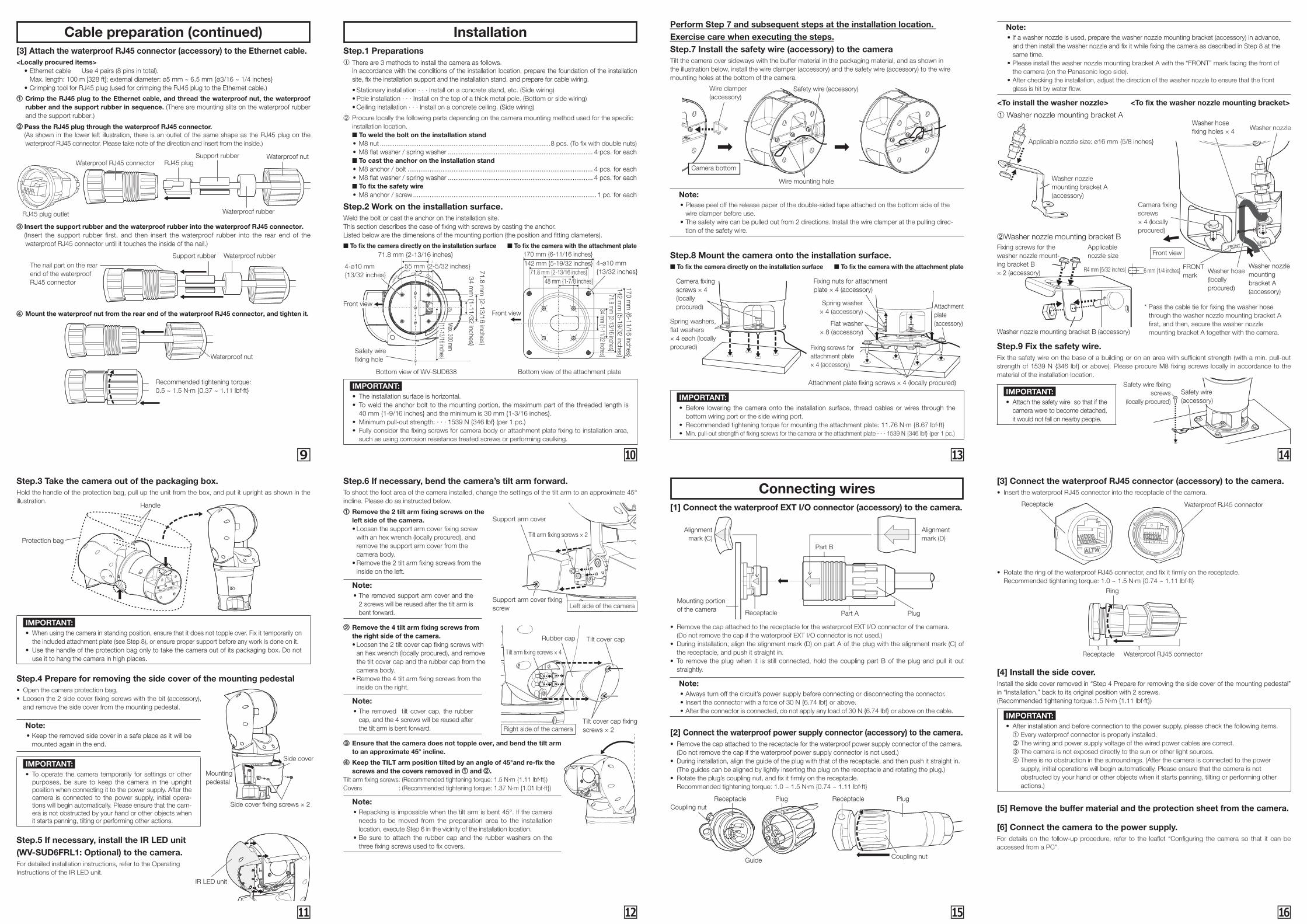
Cable preparation (continued) Installation
Connecting wires
Step.1 Preparations➀ There are 3 methods to install the camera as follows.
In accordance with the conditions of the installation location, prepare the foundation of the installation site, fix the installation support and the installation stand, and prepare for cable wiring.
• Stationary installation ∙ ∙ ∙ Install on a concrete stand, etc. (Side wiring) • Pole installation ∙ ∙ ∙ Install on the top of a thick metal pole. (Bottom or side wiring) • Ceiling installation ∙ ∙ ∙ Install on a concrete ceiling. (Side wiring)
➁ Procure locally the following parts depending on the camera mounting method used for the specific installation location.■ To weld the bolt on the installation stand
• M8 nut .............................................................................................8 pcs. (To fix with double nuts) • M8 flat washer / spring washer ............................................................................... 4 pcs. for each
■ To cast the anchor on the installation stand • M8 anchor / bolt ..................................................................................................... 4 pcs. for each • M8 flat washer / spring washer ............................................................................... 4 pcs. for each
■ To fix the safety wire • M8 anchor / screw ....................................................................................................1 pc. for each
Step.2 Work on the installation surface.Weld the bolt or cast the anchor on the installation site.This section describes the case of fixing with screws by casting the anchor.Listed below are the dimensions of the mounting portion (the position and fitting diameters).
■ To fix the camera directly on the installation surface ■ To fix the camera with the attachment plate
Front view
4-ø10 mm {13/32 inches}
170 mm {6-11/16 inches}
170 mm
{6-11/16 inches}
142 mm {5-19/32 inches}
142 mm
{5-19/32 inches}
71.8 mm {2-13/16 inches}
71.8 mm
{2-13/16 inches}
48 mm {1-7/8 inches}
34 mm {1-11/32 inches}
Front view
Safety wire fixing hole
4-ø10 mm {13/32 inches}
71.8 mm {2-13/16 inches}
71.8 mm
{2-13/16 inches}
55 mm {2-5/32 inches}
34 mm
{1-11/32 inches}
Max. 300 m
m
{11-13/16 inches}
Bottom view of WV-SUD638 Bottom view of the attachment plate
Step.3 Take the camera out of the packaging box.Hold the handle of the protection bag, pull up the unit from the box, and put it upright as shown in the illustration.
Step.4 Prepare for removing the side cover of the mounting pedestal• Open the camera protection bag.• Loosen the 2 side cover fixing screws with the bit (accessory),
and remove the side cover from the mounting pedestal.
Step.5 If necessary, install the IR LED unit (WV-SUD6FRL1: Optional) to the camera.For detailed installation instructions, refer to the Operating Instructions of the IR LED unit.
Step.8 Mount the camera onto the installation surface.■ To fix the camera directly on the installation surface ■ To fix the camera with the attachment plate
Camera fixing screws × 4 (locally procured)
Spring washers, flat washers × 4 each (locally procured)
Spring washer × 4 (accessory)
Attachment plate fixing screws × 4 (locally procured)
Attachment plate (accessory)Flat washer
× 8 (accessory)
Fixing nuts for attachment plate × 4 (accessory)
Fixing screws for attachment plate × 4 (accessory)
IMPORTANT:• Before lowering the camera onto the installation surface, thread cables or wires through the
bottom wiring port or the side wiring port.• Recommended tightening torque for mounting the attachment plate: 11.76 N∙m {8.67 lbf·ft}• Min. pull-out strength of fixing screws for the camera or the attachment plate ∙ ∙ ∙ 1539 N {346 lbf} (per 1 pc.)
Step.9 Fix the safety wire.Fix the safety wire on the base of a building or on an area with sufficient strength (with a min. pull-out strength of 1539 N {346 lbf} or above). Please procure M8 fixing screws locally in accordance to the material of the installation location.
Perform Step 7 and subsequent steps at the installation location. Exercise care when executing the steps.Step.7 Install the safety wire (accessory) to the cameraTilt the camera over sideways with the buffer material in the packaging material, and as shown in the illustration below, install the wire clamper (accessory) and the safety wire (accessory) to the wire mounting holes at the bottom of the camera.
Wire clamper (accessory)
Safety wire (accessory)
Wire mounting hole
Camera bottom
Note: • Please peel off the release paper of the double-sided tape attached on the bottom side of the
wire clamper before use. • The safety wire can be pulled out from 2 directions. Install the wire clamper at the pulling direc-
tion of the safety wire.
IMPORTANT:• The installation surface is horizontal.• To weld the anchor bolt to the mounting portion, the maximum part of the threaded length is
40 mm {1-9/16 inches} and the minimum is 30 mm {1-3/16 inches}.• Minimum pull-out strength: ∙ ∙ ∙ 1539 N {346 lbf} (per 1 pc.)• Fully consider the fixing screws for camera body or attachment plate fixing to installation area,
such as using corrosion resistance treated screws or performing caulking.
IMPORTANT:• To operate the camera temporarily for settings or other
purposes, be sure to keep the camera in the upright position when connecting it to the power supply. After the camera is connected to the power supply, initial opera-tions will begin automatically. Please ensure that the cam-era is not obstructed by your hand or other objects when it starts panning, tilting or performing other actions.
IMPORTANT:• When using the camera in standing position, ensure that it does not topple over. Fix it temporarily on
the included attachment plate (see Step 8), or ensure proper support before any work is done on it.• Use the handle of the protection bag only to take the camera out of its packaging box. Do not
use it to hang the camera in high places.
[1] Connect the waterproof EXT I/O connector (accessory) to the camera.
Alignment mark (C)
Alignment mark (D)
Part B
Part A PlugReceptacle
Mounting portion of the camera
• Remove the cap attached to the receptacle for the waterproof EXT I/O connector of the camera.(Do not remove the cap if the waterproof EXT I/O connector is not used.)
• During installation, align the alignment mark (D) on part A of the plug with the alignment mark (C) of the receptacle, and push it straight in.
• To remove the plug when it is still connected, hold the coupling part B of the plug and pull it out straightly.
Note: • Always turn off the circuit’s power supply before connecting or disconnecting the connector. • Insert the connector with a force of 30 N {6.74 lbf} or above. • After the connector is connected, do not apply any load of 30 N {6.74 lbf} or above on the cable.
[2] Connect the waterproof power supply connector (accessory) to the camera.• Remove the cap attached to the receptacle for the waterproof power supply connector of the camera.
(Do not remove the cap if the waterproof power supply connector is not used.)• During installation, align the guide of the plug with that of the receptacle, and then push it straight in.
(The guides can be aligned by lightly inserting the plug on the receptacle and rotating the plug.)• Rotate the plug’s coupling nut, and fix it firmly on the receptacle.
Recommended tightening torque: 1.0 ~ 1.5 N∙m {0.74 ~ 1.11 lbf∙ft}
Guide
ReceptacleReceptacleCoupling nut
Plug Plug
Coupling nut
[3] Connect the waterproof RJ45 connector (accessory) to the camera.• Insert the waterproof RJ45 connector into the receptacle of the camera.
Receptacle Waterproof RJ45 connector
• Rotate the ring of the waterproof RJ45 connector, and fix it firmly on the receptacle. Recommended tightening torque: 1.0 ~ 1.5 N∙m {0.74 ~ 1.11 lbf∙ft}
Ring
Receptacle Waterproof RJ45 connector
[4] Install the side cover.Install the side cover removed in “Step 4 Prepare for removing the side cover of the mounting pedestal” in “Installation.” back to its original position with 2 screws.(Recommended tightening torque:1.5 N∙m {1.11 lbf·ft})
IMPORTANT:• After installation and before connection to the power supply, please check the following items.
➀ Every waterproof connector is properly installed. ➁ The wiring and power supply voltage of the wired power cables are correct.➂ The camera is not exposed directly to the sun or other light sources. ➃ There is no obstruction in the surroundings. (After the camera is connected to the power
supply, initial operations will begin automatically. Please ensure that the camera is not obstructed by your hand or other objects when it starts panning, tilting or performing other actions.)
[5] Remove the buffer material and the protection sheet from the camera.
[6] Connect the camera to the power supply.For details on the follow-up procedure, refer to the leaflet “Configuring the camera so that it can be accessed from a PC”.
Side cover
Side cover fixing screws × 2
Mounting pedestal
Note: • Keep the removed side cover in a safe place as it will be
mounted again in the end.
IR LED unit
[3] Attach the waterproof RJ45 connector (accessory) to the Ethernet cable.<Locally procured items> • Ethernet cable Use 4 pairs (8 pins in total).
Max. length: 100 m [328 ft]; external diameter: ø5 mm ~ 6.5 mm {ø3/16 ~ 1/4 inches} • Crimping tool for RJ45 plug (used for crimping the RJ45 plug to the Ethernet cable.)
➀ Crimp the RJ45 plug to the Ethernet cable, and thread the waterproof nut, the waterproof rubber and the support rubber in sequence. (There are mounting slits on the waterproof rubber and the support rubber.)
➁ Pass the RJ45 plug through the waterproof RJ45 connector. (As shown in the lower left illustration, there is an outlet of the same shape as the RJ45 plug on the
waterproof RJ45 connector. Please take note of the direction and insert from the inside.)
Waterproof RJ45 connector
RJ45 plug outlet
RJ45 plugSupport rubber
Waterproof rubber
Waterproof nut
➂ Insert the support rubber and the waterproof rubber into the waterproof RJ45 connector. (Insert the support rubber first, and then insert the waterproof rubber into the rear end of the
waterproof RJ45 connector until it touches the inside of the nail.)
The nail part on the rear end of the waterproof RJ45 connector
Support rubber Waterproof rubber
➃ Mount the waterproof nut from the rear end of the waterproof RJ45 connector, and tighten it.
Recommended tightening torque:0.5 ~ 1.5 N∙m {0.37 ~ 1.11 lbf·ft}
Waterproof nut
Note: • If a washer nozzle is used, prepare the washer nozzle mounting bracket (accessory) in advance,
and then install the washer nozzle and fix it while fixing the camera as described in Step 8 at the same time.
• Please install the washer nozzle mounting bracket A with the “FRONT” mark facing the front of the camera (on the Panasonic logo side).
• After checking the installation, adjust the direction of the washer nozzle to ensure that the front glass is hit by water flow.
<To install the washer nozzle> <To fix the washer nozzle mounting bracket>
➀ Washer nozzle mounting bracket A
Applicable nozzle size: ø16 mm {5/8 inches}
Washer hose fixing holes × 4
Camera fixing screws × 4 (locally procured)
FRONT mark
Washer nozzle mounting bracket A (accessory)
Washer hose (locally procured)
R4 mm {5/32 inches}
Handle
Protection bag
Fixing screws for the washer nozzle mount-ing bracket B × 2 (accessory)
Washer nozzle
Washer nozzle mounting bracket A (accessory)
FRONT REAR➁Washer nozzle mounting bracket B
6 mm {1/4 inches}
Applicable nozzle size Front view
IMPORTANT:• Attach the safety wire so that if the
camera were to become detached, it would not fall on nearby people.
Washer nozzle mounting bracket B (accessory)
Safety wire fixing screws
(locally procured)Safety wire (accessory)
�9 � �
�� � �
Step.6 If necessary, bend the camera’s tilt arm forward.To shoot the foot area of the camera installed, change the settings of the tilt arm to an approximate 45° incline. Please do as instructed below.
➀ Remove the 2 tilt arm fixing screws on the left side of the camera.
• Loosen the support arm cover fixing screw with an hex wrench (locally procured), and remove the support arm cover from the camera body.
• Remove the 2 tilt arm fixing screws from the inside on the left.
Note: • The removed support arm cover and the
2 screws will be reused after the tilt arm is bent forward.
➁ Remove the 4 tilt arm fixing screws from the right side of the camera.
• Loosen the 2 tilt cover cap fixing screws with an hex wrench (locally procured), and remove the tilt cover cap and the rubber cap from the camera body.
• Remove the 4 tilt arm fixing screws from the inside on the right.
Note: • The removed tilt cover cap, the rubber
cap, and the 4 screws will be reused after the tilt arm is bent forward.
➂ Ensure that the camera does not topple over, and bend the tilt arm to an approximate 45° incline.
➃ Keep the TILT arm position tilted by an angle of 45°and re-fix the screws and the covers removed in ➀ and ➁.
Tilt arm fixing screws: (Recommended tightening torque: 1.5 N∙m {1.11 lbf·ft})Covers : (Recommended tightening torque: 1.37 N∙m {1.01 lbf·ft})
Note: • Repacking is impossible when the tilt arm is bent 45°. If the camera
needs to be moved from the preparation area to the installation location, execute Step 6 in the vicinity of the installation location.
• Be sure to attach the rubber cap and the rubber washers on the three fixing screws used to fix covers.
Support arm cover
Tilt arm fixing screws × 2
Support arm cover fixing screw Left side of the camera
Tilt arm fixing screws × 4
Rubber cap Tilt cover cap
Tilt cover cap fixing screws × 2Right side of the camera
* Pass the cable tie for fixing the washer hose through the washer nozzle mounting bracket A first, and then, secure the washer nozzle mounting bracket A together with the camera.