Embed Size (px)
Citation preview
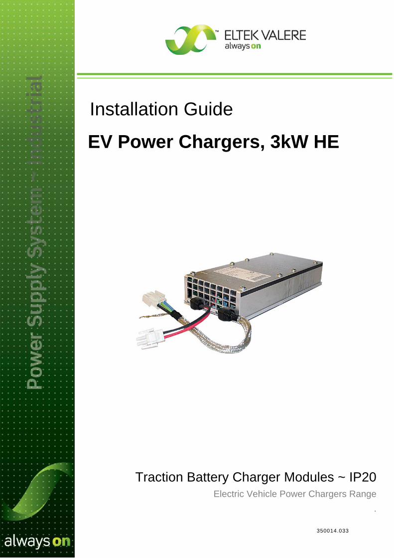
350014.033
Installation Guide
Traction Battery Charger Modules ~ IP20 Electric Vehicle Power Chargers Range
.
EV Power Chargers, 3kW HE
1 Installation EV Power Chargers, 3kW HE, IP20
2 Installation Guide EV Power Chargers, 3kW HE, IP20 350014.033, 1v1-2010-11
Information in this document is subject to change without notice and does not represent a commitment on the part of Eltek Valere. No part of this document may be reproduced or transmitted in any form or by any means — electronic or mechanical, including photocopying and recording — for any purpose without the explicit written permission of Eltek Valere.
Copyright ©: Eltek Valere, 2010
Safety Precautions The equipment represents an energy hazard and failure to observe this could
cause terminal injury and invalidate our warranty
There are hazardous voltages inside the power charger. As they incorporate large charged capacitors, it is dangerous to open the modules even if the mains supply is disconnected.
Products into which our components are incorporated have to comply with a number of requirements. Installation is to be in accordance with the recommendations herein
Please read the manual carefully before using the equipment This booklet describes following modules: Part no. Description 241121.010 EV Power Charger 110/3000 HE IP20 G2 241121.020 EV Power Charger 220/3000 HE IP20 G2 241121.030 EV Power Charger 360/3000 HE IP20 G2
350014.033 Issue 1.1, 2010 Nov Published 2010-11-04 Mafe
NS-EN ISO 14001 Certified
Certificate No: 11276-2007-AE-NOR-NA
NS-EN ISO 9001 Certified
Certificate No: 4072-2007-AQ-NOR-NA
1 Installation EV Power Chargers, 3kW HE, IP20
Installation Guide EV Power Chargers, 3kW HE, IP20 350014.033, 1v1-2010-11 3
Table of Contents
1. Installation EV Power Chargers, 3kW HE, IP20 4
Safety Precautions .......................................................................................................... 4 Mechanical Installation ....................................................................................................... 4
1. Prepare the Cold-Plate ............................................................................................... 5 2. Prepare the Battery Charger ....................................................................................... 6 3. Position and Fasten the Battery Charger .................................................................... 7
Electrical Installation .......................................................................................................... 8 CAN Bus Communication .................................................................................................. 9
Firmware Upgrade of the Battery Charger ................................................................................ 9
2. Technical Specifications 10
Specifications EV Power Chargers, 3kW HE, IP20 ....................................................... 10 Ordering Information ..................................................................................................... 10 Reference Documents .................................................................................................. 11

1 Installation EV Power Chargers, 3kW HE, IP20
4 Installation Guide EV Power Chargers, 3kW HE, IP20 350014.033, 1v1-2010-11
1. Installation EV Power Chargers, 3kW HE, IP20 Safety Precautions
Get acquainted with the satety precautions on page 2, before installing or handling the equipment.
Mechanical Installation
The EV Power Chargers, 3kW HE are designed in a very compact box measuring 49x280x120 mm.
The charger’s mechanical design implements thermal coupling, by mounting all internal major heat generating components against a solid aluminum outer wall.
The EV Power Chargers, 3kW HE must be fastened with this solid aluminum outer wall against a cold-plate, which is either water cooled or has sufficient heat transfer capacity to comply with the environmental specification of the installation site.
Also, the charger is to be housed to comply with the IP ratings required by the installation site.
Figure 1 Aluminum outer wall in the EV Power Chargers, 3kW HE **
WARNING: The cold-plate must have a heat transfer capacity of minimum 220W, keeping the charger at a lower temperature than 60ºC (output power derating level).
Figure 2 Mounting screws and dimensions for the EV Power Chargers, 3kW HE
** Refer to the photo on the cover page, for correct orientation of terminal wires.
Aluminum outer wall (thermal coupling)
EV Power Charger, 3kW HE
M5 fastening screws
Charger’s top
Device hazard
CAUTION: The battery chargers may be warm, but do not hand-carry them by the Multi-Crimp Terminal wires.
CAUTION: Double Pole / Neutral Fusing. There is a Mains fuse in each line.
Charger’s top
Hole diam. 5.30 x 8 (through-holes)
Fastenings screws 55 mm M5 x8
Multi-Crimp Terminal Wires
EV Power Charger, 3kW HE
All dimensions in mm
CAN Bus socket
49.0

1 Installation EV Power Chargers, 3kW HE, IP20
Installation Guide EV Power Chargers, 3kW HE, IP20 350014.033, 1v1-2010-11 5
1. Prepare the Cold-Plate The EV Power Chargers, 3kW HE must be mounted on a cold-plate, which is either water cooled or has sufficient heat transfer capacity to comply with the environmental specification of the installation site.
Prepare the cold-plate for mounting the charger, as follows:
Figure 3 Cold-plate preparations: drilling holes, cutting threads and applying thermal interface material
Cold-Plate Preparation Procedure — Steps Action OK
1. Clean the surface and apply a thermal interface material
• Thoroughly clean the cold-plate’s holes and the surface using rubbing alcohol (isopropyl alcohol) or pure acetone
• Apply a thin Thermal Interface Material (TIM) to the surface
Warnings: — The TIM should be a thermally conductive foil, for instance HALA TFO-X300-SI or similar, with 3 W/mK heat conductivity or better
Cold-plate M5 threaded hole
depth 8 mm x 8
Thermal Interface Material 1
1 Installation EV Power Chargers, 3kW HE, IP20
6 Installation Guide EV Power Chargers, 3kW HE, IP20 350014.033, 1v1-2010-11
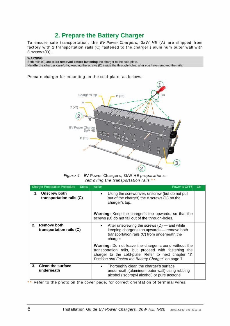
2. Prepare the Battery Charger To ensure safe transportation, the EV Power Chargers, 3kW HE (A) are shipped from factory with 2 transportation rails (C) fastened to the charger’s aluminum outer wall with 8 screws(D).
WARNING: Both rails (C) are to be removed before fastening the charger to the cold-plate. Handle the charger carefully, keeping the screws (D) inside the through-holes, after you have removed the rails.
Prepare charger for mounting on the cold-plate, as follows:
Figure 4 EV Power Chargers, 3kW HE preparations: removing the transportation rails **
Charger Preparation Procedure — Steps Action Power is OFF! OK
1. Unscrew both transportation rails (C)
• Using the screwdriver, unscrew (but do not pull out of the charger) the 8 screws (D) on the charger’s top.
Warning: Keep the charger’s top upwards, so that the screws (D) do not fall out of the through-holes.
2. Remove both transportation rails (C)
• After unscrewing the screws (D) — and while keeping charger’s top upwards — remove both transportation rails (C) from underneath the charger
Warning: Do not leave the charger around without the transportation rails, but proceed with fastening the charger to the cold-plate. Refer to next chapter “3. Position and Fasten the Battery Charger” on page 7
3. Clean the surface underneath
• Thoroughly clean the charger’s surface underneath (aluminum outer wall) using rubbing alcohol (isopropyl alcohol) or pure acetone
** Refer to the photo on the cover page, for correct orientation of terminal wires.
2
2
EV Power Charger 3kW HE
Charger’s top
A C (x2)
D (x8)
3
x8 D (x8) ccw
1

1 Installation EV Power Chargers, 3kW HE, IP20
Installation Guide EV Power Chargers, 3kW HE, IP20 350014.033, 1v1-2010-11 7
3. Position and Fasten the Battery Charger After preparing the cold-plate and the EV Power Chargers, 3kW HE for installation, fasten the charger to the cold-plate with the 8 screws(D), as follows:
Figure 5 Fastening the EV Power Chargers, 3kW HE to the cold-plate **
Charger Fastening Procedure — Steps Action Power is OFF! OK
1. Position the charger on the cold-plate
• Carefully position the charger’s bottom (aluminum outer wall) against the cold-plate, so that the 8 screws (D) meet with the threaded holes on the cold-plate
2. Fasten the screws (D) • Using the screwdriver, fasten the 8 M5 screws in the cold-plate’s threaded holes (torque 4 Nm)
NOTICE: The car manufacturer must carefully consider the need for additional spring washers or glue to secure the screws, in order to maintain a good contact between charger and cold plate/heat sink over time. Although long term vibration tests, performed on complete drive train inside a vehicle, have indicated that there should be no need for this, this may depend on the actual application. ** Refer to the photo on the cover page, for correct orientation of terminal wires.
A
D (x8)
EV Power Charger 3kW HE
Charger’s top
Fastenings screws 55 mm M5 x8 Torque: 4 Nm
1 Cold-plate
Thermal Interface Material
Hole diam. 5.30 x 8 (through-holes)
2
cw
x8
M5 threaded hole depth 8 mm
x 8
1 Installation EV Power Chargers, 3kW HE, IP20
8 Installation Guide EV Power Chargers, 3kW HE, IP20 350014.033, 1v1-2010-11
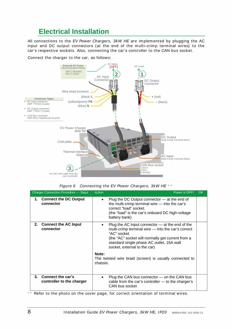
Electrical Installation All connections to the EV Power Chargers, 3kW HE are implemented by plugging the AC input and DC output connectors (at the end of the multi-crimp terminal wires) to the car’s respective sockets. Also, connecting the car’s controller to the CAN bus socket.
Connect the charger to the car, as follows:
Figure 6 Connecting the EV Power Chargers, 3kW HE **
Charger Connection Procedure — Steps Action Power is OFF! OK
1. Connect the DC Output connector
• Plug the DC Output connector — at the end of the multi-crimp terminal wire — into the car’s correct “load” socket. (the “load” is the car’s onboard DC high-voltage battery bank)
2. Connect the AC Input connector
• Plug the AC Input connector — at the end of the multi-crimp terminal wire — into the car’s correct “AC” socket (the “AC” socket will normally get current from a standard single phase AC outlet, 16A wall socket, external to the car)
Note: The twisted wire braid (screen) is usually connected to chassis.
3. Connect the car’s controller to the charger
• Plug the CAN bus connector — on the CAN bus cable from the car’s controller — to the charger’s CAN bus socket
** Refer to the photo on the cover page, for correct orientation of terminal wires.
EV Power Charger 3kW HE
Cold-plate DC Output Multi-Crimp Terminal Wires
CAN Bus socket CAN-H CAN-L CAN-Ref
AC Input Multi-Crimp Terminal Wires
Wire braid (screen)
AC Input Connector DC Output
Connector
(black) L (yellow/green) PE
(blue) N
+ (red)
– (black)
2
AC Mains (OFF)
3 For the CAN cable from the
car’s controller
Thermal Interface Material
1 DC Load
16A-C (Europe) 20A-C (USA)
External AC Fuses Recommended Rating
Connector Types • AC Input connector:
AMP 770018 (3-pole)
• DC Output connector: AMP 770017 (2-pole)
• CAN Bus connector: AMP Micro MateNLock (3-pole)

1 Installation EV Power Chargers, 3kW HE, IP20
Installation Guide EV Power Chargers, 3kW HE, IP20 350014.033, 1v1-2010-11 9
CAN Bus Communication The EV Power Chargers, 3kW HE utilize the CAN1
The EV Power Chargers, 3kW HE support CAN 2.0A/2.0B at the speed of 125, 250 and 500kbits/s, and implements CAN Bus signals: “CAN-L”, “CAN-H” and “CAN-Ref”.
bus a digital interface architecture that supports a dedicated communication channel between the car’s controller, the battery charger and other CAN devices or nodes connected to the bus.
The EV Power Chargers, 3kW HE are by default designed to be OFF, when connected to AC mains. To turn the chargers ON, they have to receive via the CAN bus a message containing voltage, current limit and power limit settings.
For prototype testing, Eltek Valere can provide a dedicated computer program for integration with the car electronics and the battery management system. Please, refer to the description of Eltek Valere’s CAN bus communication protocol, see chapter “Reference Documents” on page 11.
Firmware Upgrade of the Battery Charger Please, contact your Eltek Valere Local Office if you need to upgrade the chargers’ firmware, or if you need support with software integration.
1 Control Area Network. Serial protocol utilised for communication between CAN devices

2 Technical Specifications
10 Installation Guide EV Power Chargers, 3kW HE, IP20 350014.033, 1v1-2010-11
Applicable Standards Electrical safety IEC 61851-1
UL 2202 Compliant to IEC/UL 60950
EMC EN 61000-6-1 (immunity, light industry) EN 61000-6-2 (immunity, industry) EN 61000-6-3 (emission, light industry) EN 61000-6-4 (emission, industry)
Mains Harmonics EN 61000-3-2
Environment WDS 00.00EA-D11
Specifications are subject to change without notice 241121.nnn.DS3 – v3(b)
2. Technical Specifications
Specifications EV Power Chargers, 3kW HE, IP20
AC Input Voltage 85-275 VAC (Nominal 230VAC)
Frequency 45-65 Hz
Current 14 Arms maximum
Power Factor >0,99 at 50% load or more
Input Protection o Varistors for transient protection o Mains fuse in both lines
DC Output Voltage See table below
for adjustable voltage range **
Current See table below
Charge control: Controlled over CAN bus o Enable/Disable (On/Off) o Constant voltage o Current limit o Power limit o Available power (mains dependent)
Dynamic voltage regulation
±5% for 10-90% or 90-10% load variation, regulation time < 100ms
Ripple and Noise < 250 mVrms
Output Protection
o Output fuse o Overvoltage shutdown o Short circuit proof o High temperature protection o Under-voltage shutdown:
50V for *.010 & *.110 chargers, 110VDC 100V for *.020 & *.120 chargers, 220VDC 170V for *.030 & *.130 chargers, 360VDC
Other Specifications Efficiency 96% at 50% load, 95% at 100% load
Isolation o 1.5 KVAC – input to earth o 1.5 KVAC – output to earth o 3.0 KVAC – input to output
Alarms/error messages:
o Internal communication failure o Control system communication
timeout o High mains shutdown o Low mains shutdown o High temperature shutdown o Low temperature shutdown o Charger failure o DC voltage high (overvoltage
shutdown) o DC voltage low
Warnings: o Rectifier in power derate mode
Measurements: Available on CAN bus: o AC voltage, current and frequency o DC voltage and current o Rectifier temperature (two
measurements)
Operating temp -40 to 60°C
Storage temp -40 to +85°C (-40 to +185°F)
Cooling Cold plate
Reliability o MTBF > 162 000 hours, with 60°C cold plate temperature
Humidity o Operating: 5% to 95% RH non-condensing
o Storage: 0% to 99% RH non-condensing
Dimensions o 49x280x120mm (IP20)
Weight o 2.8 kg (IP20)
Ordering Information
Part no. Description Output Power Output Voltage Range Output Current 241121.010 EV Power Charger 110/3000 HE IP20 G2 3000W 70 – 122Vdc 25A 241121.020 EV Power Charger 220/3000 HE IP20 G2 3000W 150 – 250Vdc 16A 241121.030 EV Power Charger 360/3000 HE IP20 G2 3000W 250 – 420Vdc 10A
** Please, refer to technical specifications for further details

2 Technical Specifications
Installation Guide EV Power Chargers, 3kW HE, IP20 350014.033, 1v1-2010-11 11
Reference Documents
Doc no. Description 2090184 Technical specification EV PC 360/3000 HE IP20 2090186 Technical specification EV PC 220/3000 HE IP20 2090188 Technical specification EV PC 110/3000 HE IP20 2086930 EV Power Charger CAN protocol description

www.eltekvalere.com
Headquarters: Eltek Valere
Gråterudv. 8, Pb 2340 Strømsø, 3003 Drammen, Norway Phone: +47 32 20 32 00 Fax: +47 32 20 32 10