Embed Size (px)
Citation preview

© Euroheat Distributors (H.B.S) Ltd. 2000 Instructions Part number IN10111 Edition C1
Serial Number
Part No.
Technical Help LineFor Installation and Service AdviceTelephone 01885 4911178.30-12.30 and 1.30-5.30 Week daysFax 01885 491105 Anytime.Sales 01885 491111
Euroheat Distributors (H.B.S.) Ltd.,Unit 2, Court Farm Business Park,Bishops Frome,Worcestershire,WR6 5AY.01885 490474
Installation Instructions forHarmony 5
Wood and Coal Stove

© Euroheat Distributors (H.B.S) Ltd. 2000 Instructions Part number IN10111 Edition C2
INTRODUCTIONThe purpose of this technical document is to present, on the basis of the laws of physics involved, the importanceof the drawing power of chimneys and other factors on which the satisfactory functioning of wood & coal heatingequipment depends.
Modern building trends: small-sized rooms, sealed windows and door frames, high thermal output equipment, theobservance of health regulations and clean air fuel products require the whole problem to be reconsidered in itsentirety.
We manufacture a complete heating appliance which has to be connected to a chimney for normal operation. Thatchimney when being hot must be capable of providing the air necessary for combustion and fully evacuating thecombustion products.
The installer is responsible under the Health and Safety at Work Act 1974 vi the caustic nature of fire cement andthe possibility of disturbing asbestos in existing installations and to suggest appropriate protection to be given tothe person(s) carrying out the installation.
1) This appliance must be installed by a fully qualified heating engineer. He is responsible to ensure that theinstallation is in accordance with all currently accepted British Standards and Codes of Practice, particularly BS6461,CP403 and BS5449, relating to the installation of solid fuel appliances.
2) The stove must be placed at least 40cm away from any combustible materials. If necessary, any adjoining wallsshould be protected from the effects of heat.

© Euroheat Distributors (H.B.S) Ltd. 2000 Instructions Part number IN10111 Edition C3
Flue Outlet Options
Optional Front Facing Thermostat Indicator

© Euroheat Distributors (H.B.S) Ltd. 2000 Instructions Part number IN10111 Edition C4
D. Wind eddies or down-draughts around the top ofthe chimney, sometimes due to remote obstacles (hills,trees, houses, particular architectural arrangements, roofridge, etc.) may cause drawing problems.
E. Permanent or temporary excess drawing, alsoprejudicial to good combustion (buzzing noise), can becontrolled by a draught regulating flap when excessdraught is experienced at high flow settings. A draughtstabilizer is highly recommended as part of astandard installation.
F. In all cases the draught of the chimney must bemeasured with a draught indicator (gauge) connected tothe flue which runs from the stove to the chimney.The negative pressure indicated must ideally lie withinthe shaded zone on the requirement graph when thestove is operating smoothly.
ConclusionWhilst it is obvious that a chimney with adequate drawingpower alone will ensure the satisfactory functioning ofthe stove, it should never be forgotten that a largepercentage of problems are caused by faulty drawingpower of chimneys.
CHIMNEY DRAUGHTFor a wood/coal stove to operate normally, it is essentialthat the suction of the chimney, which determines theprovision of air to the stove, is continuous and that theevacuation of the fumes is ensured during combustion.That is why it is recommended, above all, to check thestate of the chimney to which the stove must beconnected. Once connected it is of the utmostimportance to balance the flue draught to conform thegraph showing draught requirements.
1. THE CHIMNEYIf the chimney is cold, the water in the flue gases willcondense. If it is porous the condensate will appear inthe form of unsightly brown patches on the externalwalls of the chimney.In the event of poor combustion an understanding ofthe paragraphs which follow will enable you to solve allthe problems.
A. In naturally aspirated wood/coal stoves the airnecessary for combustion is drawn into the combustionchamber by the negative pressure of the chimney. Thenegative pressure is uniquely due to the fact that thecombustion gases present in the chimney are hot andlighter than the air outside it. If the chimney is cold,either because it has not been used for a long time orbecause it has no heat insulation or is too short (minimum4 m), the slow air movement will prevent the flameburning cleanly. It is always necessary to wait for a whilewhen there is difficulty in operating until the chimneyhas warmed, before deciding that it is the chimney whichis at fault.
B. If inside the house, the stove chimney which is thenatural moving force of the combustion, is competingwith another stronger moving force (the entry ofsecondary air into the chimney, another higher or betterinsulated chimney, an extractor hood in the kitchen, awater-heater or a clothes dryer,...) combustion will bedifficult and in the most serious cases smoke and fumeswill even be drawn back into the house. If the house istoo well sealed and the air necessary for combustioncannot reach the stove, the same malfunction will occur.
In this case, it is not the chimney which is at fault, butthe fact that the room is too well sealed. This is easilyobserved by the following symptoms: the flame is weak,flickers or produces excess smoke. (responds slowly)The remedy consists of ensuring normal ventilation ofthe room in which the appliance is fitted.
This problem can be resolved, in particular, by bringingin the air necessary for combustion through a pipe ofadequate dimensions leading from outside the premisesclose to the stove. Like humans a stove has to breathe.
C. Any obstacle to the easy passage of the combustiongases through the chimney will be prejudicial to gooddrawing and therefore to satisfactory operation. Bends,turbulence, foreign bodies, dirt, nests, cold walls, etc.-see the cases shown in the appended diagrams.
A stable chimney draught within therequired parameters is always required.

© Euroheat Distributors (H.B.S) Ltd. 2000 Instructions Part number IN10111 Edition C5
Planning the chimney
A. The ideal chimney should be vertical, smooth, freeof cracks or foreign bodies. The chimney must be sweptbefore lining or connection.
Good Poor
B. To prevent throttling, suction cowls (chimney pots),or anti-down draught devices must not have a smallerconnecting section than the chimney.
2. The chimney and connection

© Euroheat Distributors (H.B.S) Ltd. 2000 Instructions Part number IN10111 Edition C6
D. Ceramic or pumice flue liners must be installed withsurrounding insulation. Ideally connecting flue pipeshould fit to the outside of the flue liner. All flueconnections must have the female socket facing upwards,male connection downwards.
E. It is unfortunately quite common to find that ceramic(clay) lined flues are installed with no insulation. Thiscan result in slow, poor operating chimneys which areinclined to cause condensation and other relatedproblems. In many cases the solution is to install a flexibleliner.
Good
Poor
C. The chimney outlets should be at least 1 m higherthan the roof ridge or the neighbour's wall. That is tosay that the chimney must not open into a pressure zone,i.e. between two buildings or under higher trees.

© Euroheat Distributors (H.B.S) Ltd. 2000 Instructions Part number IN10111 Edition C7
Good Poor
G. Rear flue connections should be fitted with a tee pipe,this allows a catchment area for falling soot and debris.
F. Connecting flue pipe must be joined to the chimneysystem above the point where the chimney narrows. Fluegases passing into void areas, turbulise, lose temperatureand so chimney draught.
Cleaning access options
Rear flue connection internal orexternal
Top flue connections internal only
Void
Soot,debris canblock flue
© Euroheat Distributors (H.B.S) Ltd. 2000 Instructions Part number IN10111 Edition C8
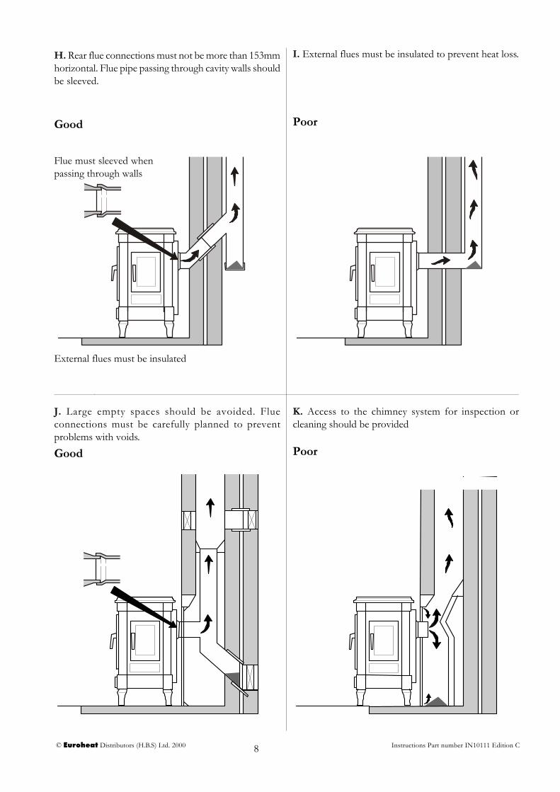
H. Rear flue connections must not be more than 153mmhorizontal. Flue pipe passing through cavity walls shouldbe sleeved.
I. External flues must be insulated to prevent heat loss.
Good Poor
J. Large empty spaces should be avoided. Flueconnections must be carefully planned to preventproblems with voids.
K. Access to the chimney system for inspection orcleaning should be provided
Good Poor
Flue must sleeved whenpassing through walls
External flues must be insulated

© Euroheat Distributors (H.B.S) Ltd. 2000 Instructions Part number IN10111 Edition C9
L. Prefabricated flues should be constructed so that theweight of the chimney is not supported on the stove.
M. In severe excess chimney draught conditions adraught stabilizer may be required.
Fitting Requirements
1. Stabilizer the same size as flue should be fitted.
2. The stabilizer should be at the end of a horizontalbranch of approximately 100mm.
3. The stabilizer should be fitted no closer than700mm to the flue outlet of the appliance.
4. The flue stabilizer should be fitted in the sameroom as the stove installation.
© Euroheat Distributors (H.B.S) Ltd. 2000 Instructions Part number IN10111 Edition C10
3. Chimney Cowls
1. Rain Ingress.To prevent rain penetration into the chimney system and stove. Damp chimney conditions result in poor and slowdraught. Water can also damage the stove especially during periods of none use.
2. Bird Prevention.Birds have the habit of building nests in chimney terminations. These endeavours often cause partial or completeblockage of the chimney system.
3. Down Draught Prevention.Down draughts are normally caused by poorly positioned flue terminations. It is a far better policy to change thechimney termination location by extension or redesign as severe down draughts will not be prevented by supposeddown draught cowls. In fact many assumptions of down draught are due to serious changes in the flue draughtcaused by wind variations on the termination position. (See stabilizer cowls ). However, there are cases where thehouse position, i.e., in a valley where down draughts cannot be prevented.
4. Flue Stabilization Cowls.The area of flue stabilization is one of the least understood. Wind movement across a chimney terminal can eitherdecrease the chimney upward movement “down draught” or more likely with a well designed chimney increase theupward pull by causing a venturi effect. The symptoms of change are asfollows:-
A. The flame becomes fierce and uncontrollable, reduced burning times,sooty glass in windy conditions.B. A roar or buzzing noise can be heard.To confirm this condition a flue draught reading should be taken.There are only a limited number of chimney cowls dedicated to fluestabilization. When sourcing a stabalizing cowel take great care. Manydown draught cowels will increase flue draught in windy conditions.
Air SupplyIf inside the house, the stove chimney which is the natural moving force of the combustion, is competing withanother stronger moving force (the entry of secondary air into the chimney, another higher or better insulatedchimney, an extractor hood in the kitchen, a water-heater or a clothes dryer,...) combustion will be difficult and inthe most serious cases smoke and fumes will even be drawn back into the house. If the house is too well sealed andthe air necessary for combustion cannot reach the stove, the same malfunction will occur.
Building Regulations require the provision for air supply.An air entry opening or openings with a total free area of at least 550mm2 per kW/hr of rated output above5kWhr.
Where a flue draught stabiliser is used the total free area should be increased by 300mm for each kW/hr of ratedoutput.
Chimney terminations have four basic areas of use.
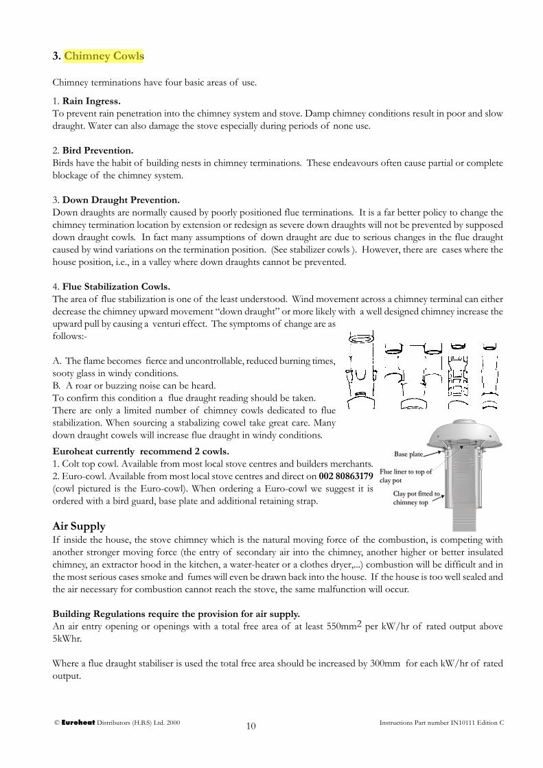
Euroheat currently recommend 2 cowls.1. Colt top cowl. Available from most local stove centres and builders merchants.2. Euro-cowl. Available from most local stove centres and direct on 002 80863179(cowl pictured is the Euro-cowl). When ordering a Euro-cowl we suggest it isordered with a bird guard, base plate and additional retaining strap.
Flue liner to top of clay pot
Clay pot fitted to chimney top
Base plate

© Euroheat Distributors (H.B.S) Ltd. 2000 Instructions Part number IN10111 Edition C11
Minimum Clearancefrom Inflammable
Materials
MinimumRequiredClearance
forOperation
A 18" 450mm 12" 300mm
B 16" 400mm 12" 300mm
C 12" 300mm N/A
D 16" 400mm 2" 50mm
E 16" 400mm 6" 150mm
A
B
D
C
E
F1
2/3 2/3
1/3 2/3
InstallationDo not be tempted to fit the stove into an unsuitable fireplace. Beyond the requirements of the building regulationsand access to facilitate servicing the stove, providing a setting which will compliment the Harmony is not a luxury,it is the practicality of making the most of an investment. A good builder will be able to transform even the mostutilitarian of fireplaces, whether altering its proportions to those of the “Golden Mean” ideal, exposing a woodenlintel, stone or simply removing superfluous detailing for comparatively small costs, and the result will be a pleasurefor many years.
Minimum installation clearances
Decorative plinth for Harmony 5
F = Decorative Hearth PlateSupplied as standard with Harmony 5
The measurements are for advice only. In allinstallations surrounding inflammable materialsmust not exceed 80oC. The stove must always standperfectly level and have sufficient space allowed forservice work.
F

© Euroheat Distributors (H.B.S) Ltd. 2000 Instructions Part number IN10111 Edition C12
5. Some Advice and Instructions
1) Question:What happens if the chimney flue descends to a lowerfloor (the cellar, for example)?Answer:The combustion gases involve some DEAD WEIGHTwhen mixed with a pocket of cold air. This will have aconsiderable detrimental effect on the drawing powerof the chimney.
Remedy:It is necessary to block the chimney with a metal sheetor concrete, etc. a few centimetres below the joint ofthe connecting pipe. Sufficient depth for a debris trapshould be provided.
2) Question:What happens if you wish to connect an appliance to achimney flue, to which another stove is alreadyconnected?Answer:This is prohibited under the U.K. building regulationsand should not be allowed.
3) Question:What happens when a chimney flue is excessively large?Answer:The combustion gases leaving the stove through a givensection expand suddenly, cool down and lose allascending force. The drawing power is, therefore, veryweak or non existent.
Remedy:The chimney must be lined to give it a more suitablesize.
4) Question:What happens if the flue draught is to low?Answer:The stove will be difficult to light, responding only slowlyto the demands of increased output and unable to reachits full heating output.
Remedy:a) Ensure there is enough free air to the stove.b) The flue is of a suitable size and is not obstructed.c) Consult installation instructions.
5) Question:What happens if there is to much flue draught?Answer:This can seriously damage the stove. An environmentcan be created akin to a Blacksmiths forge within thebody of the stove. Early signs of this is an uncontrolablefire, the glass crazing on the inside. Later signs are burnt,bent and buckelled cast iron internal stove parts.
Remedy:Ensure the stove is installed and commissioned as perthe installation instructions so that a flue draught test iscarried out prior to use. A flue draught stabaliser can befitted to the flue and a flue draught reading again taken.
6) Question:What do you do when a customer insists that theappliance be fitted in poor conditions?Answer:Poor conditions can only arise mainly due to the chimney.In this case the customer must be convinced thatmodifications are necessary. It is always preferable toabstain from taking action which will result in poorinstallation and so poor stove operation.
7) Question:Why must connecting flue pipes be inclined upwards?Answer:a) to prevent the gas from stagnating in the flue pipe;b) to prevent condensation by cooling off the gas;c) to prevent the sooting up of the pipes and the stoveitself.
8) Question:What should the degree of incline be?Answer:Given that the ideal chimney is vertical, angles shouldbe avoided as far as possible and the incline should be asclose to vertical as is practicable. The further away fromthe chimney the stove is placed, i.e., the more flue piperequired, the greater their incline should be.

© Euroheat Distributors (H.B.S) Ltd. 2000 Instructions Part number IN10111 Edition C13
To correctly commission the fully installed stove a flue draught measurement gauge will be required. This shouldbe sufficiently accurate to measure the negative pressure produced in the chimney system. If a flue stabilizer isfitted it should then be set in accordance with the graphic below, with the stove at maximum setting.
Commissioning
1. Adjusting thermostat setting
1mm
Thermostat adjustment screw
The cold setting of the thermostat must be checked before thestove is operated for the first time.
With the stove cold the gap between the inside left of thethermostat disc and the cast iron body of the stove should be1mm. at normal room temperature.
Note the thermostat disc is designed to close at a predeterminedangle.
firing rate
0.04
0.02
0.06millimetres inches
firing rate
2. Flue draught measurement
Flue draught measuredwith the air wash ventfully open and all otherair supplies to the fireclosed.
Euroheat can supply fluemeasurement gaugesorder number MS026.
Note this is not a watergauge used to measure
gas pressure.
.02
.01
.03
.04
.05
.06
.07.08.09
.05
.1
.2
.3
.4
.5
.6
.7
.8
.91.0
© Euroheat Distributors (H.B.S) Ltd. 2000 Instructions Part number IN10111 Edition C14
Flue Draught Measurement. cont
The negative pressure created within the combustion chamber of the stove must be measured using a test holedrilled into the flue, as close to the stove as possible and before any draught stabilizer that may be fitted to the flue.To ensure a constant air inlet size the readings should be taken with both the grate and the thermostatically controlledair inlet to the stove shut, and the secondary air-wash inlet fully open.
A reading should be taken before the stove is lit to identify any possible problems which may be caused by air beingdrawn down the flue by other heating appliances fitted with a flue, extraction fans, etc.. These should be dealt withbefore lighting the stove.
Once lit, the stove and flue should be allowed to warm thoroughly before letting the fire burn at a low setting.While taking the flue draught reading, all air entries to the combustion chamber of the stove should be closedexcept the secondary air-wash shutter, which should be fully open. The draught measurement should readapproximately 0.5mm gg.
The stove should now be made to burn at its maximum output and another draught measurement taken, againclosing all air supplies to the stove other than the secondary air-wash shutter. The draught reading when the burneris operating at its maximum setting should be approximately 1.5mm. gg.
A flue draught which is too low will result in the stove being difficult to light, responding only slowly to demandsfor increased output and unable to reach its full heating output.Flue draught which is too high will make control of the fire difficult, and makes it possible to over fire the stove,which can seriously damage it. In this instance a flue draught stabaliser may need to be fitted.
The installation manual should be consulted if the flue draught pressure readings are incorrect.
3. Operation and Lighting
The customer is to be advised about the operation and lighting procedures, use of the tools and general maintenanceof the stove.
4. Warranty
The warranty registration form should be completed and the user advised to return it fully completed to Euroheatfor registration.
5. Instructions
All instructions are to be left with the user.