Embed Size (px)
Citation preview
.390(10)
(6)
(8)
.235
.310
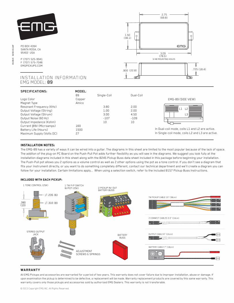
INSTALLATION INFORMATION EMG MODEL: 89
WarrantyAll EMG Pickups and accessories are warranted for a period of two years. This warranty does not cover failure due to improper installation, abuse or damage. If
upon examination the pickup is determined to be defective, a replacement will be made. Warranty replacement products are covered by this same warranty. This
warranty covers only those pickups and accessories sold by authorized EMG Dealers. This warranty is not transferable.
© 2013 Copyright EMG INC. All Rights Reserved.
PO BOX 4394
SANTA ROSA, CA
95402 USA
P (707) 525-9941
F (707) 575-7046
EMGPICKUPS.COM
02
30
-01
14
F
Installation notes: The EMG-89 has a variety of ways it can be wired into a guitar. The diagrams in this sheet are limited to the most popular because of the lack of space.
The additon of the plug-on PC Board on the Push-Pull Pot adds further flexibility as you will see in the diagrams. We suggest you look fully at the
installation diagrams included in this sheet along with the B245 Pickup Buss data sheet included in this package before beginning your installation.
The Push-Pull pot allows you 2 options as a volume control as well as 2 other options using the pot as a tone control. If you don’t see a diagram that
fits your instrument directly, or you want to do something completely different, contact our technical department and we’ll create a diagram you can
follow for your installation. Certain limitations apply... When using a selection switch, refer to the included B157 Pickup Buss Instructions.
SPECIFICATIONS: MODEL:
89 Single-Coil Dual-Coil
Logo Color Copper
Magnet Type Alnico
Resonant Frequency (KHz) 3.80 2.00
Output Voltage (String) 1.00 2.00
Output Voltage (Strum) 3.00 4.50
Output Noise (60 Hz) -107 -109
Output Impedance (Kohm) 10 10
Current @9V (Microamps) 160
Battery Life (Hours) 1500
Maximum Supply (Volts DC) 27
OUTPUT CABLE 6” (15cm)
2 CONNECT CABLES 5.5” (14cm)
BATTERY CABLE 7” (18cm)
B245
B1
36
rE2.75
1.50
3.09
3/48 MOUNTING HOLES
.900.725
(69.8)
(38.1)
(22.8) (18.4)
(78.5)
- 9V +
BATTERY
BUSS
STEREO OUTPUT
JACK
1 TONE CONTROL (25K)2 PICKUP IN/ OUTBATTERY BUSS
ADJUSTMENT
SCREWS & SPRINGS
EMG-89 (SIDE VIEW)
In Dual-coil mode, coils L1 and L2 are active.
In Single-coil mode, coils L2 and L3 are active.
L1 L2
L3
TW PICKUP CABLE 15” (38cm)
Included with each pickup:
1 TW P/P SWITCH
W/POT (25K)

89 INSTRUCTIONS Page 2
Using the Pot Section as:
1) The Pickup Volume control, or a Master Volume for the Instrument.
Refer to Diagrams #3 and #4
The pot section (25KA) can be used either as a Volume control
for the pickup or, it can be used as the Master Volume for the guitar.
Diagrams #3 and #4 show how to connect either option.
Use the dual-line 12-pin header and push the cables on and
install the shunts as needed onto the labeled headers H1 thru H6.
Use Diagram #3 if you have a single TW installed in your instrument,
or have two or more pickups in your instrument and want to use the
pot as the Volume control for the TW Pickup only.
Installing the shunts on positions H4 and H6 sends the pickup signal
to the wiper of the 25K Pot, and the output of the 25K Pot is at position
H1 or H2.
Diagram #4 allows you to use the 25K Pot independently of the pickup output.
By taking the output of the pickup from position H5, the Volume control is now
available to use as a Master Volume with H1 or H2 being the input to the Volume
control. H1 and H2 positions are interchangeable.
Position H5, now the output of the pickup, would typically go to a selection switch
or a pan-pot. Don’t forget to install the shunt on H6.
Using the TW Push-Pull Pot SectionThe Push-Pull Pot side of the EMG-TW allows you 4 different options:
1) Use the pot as a Master Volume for the Instrument
2) Use the pot as a Volume control for the TW Pickup
3) Use the pot as a Master Tone control for the Instrument
4) Use the pot as a Tone control for the TW pickup
On the PC Board there is a dual-line header with 6 pairs of pins. They are
listed on the PC Board as H1 through H6. By using the the connections
shown in Diagrams #3 through #6, you can choose any of the 4 options.
General Notes:
Every attempt has been made to make this a solderless installation.
There are some instances where this is not possible;
1) If your instrument uses the long panel output jack and you had passive pickups
you will need a new stereo output jack, the Switchcraft 152B is recommended.
Soldering to the new jack will be required.
2) Some instruments may already have a battery holder installed, in that case
soldering may be required.
3) Instruments with two pickups may need soldering to the selection
switch in some installations.
Using the TW Push-Pull SwitchThe Push-Pull Switch included with the TW Pickup allows you to choose between
two internal pickups of the EMG-TW, single-coil and dual-coil. The Push-Pull Pot
has two seperate sections: The Switch and the pot, described below.
Refer to Diagrams #1 and #2
The Push-Pull Switch section (DPDT) lets you choose between the
single-coil sound and a dual-coil sound by pulling or pushing the pot shaft
up or down. You have the option of having the single-coil sound in either
the up or down position and vice-versa for the dual-coil sound.
Diagrams #1 and #2 show how to connect the TW Pickup cable to choose
either option. Select the diagram that suits you and push the cable
connectors onto the single line 6-pin header.
Simply turn over cable connectors 1 and 2 to change the wire order
and this will choose between the two options.
Connector 3 remains the same for either choice.
Diagram #1
HUMBUCKING ON: DOWN POSITION
SINGLE COIL ON: UP POSITION
Diagram #2
SINGLE-COIL ON: DOWN POSITION
HUMBUCKING ON: UP POSITION
FLIP CONNECTORS 1 AND 2
AS SHOWN
WIRE ORDER:
WHITE
GREEN
BLUE
YELLOW
ORANGE
SHIELD
WIRE ORDER:
GREEN
WHITE
YELLOW
BLUE
ORANGE
SHIELD
SHUNT ON (H6)
PICKUP OUTPUT (H5)
MASTER VOLUME
OUTPUT (H3)
MASTER VOLUME
INPUT (H1 OR H2)
Diagram #4
PUSH / PULL POT USED AS
THE MASTER VOLUME CONTROL
TO SELECTION SWITCH
(VIA B245 BUSS)
OR PAN-POT
PICKUP OUTPUT
(H1 or H2)
INSTALL SHUNT (H6)
INSTALL SHUNT (H4)
1
2
3
1
2
3
Diagram #3
PUSH / PULL POT USED AS
THE PICKUP VOLUME CONTROL
OR TO THE OUTPUT JACK IN SINGLE
PICKUP GUITARS WITH NO TONE
CONTROL
PICKUP OUTPUT:
TO TONE CONTROL OR
SELECTION SWITCH OR BUSS
FOR 2 OR 3 PICKUP GUITARS
B136rE

89 INSTRUCTIONS Page 3
B124rH
TONE
Diagram #7
Insert the plug onto the 7 pin header
of the pickup as shown above.
Note the orientation arrow.
Diagram #9
One TW Pickup
Master Volume and Tone Control
Diagram #8
One TW Pickup
Master Volume
Using the Pot Section as:
2) The Pickup Tone control or as a Master Tone control for the instrument.
Refer to Diagrams #5 and #6
The pot section (25KA) can be used either as a Tone control
for the pickup or it can be used as a Master Tone control for the guitar.
Diagrams #5 and #6 show how to connect either option.
Use the dual-line header, push the cables on and install the shunts
as needed onto headers H1 thru H6.
Use Diagram #5 if you have a single 89 installed in your instrument,
or have two or more pickups in your instrument and want to use the pot as the
Tone control for the 89 Pickup only.
Installing the shunt on position H4 connects a tone capacitor on the PC Board
to the wiper of the 25K Pot and creates a passive Tone control. The output of
pickup can be either position H1 or H2.
Diagram #6 uses the 25K Tone control independently of the pickup output.
By taking the output of the pickup from Position H5, the control is now
available to use as a Tone Control independent of the pickup output.
Position H3 is the input to the Tone Control, with H1 or H2 being the output of
the control, if necessary.
Position H5, the output of the pickup, would typically go to a selection switch
or output jack.
OUTPUT
T
R
S
BATTERY
NEG (-)
RED
RED
BATTERY
BUSS
PICKUPVOLUMECONTROL
MASTER TONE
OUTPUT
T
R
S
BATTERY
NEG (-)
RED
RED
BATTERY
BUSS
PICKUPVOLUMECONTROL
PICKUP OUTPUT:
TO VOLUME CONTROL
SELECTION SWITCH OR...
PICKUP OUTPUT
(H1 or H2)
INSTALL SHUNT ON (H4)
OUTPUT OF TONE CONTROL
(H1 or H2) ONLY IF NEEDED
INPUT TO TONE CONTROL (H3)
PICKUP OUTPUT
(H5)
- 9V +
- 9V +
PICKUP OUTPUT TO
SELECTION SWITCH,
EMG ACCESSORY, OR...
Diagram #5
PP POT USED AS THE PICKUP
TONE CONTROL
Diagram #6
PUSH-PULL POT USED AS A MASTER
TONE CONTROL
FROM PICKUP
FROM PICKUP

89 INSTRUCTIONS Page 4
TONE
B124rH
MASTER
TONE
BRIDGE PICKUP
BATTERY
NEG (-)
T
R
S
RED
RED
RED
GROUND
BRIDGE P/U
NECK P/U
OUTPUT
- 9V +
GROUND
BRIDGE P/U
NECK P/U
OUTPUT
Refer to Diagram #10 Above:
1) Install the Pickups and route the cables to the control cavity keeping
any excess cable under the pickup.
2) Choose an up/down option from Diagram #1 or #2 and plug the 89
Pickup cable onto the push-pull pot.
3) Route a coax cable from the push/pull pot (H4) to the Pickup buss, Position 1.
Plug the pickup cable of the other EMG into Position 2 of the pickup buss.
4) Plug a coax cable from Position 3 of the Pickup Buss to the Tone control.
Plug a coax cable from the Tone control to the Push-Pull Pot (H1)
5) Plug the output cable from the Push-Pull Pot (H2) to the output jack and push
the connectors onto the T, S, and R terminals of the jack as shown.
6) Plug the RED Wires of the pickups onto the V+ Supply Buss (RED Shroud)
with the RED wire of the battery clip.
7) Strip the insulation from the switch wires and Insert them into the GREEN
and BLACK Terminal Blocks and tighten the screws with a small screwdriver.
Refer to the B157 Pickup buss instructions enclosed.
8) Put the battery in the insulating foam piece provided and place it securely in
the control cavity.
We suggest that you plug in the instrument and test it before closing the
control cavity.
Refer to Diagram #11 Below:
1) Install the 89 Pickups and route the cables to the control cavity keeping
any excess cable under the pickup.
2) Choose an up/down option from Diagram #1 or #2 and plug the 89 Pickup
cables onto the push-pull switch sections.
3) Route a coax cable from each of the Push-Pull Pots (H1) to the Tone controls.
4) Plug a coax cable from the Bridge Tone to the Pickup Buss (Position 1)
Plug a coax cable from the Neck Tone to the Pickup Buss (Position 2)
5) Plug the output cable from the Pickup Buss (Position 3) to the output jack and
push the connectors onto the T, S, and R terminals of the jack as shown.
6) Plug the RED Wires of the pickups onto the V+ Supply Buss (RED Shroud)
with the RED wire of the battery clip.
7) Strip the insulation from the switch wires and Insert them into the GREEN
and BLACK Terminal Blocks and tighten the screws with a small screwdriver.
Refer to the B157 Pickup buss instructions enclosed.
8) Put the battery in the insulating foam piece provided and place it securely in
the control cavity.
We suggest that you plug in the instrument and test it before closing the
control cavity.
Diagram #10
2 Pickups (1 EMG / 1 EMG-TW)
Toggle Style Select Switch
Push-Pull Pot as Master Volume
with a Master Tone (Passive)
NECK EMG-TW PICKUP
OUTPUT CABLE
MASTER
VOLUME
Diagram #11
2 TW Pickups
2 Push-Pull Pots as Volume controls
(Volumes are independent)
2 Tones (Passive)
Toggle Style Switch
- 9V +
T
R
S
OUTPUT
BATTERY
NEG (-)
RED
RED
RED
OUTPUT CABLE
NECK
VOLUME
EMG-TW PICKUP (NECK)
BRIDGE
VOLUME
EMG-TW PICKUP (BRIDGE)
B124rH
TONE
BRIDGE TONE
B124rH
TONE
NECK TONE