Embed Size (px)
Citation preview

Installation & Instruction ManualAll Residential & Small System Models
(except EZ95)
RadonAway3 Saber Way Ward Hill, MA 01835
radonaway.com
IN063 Rev. B 0713

Page 2 of 24IN063 Rev. B 0813
1. PRE-INSTALLATION............................................................................................................ 3 1.1.SafetyMatters........................................................................................................................................................................3 1.2.WaterFlowRequirements...................................................................................................................................................4 1.3.UnpackingandLocatingSystemComponents..................................................................................................................5 1.3.1.UnpackAllSystemComponents..................................................................................................................... 5 1.3.2.LocateAllComponents......................................................................................................................................5 1.4.UseQualifiedTechnicians...................................................................................................................................................5 1.5.FullWaterTest......................................................................................................................................................................5
2. INSTALLATION INSTRUCTIONS.....................................................................................6 2.1.SystemLocation....................................................................................................................................................................7 2.2.ReadyingtheAIRaiderTMforInstallation..........................................................................................................................7 2.3.PlumbingHook-up...............................................................................................................................................................9 2.4.ElectricalHook-up.............................................................................................................................................................112.5.VentLineInstallation.........................................................................................................................................................16 2.6.RemoteAirIntake..............................................................................................................................................................17 2.7.SystemStart-up.................................................................................................................................................................18 2.8.SystemCheck.......................................................................................................................................................................19
3. RETESTING..............................................................................................................................20
4. MAINTENANCE...................................................................................................................20 4.1.SixMonthService(recommended)..................................................................................................................................20 4.2.AnnualService(required)..................................................................................................................................................21
5. TROUBLE SHOOTING........................................................................................................22
LIMITED WARRANTY.............................................................................................................23
APPENDICES A.1.PumpSpecification,433-S50Systems,pumpmodel20DOMO5121+1...............................................................insert
Figure 1 a,b,c-TypicalSystems(433-S,433,321)..................................................................................................................................6Figure 2 -Pump&BypassAssembly(433/321)....................................................................................................................................7Figure 3-InstalledSystem(433,321)......................................................................................................................................................8Figure 4-PlumbingInstallation(433-S50).............................................................................................................................................9Figure 5-PlumbingInstallation(433-S50X)........................................................................................................................................10Figure 6-WiringDiagram433115V/230V............................................................................................................................................12Figure 7-WiringDiagram433S50/115V..............................................................................................................................................13Figure 8-WiringDiagramS50X/115V..................................................................................................................................................14Figure 9-WiringDiagram321/115V.....................................................................................................................................................15Figure 10-VentLineConnection..........................................................................................................................................................16Figure 11-VentLineInstallation(2inch)............................................................................................................................................16Figure 12-VentLineInstallation(3inch)............................................................................................................................................16Figure 13-AirFilter................................................................................................................................................................................17Figure 14-AirIntakeConnection.........................................................................................................................................................17Figure 15-InstalledAIRaiderTM(433-S50)...........................................................................................................................................18
Table of Figures
TABLE OF CONTENTS & FIGURES

Page 3 of 24IN063 Rev. B 0813
1. Pre-InstallationTheAIRaiderTMSystemsarediffusedbubbleaerationsystemsfortheremovalofradonandotherVOC’sfromresidentialandmunicipalwatersupplies.Thisinstallation/operationmanualisdesignedtoguideprofessionalsthroughthesafeandproperinstallationoftheAIRaiderTM Systems.
BeforebeginningtheinstallationoftheAIRaiderTMSystem,thereare5itemstobeconsidered.Theyare: 1. Safety 2.InstallationSiteRequirements 3.InspectionofSystemComponents 4.NecessityforQualifiedTechnicians 5.KnowledgeofallContaminantsintheWater
1.1. Safety Matters
Safetyisthemostimportantstepintheinstallationprocess.Neverperformanystepoftheinstallationthatyouarenotqualifiedtoperform(i.e.Electricalorplumbinghookup).Itisimportantthatyoureadthroughtheentiremanualpriortobeginningtheinstallation.Whenperformingtheinstallation,workslowlyanddeliberately.Followallinstructionscarefullyandnevertakeshortcuts.Ourteamoftechniciansisavailabletoansweryourquestionsat800-355-0901.
WORK SAFELY!
PRE-INSTALLATION1
Page 4 of 24IN063 Rev. B 0813
1.2. Water Flow Requirements
ThestandardresidentialAIRaiderTMSystemsaredesignedforusewithwaterflowsupto20gallonsperminute(GPM).*Thesystemcomesequippedwithanoutflowballvalve.Ifhigher/lowersystemoutflowisneeded,open/closetheballvalvebytheamountnecessarytobalancethesystem.Thewellpumpoutputmustproduceatleast1GPMmorethantheoutputoftheAIRaiderTM(i.e.welloutput=8GPM;AIRaiderTMoutflowsetting=7GPM)forpropersystemperformance.IfthewellpumpoutputislessthanthesystemoutputtheAIRaiderTMwillrundryandpossibledamagemayoccur.Topreventthisfromoccuringthewaterflowratemustbedeterminedbeforethesystemisinstalled.*Some AIRaiderTM Systems are not recommended for high flow residential properties. All repressurization systems (except for the AIRaiderTM EZ95,433-S50 & 433-S50X) are sold separately. Proper repressurization system sizing is required to meet water flow needs. Consult manufacturer if assistance is needed for system selection.
Inordertodetermineavailablewaterflowratethefollowingisneeded: •GardenHose •Five-GallonBucket •AStopWatchorWatchwithaSecondHand Or •AWaterFlowMeter
Household water use must be discontinued during the following flow rate test.
Mid-Range Flow Rate Test:
1.AttachgardenhosetothedrainconnectiononthebaseoftheWellPressureTank.
2.Openthedrainvalveandrunwaterfor15minutes.
3.After15minutes,checkthepressuregaugeonthewellsystem.Adjustthedrainvalve(openor close)asneededtomaintaintherequiredrunningsystempressure(constantpressureongauge)withthewellpumprunningcontinuously. 4.Runfor5minuteswhileensuringthatthepressureisnotfluctuating.
5.Runwaterfromthehoseintoafivegallonbucket.Usingastopwatch,timehowmanysecondsittakestofillthebucket(Zsec.).
6.DeterminetheGPMbydividing60secondsbythenumberofsecondsittooktofillthebucket(Zsec.).Multiplytheanswerby5gallons.ThisgivesyoutheGPM. GPM = ( 60 / Z ) x 5
7.Repeatsteps5and6andaveragethe2numbers.Theansweristhewellpumpoutputingallonsperminute.Itisrecommendedthatthisnumberbeindeliblyrecordedinanobviouslocation,togetherwiththedateoftest,asitwillberequiredwhensettingtheAIRaiderTM System and may berequiredforfuturetroubleshootingofthewellpumpsystemortheAIRaiderTM System.
PRE-INSTALLATION1

Page 5 of 24IN063 Rev. B 0813
1.3. Unpacking and Locating System Components
1.3.1. UnpackAllSystemComponents Removeallpackingmaterialanddiscardappropriatelyawayfromtheworkarea. 1.3.2. LocateAllComponents Checktoensureallcomponentsareintactandincludedinshipment.(SeeFigure5and8) Includedcomponentlist(mayvarywithorder): •TankAssemblywithSolenoidAssembly •ControlPanel*andFloatSwitches •SubmersiblePump** •JetPumpandBladderTankAssembly*** •Brass–BypassAssembly,PumpBrass,andTankBrass**** •InstallationKit–Manual,PressureGauge,etc.
*Model321doesnotcomeequippedwithacontrolpanel **Mountedinternallyon433-S50and433-S75Systems,notsuppliedwith433and321Systems. ***Pumppackagesaresoldseparatelyon321and433Systems,andwillvarywiththeorder. BladderTanksaresoldseparately. ****Soldseparatelyon321and433Systems.Standardsystemsareequippedfora¾”plumbingconnection.1”plumbingconnectionisavailableon433Systemsonly(Not433433-S50or433-S75).Pleasespecifyplumbingconnectionrequirementswhenordering. BypassAssemblyisintegralon433-S50SystemsOnly.
1.4. Use Qualified Technicians
ALicensedPlumber,Electrician,Contractorand/orCertifiedWaterTreatmentSpecialistmayberequiredtoinstalltheAIRaiderTMSysteminaccordancewiththeinstallationinstructions.AllwiringmustbeperformedinaccordancewiththeNationalFireProtectionAssociation’s(NFPA)”NationalElectricalCode,Standard#70”-currenteditionforallcommercialandindustrialwork.Allwiringmustbeperformedbyaqualifiedandlicensedelectrician.CheckyourLocalandStateCodeandLicensingrequirements.Failuretofollowtheinstructionsmayleadtopoorsystemperformanceand/orpossiblesystemdamage.
The Installation must comply with all applicable Local and State Codes and NFPA National Electrical Code, Standard #70!
1.5. Full Water Test
AfullWaterSampleAnalysismustbeperformedtodeterminethequalityofthewaterthatrequirestreatment.Inmanywatersupplies,contaminantsotherthanradonarepresentandmayneedtobepre-treatedinorderfortheAIRaiderTMtoworkproperly.TheAIRaiderTMSystemisonlyeffectivefortheremovalofradonandsomeotherVOC’s.TheAerationProcessemployedbytheAIRaiderTM Systemandotherradonremovalsystemscanworsenproblemsduetoironormanganesecontaminantsinthewatersupply.ForoptimalremovalofradonorotherVOC’s,othercontaminantssuchasiron,ormanganesemustberemovedbeforethewatersupplyenterstheAIRaiderTM System.
Failure to remove other contaminants can reduce the effectiveness of the system and may result in system damage!
PRE-INSTALLATION1

Page 6 of 24IN063 Rev. B 0813
2. Installation InstructionsOVERVIEW
Nowyouarereadytobegintheinstallationprocess.TheeightstepstoproperlyinstalltheAIRaiderTM Systemarelistedbelow.Readallcomponentsofeachsteppriortobeginningtheactualinstallation.
1.SystemLocation 2.ReadyingtheSystemforInstallation 3.PlumbingHook-up 4.ElectricalHook-up 5.VentLineInstallation 6.RemoteAirIntakeInstallation 7.SystemStart-up 8.SystemCheck
SAFETY TIP: Do Not undertake any step for which you are Not Qualified.
Figure 1 a,b,cTypicalSystem
(RepressurizationSystemsnotshown,soldseparatelyon321,433and433-1)
433-S50 321433 & 433-1
INSTALLATION INSTRUCTIONS1 2

Page 7 of 24IN063 Rev. B 0813
2.1. System Location
WhenselectingthelocationfortheAIRaiderTMSystem,fivefactorsshouldbeamongthoseconsidered: 1. SystemPlumbingHook-up.Findalocationthatwillminimizetheamountofplumbing necessary,thisistypicallyinproximitytothewelltank. 2. ElectricalHook-up.Keepinmindtheneedforaccessibilitytoa20Ampdedicated120VAC powersupplyor30Ampdedicated230VACfor230V433Systems. 3.ExhaustLineVenting.Thelocationofthesystemmustallowforoutsideventingofthesystemexhaustabovetheeaveofthestructure.Themanufacturerrequiresthattheexhaustpipepitchbacktowardthesystem(seeSection2.6). 4.RemoteAirIntake.Ifthesystemmustbeinstalledinanareawithquestionableairquality (i.e.furnaceroom,garage,crawlspace)thenductingfromtheairintaketoaremotelocation havinggoodairqualitymayberequired. 5. SystemMustBeLevel.Thesystemshouldnotbelocatedonasignificantslopeasthismay impedesystemperformance.
Placethesysteminthelocationacceptabletocustomerthatmaximizestheeaseofinstallation.AllLocalandStatecodesaswellasanyapplicableAARST,EPAand/orStateRadonstandardsmustbeadheredtowhenlocatingtheAIRaiderTM(i.e.awayfromelectricalpanel,furnace,exits,etc.).
2.2. Readying the AIRaiderTM for Installation For 433 and 321 systems (433 Illustrated). This section does not apply to Systems with integral pumps (433-S50 & 433-S50X Systems).
1.IfusingtheGrundfosMQ3-45PumpattachMount-ingBrackettowallasshowninFig.3(page8).NotebracketholeheightisspecifictotheGrundfosMQ3-45.IfusingadifferentpumpadjustbracketheightasrequiredtoplacepumpsuctionpipecenterlineatthesystemoutletcenterlineasspecifiedinFig.3.Note: Short horizontal pipe run from system outlet to pump inlet is optimal. If this pump location is impractical because of space constraints the pump may be located remotely at a higher location, but pump lift, pipe diameter, and equivalent pipe length must comply with limits specified in the pump installation instructions.
Do not mount pump lower than shown as removal of the pump for service may result in tank contents siphoning out onto the floor!
2.InstalltheSuctionCheckValveprovidedwiththeGrundfosMQ3Pumpintothepumpinletasshowninthepumpinstallationinstructions.Thiswillpreventlossofpumpprimeandpossibleinterruptionsinthewatersupplytothehouse.Removetheprimingplugfromthepumpandaddthespecifiedvolume(SeePumpInstallationInstructions)ofwatertothepump.Eitherre-installtheprimingplugorinstalla⅜”NPTx2”longpipenippleandattacha¼”NPTPressureGaugewithwith¼”x⅜”FNPTReducertothepipenipple(Fig.2).
Figure 2 Pump&BypassAssembly
INSTALLATION INSTRUCTIONS1 2

Page 8 of 24IN063 Rev. B 0813
3.Sitthepumpontothemountingbracketandconnectpumpinlettosystemoutlet.Thesystemoutletisprovidedwitha¾”SharkbiteConnectionsuitablefor¾”NominalCopperTubeorPexTube;insertionlengthintoSharkbiteFittingis1”.Additionalfittingswillberequiredtoconnectthetubetothe1”MNPTthreadedconnectionontheMQ3-45Pump.Fittingsrequiredmayvarywithpumpused.Cutthetubingtothelengthrequiredtoalignthepumpbasewiththemountingholesinthepumpmountingbracket.Boltthepumptothemountingbracket.
4.WiththeSystemlocatedasdesired,installthepipe/tubefromthepumpdischargetothedesiredlocationofsupplytohouse.AtthehouseendateeisrequiredtoaccommodatesupplytohouseandtoSystemBypassConnection.Fittingswillberequiredtoconnecttothe1”MNPTthreadedconnectionontheMQ3-45Pump.Fittingsrequiredmayvarywithpumpused.TheoptionalBladderTankhasa¾”MNPTthreadedconnection.Ateewillberequiredifthebladdertankisinstalled,otherwiseanelbowmaybeusedatthesamelocation.Tofacilitateremovalofpumpforservice,aquickdisconnect(sharkbiteasillustrated,orpipeunion)isrecommendedonthepumpsideoftherequiredSystemOutletValve(normallyopenballvalve).
5.Installpipe/tubefromSysteminlet(Fig.2)tothedesiredlocationofthesupplyfromthewelltank.Atthesupplyendateeisrequiredtoaccommodatesupplyfromthewellandthesystembypassconnection.Thesysteminletisprovidedwitha¾”SharkbiteElbowsuitablefor¾”NominalCopperTubeorPexTube,insertionlengthintoSharkbiteFittingis1”.ASystemInletValve(normallyopenballvalve)isrequiredbetweentheteeandSharkbiteElbow.
6.Installthepipe/tubebetweentheteesatthedesiredlocationsofthesupplytohouseandthesupplyfromwell.ASystemBypassValve(NormallyClosedBallValve)isrequiredbetweenthetees.
Figure 3 Installed433NDSystem
INSTALLATION INSTRUCTIONS1 2

Page 9 of 24IN063 Rev. B 0813
2.3. Plumbing Hook-up
All Plumbing should be performed in accordance with Local and State Codes by a Qualified Plumber.
1.Shutoffthewatermainvalvelocatedafterthepressuretank.
2.Drainthewaterline.
3.Plumbthesystemintothewaterlineafterthepressuretankandallotherwatertreatmentequipment.
4.PlumbthewaterlinefromtheexistingpressuretankintotheInletTee.
5.PlumbthewaterlinetothehouseintotheOutletTee(Fig.2,4or5dependingonSystemandPump).Aflowrestrictororgatevalveinthewaterlinetothehouseisrequiredforbalancingthesystemflow.ABladderTank,minimumcapacity5gallonsisrequiredfor433-S50Systems(20gal.min.for433-S50X).WARNING: Bladder Tank must be supported by hanger attached to wall or joist.
6.MakingsuretheBypassvalveisopenandInletandOutletValvesareclosed,slowlyopenthewatermainvalveandcheckforleaks.
7.Slowlychangebypasstothe“service”configuration,Bypassvalveclosed,inletandoutletvalvesopen.PrimejetpumpasperManufacturersInstructions(SeeenclosedJetPumpManual)ifnotpreviouslyprimed.Notethatintegralpumpon433-S75and433-S50systemswillselfprimewhenthesystemtankisfilled.
Figure 4 PlumbingInstallation433SNDSystem
INSTALLATION INSTRUCTIONS1 2

Page 10 of 24IN063 Rev. B 0813
INSTALLATION INSTRUCTIONS1 2
Figure 5PlumbingInstallation433-S50X

Page 11 of 24IN063 Rev. B 0813
2.4. Electrical Hook-up
All Electrical Work should be performed in accordance with Local and State Codes, and NFPA National Electrical Code, Standard #70 by a Qualified and Licensed Electrician .
WARNING: Never perform electrical work while standing in water. Do not attempt wiring on a live circuit.
WARNING: Power Supply Voltage must match the voltage marked on the System Nameplate. Improper wiring may result in system damage.
1.Turnmainpowerswitch,locatedontheAIRaiderTM,tothe“Off”position.
2.ConnecttheJetPumppowercordtotheJetPump.(DoesnotApplyto433-S50or433-S50XSystems,pumpisfactoryconnected)NotetheJetPumppowercordfromtheAIRaiderTMisprovidedwithanelectricalreceptacle.TheJetPumpmaybeconnectedeitherbyconnectingasuitablepowerleadwithplugandpluggingintothereceptacleorbyremovingthereceptaclefromtheJetPumppowercordandconnectingthepowercorddirectlytothepump.FollowwiringinstructionslocatedintheenclosedJetPumpManual.
Warning: Never remove the Receptacle from the Jet Pump Power Cord without connecting the wires thus exposed to the jet pump, inside the Jet Pump Electrical Enclosure. Always secure the Jet Pump Enclosure Cover after making electrical connections.
3.On433-S50XunitsonlytheinstallermayneedtodisconnecttheArmoredCablesuppliedinordertoinstallthePressureSwitch.TheArmoredCablemayrequiretrimmingtothedesiredlengthbeforereconnecting.ConnectperthewiringdiagramFigure8Page14.
4.Makesureallconnectionsinthecontrolpanelaretight.
5.Bringinpowertothecontrolpanelusingtheholeprovided,eitheranappropriatestrainreliefbushing,orelectricalconduitfitting(s),withcorrectlyratedelectricalwireorcablemustbeusedinaccordancewithallapplicableElectricalCodes.
6.Connectthepowerlinetothecontrolpanelasshownintheapplicablewiringdiagram(SeeFigures6,7,8,9-onpages12-15).
7.Connectpowerlinetopowersource*.TherequiredVoltageiseither120Vor240Vandisindicatedbyan“X”markedinthecheckboxnexttoeitherthe120Vor240Vmarkingonthenameplate.Followallcoderequirementsregardingwireandcircuitbreakersize.
* Manufacturer recommends that the AIRaiderTM System be directly wired to the panel on a dedicated circuit.
INSTALLATION INSTRUCTIONS1 2
Page 12 of 24IN063 Rev. B 0813
MAIN POWERON/OFF
FUSE 1
FUSE 2
FUSE 3
FUSE 4
(FUSES 1-415AMP)
R21 3
6 8
T1
T2
BLWRMTR.
1
AERATOR1/2 HP
T3
N
FANMTR.
1FAN
1 2R1
2 7R1
1 3 3 4 K45 6
7 8
2 7R2
R1
6 8
3 2 16TD.1
TM
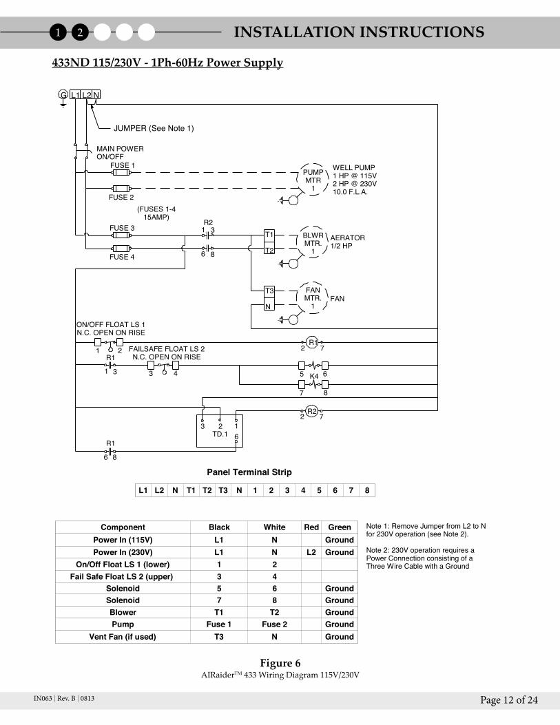
433ND 115/230V-1Ph-60Hz Power Supply
G L1 L2 N
PUMPMTR
1
WELL PUMP1 HP @ 115V2 HP @ 230V10.0 F.L.A.
AIRaider 433ND Wiring Diagram 115/230V
Note 1: Remove Jumper from L2 to Nfor 230V operation (see Note 2).
Note 2: 230V operation requires a Power Connection consisting of aThree Wire Cable with a Ground
JUMPER (See Note 1)
Panel Terminal Strip
ON/OFF FLOAT LS 1N.C. OPEN ON RISE
FAILSAFE FLOAT LS 2N.C. OPEN ON RISE
L1 L2 N T1 T2 T3 N 1 2 3 4 5 6 7 8
Component Black White Red GreenPower In (115V) L1 N GroundPower In (230V) L1 N L2 Ground
On/Off Float LS 1 (lower) 1 2Fail Safe Float LS 2 (upper) 3 4
Solenoid 5 6 GroundSolenoid 7 8 GroundBlower T1 T2 GroundPump Fuse 1 Fuse 2 Ground
Vent Fan (if used) T3 N Ground
Figure 6AIRaiderTM433WiringDiagram115V/230V
433ND 115/230V - 1Ph-60Hz Power Supply
INSTALLATION INSTRUCTIONS1 2

Page 13 of 24IN063 Rev. B 0813
MAIN POWERON/OFF
SUBMPUMP
PUMP FLOATN.O. CLOSE ON RISE
PRESSURE SWITCHPS1
PS2FUSE 1
FUSE 2
FUSE 3
FUSE 4 (FUSES 1-415AMP)
R21 3
6 8
T1
T2
BLWRMTR.
1AERATOR1/2 HP
T3
N
FANMTR.
1FAN
1 2 R12 7
R11 3
3 4K4
5 6
7 8
2 7R2
R1
6 8
3 2 16TD.1
TM
PS3
PS4WN
WNC
AWN
PUSH BUTTON SWITCHTHERMAL SWITCH, NC.
NEON LAMP
BWN
D
1/2 HP 115V 9A
AIRaider 433-S50 ND Wiring Diagram 115V
Panel Terminal Strip
433-S50 ND with 1/2HP Submersible Pump 115V-1Ph-60Hz Power Supply
G L1 L2 N
JUMPER
ON/OFF FLOAT LS 1N.C. OPEN ON RISE
FAILSAFE FLOAT LS 2N.C. OPEN ON RISE
L1 L2 N T1 T2 T3 N 1 2 3 4 5 6 7 8
Component Black White GreenPower In (115V) L1 N Ground
On/Off Float LS 1 (middle) 1 2Fail Safe Float LS 2 (upper) 3 4
Solenoid 5 6 GroundSolenoid 7 8 GroundBlower T1 T2 GroundPump PS-1 WN D Ground
Vent Fan (if used) T3 N GroundPump Float (lower) WN A WN B
Pressure Switch FUSE 1-PS4 WN A-WN D GroundThermal Switch WN B WN C
Neon Lamp WN B WN C
Jumper Lead(3)L2-N
PS1-PS3PS2-PS4
Figure 7AIRaiderTM433-S50WiringDiagram115V
433-S50 ND with ½HP Submersible Pump 115V-1PH-60Hz Power Supply
INSTALLATION INSTRUCTIONS1 2

Page 14 of 24IN063 Rev. B 0813
INSTALLATION INSTRUCTIONS1 2
MAIN POWERON/OFF
SUBMPUMP
PUMP FLOATN.O. CLOSE ON RISE
PS1 PS2
FUSE 1
FUSE 2
FUSE 3
FUSE 4 (FUSES 1-415AMP)
R21 3
6 8
T1
T2
BLWRMTR.
1
AERATOR1/2 HP
T3
N
FANMTR.
1FAN
1 2 R12 7
R11 3 3 4
K45 6
7 8
2 7R2
R1
6 8
3 2 16TD.1
TM
PS3 PS4
WNC
PUSH BUTTON SWITCHTHERMAL SWITCH, NC.
NEON LAMP
BWN
JUMPER
ON/OFF FLOAT LS 1N.C. OPEN ON RISE
FAILSAFE FLOAT LS 2N.C. OPEN ON RISE
PRESSURE SWITCH
1/2 HP 115V 9A
AIRaider 433-S50X Wiring Diagram 115V
433-S50X with 1/2HP Submersible Pump 115V-1Ph-60Hz Power Supply
G L1 L2 N
AWN
Panel Terminal Strip
N
AWN
Cable wired to components outside control box
Connection on terminal strip
Wire Nut
WIRING PROCEDURE:1. Remove Jumpers from panel terminals 4/5 to 7 and N to 8.2. Run 16ga. black wire from Fuse 1 to rear of panel terminal 7.3. Run 16ga. black wire from Fuse 2 to wire nut C.4. Connect components as detailed in table below.
8*R CONNECT BLACK PUMP LEAD TO CONNECTION ON REAR SIDE OF TERMINAL 8
L1 L2 N T1 T2 T3 N 1 2 3 4 5 6 7 8
Component Black White GreenPower In (115V) L1 N Ground
On/Off Float LS 1 (middle) 1 2Fail Safe Float LS 2 (upper) 3 4
Solenoids 5 6 GroundBlower T1 T2 GroundPump 8*R WN A Ground
Vent Fan (if used) T3 N GroundPump Float (lower) WN B WN A
Pressure Switch 7-PS1 PS2-8 GroundThermal Switch WN B WN C
Neon Lamp WN B WN CPush Button Switch WN B WN C
Jumper Lead(3)L2-N
PS1-PS3PS2-PS4
Figure 8AIRaiderTM433-S50XWiringDiagram115V
433-S50X with 1/2HP Submersible Pump 115V-1Ph-60Hz Power Supply
Page 15 of 24IN063 Rev. B 0813
N A1
T1 P1 GND
C
AUX
GN
D
Blow
er
Switc
h Bo
x
Sole
noid
1
Sole
noid
2
G W
B
B W
GB
W
G
OFF
ON
PWR
COM
TRI
G 1
2
3
6 LO
AD
4
5 R
ESIS
TOR
TIM
ER
TIM
ING
RES
ISTO
R3
MEG
OHM
= 5
MIN
Fail S
afe
Floa
t (Up
per)
On/
Off
Floa
t(L
ower
)
Elec
trica
l Enc
losu
re
Y
O
G
Y1Y2
G
AIR
aide
r 321
Wiri
ng D
iagr
am.
11/1
6/10
TR
S
Wire
Col
ors:
Bla
ck
BW
hite
W
Gre
en
GR
ed
R
Wire
Nut
Col
ors:
Gre
en
G
Ora
nge
O
Yello
w
Y
Wire
Nut
G
W
BB
W
G
G R RG R R
Pow
er In
115V
AC50
/60H
Z O
nly
B
BW
R
R R
B W BW
RR
R
W
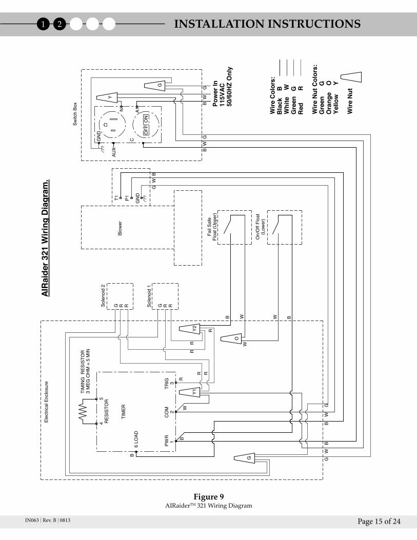
Figure 9AIRaiderTM321WiringDiagram
INSTALLATION INSTRUCTIONS1 2

Page 16 of 24IN063 Rev. B 0813
2.5 Vent Line Installation
Useonly2”,3”or4”Schedule40PVCorequivalentpipeforventline.FollowallapplicableAARST,EPA,and/orStateStandardsforRadonorVOCventing.
1.PlacethelidoftheAIRaiderTMontothetankandclampintoplaceusingtheHexHeadScrewsandWashersprovided.
2.ConnectventlinetoAIRaiderTMlidusingtheenclosedrubbercoupling(SeeFig.10).
3.Theventlinemustberoutedinamannerthatallowsthesystemtoexhaustabovetheleveloftheroof(seeFig.11).Note: When “Freeze Up” is posssible a minimum pipe diameter of 3” is recommended (See Fig. 12).
4.Theventlinemustbepitchedbacktowardthesystemtopreventcondensationbuildup.
5.Cementallfittingsinamannerthatensuresnoleakagewilloccur.Becertaintousecementthatissuitableforpotablewaterapplications. 6.Installweathercapontopoftheventline.Thiscapshouldnotrestrictairflowandmustpreventrain,snowandothercontaminantsfromenteringtheventline.
Failure to install a proper vent line may cause contamination of the water, outgassing of contaminants into the building, and/or limit system performance.
* The Manufacturer has found that vent lines less than 250 equivalent linear feet do not cause a decrease in contaminant removal percentages.90° Bend = 15 Equiv. Linear Ft ; 45° Bend = 7 Equiv. Linear Ft.
Figure 11VentLineInstallation(2inch)
Figure 12VentLineInstallation(3inch)
Figure 10VentLineConnection
INSTALLATION INSTRUCTIONS1 2
Page 17 of 24IN063 Rev. B 0813
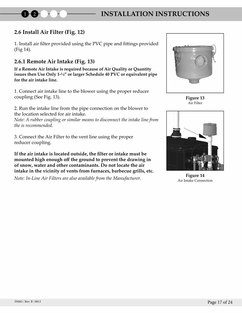
2.6 Install Air Filter (Fig. 12)
1.InstallairfilterprovidedusingthePVCpipeandfittingsprovided(Fig14).
2.6.1 Remote Air Intake (Fig. 13)If a Remote Air Intake is required because of Air Quality or Quantity issues then Use Only 1-¼” or larger Schedule 40 PVC or equivalent pipe for the air intake line.
1.Connectairintakelinetotheblowerusingtheproperreducercoupling(SeeFig.13).
2.Runtheintakelinefromthepipeconnectionontheblowertothelocationselectedforairintake.Note: A rubber coupling or similar means to disconnect the intake line from the is recommended.
3.ConnecttheAirFiltertotheventlineusingtheproperreducercoupling.
If the air intake is located outside, the filter or intake must be mounted high enough off the ground to prevent the drawing in of snow, water and other contaminants. Do not locate the air intake in the vicinity of vents from furnaces, barbecue grills, etc.Note: In-Line Air Filters are also available from the Manufacturer. Figure 14
AirIntakeConnection
Figure 13AirFilter
INSTALLATION INSTRUCTIONS1 2
Page 18 of 24IN063 Rev. B 0813
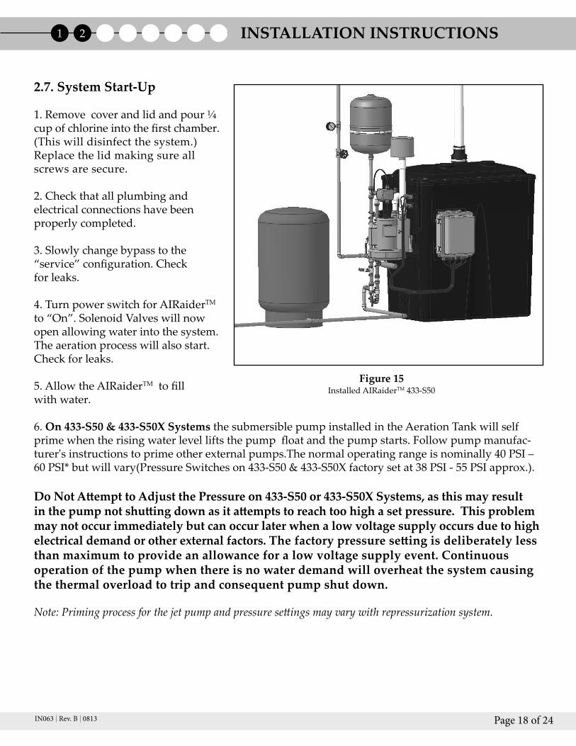
2.7. System Start-Up
1.Removecoverandlidandpour¼cupofchlorineintothefirstchamber.(Thiswilldisinfectthesystem.)Replacethelidmakingsureallscrewsaresecure.
2.Checkthatallplumbingandelectricalconnectionshavebeenproperlycompleted.
3.Slowlychangebypasstothe“service”configuration.Checkforleaks.
4.TurnpowerswitchforAIRaiderTM to“On”.SolenoidValveswillnowopenallowingwaterintothesystem.Theaerationprocesswillalsostart.Checkforleaks.
5.AllowtheAIRaiderTMtofillwithwater.
6.On 433-S50 & 433-S50X SystemsthesubmersiblepumpinstalledintheAerationTankwillselfprimewhentherisingwaterlevelliftsthepumpfloatandthepumpstarts.Followpumpmanufac-turer'sinstructionstoprimeotherexternalpumps.Thenormaloperatingrangeisnominally40PSI–60PSI*butwillvary(PressureSwitcheson433-S50&433-S50Xfactorysetat38PSI-55PSIapprox.).
Do Not Attempt to Adjust the Pressure on 433-S50 or 433-S50X Systems, as this may result in the pump not shutting down as it attempts to reach too high a set pressure. This problem may not occur immediately but can occur later when a low voltage supply occurs due to high electrical demand or other external factors. The factory pressure setting is deliberately less than maximum to provide an allowance for a low voltage supply event. Continuous operation of the pump when there is no water demand will overheat the system causing the thermal overload to trip and consequent pump shut down.
Note: Priming process for the jet pump and pressure settings may vary with repressurization system.
Figure 15InstalledAIRaiderTM433-S50
INSTALLATION INSTRUCTIONS1 2

Page 19 of 24IN063 Rev. B 0813
2.8 System Check
1.Runthesystemthroughacoupleofcyclestoensureallcomponentsareworkingproperly.
2.Theblowertimerispresetfor5minutesdelay.Afterthesolenoidvalvesshut,checkthattheblowercontinuesrunningforthepresetnumberofminutesdelay.
3.Openthetankandcheckthesystem.
a.Removethetanklid.
b.Lowerthewaterlevelinthetankbyopeningabathtubtap,orsimilar,withintheresidence. Thefloatswillfallwiththewaterlevel.Theminimumwaterlevelisreachedwhenthelower floatdrops(excepton433-S50&433-S50Xsystemswhereminimumwaterleveloccurswhen themiddlefloatdrops).Therewillbeanaudibleclickandthesolenoidswillopenallowing thetanktostartfilling;theblowershouldalsostartrunning.Thewaterlevelmustriseregard lessofhowmanytapsareopenwithintheresidence.
c.Whilethetankisfillingliftthelowerfloat(middlefloaton433-S50&433-S50X),waterin flowshouldstopandtheblowerwillremainrunning(untiltheendofthepresetdelay). Releasethelowerfloat.
d.Whilethetankisstillfillinglifttheupperfloat;waterinflowshouldstopandtheblower willremainrunning.Releasetheupperfloat.Pushingdownthelowerfloaton433-S50 and433-S50XSystemswillshutoffthepump.
e.Remembertoshutoffanyopentapswithintheresidence.
4.Replacethelidandsecurewiththefastenersprovided.WiththeSystemrunningcheckthelidforairleaksbetweenlidgasketandtank.Ifleaksoccurthefastenersshouldbetighteneduntilleaksareeliminated.
5.Makesureyouhaveproperlylabeledthesystemwiththenecessaryinstallerinformation(i.e.companyname,phone#,dateinstalled,etc.)andyouhaveleftallsysteminformationwiththehomeowner.
6.TheAIRaiderTMSystemisnowoperational.
INSTALLATION INSTRUCTIONS1 2
Page 20 of 24IN063 Rev. B 0813
3. RetestingAftertheAIRaiderTMinstallation,theinstallershouldperformanotherwateranalysistoensurepropersystemperformance.Thissampleshouldbeperformedoneweekafterthedateofinstallation.
Sampling Procedure:1.Removeaeratorfromfaucetorspigot,ifapplicable.
2.RunwatersothattheAIRaiderTMoperatesfortwocycles.
3.Turnoffwaterfor5minutes.
4.Turnwateronandproceedwithsamplingasperthelaboratoryinstructions.
4. MaintenancePropermaintenanceoftheAIRaiderTMcanpreventpossiblesystemfailureandprovideyearsoftroublefreeservice.
4.1. Six Month Service (recommended)
ThefollowingproceduresshouldbefollowedtomaintaintheAIRaiderTM:•Checkand/orcleantheblowerairintakefilter.•Checkand/orcleananyfiltersorstrainerinstalledontheinletlinetotheAIRaiderTM.Ininstallationswithparticularlyhighlevelsofsediment,cleaningoffiltersmayberequiredmorefrequently.•Checkandcleaninletscreenonpump.•Usingawet/dryvac,cleansedimentfrombottomofaerationtankifnecessary.•Clean(ifnecessary)tankanddiffusersofallmineralbuildup.•Chlorinatetankandlinesbypouring¼cupofchlorineintothefirstaerationchamber.•Checkallcontrolpanelconnectionsandelectricalcomponents(blower,pump,timer,fuses,etc.)forproperoperation.•Checkfloatswitchesforproperoperation.•Inspectventlineforpossibleobstructions.•Runsystemthroughtwocyclestoensuregoodworkingorder.
RETESTING AND MAINTENANCE1 2 3 4

Page 21 of 24IN063 Rev. B 0813
4.2 Annual Service (required)
ThefollowingproceduresshouldbefollowedannuallytomaintaintheAIRaiderTM:
•Cleansolenoidsandswitchcoillocations.
•Checkallhoseconnections.
•Checkand/orcleantheblowerairintakefilter.
•Checkand/orcleananyfiltersorstrainerinstalledontheinletlinetotheAIRaiderTM.
•Checkandcleaninletscreenonpump.
•Usingawet/dryvac,cleansedimentfrombottomofaerationtankifnecessary.
•Clean(ifnecessary)tankanddiffusersofallmineralbuildup.
•Chlorinatetankandlinesbypouring¼cupofchlorineintothefirstaerationchamber.
•Checkallcontrolpanelconnectionsandelectricalcomponents(blower,pump,timer,fuses,etc.)forproperoperation.
•Checkfloatswitchesforproperoperation.
•Inspectventlineforpossibleobstructions.
•Runsystemthroughtwocyclestoensuregoodworkingorder.
•PerformWaterTest.
* Every 3 years during the annual service replace all hoses.** Every 5 years during the annual service replace the solenoid valves.
MAINTENANCE1 2 3 4

Page 22 of 24IN063 Rev. B 0813
Symptom Solution
Nowaterinhouse
Waternotenteringsystem
JetPumpnotfunctioning
Pressureintankislessthan40PSI
Lowwaterflowatfaucets
Blowernotrunning
Blowerdoesnotstoprunning
Loudbangingwhensolenoidsshut
Pumpisshortcycling
Pumpwon'tshutoff
Solenoidschatterwhenclosing
Systemrunningdry
•Checkpower:Switchinonposition,circuitbreakeratpanelinonposition,fusesincontrolpanelintact.
•Checkpressureintank.Ifbelowthepropersettings,resetthepumpasdescribedinSystemStart-up(p.17).•BypassSystem.Ifthereisstillnowater,mainwellpumpmaynotbefunctioning.
•Checkon/offfloatforproperoperation.Replaceifnecessary.
•Checksolenoidsforproperoperation.Replaceifnecessary.•Checkfloatswitchesforproperoperation.Replaceifnecessary.•Checksedimentstrainerand/orfilter(ifapplicable)andcleanifnecessary.
•Checkfuseincontrolpanel.•Checkbreakeratelectricalpanel.•Replacejetpumpifnecessary.
•ResetjetpumpasdescribedinSystemStart-up(p.17).•Checkbladdertank.•Replacejetpumpand/orbladdertankasnecessary.
•Clearsedimentstrainersonfaucets.•Clearpumpinletscreen/waterinjector.•Replacepumpifnecessary.
•Checkfusesincontrolpanel.•Replacetimerifnecessary.•Replaceblowerifnecessary.
•CheckOn/Offfloatforproperoperation.•CheckTimerSettings.•ReplaceTimerRelayifnecessary.
•Installwaterhammersuppressororloopofflexiblehoseinpumpinletline.•Shortenthelengthofpipebetweenthewellpressuretankandthesystem.
•Bladdertankmayberuptured.Replaceifnecessary.•Checkpressureswitchonpumpforproperoperation.
•Callforsupport.
•CheckOn/Offfloatforproperoperation.Replaceifnecessary.
•Checksedimentstrainerand/orfilter(ifapplicable)andcleanifnecessary.•InstallaflowrestrictorormeterdowntheballvalveuntiltheAIRaiderTM outflowis1GPMormorelessthanthewaterflowenteringthesystem.
TROUBLE SHOOTING1 2 3 4 5

Page 23 of 24IN063 Rev. C 0713
LIMITED WARRANTY
Subject to applicable consumer protection legislation, RadonAway warrants that theAIRaider™willbefreefromdefectivematerialsandworkmanshipfortheperiodoftwo(2)yearsfromthedateofpurchase.
Warrantyiscontingentoninstallationinaccordancewiththeinstructionsprovided.Thiswarrantydoesnotapplywhererepairsoralterationshavebeenmadeorattemptedbyothers;or theunithasbeenabusedormisused.Warrantydoesnot includedamageinshipmentunlessthedamageisduetothenegligenceofRadonAway.Tomakeaclaimundertheselimitedwarranties,youmustreturnthedefectiveitemtoRadonAway.Allotherwarranties,expressedorwrittenarenotvalid.RadonAwayisnotresponsibleforinstallationorremovalcostassociatedwiththiswarranty.InnocaseisRadonAwayliablebeyondrepairorreplacementofthedefectiveproductFOBRadonAway.
RADONAWAY SPECIFICALLY DISCLAIMS ANY WARRANTY OF FITNESS FOR A PARTICULAR PURPOSE.
THERE ARE NO WARRANTIES WHICH EXTEND BEYOND THE DESCRIPTION ON THE FACE HEREOF. THERE IS NO WARRANTY OF MERCHANTABILITY. ALL OTHER WARRANTIES, EXPRESSED OR WRITTEN, ARE NOT VALID.
Inordertoobtainserviceunderthiswarranty,theconsumermustcontacttheinstallerordealerwheretheunitwaspurchased.TheinstallerordealermustthencontactRa-donAwaydirectlyforaReturnMerchandiseAuthorization(RMA)numberandship-ping information.No returns can be acceptedwithout an RMA. RadonAwaymayrequirethedefectivepart(s)tobereturnedtoplaceofmanufacture(freightpre-paid)toprocessthewarrantyclaim.Defectivepart(s)coveredunderthiswarrantywillbereplacedorrepairedattheplaceofmanufactureandreturnedtotheinstallerordeal-er(freightpre-paid).Inreplacingorrepairingpartsorproducts,RadonAwayreservestherighttomakesuchchangesinthedetailsofdesignconstruction,arrangementormakematerialsasshallinitsjudgmentconstituteanimprovementoverformerprac-tice.
Recordthefollowingforyourrecords:
SerialNo. DatePurchased:
3 Saber WayP.O. Box 8244Ward Hill, MA 01835
Phone: (800) 767-3703Fax: (978) 521-3964E-mail: [email protected]