Embed Size (px)
Citation preview
INSTALLATION INSTRUCTIONSOILd PheNOLIC SeRIeS
CONTeNTS PAge
1080 DuraLineSeries ...........................................................2-21
1180 DuraLineSeries ..........................................................2-21
2080 DuraLineSeries Maximum Privacy ...........................22-41
2180 DuraLineSeries Maximum Privacy ...........................22-41
In the United States: BOBRICK WAShROOM eQUIPMeNT, INC.200 Commerce Drive, Clifton Park, NY 12065-1350, Telephone: (518) 877-7444 • FAX: 518-877-5029
11611 Hart Street, North Hollywood, CA 91605-5882: (818) 982-9070 • FAX: 818-503-9287or email [email protected]
In Canada: BOBRICK WAShROOM eQUIPMeNT COMPANY45 Rolark Drive, Scarborough, Ontario M1R 3B1 • FAX: (877) 423-8555
Form No. 1080-69 r08/03/12 © 2012 Bobrick Washroom Equipment, Inc. Printed in U.S.A.
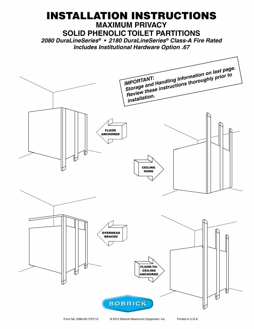
FLOORANCHORED
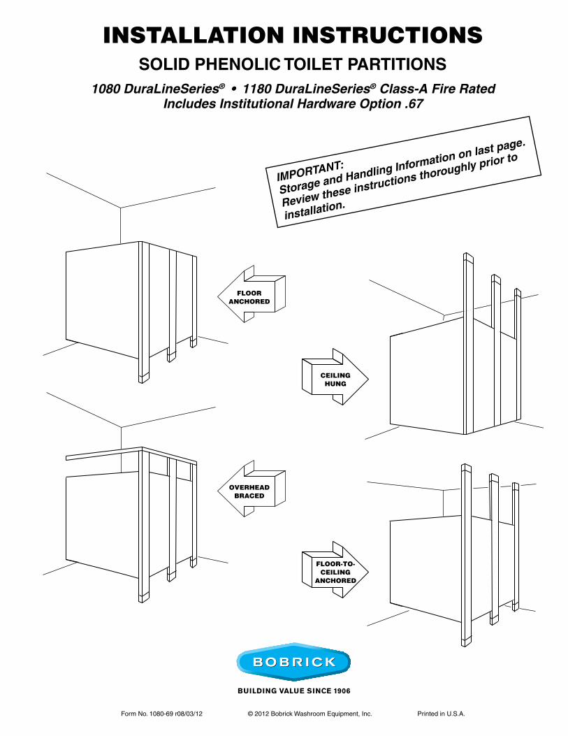
INSTALLATION INSTRUCTIONSsolid phenolic ToileT parTiTions
1080 DuraLineSeries® • 1180 DuraLineSeries® Class-A Fire RatedIncludes Institutional Hardware Option .67
OVERHEADBRACED
CEILINGHUNG
FLOOR-TO- CEILING
ANCHORED
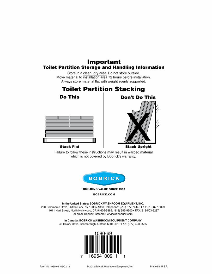
IMPORTANT:
Storage and Handling Information on last page.
Review these instructions thoroughly prior to
installation.
Form No. 1080-69 r08/03/12 © 2012 Bobrick Washroom Equipment, Inc. Printed in U.S.A.
pREpARATION
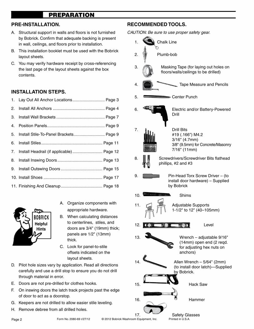
pre-insTallaTion.
A. Structural support in walls and fl oors is not furnished by Bobrick. Confi rm that adequate backing is present in wall, ceilings, and fl oors prior to installation.
B. This installation booklet must be used with the Bobrick layout sheets.
C. You may verify hardware receipt by cross-referencing the last page of the layout sheets against the box contents.
insTallaTion sTeps.
1. Lay Out All Anchor Locations ............................ Page 3
2. Install All Anchors ............................................. Page 4
3. Install Wall Brackets & Wall Posts ..................... Page 7
4. Position Panels .................................................. Page 9
5. Install Stile-To-Panel Brackets ........................... Page 9
6. Install Stiles ..................................................... Page 11
7. Install Headrail (if applicable) .......................... Page 12
8. Install Inswing Doors ....................................... Page 13
9. Install Outswing Doors .................................... Page 15
10. Install Shoes ................................................... Page 17
11. Finishing and Cleanup .................................... Page 18
A. Organize components with
appropriate hardware.
B. When calculating distances to centerlines, stiles, and doors are 3/4" (19mm) thick; panels are 1/2" (13mm) thick.
C. Look for panel-to-stile offsets indicated on the layout sheets.
D. Pilot hole sizes vary by application. Read all directions carefully and use a drill stop to ensure you do not drill through material in error.
E. Doors are not pre-drilled for clothes hooks.
F. On inswing doors the latch track projects past the edge of door to act as a doorstop.
G. Keepers are not drilled to allow easier stile leveling.
H. Remove debris from all drilled holes.
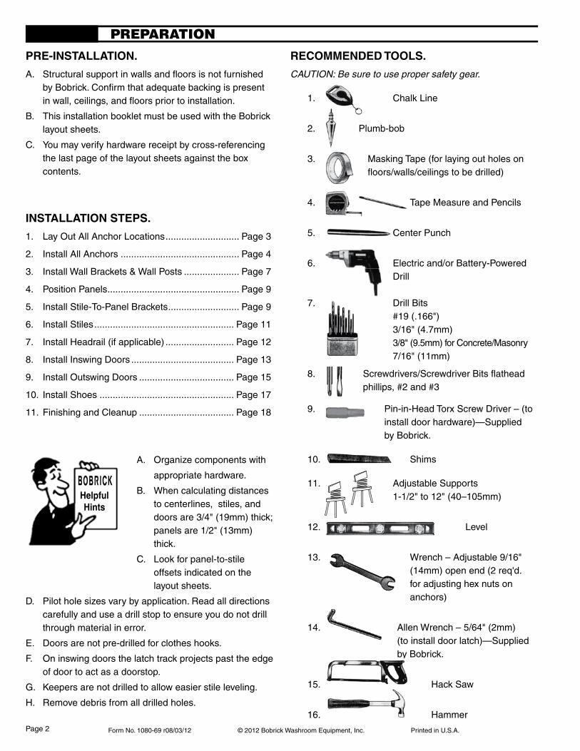
recoMMended Tools.
CAUTION: Be sure to use proper safety gear.
1. Chalk Line
2. Plumb-bob
3. Masking Tape (for laying out holes on fl oors/walls/ceilings to be drilled)
4. Tape Measure and Pencils
5. Center Punch
6. Electric and/or Battery-Powered Drill
7. Drill Bits #19 (.166") 3/16" (4.7mm)
3/8" (9.5mm) for Concrete/Masonry 7/16" (11mm)
8. Screwdrivers/Screwdriver Bits fl athead and phillips, #2 and #3
9. Pin-in-Head Torx Screw Driver – (to install door hardware)—Supplied by Bobrick.
10. Shims
11. Adjustable Supports 1-1/2" to 12" (40–105mm)
12. Level
13. Wrench – Adjustable 9/16" (14mm) open end (2 req'd. for adjusting hex nuts on anchors)
14. Allen Wrench – 5/64" (2mm) (to install door latch)—Supplied by Bobrick.
15. Hack Saw
16. Hammer
6. Electric and/or Battery-Powered Drill
Page 2
Form No. 1080-69 r08/03/12 © 2012 Bobrick Washroom Equipment, Inc. Printed in U.S.A.
LAY OUT ALL ANCHOR LOCATIONS
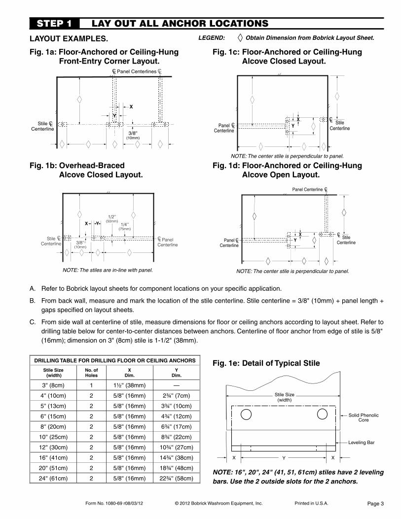
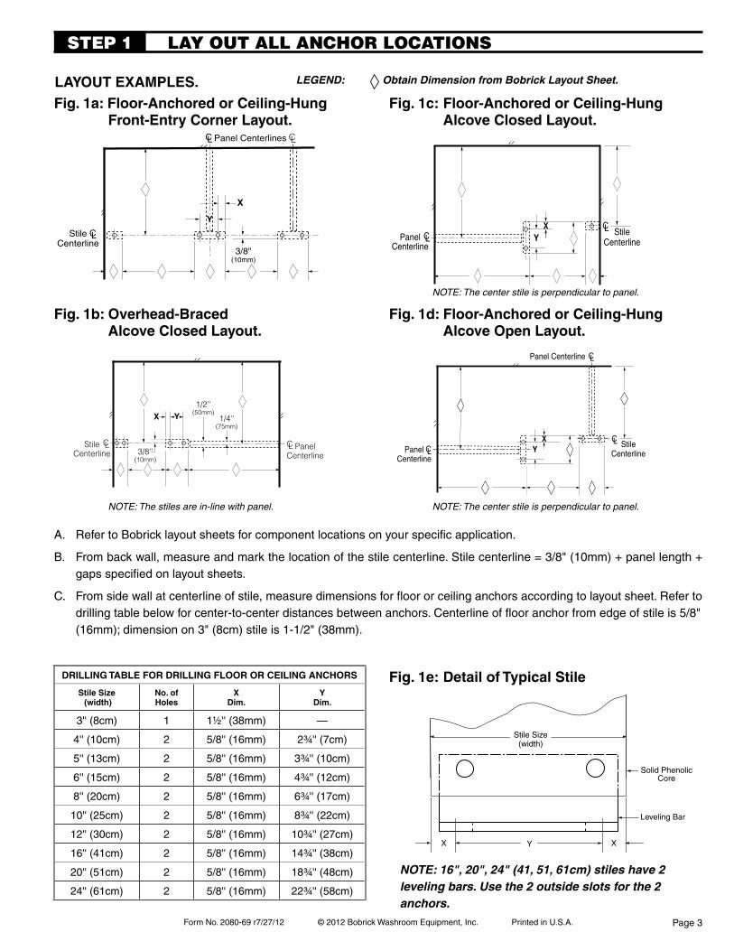
Fig. 1a: Floor-anchored or ceiling-hung Front-entry corner layout.
Fig. 1b: overhead-Braced alcove closed layout.
A. Refer to Bobrick layout sheets for component locations on your specific application.
B. From back wall, measure and mark the location of the stile centerline. Stile centerline = 3/8" (10mm) + panel length + gaps specified on layout sheets.
C. From side wall at centerline of stile, measure dimensions for floor or ceiling anchors according to layout sheet. Refer to drilling table below for center-to-center distances between anchors. Centerline of floor anchor from edge of stile is 5/8" (16mm); dimension on 3" (8cm) stile is 1-1/2" (38mm).
laYoUT eXaMples.
NOTE: The stiles are in-line with panel.
STEp 1LEGEND: Obtain Dimension from Bobrick Layout Sheet.
Fig. 1d: Floor-anchored or ceiling-hung alcove open layout.
Fig. 1c: Floor-anchored or ceiling-hung alcove closed layout.
Fig. 1e: detail of Typical stile
NOTE: 16", 20", 24" (41, 51, 61cm) stiles have 2 leveling bars. Use the 2 outside slots for the 2 anchors.
NOTE: The center stile is perpendicular to panel.
NOTE: The center stile is perpendicular to panel.
CLStileCenterline
PanelCenterline
X Y1/2''
(50mm)1/4''
(75mm)
3/8''(10mm)
CL
CLStileCenterline
X
Y
3/8''(10mm)
CLPanel CenterlinesCL
CLPanelCenterline
XY
CL StileCenterline
CL
XY
CLPanel Centerline
PanelCenterline
CL StileCenterline
Stile Size(width)
Y X
Leveling Bar
Solid PhenolicCore
X
Page 3
drilling TaBle For drilling Floor or ceiling anchors
stile size (width)
no. ofholes
Xdim.
Ydim.
3'' (8cm) 1 1½'' (38mm) —
4'' (10cm) 2 5/8'' (16mm) 2¾'' (7cm)
5'' (13cm) 2 5/8'' (16mm) 3¾'' (10cm)
6'' (15cm) 2 5/8'' (16mm) 4¾'' (12cm)
8'' (20cm) 2 5/8'' (16mm) 6¾'' (17cm)
10'' (25cm) 2 5/8'' (16mm) 8¾'' (22cm)
12'' (30cm) 2 5/8'' (16mm) 10¾'' (27cm)
16'' (41cm) 2 5/8'' (16mm) 14¾'' (38cm)
20'' (51cm) 2 5/8'' (16mm) 18¾'' (48cm)
24'' (61cm) 2 5/8'' (16mm) 22¾'' (58cm)
Form No. 1080-69 r08/03/12 © 2012 Bobrick Washroom Equipment, Inc. Printed in U.S.A.
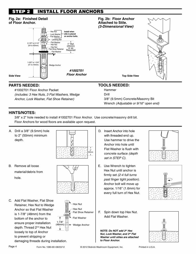
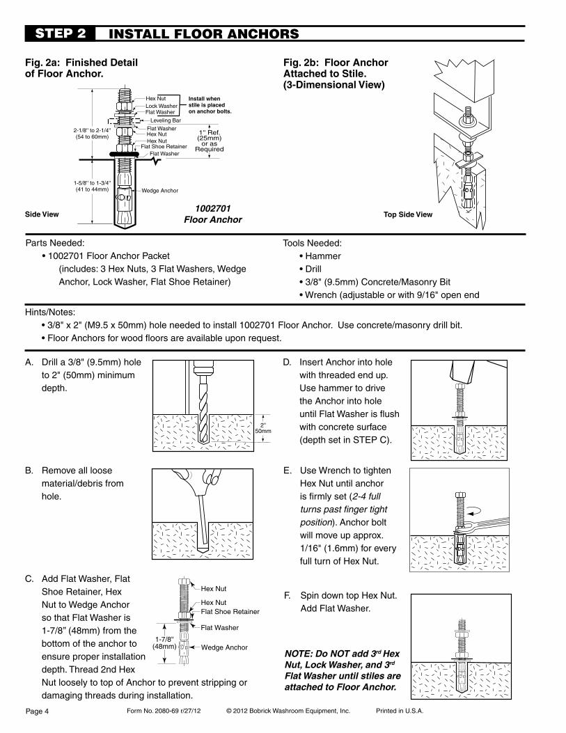
INSTALL FLOOR ANCHORSSTEp 2
NOTE: Do NOT add 3rd Hex Nut, Lock Washer, and 3rd Flat Washer until stiles are attached to Floor Anchor.
hinTs/noTes: 3/8" x 2" hole needed to install #1002701 Floor Anchor. Use concrete/masonry drill bit. Floor Anchors for wood floors are available upon request.
side View Top side View
2''50mm
Hex NutFlat Shoe Retainer
Wedge Anchor1-7/8''
(48mm)
Flat Washer
Hex Nut
parTs needed: #1002701 Floor Anchor Packet (includes: 3 Hex Nuts, 3 Flat Washers, Wedge
Anchor, Lock Washer, Flat Shoe Retainer)
Tools needed: Hammer Drill 3/8" (9.5mm) Concrete/Masonry Bit Wrench (Adjustable or 9/16" open end)
A. Drill a 3/8'' (9.5mm) hole to 2'' (50mm) minimum depth.
B. Remove all loose
material/debris from
hole.
C. Add Flat Washer, Flat Shoe Retainer, Hex Nut to Wedge Anchor so that Flat Washer is 1-7/8'' (48mm) from the bottom of the anchor to ensure proper installation depth. Thread 2nd Hex Nut loosely to top of Anchor to prevent stripping or damaging threads during installation.
E. Use Wrench to tighten Hex Nut until anchor is firmly set (2-4 full turns past finger tight position). Anchor bolt will move up approx. 1/16'' (1.6mm) for every full turn of Hex Nut.
D. Insert Anchor into hole with threaded end up. Use hammer to drive the Anchor into hole until Flat Washer is flush with concrete surface (depth set in STEP C).
F. Spin down top Hex Nut. Add Flat Washer.
Fig. 2a: Finished detail of Floor anchor.
#1002701Floor Anchor
Fig. 2b: Floor anchor attached to stile. (3-Dimensional View)
Flat Washer
Hex NutHex Nut
Flat Shoe Retainer
Wedge Anchor
2-1/8'' to 2-1/4''(54 to 60mm)
1-5/8'' to 1-3/4''(41 to 44mm)
Flat Washer
Leveling Bar
Install whenstile is placedon anchor bolts.
Flat Washer
Hex NutLock Washer
1'' Ref.(25mm)
or asRequired
Page 4
Form No. 1080-69 r08/03/12 © 2012 Bobrick Washroom Equipment, Inc. Printed in U.S.A.
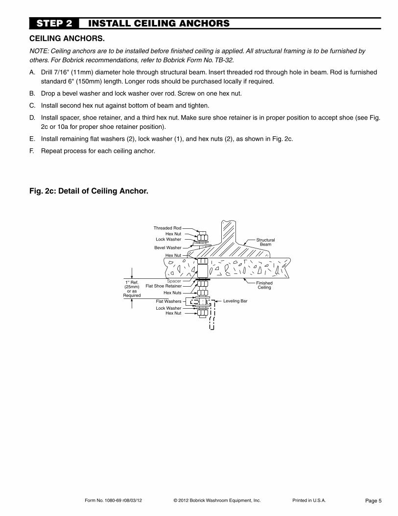
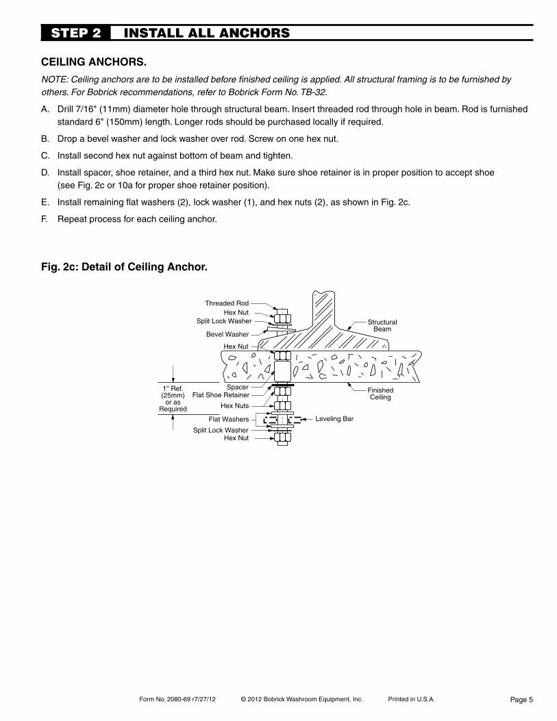
INSTALL CEILING ANCHORS
ceiling anchors.
NOTE: Ceiling anchors are to be installed before finished ceiling is applied. All structural framing is to be furnished by others. For Bobrick recommendations, refer to Bobrick Form No. TB-32.
A. Drill 7/16" (11mm) diameter hole through structural beam. Insert threaded rod through hole in beam. Rod is furnished standard 6" (150mm) length. Longer rods should be purchased locally if required.
B. Drop a bevel washer and lock washer over rod. Screw on one hex nut.
C. Install second hex nut against bottom of beam and tighten.
D. Install spacer, shoe retainer, and a third hex nut. Make sure shoe retainer is in proper position to accept shoe (see Fig. 2c or 10a for proper shoe retainer position).
E. Install remaining flat washers (2), lock washer (1), and hex nuts (2), as shown in Fig. 2c.
F. Repeat process for each ceiling anchor.
STEp 2
Fig. 2c: detail of ceiling anchor.
FinishedCeiling
Hex NutLock Washer
Bevel Washer
Hex Nut
StructuralBeam
SpacerFlat Shoe Retainer
Hex Nuts
Flat Washers
Lock Washer
Leveling Bar
Threaded Rod
Hex Nut
1'' Ref.(25mm)
or asRequired
Page 5
Form No. 1080-69 r08/03/12 © 2012 Bobrick Washroom Equipment, Inc. Printed in U.S.A.
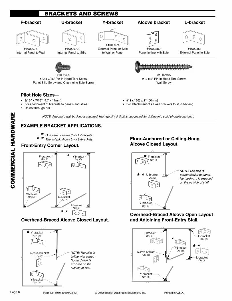
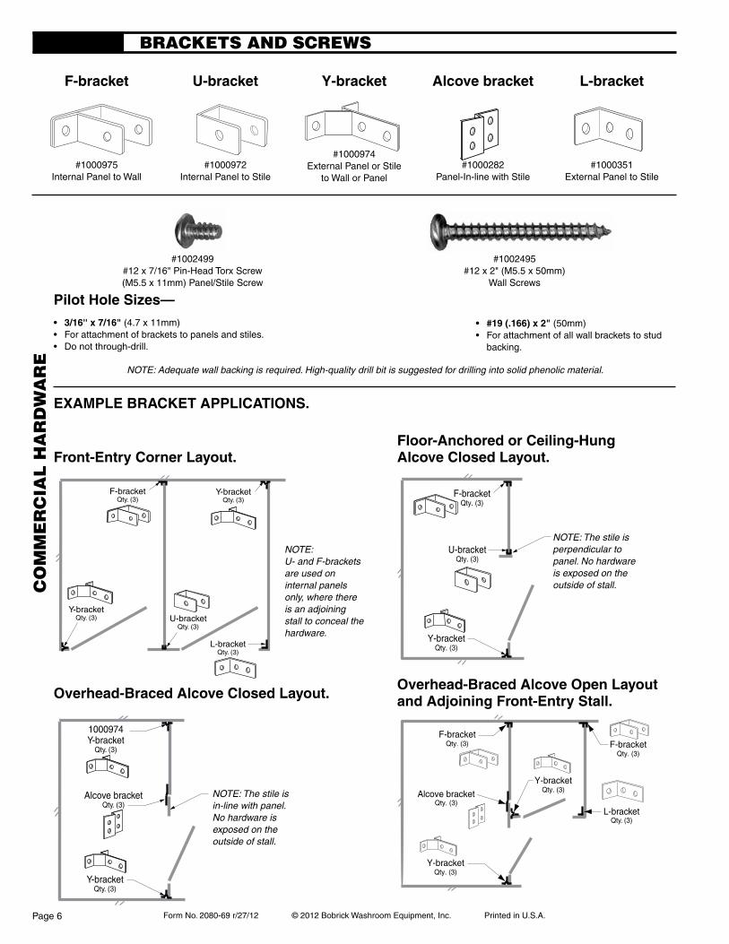
BRACkETS AND SCREwS
#1000975Internal Panel to Wall
F-bracket
#1000972Internal Panel to Stile
U-bracket
#1000974External Panel or Stile
to Wall or Panel
Y-bracket
#1000351External Panel to Stile
l-bracket
overhead-Braced alcove open layout and adjoining Front-entry stall.overhead-Braced alcove closed layout.
Front-entry corner layout.
NOTE: Adequate wall backing is required. High-quality drill bit is suggested for drilling into solid phenolic material.
eXaMple BrackeT applicaTions.
• 3/16"x7/16"(4.7 x 11mm)• Forattachmentofbracketstopanelsandstiles.• Donotthrough-drill.
• #19(.166)x2"(50mm)• Forattachmentofallwallbracketstostudbacking.
pilot hole sizes—
NOTE: The stile is perpendicular to panel. No hardware is exposed on the outside of stall.
Floor-anchored or ceiling-hungalcove closed layout.
NOTE: The stile is in-line with panel.No hardware is exposed on the outside of stall.
#1000282Panel-In-line with Stile
alcove bracket
One asterik shows Y- or F-brackets Two asterik shows L- or U-brackets* * *
*
* *
* *
* *
* *
*
#1002495#12 x 2" Pin-in-Head Torx Screw
Wall Screw
#1002499#12 x 7/16" Pin-in-Head Torx Screw
Panel/Stile Screw and Channel to Stile Screw
F-bracketQty. (3)
Y-bracketQty. (3) U-bracket
Qty. (3)
L-bracketQty. (3)
Y-bracketQty. (3)
Y-bracketQty. (3)
Y-bracketQty. (3)
Alcove bracketQty. (3)
Y-bracketQty. (3)
F-bracketQty. (3)
Alcove bracketQty. (3)
F-bracketQty. (3)
Y-bracketQty. (3)
L-bracketQty. (3)
Y-bracketQty. (3)
F-bracketQty. (3)
U-bracketQty. (3)
CO
mm
ER
CIA
L H
AR
Dw
AR
E
Page 6
Form No. 1080-69 r08/03/12 © 2012 Bobrick Washroom Equipment, Inc. Printed in U.S.A.
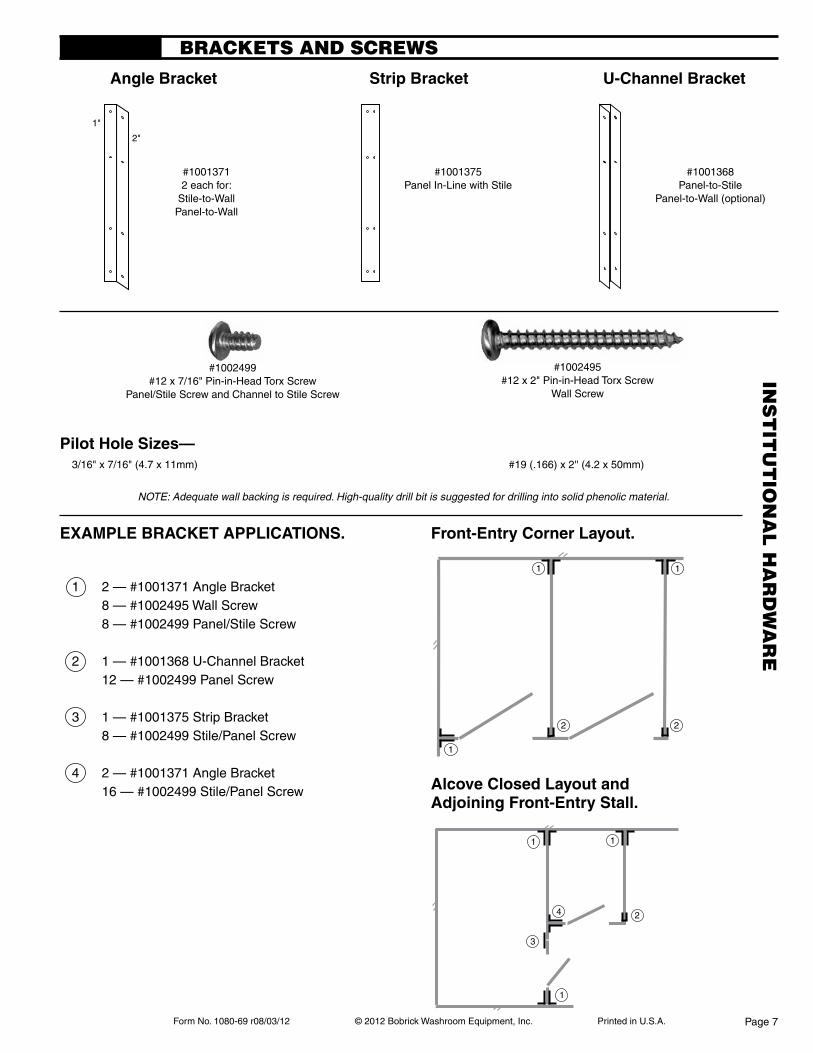
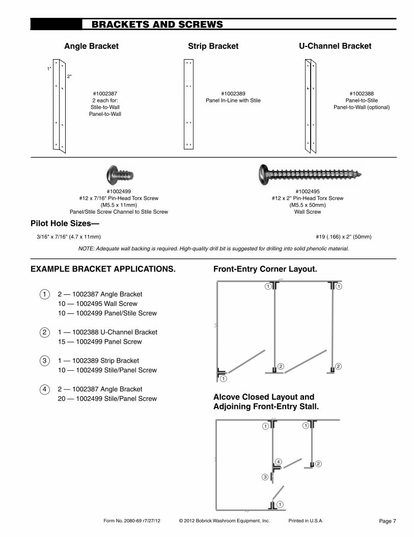
BRACkETS AND SCREwS
1 2 — #1001371 Angle Bracket 8 — #1002495 Wall Screw 8 — #1002499 Panel/Stile Screw
2 1 — #1001368 U-Channel Bracket 12 — #1002499 Panel Screw
3 1 — #1001375 Strip Bracket 8 — #1002499 Stile/Panel Screw
4 2 — #1001371 Angle Bracket 16 — #1002499 Stile/Panel Screw
#10013712 each for:
Stile-to-WallPanel-to-Wall
angle Bracket
#1001375Panel In-Line with Stile
strip Bracket
#1001368Panel-to-Stile
Panel-to-Wall (optional)
U-channel Bracket
alcove closed layout and adjoining Front-entry stall.
Front-entry corner layout.eXaMple BrackeT applicaTions.
#1002495#12 x 2" Pin-in-Head Torx Screw
Wall Screw
#1002499#12 x 7/16" Pin-in-Head Torx Screw
Panel/Stile Screw and Channel to Stile Screw
pilot hole sizes— 3/16" x 7/16" (4.7 x 11mm) #19 (.166) x 2'' (4.2 x 50mm)
NOTE: Adequate wall backing is required. High-quality drill bit is suggested for drilling into solid phenolic material.
2"
1"
2"
1"
2"
1"
1
22
1 1
1
3
4 2
11
INS
TIT
UT
ION
AL
HA
RD
wA
RE
Page 7
Form No. 1080-69 r08/03/12 © 2012 Bobrick Washroom Equipment, Inc. Printed in U.S.A.
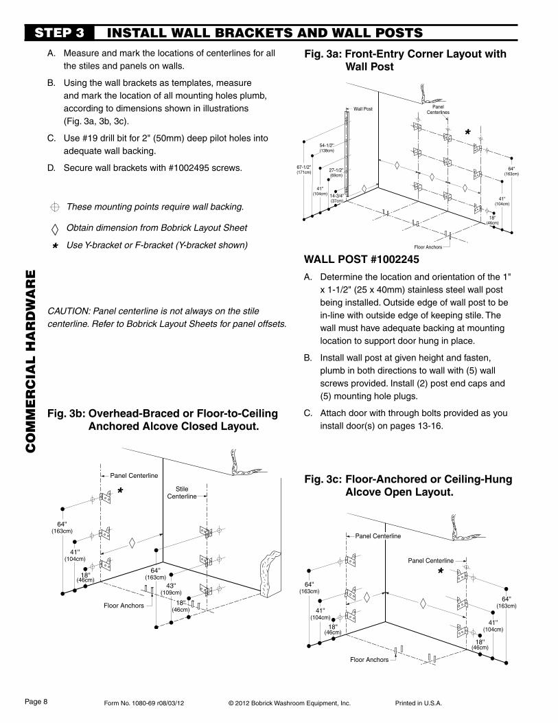
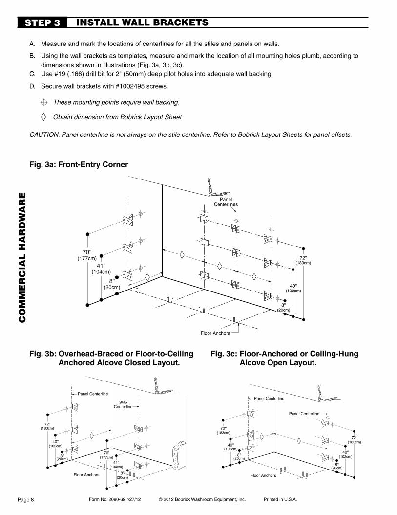
A. Measure and mark the locations of centerlines for all the stiles and panels on walls.
B. Using the wall brackets as templates, measure and mark the location of all mounting holes plumb, according to dimensions shown in illustrations
(Fig. 3a, 3b, 3c).
C. Use #19 drill bit for 2" (50mm) deep pilot holes into adequate wall backing.
D. Secure wall brackets with #1002495 screws.
These mounting points require wall backing.
Obtain dimension from Bobrick Layout Sheet
Use Y-bracket or F-bracket (Y-bracket shown)
INSTALL wALL BRACkETS AND wALL pOSTSSTEp 3
Fig.3a:Front-EntryCornerLayoutwith Wall post
Fig.3b:Overhead-BracedorFloor-to-Ceiling anchored alcove closed layout.
Fig.3c:Floor-AnchoredorCeiling-Hung alcove open layout.
CAUTION: Panel centerline is not always on the stile centerline. Refer to Bobrick Layout Sheets for panel offsets.
67-1/2''(171cm)
41''(104cm)
64''(163cm)
PanelCenterlines
Floor Anchors
14-3/4''(37cm)
18''(46cm)
Wall Post
54-1/2''(138cm)
27-1/2''(69cm)
41''(104cm)
64''(163cm)
18''(46cm)
Panel Centerline
64''(163cm)
43''(109cm)
Floor Anchors 18''(46cm)
StileCenterline
41''(104cm)
64''(163cm)
18''(46cm)
Panel Centerline
64''(163cm)
Floor Anchors
Panel Centerline
18''(46cm)
41''(104cm)
41''(104cm)
WALLPOST#1002245
A. Determine the location and orientation of the 1" x 1-1/2" (25 x 40mm) stainless steel wall post being installed. Outside edge of wall post to be in-line with outside edge of keeping stile. The wall must have adequate backing at mounting location to support door hung in place.
B. Install wall post at given height and fasten, plumb in both directions to wall with (5) wall screws provided. Install (2) post end caps and (5) mounting hole plugs.
C. Attach door with through bolts provided as you install door(s) on pages 13-16.
*
*
*
*
CO
mm
ER
CIA
L H
AR
Dw
AR
E
Page 8
Form No. 1080-69 r08/03/12 © 2012 Bobrick Washroom Equipment, Inc. Printed in U.S.A.
PanelCenterlines
Floor Anchors
18-1/4''(46cm)
18-1/4''(46cm)
18-1/4''(46cm)
3/4''(19mm)
12-1/8''(31cm)
To bottom of angle
68''(172cm)
41''(104cm) 14''
(35cm)
Wall Post
56-1/2''(142cm)
27-1/2''(69cm)
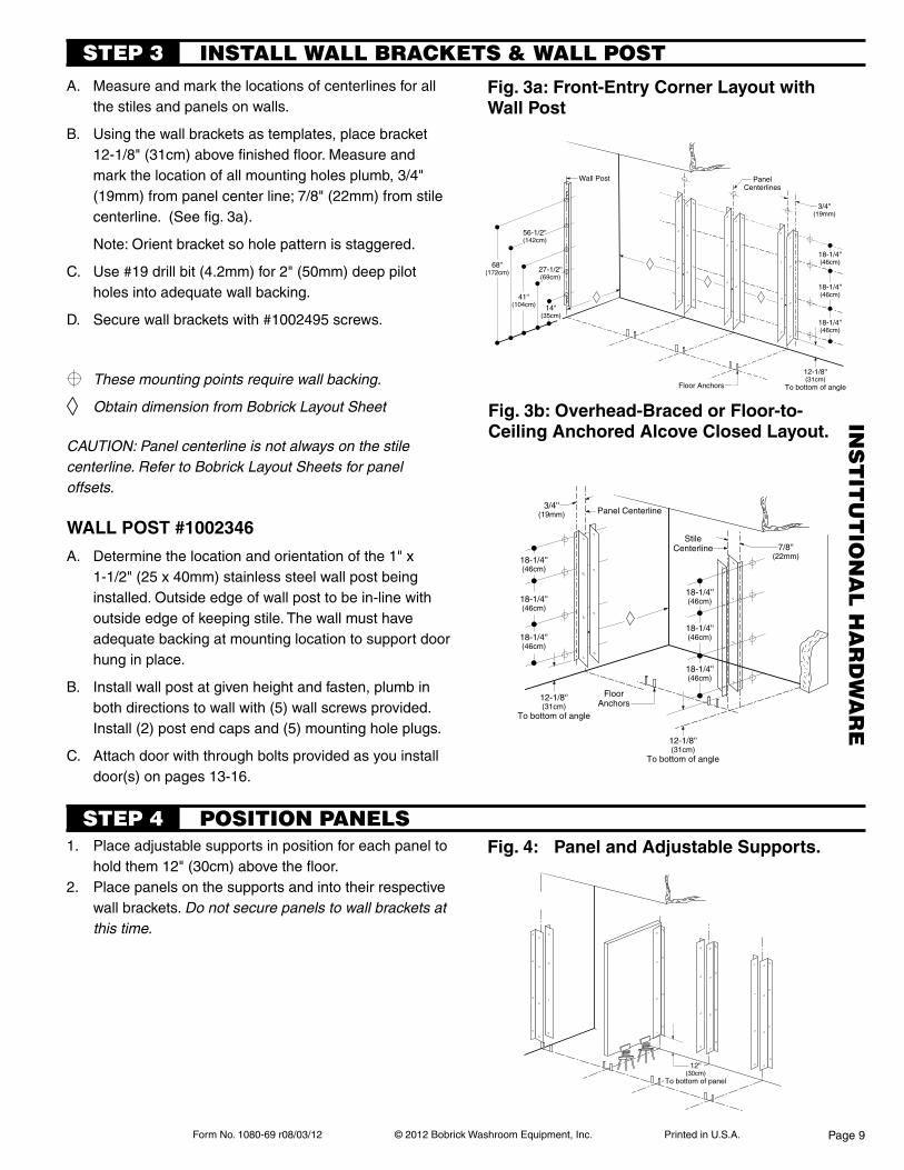
A. Measure and mark the locations of centerlines for all the stiles and panels on walls.
B. Using the wall brackets as templates, place bracket 12-1/8" (31cm) above finished floor. Measure and mark the location of all mounting holes plumb, 3/4" (19mm) from panel center line; 7/8" (22mm) from stile centerline. (See fig. 3a).
Note: Orient bracket so hole pattern is staggered.
C. Use #19 drill bit (4.2mm) for 2" (50mm) deep pilot holes into adequate wall backing.
D. Secure wall brackets with #1002495 screws.
INSTALL wALL BRACkETS & wALL pOSTSTEp 3
Fig.3a:Front-EntryCornerLayoutwithWall post
1. Place adjustable supports in position for each panel to hold them 12" (30cm) above the floor.
2. Place panels on the supports and into their respective wall brackets. Do not secure panels to wall brackets at this time.
Fig.4: PanelandAdjustableSupports.
STEp 4 pOSITION pANELS
18-1/4''(46cm)
Panel Centerline
18-1/4''(46cm)
FloorAnchors
StileCenterline
18-1/4''(46cm)
18-1/4''(46cm)
18-1/4''(46cm)
12-1/8''(31cm)
To bottom of angle
7/8''(22mm)
3/4''(19mm)
12-1/8''(31cm)
To bottom of angle
18-1/4''(46cm)
12''(30cm)
To bottom of panel
WALLPOST#1002346
A. Determine the location and orientation of the 1" x 1-1/2" (25 x 40mm) stainless steel wall post being installed. Outside edge of wall post to be in-line with outside edge of keeping stile. The wall must have adequate backing at mounting location to support door hung in place.
B. Install wall post at given height and fasten, plumb in both directions to wall with (5) wall screws provided. Install (2) post end caps and (5) mounting hole plugs.
C. Attach door with through bolts provided as you install door(s) on pages 13-16.
CAUTION: Panel centerline is not always on the stile centerline. Refer to Bobrick Layout Sheets for panel offsets.
Fig.3b:Overhead-BracedorFloor-to-ceiling anchored alcove closed layout.
These mounting points require wall backing.
Obtain dimension from Bobrick Layout Sheet INS
TIT
UT
ION
AL
HA
RD
wA
RE
Page 9
Form No. 1080-69 r08/03/12 © 2012 Bobrick Washroom Equipment, Inc. Printed in U.S.A.
64''(163cm)
43''(109cm)
18''(46cm)
64''(163cm)
18''(46cm)
12''(31cm)
41''(104cm)
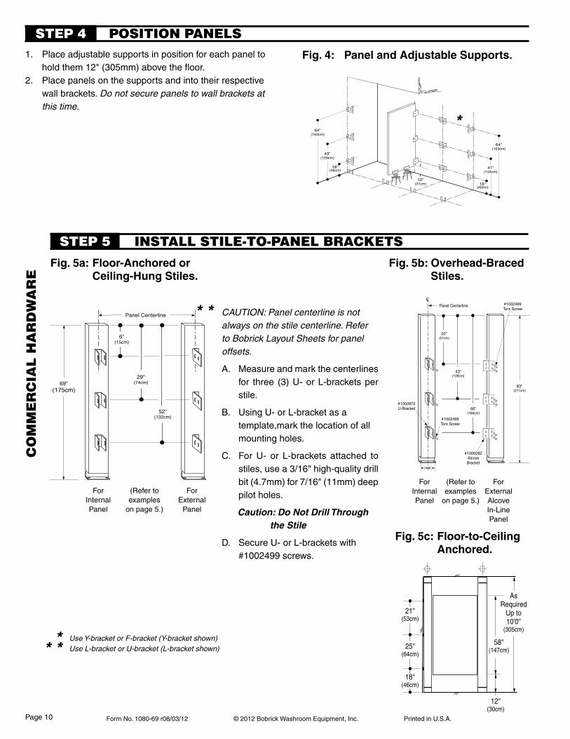
1. Place adjustable supports in position for each panel to hold them 12" (305mm) above the floor.
2. Place panels on the supports and into their respective wall brackets. Do not secure panels to wall brackets at this time.
Fig.4: PanelandAdjustableSupports.
Fig.5a:Floor-Anchoredor ceiling-hung stiles.
Fig.5b:Overhead-Braced stiles.
CAUTION: Panel centerline is not always on the stile centerline. Refer to Bobrick Layout Sheets for panel offsets.
A. Measure and mark the centerlines for three (3) U- or L-brackets per stile.
B. Using U- or L-bracket as a template,mark the location of all mounting holes.
C. For U- or L-brackets attached to stiles, use a 3/16" high-quality drill bit (4.7mm) for 7/16" (11mm) deep pilot holes.
Caution: Do Not Drill Through the Stile
D. Secure U- or L-brackets with #1002499 screws.
ForInternalPanel
ForExternal
Panel
STEp 4 pOSITION pANELS
INSTALL STILE-TO-pANEL BRACkETSSTEp 5
ForInternalPanel
ForExternalAlcoveIn-LinePanel
(Refer to examples
on page 5.)
(Refer to examples
on page 5.)
Fig.5c:Floor-to-Ceiling anchored.
83''(211cm)
20''(51cm)
66''(168cm)
43''(109cm)
#1000972U-Bracket
Panel Centerline
#1000282AlcoveBracket
#1002499Torx Screw
#1002499Torx Screw
CL
Panel Centerline
6''(15cm)
69''(175cm)
29''(74cm)
52''(132cm)
21''(53cm)
25''(64cm)
18''(46cm)
58''(147cm)
AsRequired
Up to10'0''
(305cm)
12''(30cm)
Use Y-bracket or F-bracket (Y-bracket shown) Use L-bracket or U-bracket (L-bracket shown)
*
* *
* * *
CO
mm
ER
CIA
L H
AR
Dw
AR
E
Page 10
Form No. 1080-69 r08/03/12 © 2012 Bobrick Washroom Equipment, Inc. Printed in U.S.A.
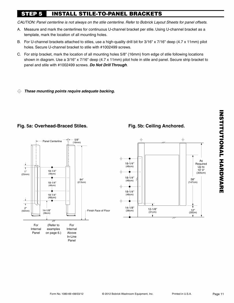
Fig.5a:Overhead-BracedStiles.
CAUTION: Panel centerline is not always on the stile centerline. Refer to Bobrick Layout Sheets for panel offsets.
A. Measure and mark the centerlines for continuous U-channel bracket per stile. Using U-channel bracket as a template, mark the location of all mounting holes.
B. For U-channel brackets attached to stiles, use a high-quality drill bit for 3/16" x 7/16" deep (4.7 x 11mm) pilot holes. Secure U-channel bracket to stile with #1002499 screws.
C. For strip bracket, mark the location of all mounting holes 5/8" (16mm) from edge of stile following locations shown in diagram. Use a 3/16" x 7/16" deep (4.7 x 11mm) pilot hole in stile and panel. Secure strip bracket to panel and stile with #1002499 screws. Do Not Drill Through.
INSTALL STILE-TO-pANEL BRACkETSSTEp 5
ForInternalPanel
ForInternalAlcoveIn-LinePanel
(Refer to examples
on page 6.)
Fig.5b:CeilingAnchored.
Panel Centerline
84''(213cm)
18-1/4''(46cm)
18-1/4''(46cm)
18-1/4''(46cm)
Finish Face of Floor
5/8''(16mm)
1''(25mm)
2''(50mm) 14-1/8''
(36cm)
58''(147cm)
AsRequired
Up to10' 0''
(305cm)
12''(30cm)
12-1/8''(31cm)
18-1/4''(46cm)
18-1/4''(46cm)
18-1/4''(46cm)
14-1/8''(36cm)
These mounting points require adequate backing.
INS
TIT
UT
ION
AL
HA
RD
wA
RE
Page 11
Form No. 1080-69 r08/03/12 © 2012 Bobrick Washroom Equipment, Inc. Printed in U.S.A.
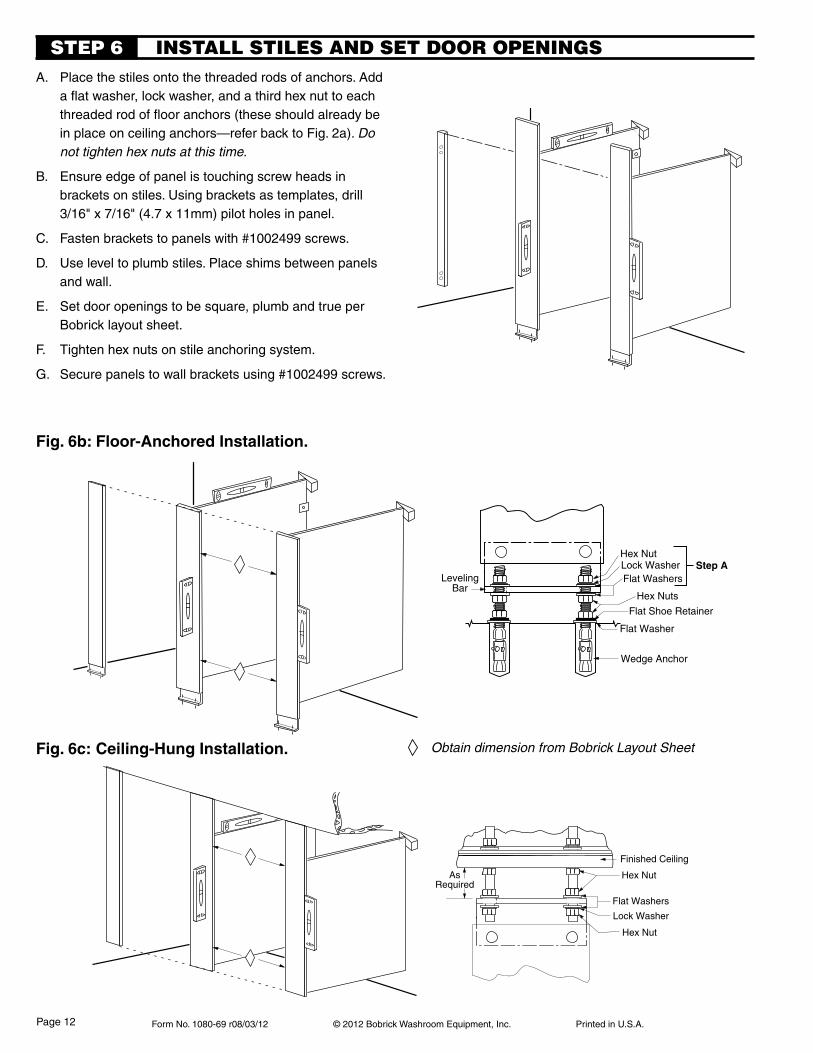
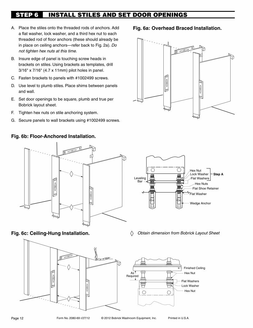
A. Place the stiles onto the threaded rods of anchors. Add a flat washer, lock washer, and a third hex nut to each threaded rod of floor anchors (these should already be in place on ceiling anchors—refer back to Fig. 2a). Do not tighten hex nuts at this time.
B. Ensure edge of panel is touching screw heads in brackets on stiles. Using brackets as templates, drill
3/16" x 7/16" (4.7 x 11mm) pilot holes in panel.
C. Fasten brackets to panels with #1002499 screws.
D. Use level to plumb stiles. Place shims between panels and wall.
E. Set door openings to be square, plumb and true per Bobrick layout sheet.
F. Tighten hex nuts on stile anchoring system.
G. Secure panels to wall brackets using #1002499 screws.
Fig.6b:Floor-AnchoredInstallation.
Fig.6c:Ceiling-HungInstallation.
INSTALL STILES AND SET DOOR OpENINGSSTEp 6
Hex Nut
Flat WashersLock Washer
Hex Nuts
Flat Shoe Retainer
Wedge Anchor
LevelingBar
Step A
Flat Washer
AsRequired
Hex Nut
Lock Washer
Flat Washers
Hex Nut
Finished Ceiling
Obtain dimension from Bobrick Layout Sheet
Page 12
Form No. 1080-69 r08/03/12 © 2012 Bobrick Washroom Equipment, Inc. Printed in U.S.A.
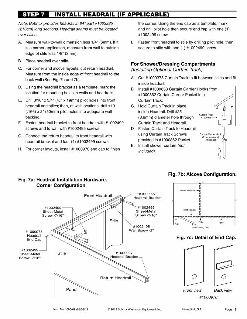
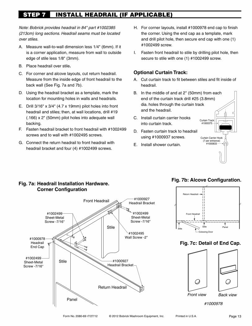
Note: Bobrick provides headrail in 84" part #1002385 (213cm) long sections. Headrail seams must be located over stiles.
A. Measure wall-to-wall dimension less 1/4" (6mm). If it is a corner application, measure from wall to outside edge of stile less 1/8" (3mm).
B. Place headrail over stile.
C. For corner and alcove layouts, cut return headrail. Measure from the inside edge of front headrail to the back wall (See Fig. 7a and 7b).
D. Using the headrail bracket as a template, mark the location for mounting holes in walls and headrails.
E. Drill 3/16" x 3/4" (4.7 x 19mm) pilot holes into front headrail and stiles; then, at wall locations, drill #19 (.166) x 2" (50mm) pilot holes into adequate wall backing.
F. Fasten headrail bracket to front headrail with #1002499 screws and to wall with #1002495 screws.
G. Connect the return headrail to front headrail with headrail bracket and four (4) #1002499 screws.
H. For corner layouts, install #1000978 end cap to finish
the corner. Using the end cap as a template, mark and drill pilot hole then secure end cap with one (1) #1002499 screw.
I. Fasten front headrail to stile by drilling pilot hole, then secure to stile with one (1) #1002499 screw.
Fig.7b:AlcoveConfiguration.
INSTALL HEADRAIL (IF AppLICABLE) STEp 7
Stile
Stile
Panel
Return Headrail
#1002495Wall Screw -2''
Front Headrail
#1002499Sheet-MetalScrew -7/16''
#1000927Headrail Bracket
#1000978HeadrailEnd Cap
#1002499Sheet-MetalScrew -7/16''
#1002499Sheet-MetalScrew -7/16''
#1000927Headrail Bracket
For shower/dressing compartments(Installing Optional Curtain Track)
#1000978
Back viewFront view
Fig.7c:DetailofEndCap.
StileStile Panel
Front Headrail
Outswing Door
Return Headrail
Fig.7a:HeadrailInstallationHardware. CornerConfiguration
Curtain Carrier Hook(7 per entrance)
#1000833
Curtain Track#1000375
A. Cut #1000375 Curtain Track to fit between stiles and fit inside headrail.
B. Install #1000833 Curtain Carrier Hooks from #1000862 Curtain Carrier Packet into Curtain Track.
C. Hold Curtain Track in place inside Headrail. Drill #25 (3.8mm) diameter hole through Curtain Track and Headrail.
D. Fasten Curtain Track to Headrail using Curtain Track Screws provided in #1000862 Packet
E. Install shower curtain (not included).
Page 13
Form No. 1080-69 r08/03/12 © 2012 Bobrick Washroom Equipment, Inc. Printed in U.S.A.
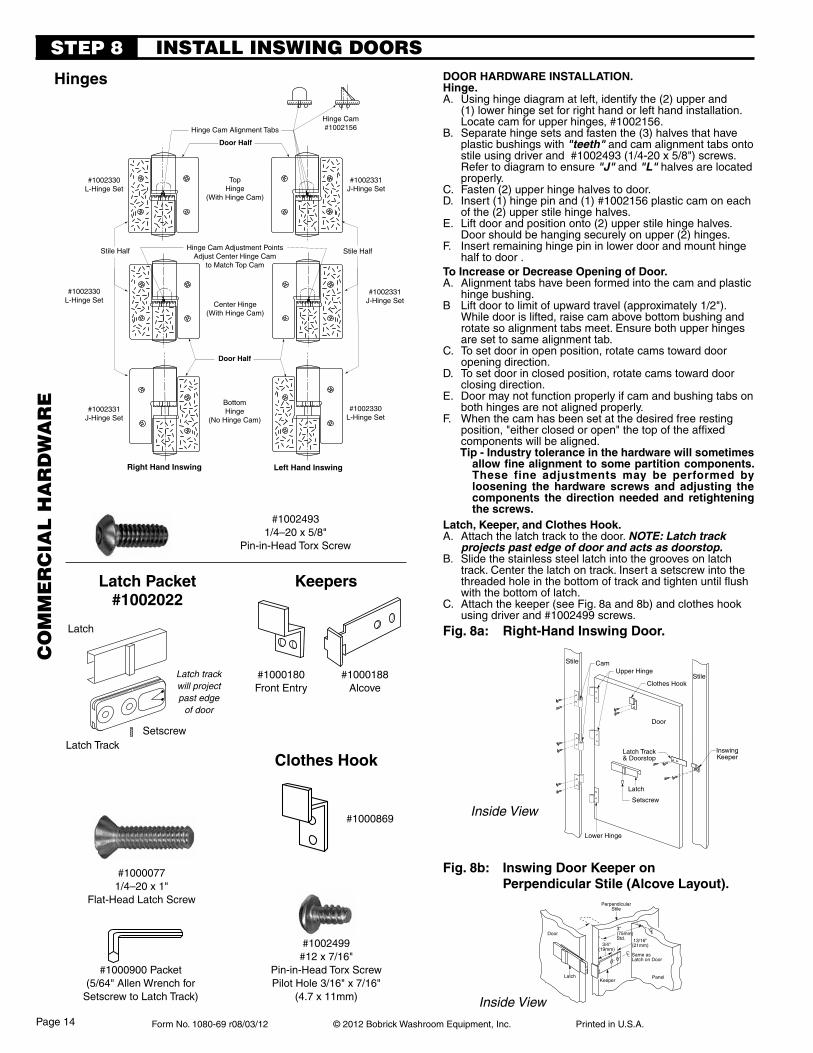
Clothes Hook
Upper Hinge
Lower Hinge
Setscrew
Latch
Latch Track& Doorstop
InswingKeeper
Stile
Stile
Door
Cam
#1000188Alcove
latch packet #1002022
keepers
clothes hook
Latch
Door
PerpendicularStile
Panel
3''(75mm)Std.
3/4''(19mm)
13/16''(21mm)
CL Same asLatch on Door
CL
Keeper
Fig. 8b: inswing door keeper on perpendicular stile (alcove layout).
#1000180Front Entry
#1000869
Latch TrackSetscrew
#1000900 Packet(5/64" Allen Wrench for
Setscrew to Latch Track)
Latch track will projectpast edge
of door
INSTALL INSwING DOORSSTEp 8
Latch
Inside View
hinges
#10024931/4–20 x 5/8"
Pin-in-Head Torx Screw
#10000771/4–20 x 1"
Flat-Head Latch Screw
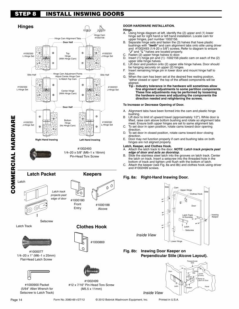
door hardWare insTallaTion.hinge.A. Using hinge diagram at left, identify the (2) upper and
(1) lower hinge set for right hand or left hand installation. Locate cam for upper hinges, #1002156.
B. Separate hinge sets and fasten the (3) halves that have plastic bushings with "teeth" and cam alignment tabs onto stile using driver and #1002493 (1/4-20 x 5/8") screws. Refer to diagram to ensure "J" and "L" halves are located properly.
C. Fasten (2) upper hinge halves to door.D. Insert (1) hinge pin and (1) #1002156 plastic cam on each
of the (2) upper stile hinge halves.E. Lift door and position onto (2) upper stile hinge halves.
Door should be hanging securely on upper (2) hinges.F. Insert remaining hinge pin in lower door and mount hinge
half to door .To increase or decrease opening of door.A. Alignment tabs have been formed into the cam and plastic
hinge bushing.B Lift door to limit of upward travel (approximately 1/2").
While door is lifted, raise cam above bottom bushing and rotate so alignment tabs meet. Ensure both upper hinges are set to same alignment tab.
C. To set door in open position, rotate cams toward door opening direction.
D. To set door in closed position, rotate cams toward door closing direction.
E. Door may not function properly if cam and bushing tabs on both hinges are not aligned properly.
F. When the cam has been set at the desired free resting position, "either closed or open" the top of the affixed components will be aligned. Tip - industry tolerance in the hardware will sometimes
allowfinealignmenttosomepartitioncomponents.These fine adjustments may be performed by loosening the hardware screws and adjusting the components the direction needed and retightening the screws.
latch, keeper, and clothes hook.A. Attach the latch track to the door. NOTE: Latch track
projects past edge of door and acts as doorstop.B. Slide the stainless steel latch into the grooves on latch
track. Center the latch on track. Insert a setscrew into the threaded hole in the bottom of track and tighten until flush with the bottom of latch.
C. Attach the keeper (see Fig. 8a and 8b) and clothes hook using driver and #1002499 screws.
Fig. 8a: right-hand inswing door.
Inside View
#1002499#12 x 7/16"
Pin-in-Head Torx ScrewPilot Hole 3/16" x 7/16"
(4.7 x 11mm)
Door Half
Center Hinge(With Hinge Cam)
#1002331J-Hinge Set
#1002330L-Hinge Set
#1002331J-Hinge Set
Left Hand Inswing
#1002330L-Hinge Set
Door Half
TopHinge
(With Hinge Cam)
Hinge Cam#1002156Hinge Cam Alignment Tabs
Stile HalfStile Half
Right Hand Inswing
#1002331J-Hinge Set
#1002330L-Hinge Set
Hinge Cam Adjustment PointsAdjust Center Hinge Cam
to Match Top Cam
BottomHinge
(No Hinge Cam)
CO
mm
ER
CIA
L H
AR
Dw
AR
E
Page 14
Form No. 1080-69 r08/03/12 © 2012 Bobrick Washroom Equipment, Inc. Printed in U.S.A.
STEp 8
Stile
Stile
Door
Setscrew
Latch
Latch Track
InswingKeeper
Clothes Hook
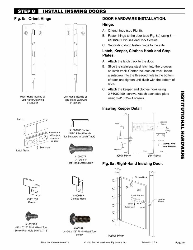
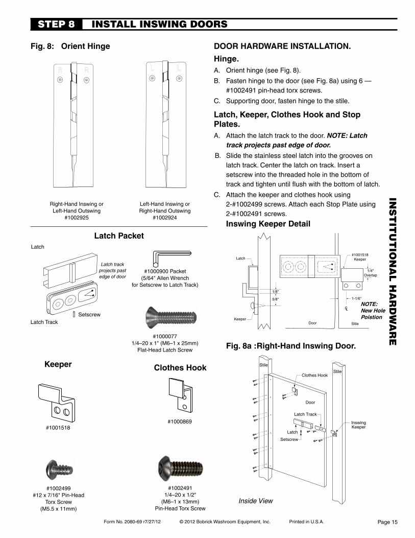
door hardWare insTallaTion.
hinge.
A. Orient hinge (see Fig. 8).
B. Fasten hinge to the door (see Fig. 8a) using 6 — #1002491 Pin-in-Head Torx Screws .
C. Supporting door, fasten hinge to the stile.
latch, keeper, clothes hook and stop plates.
A. Attach the latch track to the door.
B. Slide the stainless steel latch into the grooves on latch track. Center the latch on track. Insert a setscrew into the threaded hole in the bottom of track and tighten until flush with the bottom of latch.
C. Attach the keeper and clothes hook using 2-#1002499 screws. Attach each stop plate using 2-#1002491 screws.
Fig. 8a : right-hand inswing door.
INSTALL INSwING DOORS
Inside View
#10024911/4–20 x 1/2" Pin-in-Head Torx
Screw
#10000771/4–20 x 1"
Flat-Head Latch Screw
#1001518Keeper
Latch TrackSetscrew
#1000900 Packet(5/64" Allen Wrench
for Setscrew to Latch Track)
Latch track will projectpast edge
of door
Latch
Left-Hand Inswing orRight-Hand Outswing
#1002920
Right-Hand Inswing or Left-Hand Outswing
#1002921
Fig. 8: orient hinge
#1002499#12 x 7/16" Pin-in-Head Torx
Screw Pilot Hole 3/16" x 7/16"
Latch
KeeperDoor Stile
1/8''
5/8'' 1-1/6''
CL
1/4''Overlap
#1001518Keeper
Side View
inswing keeper detail
Flat View
#1000869Clothes Hook
NOTE: New Hole Postion
INS
TIT
UT
ION
AL
HA
RD
wA
RE
Page 15
Form No. 1080-69 r08/03/12 © 2012 Bobrick Washroom Equipment, Inc. Printed in U.S.A.
Clothes HookUpper Hinge
Lower Hinge
Setscrew
Latch
Latch Track
Outswing Keeper& Optional Doorstop
Stile
Stile
Door
Cam
#1000312Packet
9/16'' (14mm)
CL
PerpendicularStile 7/16''
(11mm)Min.
#1000192Keeper is on
Same as LatchCL
Door
#1002666Sex Bolt
#1002665Button Head Screws-5/8''
#10000771/4–20 x 1"
Flat-Head Latch Screw
keepers
doorhandle
(2)
#1002023Front Entry
#1000869
#1000192Alcove
Fig.9a: Right-HandOutswingDoor.
#1000900 Packet(5/64" Allen Wrench tosetscrew to latch track)
Fig.9b: OutswingDoorkeeper on perpendicular stile (alcove layout)
#1000418Accessible Toilet
Compartment Label
latch packet
Latch Track
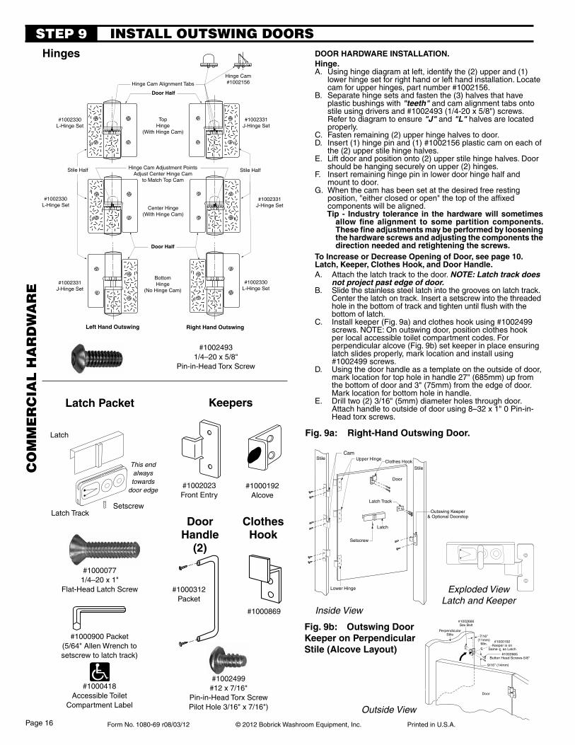
INSTALL OUTSwING DOORSSTEp 9
clotheshook
Latch
Inside View
Outside View
Setscrew
#10024931/4–20 x 5/8"
Pin-in-Head Torx Screw
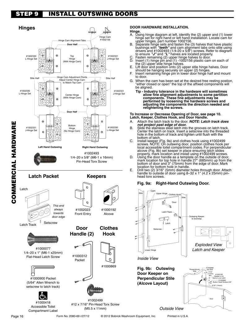
door hardWare insTallaTion.hinge.A. Using hinge diagram at left, identify the (2) upper and (1)
lower hinge set for right hand or left hand installation. Locate cam for upper hinges, part number #1002156.
B. Separate hinge sets and fasten the (3) halves that have plastic bushings with "teeth" and cam alignment tabs onto stile using drivers and #1002493 (1/4-20 x 5/8") screws. Refer to diagram to ensure "J" and "L" halves are located properly.
C. Fasten remaining (2) upper hinge halves to door.D. Insert (1) hinge pin and (1) #1002156 plastic cam on each of
the (2) upper stile hinge halves.E. Lift door and position onto (2) upper stile hinge halves. Door
should be hanging securely on upper (2) hinges.F. Insert remaining hinge pin in lower door hinge half and
mount to door.G. When the cam has been set at the desired free resting
position, "either closed or open" the top of the affixed components will be aligned. Tip - industry tolerance in the hardware will sometimes
allow fine alignment to some partition components.Thesefineadjustmentsmaybeperformedbylooseningthe hardware screws and adjusting the components the direction needed and retightening the screws.
ToIncreaseorDecreaseOpeningofDoor,seepage10.latch, keeper, clothes hook, and door handle.A. Attach the latch track to the door. NOTE: Latch track does
not project past edge of door.B. Slide the stainless steel latch into the grooves on latch track.
Center the latch on track. Insert a setscrew into the threaded hole in the bottom of track and tighten until flush with the bottom of latch.
C. Install keeper (Fig. 9a) and clothes hook using #1002499 screws. NOTE: On outswing door, position clothes hook per local accessible toilet compartment codes. For perpendicular alcove (Fig. 9b) set keeper in place ensuring latch slides properly, mark location and install using #1002499 screws.
D. Using the door handle as a template on the outside of door, mark location for top hole in handle 27" (685mm) up from the bottom of door and 3" (75mm) from the edge of door. Mark location for bottom hole in handle.
E. Drill two (2) 3/16" (5mm) diameter holes through door. Attach handle to outside of door using 8 –32 x 1" 0 Pin-in-Head torx screws.
hinges
Exploded ViewLatch and Keeper
#1002499#12 x 7/16"
Pin-in-Head Torx ScrewPilot Hole 3/16" x 7/16")
This end always towards
door edge
Door Half
Center Hinge(With Hinge Cam)
#1002331J-Hinge Set
#1002330L-Hinge Set
#1002331J-Hinge Set
Left Hand Outswing
#1002330L-Hinge Set
Door Half
TopHinge
(With Hinge Cam)
Hinge Cam#1002156Hinge Cam Alignment Tabs
Stile HalfStile Half
Right Hand Outswing
#1002331J-Hinge Set
#1002330L-Hinge Set
Hinge Cam Adjustment PointsAdjust Center Hinge Cam
to Match Top Cam
BottomHinge
(No Hinge Cam)
CO
mm
ER
CIA
L H
AR
Dw
AR
E
Page 16
Form No. 1080-69 r08/03/12 © 2012 Bobrick Washroom Equipment, Inc. Printed in U.S.A.
Door Stile
1/4''
1/2''
CL
STEp 9
#10024911/4–20 x 1/2" Pin-in-Head Torx
Screw
#10000771/4–20 x 1" Flat-Head Latch Screw
keeper
doorhandle
(2)
#1002023
Fig.9a:Right-HandOutswingDoor.
#1000900 Packet(5/64" Allen Wrench for
Setscrew to Latch Track)
#1000312Packet
#1000418Accessible Toilet
Compartment Label
latch packet
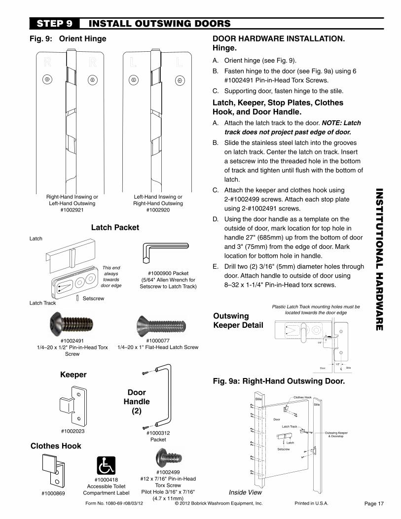
INSTALL OUTSwING DOORS
door hardWare insTallaTion.hinge.
A. Orient hinge (see Fig. 9).
B. Fasten hinge to the door (see Fig. 9a) using 6 #1002491 Pin-in-Head Torx Screws.
C. Supporting door, fasten hinge to the stile.
latch, keeper, stop plates, clothes hook, and door handle.A. Attach the latch track to the door. NOTE: Latch
track does not project past edge of door.
B. Slide the stainless steel latch into the grooves on latch track. Center the latch on track. Insert a setscrew into the threaded hole in the bottom of track and tighten until flush with the bottom of latch.
C. Attach the keeper and clothes hook using 2-#1002499 screws. Attach each stop plate using 2-#1002491 screws.
D. Using the door handle as a template on the outside of door, mark location for top hole in handle 27" (685mm) up from the bottom of door and 3" (75mm) from the edge of door. Mark location for bottom hole in handle.
E. Drill two (2) 3/16" (5mm) diameter holes through door. Attach handle to outside of door using
8 –32 x 1-1/4" Pin-in-Head torx screws.
Setscrew
Latch
Latch Track
Outswing Keeper& Doorstop
Stile
Door
Stile Clothes Hook
Fig.9: OrientHinge
Latch Track
Latch
Left-Hand Inswing orRight-Hand Outswing
#1002920
Right-Hand Inswing or Left-Hand Outswing
#1002921
Setscrew
#1002499#12 x 7/16" Pin-in-Head
Torx ScrewPilot Hole 3/16" x 7/16"
(4.7 x 11mm)
This end always towards
door edge
outswingkeeper detail
Plastic Latch Track mounting holes must be located towards the door edge
Inside View#1000869
clothes hook
INS
TIT
UT
ION
AL
HA
RD
wA
RE
Page 17
Form No. 1080-69 r08/03/12 © 2012 Bobrick Washroom Equipment, Inc. Printed in U.S.A.
3/4'' Thick Stile
5/16'' Wide Flange for 3/4'' Thick Stile
1. Close
Shoe Retainer
Flat Washer at Floor or Ceiling
Retaining Screw Fasten When Closed
2. Close
to Engage Retainer
1. Push on Retaining Clip to Engage with Hole
This End to Wall
Anchor Bolt, Nuts & Washers
Shoe
Trap Bottom Flange Under Shoe Retainer
3/4'' Thick Stile
5/16'' Wide Flange for 3/4'' Thick Stile
Shoe Retainer
Flat Washer at Floor or Ceiling
Anchor Bolt, Nuts & Washers
Shoe
Trap Bottom Flange Under Shoe Retainer
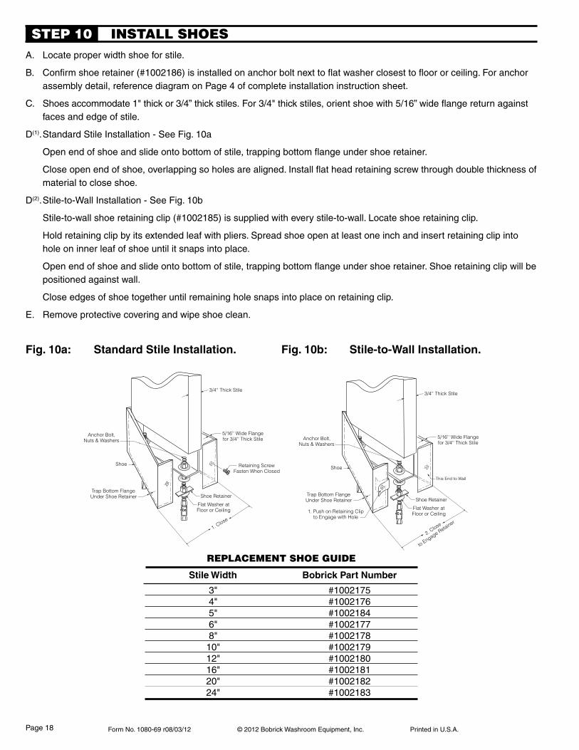
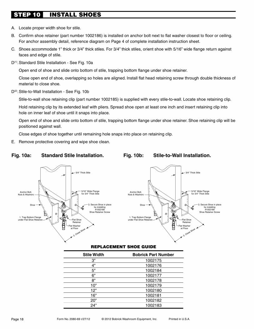
A. Locate proper width shoe for stile.
B. Confirm shoe retainer (#1002186) is installed on anchor bolt next to flat washer closest to floor or ceiling. For anchor assembly detail, reference diagram on Page 4 of complete installation instruction sheet.
C. Shoes accommodate 1" thick or 3/4” thick stiles. For 3/4" thick stiles, orient shoe with 5/16” wide flange return against faces and edge of stile.
D(1). Standard Stile Installation - See Fig. 10a
Open end of shoe and slide onto bottom of stile, trapping bottom flange under shoe retainer.
Close open end of shoe, overlapping so holes are aligned. Install flat head retaining screw through double thickness of material to close shoe.
D(2). Stile-to-Wall Installation - See Fig. 10b
Stile-to-wall shoe retaining clip (#1002185) is supplied with every stile-to-wall. Locate shoe retaining clip.
Hold retaining clip by its extended leaf with pliers. Spread shoe open at least one inch and insert retaining clip into hole on inner leaf of shoe until it snaps into place.
Open end of shoe and slide onto bottom of stile, trapping bottom flange under shoe retainer. Shoe retaining clip will be positioned against wall.
Close edges of shoe together until remaining hole snaps into place on retaining clip.
E. Remove protective covering and wipe shoe clean.
INSTALL SHOESSTEp 10
Fig.10a: StandardStileInstallation. Fig.10b: Stile-to-WallInstallation.
REpLACEmENT SHOE GUIDE
stile Width Bobrick part number
3" #1002175 4" #1002176 5" #1002184 6" #1002177 8" #1002178 10" #1002179 12" #1002180 16" #1002181 20" #1002182 24" #1002183
Page 18
Form No. 1080-69 r08/03/12 © 2012 Bobrick Washroom Equipment, Inc. Printed in U.S.A.
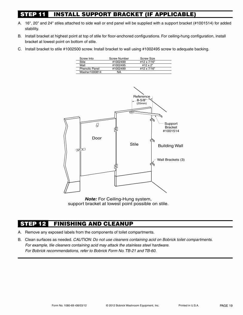
A. Remove any exposed labels from the components of toilet compartments.
B. Clean surfaces as needed. CAUTION: Do not use cleaners containing acid on Bobrick toilet compartments. For example, tile cleaners containing acid may attack the stainless steel hardware. For Bobrick recommendations, refer to Bobrick Form No. TB-21 and TB-60.
FINISHING AND CLEANUpSTEp 12
INSTALL SUppORT BRACkET (IF AppLICABLE)STEp 11A. 16", 20" and 24" stiles attached to side wall or end panel will be supplied with a support bracket (#1001514) for added
stability.
B. Install bracket at highest point at top of stile for floor-anchored configurations. For ceiling-hung configuration, install bracket at lowest point on bottom of stile.
C. Install bracket to stile #1002500 screw. Install bracket to wall using #1002495 screw to adequate backing.
SupportBracket
#1001514
Door
Stile
Wall Brackets (3)
Building Wall
Note: For Ceiling-Hung system,support bracket at lowest point possible on stile.
Reference8-5/8"(20mm)
Screw Into Screw Number Screw SizeStile #1002499 #12 x 7/16"Wall #1002495 #12 x 2"Phenolic Panel #1002499 #12 x 7/16"Washer 1000814 NA
PAGE 19
Form No. 1080-69 r08/03/12 © 2012 Bobrick Washroom Equipment, Inc. Printed in U.S.A.
in the United states: BoBrick WashrooM eQUipMenT, inc.200CommerceDrive,CliftonPark,NY12065-1350,Telephone:(518)877-7444•FAX:518-877-5029
11611HartStreet,NorthHollywood,CA91605-5882:(818)982-9600•FAX:818-503-9287or email [email protected]
in canada: BoBrick WashrooM eQUipMenT coMpanY45RolarkDrive,Scarborough,OntarioM1R3B1•FAX:(877)423-8555
7 16954 00911 1
1080-69
Form No. 2080-69 r7/27/12 © 2012 Bobrick Washroom Equipment, Inc. Printed in U.S.A.
FLOORANCHORED
INSTALLATION INSTRUCTIONSmaximum privacy
solid phenolic ToileT parTiTions2080 DuraLineSeries® • 2180 DuraLineSeries® Class-A Fire Rated
Includes Institutional Hardware Option .67
OVERHEADBRACED
CEILINGHUNG
FLOOR-TO- CEILING
ANCHORED
IMPORTANT:
Storage and Handling Information on last page.
Review these instructions thoroughly prior to
installation.
Form No. 2080-69 r/27/12 © 2012 Bobrick Washroom Equipment, Inc. Printed in U.S.A.
pre-insTallaTion.
A. Structural support in walls and floors is not furnished by Bobrick. Confirm that adequate backing is present in wall, ceilings, and floors prior to installation.
B. This installation booklet must be used with the Bobrick layout sheets.
C. You may verify hardware receipt by cross-referencing the last page of the layout sheets against the box contents.
insTallaTion sTeps.
1. Lay Out All Anchor Locations ............................ Page 3
2. Install All Anchors ............................................. Page 4
3. Install Wall Brackets .......................................... Page 7
4. Position Panels .................................................. Page 9
5. Install Stile-To-Panel Brackets ........................... Page 9
6. Install Stiles ..................................................... Page 11
7. Install Headrail (if applicable) .......................... Page 12
8. Install Inswing Doors ....................................... Page 13
9. Install Outswing Doors .................................... Page 15
10. Install Shoes ................................................... Page 17
11. Finishing And Cleanup .................................... Page 18
A. Organize components with
appropriate hardware.
B. When calculating distances to centerlines, stiles, and doors are 3/4" (19mm) thick; panels are 1/2" (13mm) thick.
C. Look for panel-to-stile offsets indicated on the layout sheets.
D. Pilot hole sizes vary by application. Read all directions carefully and use a drill stop to ensure you do not drill through material in error.
E. Doors are not pre-drilled for clothes hooks.
F. On inswing doors the latch track projects past the edge of door to act as a doorstop.
G. Keepers are not drilled to allow easier stile leveling.
H. Remove debree from all drilled holes.
pREpARATION
recommended Tools.
CAUTION: Be sure to use proper safety gear.
1. Chalk Line
2. Plumb-bob
3. Masking Tape (for laying out holes on floors/walls/ceilings to be drilled)
4. Tape Measure and Pencils
5. Center Punch
6. Electric and/or Battery-Powered Drill
7. Drill Bits #19 (.166") M4.2 3/16" (4.7mm)
3/8" (9.5mm) for Concrete/Masonry 7/16" (11mm)
8. Screwdrivers/Screwdriver Bits flathead and phillips, #2 and #3
9. Pin-Head Torx Screw Driver – (to install door hardware) – Supplied by Bobrick
10. Shims
11. Adjustable Supports 1-1/2" to 12" (40–105mm)
12. Level
13. Wrench – adjustable 9/16" (14mm) open end (2 reqd. for adjusting hex nuts on anchors)
14. Allen Wrench – 5/64" (2mm) (to install door latch)—Supplied
by Bobrick.
15. Hack Saw
16. Hammer
17. Safety GlassesPage 2
Form No. 2080-69 r7/27/12 © 2012 Bobrick Washroom Equipment, Inc. Printed in U.S.A.
CLStileCenterline
X
Y
3/8''(10mm)
CLPanel CenterlinesCL
CLPanelCenterline
XY
CL StileCenterline
CLStileCenterline
PanelCenterline
X Y1/2''
(50mm)1/4''
(75mm)
3/8''(10mm)
CL CL
XY
CLPanel Centerline
PanelCenterline
CL StileCenterline
Stile Size(width)
Y X
Leveling Bar
Solid PhenolicCore
X
Page 3
Fig. 1a: Floor-anchored or ceiling-hung Front-entry corner layout.
Fig. 1b: overhead-Braced alcove closed layout.
A. Refer to Bobrick layout sheets for component locations on your specific application.
B. From back wall, measure and mark the location of the stile centerline. Stile centerline = 3/8" (10mm) + panel length + gaps specified on layout sheets.
C. From side wall at centerline of stile, measure dimensions for floor or ceiling anchors according to layout sheet. Refer to drilling table below for center-to-center distances between anchors. Centerline of floor anchor from edge of stile is 5/8" (16mm); dimension on 3" (8cm) stile is 1-1/2" (38mm).
layouT examples.
Fig. 1d: Floor-anchored or ceiling-hung alcove open layout.
Fig. 1c: Floor-anchored or ceiling-hung alcove closed layout.
Fig. 1e: detail of Typical stile
NOTE: 16", 20", 24" (41, 51, 61cm) stiles have 2 leveling bars. Use the 2 outside slots for the 2 anchors.
LAY OUT ALL ANCHOR LOCATIONS
NOTE: The center stile is perpendicular to panel.
NOTE: The stiles are in-line with panel. NOTE: The center stile is perpendicular to panel.
STEp 1
LEGEND: Obtain Dimension from Bobrick Layout Sheet.
drilling TaBle For drilling Floor or ceiling anchors
stile size (width)
no. ofholes
xdim.
ydim.
3'' (8cm) 1 1½'' (38mm) —
4'' (10cm) 2 5/8'' (16mm) 2¾'' (7cm)
5'' (13cm) 2 5/8'' (16mm) 3¾'' (10cm)
6'' (15cm) 2 5/8'' (16mm) 4¾'' (12cm)
8'' (20cm) 2 5/8'' (16mm) 6¾'' (17cm)
10'' (25cm) 2 5/8'' (16mm) 8¾'' (22cm)
12'' (30cm) 2 5/8'' (16mm) 10¾'' (27cm)
16'' (41cm) 2 5/8'' (16mm) 14¾'' (38cm)
20'' (51cm) 2 5/8'' (16mm) 18¾'' (48cm)
24'' (61cm) 2 5/8'' (16mm) 22¾'' (58cm)
Form No. 2080-69 r/27/12 © 2012 Bobrick Washroom Equipment, Inc. Printed in U.S.A.
Flat Washer
Hex NutHex Nut
Flat Shoe Retainer
Wedge Anchor
2-1/8'' to 2-1/4''(54 to 60mm)
1-5/8'' to 1-3/4''(41 to 44mm)
Flat Washer
Leveling Bar
Install whenstile is placedon anchor bolts.
Flat Washer
Hex NutLock Washer
1'' Ref.(25mm)
or asRequired
2''50mm
Hex NutFlat Shoe Retainer
Wedge Anchor1-7/8''
(48mm)
Flat Washer
Hex Nut
Page 4
A. Drill a 3/8" (9.5mm) hole to 2" (50mm) minimum depth.
B. Remove all loose material/debris from hole.
C. Add Flat Washer, Flat Shoe Retainer, Hex Nut to Wedge Anchor so that Flat Washer is 1-7/8’’ (48mm) from the bottom of the anchor to ensure proper installation depth. Thread 2nd Hex Nut loosely to top of Anchor to prevent stripping or damaging threads during installation.
D. Insert Anchor into hole with threaded end up. Use hammer to drive the Anchor into hole until Flat Washer is flush with concrete surface (depth set in STEP C).
E. Use Wrench to tighten Hex Nut until anchor is firmly set (2-4 full turns past finger tight position). Anchor bolt will move up approx. 1/16" (1.6mm) for every full turn of Hex Nut.
F. Spin down top Hex Nut. Add Flat Washer.
Hints/Notes: •3/8"x2"(M9.5x50mm)holeneededtoinstall1002701FloorAnchor.Useconcrete/masonrydrillbit. •FloorAnchorsforwoodfloorsareavailableuponrequest.
Tools Needed: •Hammer •Drill •3/8"(9.5mm)Concrete/MasonryBit •Wrench(adjustableorwith9/16"openend
Fig. 2a: Finished detail of Floor anchor.
side view1002701
Floor Anchor
Fig. 2b: Floor anchor attached to stile.(3-dimensional view)
Top side view
INSTALL FLOOR ANCHORSSTEp 2
NOTE: Do NOT add 3rd Hex Nut, Lock Washer, and 3rd Flat Washer until stiles are attached to Floor Anchor.
Parts Needed: •1002701FloorAnchorPacket (includes: 3 Hex Nuts, 3 Flat Washers, Wedge Anchor, Lock Washer, Flat Shoe Retainer)
Form No. 2080-69 r7/27/12 © 2012 Bobrick Washroom Equipment, Inc. Printed in U.S.A.
FinishedCeiling
Hex NutSplit Lock Washer
Bevel Washer
Hex Nut
StructuralBeam
SpacerFlat Shoe Retainer
Hex Nuts
Flat Washers
Split Lock Washer
Leveling Bar
Threaded Rod
Hex Nut
1'' Ref.(25mm)
or asRequired
Page 5
ceiling anchors.
NOTE: Ceiling anchors are to be installed before finished ceiling is applied. All structural framing is to be furnished by others. For Bobrick recommendations, refer to Bobrick Form No. TB-32.
A. Drill 7/16" (11mm) diameter hole through structural beam. Insert threaded rod through hole in beam. Rod is furnished standard 6" (150mm) length. Longer rods should be purchased locally if required.
B. Drop a bevel washer and lock washer over rod. Screw on one hex nut.
C. Install second hex nut against bottom of beam and tighten.
D. Install spacer, shoe retainer, and a third hex nut. Make sure shoe retainer is in proper position to accept shoe (see Fig. 2c or 10a for proper shoe retainer position).
E. Install remaining flat washers (2), lock washer (1), and hex nuts (2), as shown in Fig. 2c.
F. Repeat process for each ceiling anchor.
Fig. 2c: detail of ceiling anchor.
INSTALL ALL ANCHORSSTEp 2
Form No. 2080-69 r/27/12 © 2012 Bobrick Washroom Equipment, Inc. Printed in U.S.A.
F-bracketQty. (3)
Y-bracketQty. (3) U-bracket
Qty. (3)
L-bracketQty. (3)
Y-bracketQty. (3)
Y-bracketQty. (3)
1000974Y-bracket
Qty. (3)
Alcove bracketQty. (3)
Y-bracketQty. (3)
F-bracketQty. (3)
Alcove bracketQty. (3)
F-bracketQty. (3)
Y-bracketQty. (3)
L-bracketQty. (3)
Y-bracketQty. (3)
F-bracketQty. (3)
U-bracketQty. (3)
Page 6
BRACkETS AND SCREwS
#1000975Internal Panel to Wall
F-bracket
#1000972Internal Panel to Stile
u-bracket
#1000974External Panel or Stile
to Wall or Panel
y-bracket
#1000351External Panel to Stile
l-bracket
overhead-Braced alcove open layout and adjoining Front-entry stall.overhead-Braced alcove closed layout.
Front-entry corner layout.
NOTE: Adequate wall backing is required. High-quality drill bit is suggested for drilling into solid phenolic material.
example BrackeT applicaTions.
#1002495#12 x 2" (M5.5 x 50mm)
Wall Screws
• 3/16''x7/16"(4.7 x 11mm)• Forattachmentofbracketstopanelsandstiles.• Donotthrough-drill.
• #19(.166)x2"(50mm)• Forattachmentofallwallbracketstostud backing.
pilot hole sizes—
NOTE: The stile is perpendicular to panel. No hardware is exposed on the outside of stall.
Floor-anchored or ceiling-hungalcove closed layout.
NOTE: The stile is in-line with panel.No hardware is exposed on the outside of stall.
#1000282Panel-In-line with Stile
alcove bracket
NOTE:U- and F-brackets are used on internal panels only, where there is an adjoining stall to conceal the hardware.
#1002499#12 x 7/16" Pin-Head Torx Screw(M5.5 x 11mm) Panel/Stile Screw
CO
mm
ER
CIA
L H
AR
Dw
AR
E
Form No. 2080-69 r7/27/12 © 2012 Bobrick Washroom Equipment, Inc. Printed in U.S.A.
2"
1"
2"
1"
2"
1"
1
22
1 1
1
3
4 2
11
Page 7
1 2 — 1002387 Angle Bracket 10 — 1002495 Wall Screw 10 — 1002499 Panel/Stile Screw
2 1 — 1002388 U-Channel Bracket 15 — 1002499 Panel Screw
3 1 — 1002389 Strip Bracket 10 — 1002499 Stile/Panel Screw
4 2 — 1002387 Angle Bracket 20 — 1002499 Stile/Panel Screw
BRACkETS AND SCREwS
#10023872 each for:
Stile-to-WallPanel-to-Wall
angle Bracket
#1002389Panel In-Line with Stile
strip Bracket
#1002388Panel-to-Stile
Panel-to-Wall (optional)
u-channel Bracket
alcove closed layout and adjoining Front-entry stall.
Front-entry corner layout.example BrackeT applicaTions.
#1002495#12 x 2" Pin-Head Torx Screw
(M5.5 x 50mm)Wall Screw
#1002499#12 x 7/16" Pin-Head Torx Screw
(M5.5 x 11mm)Panel/Stile Screw Channel to Stile Screw
pilot hole sizes—
3/16" x 7/16" (4.7 x 11mm) #19 (.166) x 2'' (50mm)
NOTE: Adequate wall backing is required. High-quality drill bit is suggested for drilling into solid phenolic material.
Form No. 2080-69 r/27/12 © 2012 Bobrick Washroom Equipment, Inc. Printed in U.S.A.
72''(183cm)
PanelCenterlines
Floor Anchors
8''(20cm)
40''(102cm)
70''(177cm)
41''(104cm)
8''(20cm)
72''(183cm)
8''(20cm)
Panel Centerline
70'(177cm)
41''(104cm)
Floor Anchors 8''(20cm)
StileCenterline
40''(102cm)
72''(183cm)
8''(20cm)
Panel Centerline
72''(183cm)
Floor Anchors
Panel Centerline
8''(20cm)
40''(102cm)
40''(102cm)
Page 8
A. Measure and mark the locations of centerlines for all the stiles and panels on walls.
B. Using the wall brackets as templates, measure and mark the location of all mounting holes plumb, according to dimensions shown in illustrations (Fig. 3a, 3b, 3c).
C. Use #19 (.166) drill bit for 2" (50mm) deep pilot holes into adequate wall backing.
D. Secure wall brackets with #1002495 screws.
These mounting points require wall backing.
Obtain dimension from Bobrick Layout Sheet
INSTALL wALL BRACkETSSTEp 3
Fig. 3a: Front-entry corner
Fig. 3b: overhead-Braced or Floor-to-ceiling anchored alcove closed layout.
Fig. 3c: Floor-anchored or ceiling-hung alcove open layout.
CAUTION: Panel centerline is not always on the stile centerline. Refer to Bobrick Layout Sheets for panel offsets.
CO
mm
ER
CIA
L H
AR
Dw
AR
E
Form No. 2080-69 r7/27/12 © 2012 Bobrick Washroom Equipment, Inc. Printed in U.S.A.
PanelCenterlines
Floor Anchors
74-1/8''(46cm)
39-3/4''(131cm)
56-7/8''(144cm)
3/4''(19mm)
12-1/8''(31cm)
To bottom of angle
22-1/2''(57cm)
5-3/8''(14cm)
StileCenterline
74-1/8''(188cm)
22-1/2''(57cm)
56-7/8''(144cm)
4-1/2''(12cm)
To bottom of angle
39-3/4''(101cm)
5-3/8''(14cm)
74-1/8''(188cm)
Panel Centerline
FloorAnchors
StileCenterline
22-1/2''(57cm)
39-3/4''(101cm)
74-1/8''(188cm)
4-1/2''(12cm)
To bottom of angle
7/8''(22mm)
3/4''(19mm)
4-1/2''(12cm)
To bottom of angle
56-7/8''(144cm)
39-3/4''(101cm)
5-3/8''(14cm)
39-3/4''(101cm)
22-1/2''(57cm)
5-3/8''(14cm)
4-1/2''(12cm)
To bottomof panel
Page 9
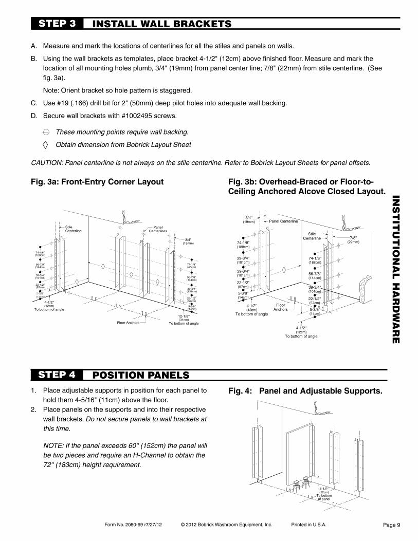
A. Measure and mark the locations of centerlines for all the stiles and panels on walls.
B. Using the wall brackets as templates, place bracket 4-1/2" (12cm) above finished floor. Measure and mark the location of all mounting holes plumb, 3/4" (19mm) from panel center line; 7/8" (22mm) from stile centerline. (See fig. 3a).
Note: Orient bracket so hole pattern is staggered.
C. Use #19 (.166) drill bit for 2" (50mm) deep pilot holes into adequate wall backing.
D. Secure wall brackets with #1002495 screws.
INSTALL wALL BRACkETSSTEp 3
Fig. 3a: Front-entry corner layout
1. Place adjustable supports in position for each panel to hold them 4-5/16" (11cm) above the floor.
2. Place panels on the supports and into their respective wall brackets. Do not secure panels to wall brackets at this time.
Fig. 4: panel and adjustable supports.
STEp 4 pOSITION pANELS
CAUTION: Panel centerline is not always on the stile centerline. Refer to Bobrick Layout Sheets for panel offsets.
Fig. 3b: overhead-Braced or Floor-to-ceiling anchored alcove closed layout.
These mounting points require wall backing.
Obtain dimension from Bobrick Layout Sheet
NOTE: If the panel exceeds 60'' (152cm) the panel will be two pieces and require an H-Channel to obtain the 72'' (183cm) height requirement.
INS
TIT
UT
ION
AL
HA
RD
wA
RE
Form No. 2080-69 r/27/12 © 2012 Bobrick Washroom Equipment, Inc. Printed in U.S.A.
70''(177cm)
41''(104cm)
8''(20cm)
72''(183cm)
8''(20cm)
4-5/16''(11cm)
40''(102cm)
Panel Centerline
83''(211cm)
12''(30cm)
76''(193cm)
44''(112cm)
Panel Centerline
4''(10cm)
75-5/16''(191cm)
36''(91cm)
68''(173cm)
29''(74cm)
33''(84cm)
8''(20cm)
72''(183cm)
AsRequired
Up to10'0''
(305cm)
12''(30cm)
Page 10
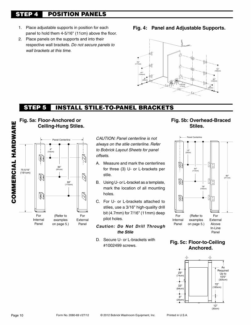
1. Place adjustable supports in position for each panel to hold them 4-5/16" (11cm) above the floor.
2. Place panels on the supports and into their respective wall brackets. Do not secure panels to wall brackets at this time.
Fig. 4: panel and adjustable supports.
Fig. 5a: Floor-anchored or ceiling-hung stiles.
Fig. 5b: overhead-Braced stiles.
CAUTION: Panel centerline is not always on the stile centerline. Refer to Bobrick Layout Sheets for panel offsets.
A. Measure and mark the centerlines for three (3) U- or L-brackets per stile.
B. Using U- or L-bracket as a template, mark the location of all mounting holes.
C. For U- or L-brackets attached to stiles, use a 3/16" high-quality drill bit (4.7mm) for 7/16" (11mm) deep pilot holes.
Caution: Do Not Drill Through the Stile
D. Secure U- or L-brackets with #1002499 screws.
ForInternalPanel
ForExternal
Panel
STEp 4 pOSITION pANELS
INSTALL STILE-TO-pANEL BRACkETSSTEp 5
ForInternalPanel
ForExternalAlcoveIn-LinePanel
(Refer to examples
on page 5.)
(Refer to examples
on page 5.)
Fig. 5c: Floor-to-ceiling anchored.
CO
mm
ER
CIA
L H
AR
Dw
AR
E
Form No. 2080-69 r7/27/12 © 2012 Bobrick Washroom Equipment, Inc. Printed in U.S.A.
Panel Centerline
84''(213cm)
17-1/4''(46cm)
17-1/4''(46cm)
17-1/4''(46cm)
Finish Face of Floor
5/8''(16mm)
1-7/8''(47mm)
7/8''(22mm) 5-3/8''
(36cm)4-1/2''(11cm)
17-1/4''(46cm)
72''(183cm)
AsRequired
Up to10' 0''
(305cm)
4-5/16''(11cm)
4-1/2''(11cm)
17-1/4''(46cm)
17-1/4''(46cm)
17-1/4''(46cm)
5-3/8''(14cm)
17-1/4''(46cm)
Page 11
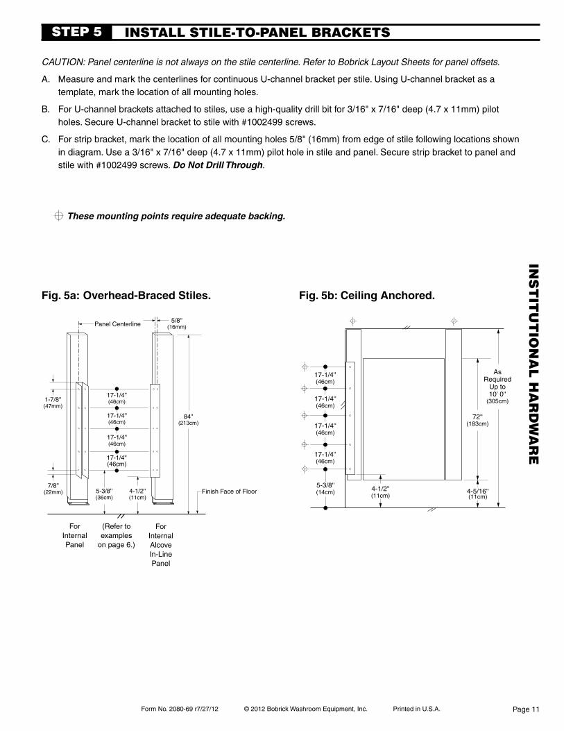
Fig. 5a: overhead-Braced stiles.
CAUTION: Panel centerline is not always on the stile centerline. Refer to Bobrick Layout Sheets for panel offsets.
A. Measure and mark the centerlines for continuous U-channel bracket per stile. Using U-channel bracket as a template, mark the location of all mounting holes.
B. For U-channel brackets attached to stiles, use a high-quality drill bit for 3/16" x 7/16" deep (4.7 x 11mm) pilot holes. Secure U-channel bracket to stile with #1002499 screws.
C. For strip bracket, mark the location of all mounting holes 5/8" (16mm) from edge of stile following locations shown in diagram. Use a 3/16" x 7/16" deep (4.7 x 11mm) pilot hole in stile and panel. Secure strip bracket to panel and stile with #1002499 screws. Do Not Drill Through.
INSTALL STILE-TO-pANEL BRACkETSSTEp 5
ForInternalPanel
ForInternalAlcoveIn-LinePanel
(Refer to examples
on page 6.)
Fig. 5b: ceiling anchored.
These mounting points require adequate backing.
INS
TIT
UT
ION
AL
HA
RD
wA
RE
Form No. 2080-69 r/27/12 © 2012 Bobrick Washroom Equipment, Inc. Printed in U.S.A.
Hex Nut
Flat WashersLock Washer
Hex Nuts
Flat Shoe Retainer
Wedge Anchor
LevelingBar
Step A
Flat Washer
AsRequired
Hex Nut
Lock Washer
Flat Washers
Hex Nut
Finished Ceiling
Page 12
A. Place the stiles onto the threaded rods of anchors. Add a flat washer, lock washer, and a third hex nut to each threaded rod of floor anchors (these should already be in place on ceiling anchors—refer back to Fig. 2a). Do not tighten hex nuts at this time.
B. Insure edge of panel is touching screw heads in brackets on stiles. Using brackets as templates, drill
3/16" x 7/16" (4.7 x 11mm) pilot holes in panel.
C. Fasten brackets to panels with #1002499 screws.
D. Use level to plumb stiles. Place shims between panels and wall.
E. Set door openings to be square, plumb and true per Bobrick layout sheet.
F. Tighten hex nuts on stile anchoring system.
G. Secure panels to wall brackets using #1002499 screws.
Fig.6b:Floor-AnchoredInstallation.
Fig.6c:Ceiling-HungInstallation.
Fig.6a:OverheadBracedInstallation.
INSTALL STILES AND SET DOOR OpENINGSSTEp 6
Obtain dimension from Bobrick Layout Sheet
Form No. 2080-69 r7/27/12 © 2012 Bobrick Washroom Equipment, Inc. Printed in U.S.A.
StileStile Panel
Front Headrail
Outswing Door
Return Headrail
Stile
Stile
Panel
Return Headrail
#1002495Wall Screw -2''
Front Headrail
#1002499Sheet-MetalScrew -7/16''
#1000927Headrail Bracket
#1000978HeadrailEnd Cap
#1002499Sheet-MetalScrew -7/16''
#1002499Sheet-MetalScrew -7/16''
#1000927Headrail Bracket
Page 13
Note: Bobrick provides headrail in 84" part #1002385 (213cm) long sections. Headrail seams must be located over stiles.
A. Measure wall-to-wall dimension less 1/4" (6mm). If it is a corner application, measure from wall to outside edge of stile less 1/8" (3mm).
B. Place headrail over stile.
C. For corner and alcove layouts, cut return headrail. Measure from the inside edge of front headrail to the back wall (See Fig. 7a and 7b).
D. Using the headrail bracket as a template, mark the location for mounting holes in walls and headrails.
E. Drill 3/16" x 3/4" (4.7 x 19mm) pilot holes into front headrail and stiles; then, at wall locations, drill #19 (.166) x 2" (50mm) pilot holes into adequate wall backing.
F. Fasten headrail bracket to front headrail with #1002499 screws and to wall with #1002495 screws.
G. Connect the return headrail to front headrail with headrail bracket and four (4) #1002499 screws.
H. For corner layouts, install #1000978 end cap to finish the corner. Using the end cap as a template, mark and drill pilot hole, then secure end cap with one (1) #1002499 screw.
I. Fasten front headrail to stile by drilling pilot hole, then secure to stile with one (1) #1002499 screw.
Fig.7b:AlcoveConfiguration.
INSTALL HEADRAIL (IF AppLICABLE) STEp 7
optional curtain Track:
#1000978
Back viewFront view
Fig.7c:DetailofEndCap.
Fig.7a:HeadrailInstallationHardware. CornerConfiguration
Curtain Carrier Hook(7 per entrance)
#1000833
Curtain Track#1000375
A. Cut curtain track to fit between stiles and fit inside of headrail.
B. In the middle of and at 2'' (50mm) from each end of the curtain track drill #25 (3.8mm) dia. holes through the curtain track and the headrail.
C. Install curtain carrier hooks into curtain track.
D. Fasten curtain track to headrail using #1000937 screws.
E. Install shower curtain.
Form No. 2080-69 r/27/12 © 2012 Bobrick Washroom Equipment, Inc. Printed in U.S.A.
Door Half
Center Hinge(With Hinge Cam)
#1002331J-Hinge Set
#1002330L-Hinge Set
#1002331J-Hinge Set
Left Hand Inswing
#1002330L-Hinge Set
Door Half
TopHinge
(With Hinge Cam)
Hinge Cam#1002156Hinge Cam Alignment Tabs
Stile HalfStile Half
Right Hand Inswing
#1002331J-Hinge Set
#1002330L-Hinge Set
Hinge Cam Adjustment PointsAdjust Center Hinge Cam
to Match Top Cam
BottomHinge
(No Hinge Cam)
Clothes Hook
Upper Hinge
Lower Hinge
Setscrew
Latch
Latch Track& Doorstop
InswingKeeper
Stile
Stile
Door
Cam
Latch
Door
PerpendicularStile
Panel
3''(75mm)Std.
3/4''(19mm)
13/16''(21mm)
CL Same asLatch on Door
CL
Keeper
Page 14
#1000188Alcove
latch packet keepers
clothes hook
Fig. 8b: inswing door keeper on perpendicular stile (alcove layout).
#1000180Front Entry
#1000869
Latch Track
Setscrew
#1000900 Packet(5/64" Allen Wrench for
Setscrew to Latch Track)
INSTALL INSwING DOORSSTEp 8
Latch
Inside View
hinges
#10024931/4–20 x 5/8" (M6–1 x 16mm)
Pin-Head Torx Screw
door hardWare insTallaTion.hinge.A. Using hinge diagram at left, identify the (2) upper and (1) lower
hinge set for right hand or left hand installation. Locate cam for upper hinges, part number 1002156.
B. Separate hinge sets and fasten the (3) halves that have plastic bushings with "teeth" and cam alignment tabs onto stile using driver and #1002493 (1/4-20 x 5/8") screws. Refer to diagram to ensure "J" and "L" halves are located properly.
C. Fasten (2) upper hinge halves to door.D. Insert (1) hinge pin and (1) -1002156 plastic cam on each of the (2)
upper stile hinge halves.E. Lift door and position onto (2) upper stile hinge halves. Door should
be hanging securely on upper (2) hinges.F. Insert remaining hinge pin in lower door and mount hinge half to
door.G. When the cam has been set at the desired free resting postion,
"either closed or open" the top of the affixed components will be aligned.Tip - industry tolerance in the hardware will sometimes allow
finealignmentadjustmentstosomepartitioncomponents.Thesefineadjustmentsmaybeperformedbylooseningthe hardware screws and adjusting the components the direction needed and retightening the screws.
To increase or decrease opening of door.
A. Alignment tabs have been formed into the cam and plastic hinge bushing.
B Lift door to limit of upward travel (approximately 1/2"). While door is lifted, raise cam above bottom bushing and rotate so alignment tabs meet. Ensure both upper hinges are set to same alignment tab.
C. To set door in open position, rotate cams toward door opening direction.
D. To set door in closed position, rotate cams toward door closing direction.
E. Door may not function properly if cam and bushing tabs on both hinges are not aligned properly.
latch, keeper, and clothes hook.A. Attach the latch track to the door. NOTE: Latch track projects past
edge of door and acts as doorstop.B. Slide the stainless steel latch into the grooves on latch track. Center
the latch on track. Insert a setscrew into the threaded hole in the bottom of track and tighten until flush with the bottom of latch.
C. Attach the keeper (see Fig. 8a and 8b) and clothes hook using driver and #1002499 screws.
Fig. 8a: right-hand inswing door.
Inside View
#1002499#12 x 7/16" Pin-Head Torx Screw
(M5.5 x 11mm)
#10000771/4–20 x 1" (M6–1 x 25mm)
Flat-Head Latch Screw
Latch track projects past edge of door
CO
mm
ER
CIA
L H
AR
Dw
AR
E
Form No. 2080-69 r7/27/12 © 2012 Bobrick Washroom Equipment, Inc. Printed in U.S.A.
Latch
KeeperDoor Stile
1/8''
5/8'' 1-1/6''
CL
1/4''Overlap
#1001518Keeper
Stile
Stile
Door
Setscrew
Latch
Latch Track
InswingKeeper
Clothes Hook
Page 15
STEp 8
door hardWare insTallaTion.
hinge.A. Orient hinge (see Fig. 8).
B. Fasten hinge to the door (see Fig. 8a) using 6 — #1002491 pin-head torx screws.
C. Supporting door, fasten hinge to the stile.
latch, keeper, clothes hook and stop plates.A. Attach the latch track to the door. NOTE: Latch
track projects past edge of door.
B. Slide the stainless steel latch into the grooves on latch track. Center the latch on track. Insert a setscrew into the threaded hole in the bottom of track and tighten until flush with the bottom of latch.
C. Attach the keeper and clothes hook using 2-#1002499 screws. Attach each Stop Plate using 2-#1002491 screws.
Fig. 8a : right-hand inswing door.
INSTALL INSwING DOORS
Inside View
#10024911/4–20 x 1/2"
(M6–1 x 13mm)Pin-Head Torx Screw
#10000771/4–20 x 1" (M6–1 x 25mm)
Flat-Head Latch Screw
latch packet
keeper
#1001518
Latch TrackSetscrew
#1000900 Packet(5/64" Allen Wrench
for Setscrew to Latch Track)
Latch track projects past edge of door
Latch
Left-Hand Inswing orRight-Hand Outswing
#1002924
Right-Hand Inswing or Left-Hand Outswing
#1002925
Fig. 8: orient hinge
#1002499#12 x 7/16" Pin-Head
Torx Screw(M5.5 x 11mm)
inswing keeper detail
clothes hook
#1000869
noTe:new holepoistion
INS
TIT
UT
ION
AL
HA
RD
wA
RE
Form No. 2080-69 r/27/12 © 2012 Bobrick Washroom Equipment, Inc. Printed in U.S.A.
Door Half
Center Hinge(With Hinge Cam)
#1002331J-Hinge Set
#1002330L-Hinge Set
#1002331J-Hinge Set
Left Hand Outswing
#1002330L-Hinge Set
Door Half
TopHinge
(With Hinge Cam)
Hinge Cam#1002156Hinge Cam Alignment Tabs
Stile HalfStile Half
Right Hand Outswing
#1002331J-Hinge Set
#1002330L-Hinge Set
Hinge Cam Adjustment PointsAdjust Center Hinge Cam
to Match Top Cam
BottomHinge
(No Hinge Cam)
9/16'' (14mm)
CL
PerpendicularStile 7/16''
(11mm)Min.
#1000192Keeper is on
Same as LatchCL
Door
#1002666Sex Bolt
#1002665Button Head Screws-5/8''
Clothes HookUpper Hinge
Lower Hinge
Setscrew
Latch
Latch Track
Outswing Keeper& Doorstop
Stile
Stile
Door
Cam
Page 16
#10000771/4–20 x 1" (M6-1 x25mm)
Flat-Head Latch Screw
keepers
doorhandle (2)
#1002023Front Entry
#1000869
#1000192Alcove
Fig.9a: Right-HandOutswingDoor.
#1000900 Packet(5/64" Allen Wrench tosetscrew to latch track)
Fig.9b: Outswingdoor keeper on perpendicular stile (alcove layout)
#1000418Accessible Toilet
Compartment Label
latch packet
Latch Track
INSTALL OUTSwING DOORS STEp 9
clotheshook
Latch
Inside View
Outside View
Setscrew
#10024931/4–20 x 5/8" (M6-1 x 16mm)
Pin-Head Torx Screw
door hardWare insTallaTion.hinge.A. Using hinge diagram at left, identify the (2) upper and (1) lower
hinge set for right hand or left hand installation. Locate cam for upper hinges, part number 1002156.
B. Separate hinge sets and fasten the (3) halves that have plastic bushings with "teeth" and cam alignment tabs onto stile using drivers and #1002493 (1/4-20 x 5/8") screws. Refer to diagram to ensure "J" and "L" halves are located properly.
C. Fasten remaining (2) upper hinge halves to door.D. Insert (1) hinge pin and (1) -1002156 plastic cam on each of
the (2) upper stile hinge halves.E. Lift door and position onto (2) upper stile hinge halves. Door
should be hanging securely on upper (2) hinges.F. Insert remaining hinge pin in lower door hinge half and mount
to door.G. When the cam has been set at the desired free resting postion,
"either closed or open" the top of the affixed components will be aligned.Tip - industry tolerance in the hardware will sometimes
allowfinealignmentadjustmentstosomepartitioncomponents.Thesefineadjustmentsmaybeperformed by loosening the hardware screws and adjusting the components the direction needed and retightening the screws.
To increase or decrease opening of door, see page 10.latch, keeper, clothes hook, and door handle.A. Attach the latch track to the door. NOTE: Latch track does
not project past edge of door.B. Slide the stainless steel latch into the grooves on latch track.
Center the latch on track. Insert a setscrew into the threaded hole in the bottom of track and tighten until flush with the bottom of latch.
C. Install keeper (Fig. 9a) and clothes hook using #1002499 screws. NOTE: On outswing door, position clothes hook per local accessible toilet compartment codes. For perpendicular alcove (Fig. 9b) set keeper in place ensuring latch slides properly, mark location and install using #1002499 screws.
D. Using the door handle as a template on the outside of door, mark location for top hole in handle 27" (685mm) up from the bottom of door and 3" (75mm) from the edge of door. Mark location for bottom hole in handle.
E. Drill two (2) 3/16" (5mm) diameter holes through door. Attach handle to outside of door using 8 –32 x 1" (4.2 x 25mm) pin-head torx screws.
hinges
Exploded ViewLatch and Keeper
#1002499#12 x 7/16" Pin-Head Torx Screw
(M5.5 x 11mm)
This end always towards
door edge
#1000312Packet
CO
mm
ER
CIA
L H
AR
Dw
AR
E
Form No. 2080-69 r7/27/12 © 2012 Bobrick Washroom Equipment, Inc. Printed in U.S.A.
Setscrew
Latch
Latch Track
Outswing Keeper& Optional Doorstop
Stile
Door
Stile Clothes Hook
Door Stile
1/4''
1/2''
CL
Page 17
STEp 9
#10024911/4–20 x 1/2" (M6-1 x 13mm)
Pin-Head Torx Screw
#10000771/4–20 x 1" (M6-1 x25mm)
Flat-Head Latch Screw
keeper
#1002023
Fig.9a:Right-HandOutswingDoor.
#1000900 Packet(5/64" Allen Wrench for
Setscrew to Latch Track)
doorhandle (2)
#1000312Packet
#1000418Accessible Toilet
Compartment Label
latch packet
INSTALL OUTSwING DOORS
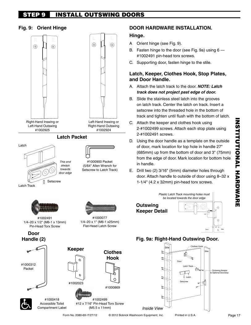
door hardWare insTallaTion.
hinge.
A Orient hinge (see Fig. 9).
B. Fasten hinge to the door (see Fig. 9a) using 6 — #1002491 pin-head torx screws.
C. Supporting door, fasten hinge to the stile.
latch, keeper, clothes hook, stop plates, and door handle.A. Attach the latch track to the door. NOTE: Latch
track does not project past edge of door.
B. Slide the stainless steel latch into the grooves on latch track. Center the latch on track. Insert a setscrew into the threaded hole in the bottom of track and tighten until flush with the bottom of latch.
C. Attach the keeper and clothes hook using 2-#1002499 screws. Attach each stop plate using 2-#1002491 screws.
D. Using the door handle as a template on the outside of door, mark location for top hole in handle 27" (685mm) up from the bottom of door and 3" (75mm) from the edge of door. Mark location for bottom hole in handle.
E. Drill two (2) 3/16" (5mm) diameter holes through door. Attach handle to outside of door using 8 –32 x 1-1/4" (4.2 x 32mm) pin-head torx screws.
Inside View
Fig.9: OrientHinge
Latch Track
Latch
Left-Hand Inswing orRight-Hand Outswing
#1002924
Right-Hand Inswing or Left-Hand Outswing
#1002925
Setscrew
#1002499#12 x 7/16" Pin-Head Torx Screw
(M5.5 x 11mm)
This end always towards
door edge
outswingkeeper detail
Plastic Latch Track mounting holes must be located towards the door edge
#1000869
clotheshook
INS
TIT
UT
ION
AL
HA
RD
wA
RE
Form No. 2080-69 r/27/12 © 2012 Bobrick Washroom Equipment, Inc. Printed in U.S.A.
3/4'' Thick Stile
5/16'' Wide Flangefor 3/4'' Thick Stile
2. Close Shoe
Flat ShoeRetainer
Flat Washerat Floor
3. Secure Shoe in placeby installing#1002189
Shoe Retainer Screw
Anchor Bolt,Nuts & Washers
Shoe
1. Trap Bottom Flangeunder Flat Shoe Retainer
3/4'' Thick Stile
5/16'' Wide Flangefor 3/4'' Thick Stile
2. Close Shoe
Flat ShoeRetainer
Flat Washerat Floor
3. Secure Shoe in placeby installing#1002189
Shoe Retainer Screw
Anchor Bolt,Nuts & Washers
Shoe
1. Trap Bottom Flangeunder Flat Shoe Retainer
Page 18
A. Locate proper width shoe for stile.
B. Confirm shoe retainer (part number 1002186) is installed on anchor bolt next to flat washer closest to floor or ceiling. For anchor assembly detail, reference diagram on Page 4 of complete installation instruction sheet.
C. Shoes accommodate 1” thick or 3/4” thick stiles. For 3/4” thick stiles, orient shoe with 5/16” wide flange return against faces and edge of stile.
D(1). Standard Stile Installation - See Fig. 10a
Open end of shoe and slide onto bottom of stile, trapping bottom flange under shoe retainer.
Close open end of shoe, overlapping so holes are aligned. Install flat head retaining screw through double thickness of material to close shoe.
D(2). Stile-to-Wall Installation - See Fig. 10b
Stile-to-wall shoe retaining clip (part number 1002185) is supplied with every stile-to-wall. Locate shoe retaining clip.
Hold retaining clip by its extended leaf with pliers. Spread shoe open at least one inch and insert retaining clip into hole on inner leaf of shoe until it snaps into place.
Open end of shoe and slide onto bottom of stile, trapping bottom flange under shoe retainer. Shoe retaining clip will be positioned against wall.
Close edges of shoe together until remaining hole snaps into place on retaining clip.
E. Remove protective covering and wipe shoe clean.
INSTALL SHOESSTEp 10
Fig. 10a: standard stile installation. Fig. 10b: stile-to-Wall installation.
REpLACEmENT SHOE GUIDE
stile Width Bobrick part number 3" 1002175 4" 1002176 5" 1002184 6" 1002177 8" 1002178 10" 1002179 12" 1002180 16" 1002181 20" 1002182 24" 1002183
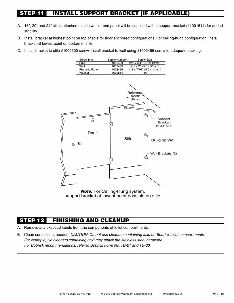
Form No. 2080-69 r7/27/12 © 2012 Bobrick Washroom Equipment, Inc. Printed in U.S.A.
SupportBracket
#1001514
Door
Stile
Wall Brackets (3)
Building Wall
Note: For Ceiling-Hung system,support bracket at lowest point possible on stile.
Reference8-5/8"(20mm)
A. Remove any exposed labels from the components of toilet compartments.
B. Clean surfaces as needed. CAUTION: Do not use cleaners containing acid on Bobrick toilet compartments. For example, tile cleaners containing acid may attack the stainless steel hardware. For Bobrick recommendations, refer to Bobrick Form No. TB-21 and TB-60.
FINISHING AND CLEANUpSTEp 12
INSTALL SUppORT BRACkET (IF AppLICABLE)STEp 11
A. 16", 20" and 24" stiles attached to side wall or end panel will be supplied with a support bracket (#1001514) for added stability.
B. Install bracket at highest point on top of stile for floor anchored configurations. For ceiling-hung configuration, install bracket at lowest point on bottom of stile.
C. Install bracket to stile #1002500 screw. Install bracket to wall using #1002495 screw to adequate backing.
Screw Into Screw Number Screw SizeStile 1002499 #12 x 3/4" (5.5 x 19mm)Wall 1002495 #12 x 2" (5.5 x 50mm)Phenolic Panel 1002499 #12 x 7/16" (5.5 x 11mm)Washer 1000814 NA
PAGE 19
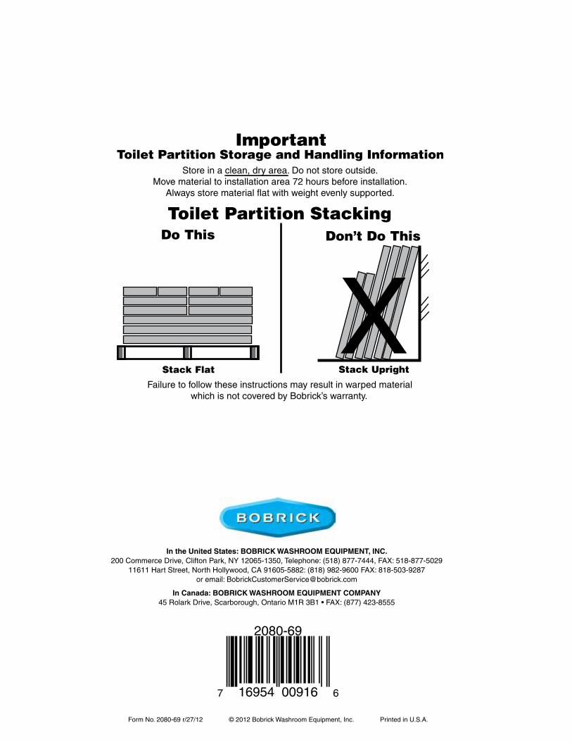
Form No. 2080-69 r/27/12 © 2012 Bobrick Washroom Equipment, Inc. Printed in U.S.A.Page 20
in the united states: BoBrick Washroom eQuipmenT, inc.200 Commerce Drive, Clifton Park, NY 12065-1350, Telephone: (518) 877-7444, FAX: 518-877-5029
11611 Hart Street, North Hollywood, CA 91605-5882: (818) 982-9600 FAX: 818-503-9287or email: [email protected]
in canada: BoBrick Washroom eQuipmenT company45RolarkDrive,Scarborough,OntarioM1R3B1•FAX:(877)423-8555
7 16954 00916 6
2080-69