Embed Size (px)
Citation preview
09/11 506635−01
�������� ���������Page 1
�2011 Lennox Industries Inc.Dallas, Texas, USA
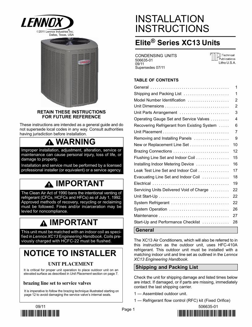
RETAIN THESE INSTRUCTIONSFOR FUTURE REFERENCE
These instructions are intended as a general guide and donot supersede local codes in any way. Consult authoritieshaving jurisdiction before installation.
WARNINGImproper installation, adjustment, alteration, service ormaintenance can cause personal injury, loss of life, ordamage to property.
Installation and service must be performed by a licensedprofessional installer (or equivalent) or a service agency.
IMPORTANTThe Clean Air Act of 1990 bans the intentional venting ofrefrigerant (CFCs, HCFCs and HFCs) as of July 1, 1992.Approved methods of recovery, recycling or reclaimingmust be followed. Fines and/or incarceration may belevied for noncompliance.
IMPORTANTThis unit must be matched with an indoor coil as speci-fied in Lennox XC13 Engineering Handbook. Coils pre-viously charged with HCFC−22 must be flushed.
NOTICE TO INSTALLERUNIT PLACEMENT
It is critical for proper unit operation to place outdoor unit on anelevated surface as described in Unit Placement section on page 7.
brazing line set to service valves
It is imperative to follow the brazing technique illustrated starting onpage 12 to avoid damaging the service valve’s internal seals.
INSTALLATIONINSTRUCTIONS
Elite® Series XC13 Units
CONDENSING UNITS506635−01 09/11Supersedes 07/11
TABLE OF CONTENTS
General 1. . . . . . . . . . . . . . . . . . . . . . . . . . . . . . . . . . . . . .
Shipping and Packing List 1. . . . . . . . . . . . . . . . . . . . . .
Model Number Identification 2. . . . . . . . . . . . . . . . . . . .
Unit Dimensions 2. . . . . . . . . . . . . . . . . . . . . . . . . . . . . . .
Unit Parts Arrangement 3. . . . . . . . . . . . . . . . . . . . . . . .
Operating Gauge Set and Service Valves 4. . . . . . . . .
Recovering Refrigerant from Existing System 6. . . . .
Unit Placement 7. . . . . . . . . . . . . . . . . . . . . . . . . . . . . . . .
Removing and Installing Panels 9. . . . . . . . . . . . . . . . .
New or Replacement Line Set 10. . . . . . . . . . . . . . . . . . .
Brazing Connections 12. . . . . . . . . . . . . . . . . . . . . . . . . . .
Flushing Line Set and Indoor Coil 15. . . . . . . . . . . . . . . .
Installing Indoor Metering Device 16. . . . . . . . . . . . . . . .
Leak Test Line Set and Indoor Coil 17. . . . . . . . . . . . . . .
Evacuating Line Set and Indoor Coil 18. . . . . . . . . . . . .
Electrical 19. . . . . . . . . . . . . . . . . . . . . . . . . . . . . . . . . . . . .
Servicing Units Delivered Void of Charge 22. . . . . . . . .
Unit Start−Up 22. . . . . . . . . . . . . . . . . . . . . . . . . . . . . . . . . .
System Refrigerant 22. . . . . . . . . . . . . . . . . . . . . . . . . . . .
System Operation 26. . . . . . . . . . . . . . . . . . . . . . . . . . . . .
Maintenance 27. . . . . . . . . . . . . . . . . . . . . . . . . . . . . . . . . .
Start−Up and Performance Checklist 28. . . . . . . . . . . . .
General
The XC13 Air Conditioners, which will also be referred to inthis instruction as the outdoor unit, uses HFC−410A
refrigerant. This outdoor unit must be installed with amatching indoor unit and line set as outlined in the LennoxXC13 Engineering Handbook.
Shipping and Packing List
Check the unit for shipping damage and listed times beloware intact. If damaged, or if parts are missing, immediatelycontact the last shipping carrier.
1 � Assembled outdoor unit.
1 � Refrigerant flow control (RFC) kit (Fixed Orifice)
Litho U.S.A.
Page 2
506635−01 11/10
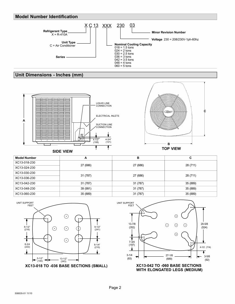
Model Number Identification
C 13 XXX
Unit TypeC = Air Conditioner
Series
Nominal Cooling Capacity018 = 1.5 tons024 = 2 tons 030 = 2.5 tons036 = 3 tons 042 = 3.5 tons048 = 4 tons 060 = 5 tons
Minor Revision Number
230
Voltage 230 = 208/230V−1ph−60hz
Refrigerant TypeX = R−410A
X 03
Unit Dimensions − Inches (mm)
ELECTRICAL INLETS
SIDE VIEW
SUCTION LINECONNECTION
LIQUID LINECONNECTION
4−1/2"(108)
4−3/4"(121)
TOP VIEW
A
B
C
Model Number A B C
XC13−018−23027 (686) 27 (686) 28 (711)
XC13−024−230
XC13−030−23031 (787) 27 (686) 28 (711)
XC13−036−230
XC13−042−230 31 (787) 31 (787) 35 (889)
XC13−048−230 39 (991) 31 (787) 35 (889)
XC13−060−230 35 (889) 31 (787) 35 (889)
UNIT SUPPORTFEET
8−1/2"(216)
8−3/4(222)
5−1/2"(140)
9−1/2"(241)
8−1/4"(210)
13−1/2"(343)
XC13−018 TO −036 BASE SECTIONS (SMALL)
3−1/4
(83)
UNIT SUPPORTFEET
XC13−042 TO −060 BASE SECTIONS WITH ELONGATED LEGS (MEDIUM)
13−7/8
(352)
7−3/4(197)
27−1/8
(689)3−5/8
(92)
4−1/2 (114)
20−5/8
(524)
Page 3
XC13 SERIES
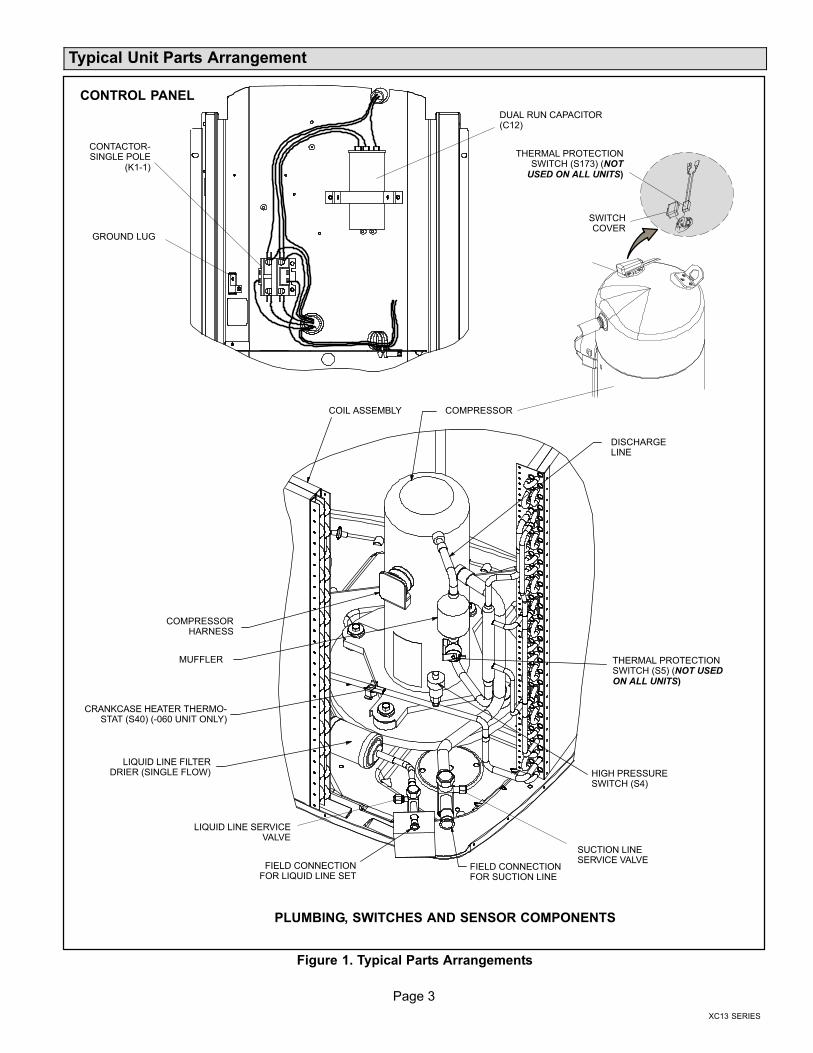
Typical Unit Parts Arrangement
LIQUID LINE FILTERDRIER (SINGLE FLOW)
FIELD CONNECTIONFOR LIQUID LINE SET
LIQUID LINE SERVICEVALVE
SUCTION LINESERVICE VALVE
FIELD CONNECTIONFOR SUCTION LINE
MUFFLER
HIGH PRESSURESWITCH (S4)
COMPRESSORHARNESS
GROUND LUG
CONTACTOR−SINGLE POLE
(K1−1)
DUAL RUN CAPACITOR(C12)
CONTROL PANEL
PLUMBING, SWITCHES AND SENSOR COMPONENTS
COMPRESSOR
DISCHARGELINE
COIL ASSEMBLY
CRANKCASE HEATER THERMO-STAT (S40) (−060 UNIT ONLY)
SWITCHCOVER
THERMAL PROTECTIONSWITCH (S173) (NOT
USED ON ALL UNITS)
THERMAL PROTECTIONSWITCH (S5) (NOT USEDON ALL UNITS)
Figure 1. Typical Parts Arrangements
Page 4
506635−01 11/10
WARNINGElectric Shock Hazard. Can cause injuryor death. Unit must be grounded inaccordance with national and localcodes.
Line voltage is present at all componentswhen unit is not in operation on units withsingle-pole contactors. Disconnect allremote electric power supplies beforeopening access panel. Unit may havemultiple power supplies.
CAUTIONPhysical contact with metal edges and corners whileapplying excessive force or rapid motion can result inpersonal injury. Be aware of, and use caution whenworking near these areas during installation or whileservicing this equipment.
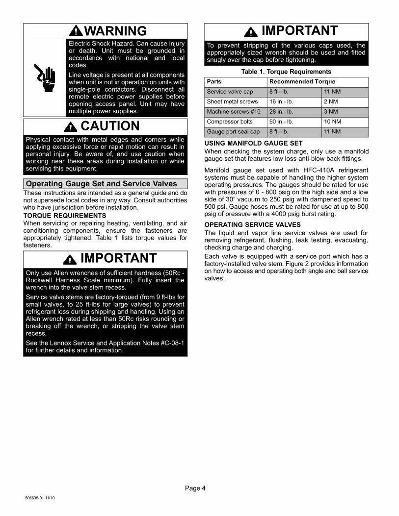
Operating Gauge Set and Service ValvesThese instructions are intended as a general guide and donot supersede local codes in any way. Consult authoritieswho have jurisdiction before installation.
TORQUE REQUIREMENTSWhen servicing or repairing heating, ventilating, and airconditioning components, ensure the fasteners areappropriately tightened. Table 1 lists torque values forfasteners.
IMPORTANTOnly use Allen wrenches of sufficient hardness (50Rc −Rockwell Harness Scale minimum). Fully insert thewrench into the valve stem recess.
Service valve stems are factory−torqued (from 9 ft−lbs forsmall valves, to 25 ft−lbs for large valves) to preventrefrigerant loss during shipping and handling. Using anAllen wrench rated at less than 50Rc risks rounding orbreaking off the wrench, or stripping the valve stemrecess.
See the Lennox Service and Application Notes #C−08−1for further details and information.
IMPORTANTTo prevent stripping of the various caps used, theappropriately sized wrench should be used and fittedsnugly over the cap before tightening.
Table 1. Torque Requirements
Parts Recommended Torque
Service valve cap 8 ft.− lb. 11 NM
Sheet metal screws 16 in.− lb. 2 NM
Machine screws #10 28 in.− lb. 3 NM
Compressor bolts 90 in.− lb. 10 NM
Gauge port seal cap 8 ft.− lb. 11 NM
USING MANIFOLD GAUGE SET
When checking the system charge, only use a manifoldgauge set that features low loss anti−blow back fittings.
Manifold gauge set used with HFC−410A refrigerantsystems must be capable of handling the higher systemoperating pressures. The gauges should be rated for usewith pressures of 0 − 800 psig on the high side and a lowside of 30" vacuum to 250 psig with dampened speed to500 psi. Gauge hoses must be rated for use at up to 800psig of pressure with a 4000 psig burst rating.
OPERATING SERVICE VALVES
The liquid and vapor line service valves are used forremoving refrigerant, flushing, leak testing, evacuating,checking charge and charging.
Each valve is equipped with a service port which has afactory−installed valve stem. Figure 2 provides informationon how to access and operating both angle and ball servicevalves.
Page 5
XC13 SERIES
(VALVE STEM SHOWNCLOSED) INSERT HEXWRENCH HERE
SERVICE PORT CORE
SERVICE PORT CAP
ANGLE−TYPE SERVICE VALVE(FRONT−SEATED CLOSED)
SERVICE PORTCORE
TO OUTDOOR UNIT
STEM CAP
(VALVE STEM SHOWN OPEN)INSERT HEX WRENCH HERE
TO INDOORUNIT
ANGLE−TYPE SERVICE VALVE(BACK−SEATED OPENED)
BALL (SHOWNCLOSED)
SERVICE PORTCORE
TO INDOOR UNIT
TO OUTDOORUNIT
TO OPEN ROTATE STEMCOUNTERCLOCKWISE 90°.
TO CLOSE ROTATE STEMCLOCKWISE 90°.
SERVICE PORT
SERVICE PORTCAP
STEM CAP
VALVESTEM
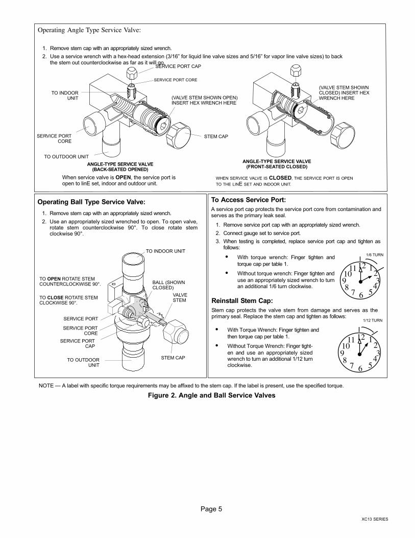
Operating Angle Type Service Valve:
1. Remove stem cap with an appropriately sized wrench.
2. Use a service wrench with a hex−head extension (3/16" for liquid line valve sizes and 5/16" for vapor line valve sizes) to backthe stem out counterclockwise as far as it will go.
Operating Ball Type Service Valve:
1. Remove stem cap with an appropriately sized wrench.
2. Use an appropriately sized wrenched to open. To open valve,rotate stem counterclockwise 90°. To close rotate stemclockwise 90°.
123
4567
8910
11 12
1/12 TURN
To Access Service Port:
A service port cap protects the service port core from contamination andserves as the primary leak seal.
1. Remove service port cap with an appropriately sized wrench.
2. Connect gauge set to service port.
3. When testing is completed, replace service port cap and tighten asfollows:
� With torque wrench: Finger tighten and
torque cap per table 1.
� Without torque wrench: Finger tighten and
use an appropriately sized wrench to turnan additional 1/6 turn clockwise.
123
4567
8910
11 12
1/6 TURN
WHEN SERVICE VALVE IS CLOSED, THE SERVICE PORT IS OPEN
TO THE LINE SET AND INDOOR UNIT.
When service valve is OPEN, the service port isopen to linE set, indoor and outdoor unit.
Reinstall Stem Cap:
Stem cap protects the valve stem from damage and serves as theprimary seal. Replace the stem cap and tighten as follows:
� With Torque Wrench: Finger tighten and
then torque cap per table 1.
� Without Torque Wrench: Finger tight-
en and use an appropriately sizedwrench to turn an additional 1/12 turnclockwise.
NOTE � A label with specific torque requirements may be affixed to the stem cap. If the label is present, use the specified torque.
Figure 2. Angle and Ball Service Valves
Page 6
506635−01 11/10
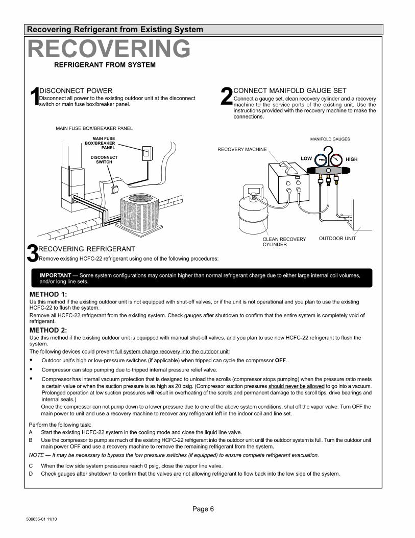
Recovering Refrigerant from Existing System
MAIN FUSE BOX/BREAKER PANEL
Disconnect all power to the existing outdoor unit at the disconnectswitch or main fuse box/breaker panel.
DISCONNECT POWER CONNECT MANIFOLD GAUGE SET
MANIFOLD GAUGES
RECOVERY MACHINE
CLEAN RECOVERYCYLINDER
OUTDOOR UNIT
HIGHLOW
Connect a gauge set, clean recovery cylinder and a recoverymachine to the service ports of the existing unit. Use theinstructions provided with the recovery machine to make theconnections.
METHOD 1:Us this method if the existing outdoor unit is not equipped with shut−off valves, or if the unit is not operational and you plan to use the existingHCFC−22 to flush the system.
Remove all HCFC−22 refrigerant from the existing system. Check gauges after shutdown to confirm that the entire system is completely void ofrefrigerant.
METHOD 2:Use this method if the existing outdoor unit is equipped with manual shut−off valves, and you plan to use new HCFC−22 refrigerant to flush thesystem.
The following devices could prevent full system charge recovery into the outdoor unit:
� Outdoor unit’s high or low−pressure switches (if applicable) when tripped can cycle the compressor OFF.
� Compressor can stop pumping due to tripped internal pressure relief valve.
� Compressor has internal vacuum protection that is designed to unload the scrolls (compressor stops pumping) when the pressure ratio meets
a certain value or when the suction pressure is as high as 20 psig. (Compressor suction pressures should never be allowed to go into a vacuum.
Prolonged operation at low suction pressures will result in overheating of the scrolls and permanent damage to the scroll tips, drive bearings and
internal seals.)
Once the compressor can not pump down to a lower pressure due to one of the above system conditions, shut off the vapor valve. Turn OFF the
main power to unit and use a recovery machine to recover any refrigerant left in the indoor coil and line set.
Perform the following task:
A Start the existing HCFC−22 system in the cooling mode and close the liquid line valve.
B Use the compressor to pump as much of the existing HCFC−22 refrigerant into the outdoor unit until the outdoor system is full. Turn the outdoor unitmain power OFF and use a recovery machine to remove the remaining refrigerant from the system.
NOTE � It may be necessary to bypass the low pressure switches (if equipped) to ensure complete refrigerant evacuation.
C When the low side system pressures reach 0 psig, close the vapor line valve.
D Check gauges after shutdown to confirm that the valves are not allowing refrigerant to flow back into the low side of the system.
RECOVERINGREFRIGERANT FROM SYSTEM
Remove existing HCFC−22 refrigerant using one of the following procedures:
RECOVERING REFRIGERANT
IMPORTANT � Some system configurations may contain higher than normal refrigerant charge due to either large internal coil volumes,and/or long line sets.
1 2
3
DISCONNECTSWITCH
MAIN FUSEBOX/BREAKER
PANEL
Page 7
XC13 SERIES
CONTROL PANELACCESS
LOCATION
6 (152)
36 (914)
12 (305)30 (762)
LINE SETCONNECTIONS
24 (610)
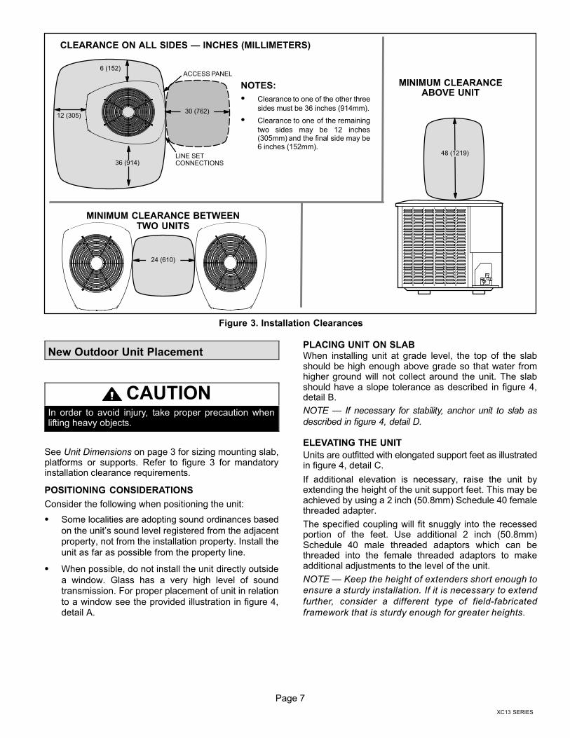
48 (1219)
MINIMUM CLEARANCE BETWEENTWO UNITS
CLEARANCE ON ALL SIDES � INCHES (MILLIMETERS)
ACCESS PANEL
MINIMUM CLEARANCEABOVE UNIT
NOTES:
� Clearance to one of the other three
sides must be 36 inches (914mm).
� Clearance to one of the remaining
two sides may be 12 inches(305mm) and the final side may be6 inches (152mm).
Figure 3. Installation Clearances
New Outdoor Unit Placement
CAUTIONIn order to avoid injury, take proper precaution whenlifting heavy objects.
See Unit Dimensions on page 3 for sizing mounting slab,platforms or supports. Refer to figure 3 for mandatoryinstallation clearance requirements.
POSITIONING CONSIDERATIONS
Consider the following when positioning the unit:
� Some localities are adopting sound ordinances based
on the unit’s sound level registered from the adjacentproperty, not from the installation property. Install the
unit as far as possible from the property line.
� When possible, do not install the unit directly outside
a window. Glass has a very high level of soundtransmission. For proper placement of unit in relation
to a window see the provided illustration in figure 4,detail A.
PLACING UNIT ON SLAB
When installing unit at grade level, the top of the slabshould be high enough above grade so that water fromhigher ground will not collect around the unit. The slabshould have a slope tolerance as described in figure 4,detail B.
NOTE � If necessary for stability, anchor unit to slab as
described in figure 4, detail D.
ELEVATING THE UNIT
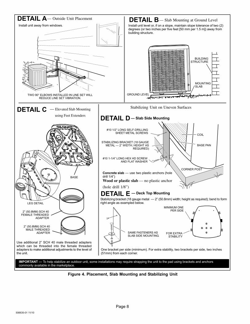
Units are outfitted with elongated support feet as illustratedin figure 4, detail C.
If additional elevation is necessary, raise the unit byextending the height of the unit support feet. This may beachieved by using a 2 inch (50.8mm) Schedule 40 femalethreaded adapter.
The specified coupling will fit snuggly into the recessedportion of the feet. Use additional 2 inch (50.8mm)Schedule 40 male threaded adaptors which can bethreaded into the female threaded adaptors to makeadditional adjustments to the level of the unit.
NOTE � Keep the height of extenders short enough to
ensure a sturdy installation. If it is necessary to extend
further, consider a different type of field−fabricated
framework that is sturdy enough for greater heights.
Page 8
506635−01 11/10
LEG DETAIL
BASE
2" (50.8MM) SCH 40FEMALE THREADED
ADAPTER
Concrete slab � use two plastic anchors (holedrill 1/4")
Wood or plastic slab — no plastic anchor
(hole drill 1/8”)
COIL
BASE PAN
CORNER POST
STABILIZING BRACKET (18 GAUGEMETAL � 2" WIDTH; HEIGHT AS
REQUIRED)
� Slab Side Mounting
#10 1/2" LONG SELF−DRILLINGSHEET METAL SCREWS
#10 1−1/4" LONG HEX HD SCREWAND FLAT WASHER
MINIMUM ONEPER SIDE
Stabilizing bracket (18 gauge metal � 2" (50.8mm) width; height as required); bend to formright angle as exampled below.
FOR EXTRASTABILITY
� Deck Top Mounting
— Elevated Slab Mounting
using Feet Extenders
Stabilizing Unit on Uneven Surfaces
Install unit level or, if on a slope, maintain slope tolerance of two (2)degrees (or two inches per five feet [50 mm per 1.5 m]) away frombuilding structure.
MOUNTINGSLAB
BUILDINGSTRUCTURE
GROUND LEVEL
— Outside Unit Placement — Slab Mounting at Ground Level
SAME FASTENERS ASSLAB SIDE MOUNTING.
IMPORTANT � To help stabilize an outdoor unit, some installations may require strapping the unit to the pad using brackets and anchorscommonly available in the marketplace.
DETAIL A DETAIL B
DETAIL C
DETAIL D
2" (50.8MM) SCH 40MALE THREADED
ADAPTER
Use additional 2" SCH 40 male threaded adapterswhich can be threaded into the female threadedadapters to make additional adjustments to the level ofthe unit.
TWO 90° ELBOWS INSTALLED IN LINE SET WILLREDUCE LINE SET VIBRATION.
Install unit away from windows.
One bracket per side (minimum). For extra stability, two brackets per side, two inches(51mm) from each corner.
DETAIL E
Figure 4. Placement, Slab Mounting and Stabilizing Unit

Page 9
XC13 SERIES
ROOF MOUNTING
Install the unit a minimum of 6 inches (152 mm) above theroof surface to avoid ice build−up around the unit. Locatethe unit above a load bearing wall or area of the roof thatcan adequately support the unit. Consult local codes forrooftop applications.
NOTICERoof Damage!
This system contains both refrigerant and oil. Somerubber roofing material may absorb oil and cause therubber to swell when it comes into contact with oil. Therubber will then bubble and could cause leaks. Protectthe roof surface to avoid exposure to refrigerant and oilduring service and installation. Failure to follow thisnotice could result in damage to roof surface.
Removing and Installing Panels
IMPORTANTDo not allow panels to hang on unit by top tab. Tab is foralignment and not designed to support weight of panel.
WARNINGTo prevent personal injury, or damage to panels, unit orstructure, be sure to observe the following:
While installing or servicing this unit, carefully stow allremoved panels out of the way, so that the panels will notcause injury to personnel, nor cause damage to objectsor structures nearby, nor will the panels be subjected todamage (e.g., being bent or scratched).
While handling or stowing the panels, consider anyweather conditions, especially windy conditions, thatmay cause panels to be blown around and battered.
LOUVERED PANEL REMOVALRemove the louvered panels as follows:
1. Remove two screws, allowing the panel to swing open slightly.
2. Hold the panel firmly throughout this procedure. Rotate bottom corner ofpanel away from hinged corner post until lower three tabs clear the slots asillustrated in detail B.
3. Move panel down until lip of upper tab clears the top slot in corner post asillustrated in detail A.
LOUVERED PANEL INSTALLATION
Position the panel almost parallel with the unit as illustrated in detail D with the
screw side as close to the unit as possible. Then, in a continuous motion:
1. Slightly rotate and guide the lip of top tab inward as illustrated in detail A andC; then upward into the top slot of the hinge corner post.
2. Rotate panel to vertical to fully engage all tabs.
3. Holding the panel’s hinged side firmly in place, close the right−hand side ofthe panel, aligning the screw holes.
4. When panel is correctly positioned and aligned, insert the screws andtighten.
DETAIL A
DETAIL B
ROTATE IN THIS DIRECTION;THEN DOWN TO REMOVE
PANEL
SCREWHOLES
LIP
IMPORTANT! DO NOT ALLOW PANELS TO HANG ON UNIT BY TOP TAB. TAB IS FORALIGNMENT AND NOT DESIGNED TO SUPPORT WEIGHT OF PANEL.
PANEL SHOWN SLIGHTLY ROTATED TO ALLOW TOP TAB TO EXIT (ORENTER) TOP SLOT FOR REMOVING (OR INSTALLING) PANEL.
MAINTAIN MINIMUM PANEL ANGLE (AS CLOSE TO PARALLELWITH THE UNIT AS POSSIBLE) WHILE INSTALLING PANEL.
PREFERRED ANGLEFOR INSTALLATION
ANGLE MAY BE TOOEXTREME
HOLD DOOR FIRMLY TO THE HINGED SIDE TO MAINTAIN
FULLY−ENGAGED TABS
Detail C
Figure 5. Removing and Installing Panels
Page 10
506635−01 11/10
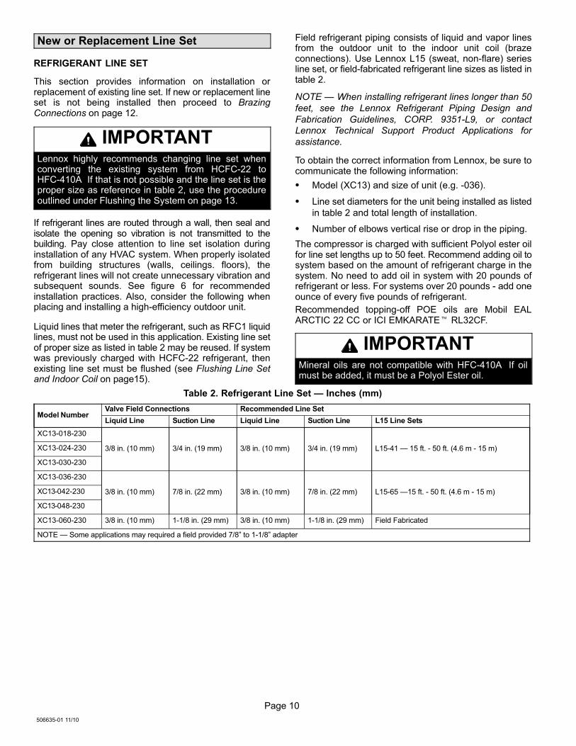
New or Replacement Line Set
REFRIGERANT LINE SET
This section provides information on installation orreplacement of existing line set. If new or replacement lineset is not being installed then proceed to BrazingConnections on page 12.
IMPORTANTLennox highly recommends changing line set whenconverting the existing system from HCFC−22 toHFC−410A. If that is not possible and the line set is theproper size as reference in table 2, use the procedureoutlined under Flushing the System on page 13.
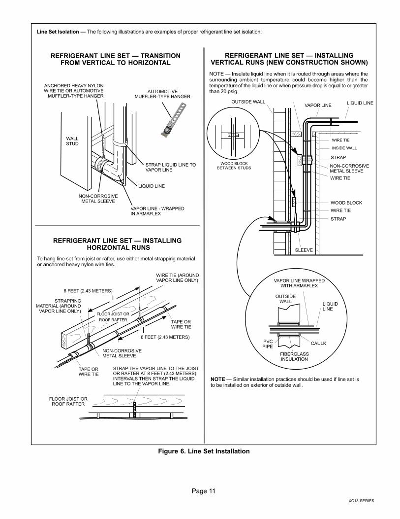
If refrigerant lines are routed through a wall, then seal andisolate the opening so vibration is not transmitted to thebuilding. Pay close attention to line set isolation duringinstallation of any HVAC system. When properly isolatedfrom building structures (walls, ceilings. floors), therefrigerant lines will not create unnecessary vibration andsubsequent sounds. See figure 6 for recommendedinstallation practices. Also, consider the following whenplacing and installing a high−efficiency outdoor unit.
Liquid lines that meter the refrigerant, such as RFC1 liquidlines, must not be used in this application. Existing line setof proper size as listed in table 2 may be reused. If systemwas previously charged with HCFC−22 refrigerant, thenexisting line set must be flushed (see Flushing Line Setand Indoor Coil on page15).
Field refrigerant piping consists of liquid and vapor linesfrom the outdoor unit to the indoor unit coil (brazeconnections). Use Lennox L15 (sweat, non−flare) seriesline set, or field−fabricated refrigerant line sizes as listed intable 2.
NOTE � When installing refrigerant lines longer than 50
feet, see the Lennox Refrigerant Piping Design and
Fabrication Guidelines, CORP. 9351−L9, or contact
Lennox Technical Support Product Applications for
assistance.
To obtain the correct information from Lennox, be sure tocommunicate the following information:
� Model (XC13) and size of unit (e.g. −036).
� Line set diameters for the unit being installed as listed
in table 2 and total length of installation.
� Number of elbows vertical rise or drop in the piping.
The compressor is charged with sufficient Polyol ester oilfor line set lengths up to 50 feet. Recommend adding oil tosystem based on the amount of refrigerant charge in thesystem. No need to add oil in system with 20 pounds ofrefrigerant or less. For systems over 20 pounds − add oneounce of every five pounds of refrigerant.
Recommended topping−off POE oils are Mobil EALARCTIC 22 CC or ICI EMKARATE� RL32CF.
IMPORTANTMineral oils are not compatible with HFC−410A. If oilmust be added, it must be a Polyol Ester oil.
Table 2. Refrigerant Line Set � Inches (mm)
Model NumberValve Field Connections Recommended Line Set
Liquid Line Suction Line Liquid Line Suction Line L15 Line Sets
XC13−018−230
3/8 in. (10 mm) 3/4 in. (19 mm) 3/8 in. (10 mm) 3/4 in. (19 mm) L15−41 � 15 ft. − 50 ft. (4.6 m − 15 m)XC13−024−230
XC13−030−230
XC13−036−230
3/8 in. (10 mm) 7/8 in. (22 mm) 3/8 in. (10 mm) 7/8 in. (22 mm) L15−65 �15 ft. − 50 ft. (4.6 m − 15 m)XC13−042−230
XC13−048−230
XC13−060−230 3/8 in. (10 mm) 1−1/8 in. (29 mm) 3/8 in. (10 mm) 1−1/8 in. (29 mm) Field Fabricated
NOTE � Some applications may required a field provided 7/8" to 1−1/8" adapter
Page 11
XC13 SERIES
ANCHORED HEAVY NYLONWIRE TIE OR AUTOMOTIVE
MUFFLER-TYPE HANGER
STRAP LIQUID LINE TOVAPOR LINE
WALLSTUD
LIQUID LINE
NON−CORROSIVEMETAL SLEEVE
VAPOR LINE − WRAPPEDIN ARMAFLEX
AUTOMOTIVEMUFFLER-TYPE HANGER
REFRIGERANT LINE SET � TRANSITIONFROM VERTICAL TO HORIZONTAL
Line Set Isolation � The following illustrations are examples of proper refrigerant line set isolation:
STRAPPINGMATERIAL (AROUND
VAPOR LINE ONLY)
TAPE ORWIRE TIE
WIRE TIE (AROUNDVAPOR LINE ONLY)
FLOOR JOIST ORROOF RAFTER
TAPE ORWIRE TIE
To hang line set from joist or rafter, use either metal strapping materialor anchored heavy nylon wire ties.
8 FEET (2.43 METERS)
STRAP THE VAPOR LINE TO THE JOISTOR RAFTER AT 8 FEET (2.43 METERS)INTERVALS THEN STRAP THE LIQUIDLINE TO THE VAPOR LINE.
FLOOR JOIST OR
ROOF RAFTER
REFRIGERANT LINE SET � INSTALLING HORIZONTAL RUNS
NOTE � Similar installation practices should be used if line set isto be installed on exterior of outside wall.
PVCPIPE
FIBERGLASSINSULATION
CAULK
OUTSIDEWALL
VAPOR LINE WRAPPEDWITH ARMAFLEX
LIQUIDLINE
OUTSIDE WALL LIQUID LINEVAPOR LINE
WOOD BLOCKBETWEEN STUDS
STRAP
WOOD BLOCK
STRAP
SLEEVE
WIRE TIE
WIRE TIE
WIRE TIE
INSIDE WALL
REFRIGERANT LINE SET � INSTALLINGVERTICAL RUNS (NEW CONSTRUCTION SHOWN)
NOTE � Insulate liquid line when it is routed through areas where thesurrounding ambient temperature could become higher than thetemperature of the liquid line or when pressure drop is equal to or greaterthan 20 psig.
NON−CORROSIVEMETAL SLEEVE
NON−CORROSIVEMETAL SLEEVE
8 FEET (2.43 METERS)
Figure 6. Line Set Installation

Page 12
506635−01 11/10
Brazing Connections
Use the procedures outline in figures 7 and 8 for brazingline set connections to service valves.
WARNINGPolyol Ester (POE) oils used with HFC−410Arefrigerant absorb moisture very quickly. It is veryimportant that the refrigerant system be kept closedas much as possible. DO NOT remove line set capsor service valve stub caps until you are ready to makeconnections.
WARNINGDanger of fire. Bleeding the refrigerantcharge from only the high side may resultin pressurization of the low side shell andsuction tubing. Application of a brazingtorch to a pressurized system may resultin ignition of the refrigerant and oilmixture − Check the high and lowpressures before applying heat.
WARNINGWhen using a high pressure gas such asdry nitrogen to pressurize a refrigerationor air conditioning system, use aregulator that can control the pressuredown to 1 or 2 psig (6.9 to 13.8 kPa).
CAUTIONBrazing alloys and flux contain materials which arehazardous to your health.
Avoid breathing vapors or fumes from brazingoperations. Perform operations only in well−ventilatedareas.
Wear gloves and protective goggles or face shield toprotect against burns.
Wash hands with soap and water after handling brazingalloys and flux.
IMPORTANTConnect gauge set low pressure side to vapor lineservice valve and repeat procedure starting atparagraph 4 for brazing the liquid line to service portvalve.
IMPORTANTAllow braze joint to cool before removing the wet ragfrom the service valve. Temperatures above 250ºF candamage valve seals.
IMPORTANTUse silver alloy brazing rods with 5% minimum silveralloy for copper−to−copper brazing. Use 45% minimumalloy for copper−to−brass and copper−to−steel brazing.
WARNINGFire, Explosion and Personal SafetyHazard.
Failure to follow this warning couldresult in damage, personal injury ordeath.
Never use oxygen to pressurize orpurge refrigeration lines. Oxygen,when exposed to a spark or openflame, can cause fire and/or an ex-plosion, that could result in propertydamage, personal injury or death.

Page 13
XC13 SERIES
ATTACH THE MANIFOLD GAUGE SET FOR BRAZING LIQUID AND SUCTION / VAPOR LINE SERVICEVALVES
OUTDOORUNIT
LIQUID LINE
VAPOR LINE
LIQUID LINE SERVICEVALVE
SUCTION /VAPOR LINE
SERVICEVALVE
ATTACHGAUGES
INDOORUNIT
SUCTION / VAPOR SERVICE PORT MUST BEOPEN TO ALLOW EXIT POINT FOR NITROGEN
A Connect gauge set low pressure side toliquid line service valve (service port).
B Connect gauge set center port to bottle ofnitrogen with regulator.
C Remove core from valve in suction / vaporline service port to allow nitrogen to escape.
NITROGEN
HIGHLOWUSE REGULATOR TO FLOWNITROGEN AT 1 TO 2 PSIG.
B
A
C
WHEN BRAZING LINE SET TOSERVICE VALVES, POINT FLAME
AWAY FROM SERVICE VALVE.
Flow regulated nitrogen (at 1 to 2 psig) through the low−side refrigeration gauge set into the liquid line service port valve, and out of the suction /vapor line service port valve.
CUT AND DEBUR CAP AND CORE REMOVAL
Cut ends of the refrigerant lines square (free from nicks or dents)and debur the ends. The pipe must remain round. Do not crimp endof the line.
Remove service cap and core fromboth the suction / vapor and liquid lineservice ports.
1 2
LIQUID LINE SERVICEVALVE
SERVICEPORTCORE
SERVICE PORTCAP
SERVICEPORTCORE
SERVICEPORT CAP
CUT AND DEBUR
LINE SET SIZE MATCHESSERVICE VALVE CONNECTION
COPPER TUBESTUB
SERVICE VALVECONNECTION
REFRIGERANT LINE
DO NOT CRIMP SERVICE VALVECONNECTOR WHEN PIPE IS
SMALLER THAN CONNECTION
REDUCER
3
SUCTION / VAPOR LINESERVICE VALVE
LINE SET SIZE IS SMALLERTHAN CONNECTION
Figure 7. Brazing Procedures
Page 14
506635−01 11/10
WHEN BRAZING LINE SET TOSERVICE VALVES, POINT FLAME
AWAY FROM SERVICE VALVE.
LIQUID LINE SERVICE VALVE
LIQUID LINE
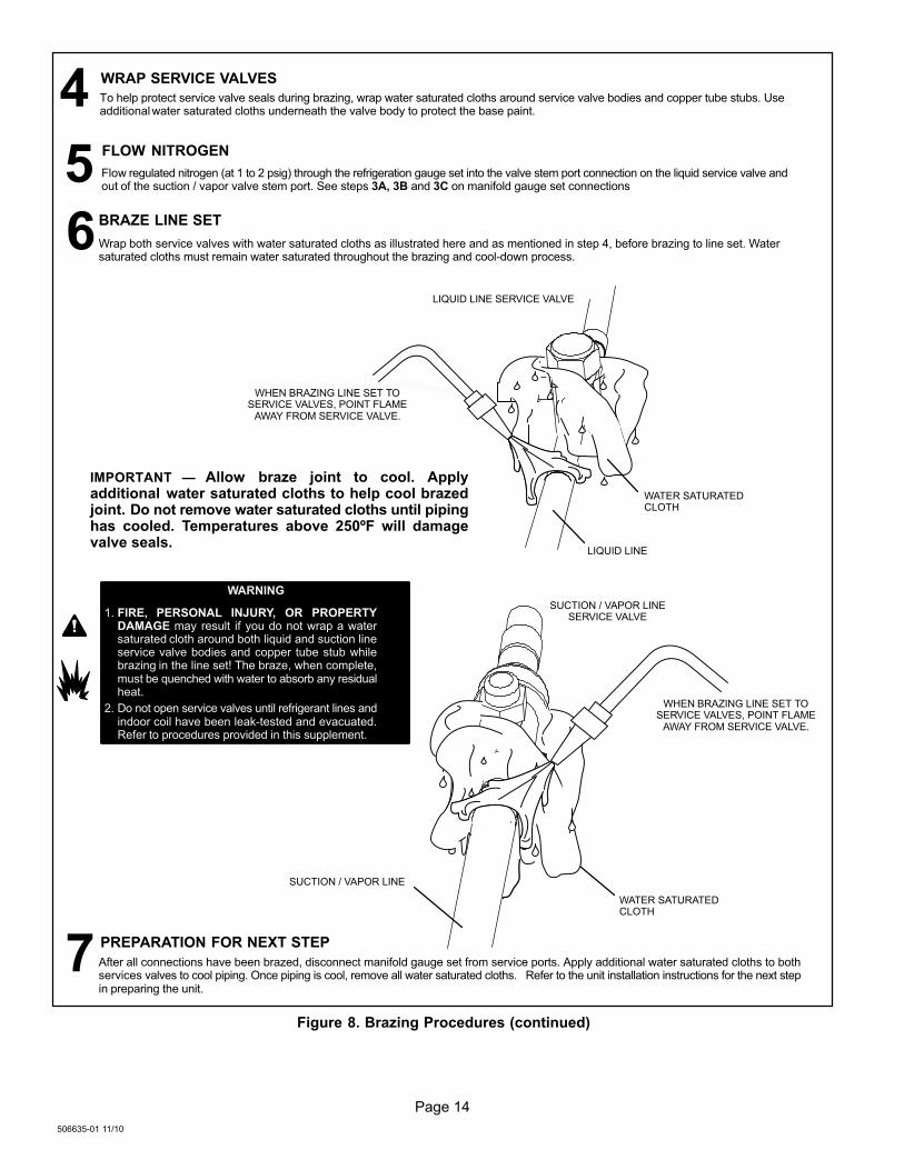
BRAZE LINE SET
Wrap both service valves with water saturated cloths as illustrated here and as mentioned in step 4, before brazing to line set. Watersaturated cloths must remain water saturated throughout the brazing and cool−down process.
WATER SATURATEDCLOTH
IMPORTANT � Allow braze joint to cool. Applyadditional water saturated cloths to help cool brazedjoint. Do not remove water saturated cloths until pipinghas cooled. Temperatures above 250ºF will damagevalve seals.
6
SUCTION / VAPOR LINE
WATER SATURATEDCLOTH
SUCTION / VAPOR LINESERVICE VALVE
After all connections have been brazed, disconnect manifold gauge set from service ports. Apply additional water saturated cloths to bothservices valves to cool piping. Once piping is cool, remove all water saturated cloths. Refer to the unit installation instructions for the next stepin preparing the unit.
WHEN BRAZING LINE SET TOSERVICE VALVES, POINT FLAME
AWAY FROM SERVICE VALVE.
PREPARATION FOR NEXT STEP7
WARNING
1. FIRE, PERSONAL INJURY, OR PROPERTYDAMAGE may result if you do not wrap a watersaturated cloth around both liquid and suction lineservice valve bodies and copper tube stub whilebrazing in the line set! The braze, when complete,must be quenched with water to absorb any residualheat.
2. Do not open service valves until refrigerant lines andindoor coil have been leak−tested and evacuated.Refer to procedures provided in this supplement.
WRAP SERVICE VALVES
To help protect service valve seals during brazing, wrap water saturated cloths around service valve bodies and copper tube stubs. Useadditional water saturated cloths underneath the valve body to protect the base paint.
4FLOW NITROGEN
Flow regulated nitrogen (at 1 to 2 psig) through the refrigeration gauge set into the valve stem port connection on the liquid service valve andout of the suction / vapor valve stem port. See steps 3A, 3B and 3C on manifold gauge set connections
5
Figure 8. Brazing Procedures (continued)

Page 15
XC13 SERIES
Flushing Line Set and Indoor Coil
SENSINGLINE
TEFLON® RING
FIXED ORIFICE
BRASS NUT
LIQUID LINE ASSEMBLY(INCLUDES STRAINER)
LIQUID LINE ORIFICE HOUSING
DISTRIBUTOR TUBES
DISTRIBUTORASSEMBLY
REMOVE AND DISCARD
WHITE TEFLON® SEAL(IF PRESENT)
A On fully cased coils, remove the coil access and plumbing panels.
B Remove any shipping clamps holding the liquid line and distributor as-sembly.
C Using two wrenches, disconnect liquid line from liquid line orifice hous-ing. Take care not to twist or damage distributor tubes during this pro-cess.
D Remove and discard fixed orifice, valve stem assembly if present andTeflon® washer as illustrated above.
E Use a field−provided fitting to temporary reconnect the liquid line to theindoor unit’s liquid line orifice housing.
TYPICAL EXISTING FIXED ORIFICEREMOVAL PROCEDURE (UNCASEDCOIL SHOWN)
TYPICAL EXISTING EXPANSION VALVE REMOVALPROCEDURE (UNCASED COIL SHOWN)
TWO PIECE PATCH PLATE(UNCASED COIL ONLY)
VAPORLINE
DISTRIBUTORASSEMBLY
DISTRIBUTORTUBES
LIQUIDLINE
MALE EQUALIZERLINE FITTING
EQUALIZERLINE
CHECKEXPANSION
VALVE
TEFLON®
RING
STUB END
TEFLON®
RING
SENSING BULB
LIQUID LINEORIFICE
HOUSING
LIQUID LINEASSEMBLY WITH
BRASS NUT
A On fully cased coils, remove the coil access and plumbing panels.
B Remove any shipping clamps holding the liquid line and distributorassembly.
C Disconnect the equalizer line from the check expansion valveequalizer line fitting on the vapor line.
D Remove the vapor line sensing bulb.
E Disconnect the liquid line from the check expansion valve at the liquidline assembly.
F Disconnect the check expansion valve from the liquid line orificehousing. Take care not to twist or damage distributor tubes during thisprocess.
G Remove and discard check expansion valve and the two Teflon® rings.
H Use a field−provided fitting to temporary reconnect the liquid line to theindoor unit’s liquid line orifice housing.
LOW HIGH
EXISTINGINDOOR
UNIT
GAUGEMANIFOLD
INVERTED HCFC−22CYLINDER CONTAINSCLEAN HCFC−22 TO BEUSED FOR FLUSHING.
LIQUID LINE SERVICEVALVE
INLET
DISCHARGE
TANKRETURN
CLOSEDOPENED
RECOVERYCYLINDER
RECOVERY MACHINE
NEWOUTDOOR
UNIT
VAPOR LINESERVICE VALVE
VA
PO
R
LIQ
UID
1
A Inverted HCFC−22 cylinder with clean refrigerant to the vapor servicevalve.
B HCFC−22 gauge set (low side) to the liquid line valve.
C HCFC−22 gauge set center port to inlet on the recovery machine with anempty recovery tank to the gauge set.
D Connect recovery tank to recovery machines per machine instructions.
CONNECT GAUGES AND EQUIPMENT FORFLUSHING PROCEDURE
A
B
CD
B
OR
FLUSHING LINE SET
A Set the recovery machine for liquid recovery and start therecovery machine. Open the gauge set valves to allow therecovery machine to pull a vacuum on the existing system lineset and indoor unit coil.
B Invert the cylinder of clean HCFC−22 and open its valve to allowliquid refrigerant to flow into the system through the vapor linevalve. Allow the refrigerant to pass from the cylinder and throughthe line set and the indoor unit coil before it enters the recoverymachine.
C After all of the liquid refrigerant has been recovered, switch therecovery machine to vapor recovery so that all of the HCFC−22vapor is recovered. Allow the recovery machine to pull down to 0the system.
D Close the valve on the inverted HCFC−22 drum and the gaugeset valves. Pump the remaining refrigerant out of the recoverymachine and turn the machine off.
The line set and indoor unit coil must be flushed with at least thesame amount of clean refrigerant that previously charged thesystem. Check the charge in the flushing cylinder beforeproceeding.
1A
2
3
1B
Figure 9. Installing Indoor Expansion Valve
Page 16
506635−01 11/10
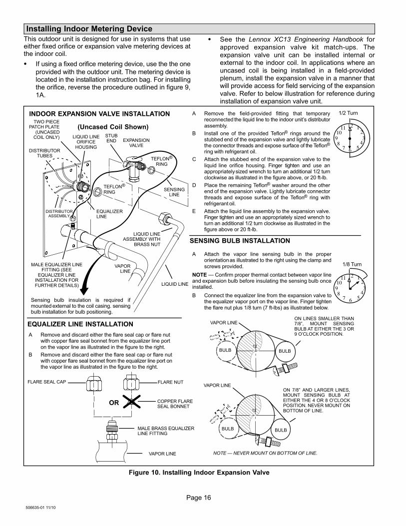
Installing Indoor Metering Device
This outdoor unit is designed for use in systems that useeither fixed orifice or expansion valve metering devices atthe indoor coil.
� If using a fixed orifice metering device, use the the one
provided with the outdoor unit. The metering device islocated in the installation instruction bag. For installingthe orifice, reverse the procedure outlined in figure 9,
1A.
� See the Lennox XC13 Engineering Handbook for
approved expansion valve kit match−ups. The
expansion valve unit can be installed internal orexternal to the indoor coil. In applications where an
uncased coil is being installed in a field−providedplenum, install the expansion valve in a manner thatwill provide access for field servicing of the expansion
valve. Refer to below illustration for reference duringinstallation of expansion valve unit.
A Attach the vapor line sensing bulb in the properorientation as illustrated to the right using the clamp andscrews provided.
NOTE � Confirm proper thermal contact between vapor lineand expansion bulb before insulating the sensing bulb onceinstalled.
B Connect the equalizer line from the expansion valve tothe equalizer vapor port on the vapor line. Finger tightenthe flare nut plus 1/8 turn (7 ft−lbs) as illustrated below.
TWO PIECEPATCH PLATE
(UNCASEDCOIL ONLY)
VAPORLINE
LIQUID LINEORIFICE
HOUSINGDISTRIBUTOR
TUBES
LIQUID LINE
MALE EQUALIZER LINEFITTING (SEE
EQUALIZER LINEINSTALLATION FORFURTHER DETAILS)
SENSINGLINE
EQUALIZERLINE
EXPANSIONVALVE
TEFLON®
RING
(Uncased Coil Shown)
Sensing bulb insulation is required ifmounted external to the coil casing. sensingbulb installation for bulb positioning.
STUBEND
TEFLON®
RING
LIQUID LINEASSEMBLY WITH
BRASS NUT
DISTRIBUTORASSEMBLY
A Remove the field−provided fitting that temporaryreconnected the liquid line to the indoor unit’s distributorassembly.
B Install one of the provided Teflon® rings around thestubbed end of the expansion valve and lightly lubricatethe connector threads and expose surface of the Teflon®
ring with refrigerant oil.
C Attach the stubbed end of the expansion valve to theliquid line orifice housing. Finger tighten and use anappropriately sized wrench to turn an additional 1/2 turnclockwise as illustrated in the figure above, or 20 ft−lb.
D Place the remaining Teflon® washer around the otherend of the expansion valve. Lightly lubricate connectorthreads and expose surface of the Teflon® ring withrefrigerant oil.
E Attach the liquid line assembly to the expansion valve.Finger tighten and use an appropriately sized wrench toturn an additional 1/2 turn clockwise as illustrated in thefigure above or 20 ft−lb.
ON 7/8" AND LARGER LINES,MOUNT SENSING BULB ATEITHER THE 4 OR 8 O’CLOCKPOSITION. NEVER MOUNT ONBOTTOM OF LINE.
12
ON LINES SMALLER THAN7/8", MOUNT SENSINGBULB AT EITHER THE 3 OR9 O’CLOCK POSITION.
12
BULB
VAPOR LINE
VAPOR LINE
NOTE � NEVER MOUNT ON BOTTOM OF LINE.
BULB
BULBBULB
VAPOR LINE
FLARE NUT
COPPER FLARESEAL BONNET
MALE BRASS EQUALIZERLINE FITTING
FLARE SEAL CAP
OR
123
4567
8910
11 12
1/2 Turn
SENSING BULB INSTALLATION
EQUALIZER LINE INSTALLATION
123
4567
8910
11 12
1/8 Turn
A Remove and discard either the flare seal cap or flare nutwith copper flare seal bonnet from the equalizer line porton the vapor line as illustrated in the figure to the right.
B Remove and discard either the flare seal cap or flare nutwith copper flare seal bonnet from the equalizer line port onthe vapor line as illustrated in the figure to the right.
INDOOR EXPANSION VALVE INSTALLATION
Figure 10. Installing Indoor Expansion Valve

Page 17
XC13 SERIES
IMPORTANTThe Environmental Protection Agency (EPA) prohibitsthe intentional venting of HFC refrigerants duringmaintenance, service, repair and disposal of appliance.Approved methods of recovery, recycling or reclaimingmust be followed.
IMPORTANTIf this unit is being matched with an approved line setor indoor unit coil which was previously charged withmineral oil, or if it is being matched with a coil whichwas manufactured before January of 1999, the coiland line set must be flushed prior to installation. Takecare to empty all existing traps. Polyol ester (POE) oilsare used in Lennox units charged with HFC−410Arefrigerant. Residual mineral oil can act as aninsulator, preventing proper heat transfer. It can alsoclog the expansion device, and reduce the systemperformance and capacity.Failure to properly flush the system per theinstructions below will void the warranty.
Leak Test Line Set and Indoor Coil
WARNINGWhen using a high pressure gas such asdry nitrogen to pressurize a refrigerationor air conditioning system, use aregulator that can control the pressuredown to 1 or 2 psig (6.9 to 13.8 kPa).
IMPORTANTLeak detector must be capable of sensing HFCrefrigerant.
WARNINGRefrigerant can be harmful if it is inhaled. Refrigerantmust be used and recovered responsibly.
Failure to follow this warning may result in personal injuryor death.
TO VAPORSERVICE VALVE
HFC−410A
MANIFOLD GAUGE SET
OUTDOOR UNIT
HIGHLOW
NITROGEN
A With both manifold valves closed, connect the cylinder of HFC−410A refrigerant to the center port of the manifold gauge set. Open the valveon the HFC−410A cylinder (vapor only).
B Open the high pressure side of the manifold to allow HFC−410A into the line set and indoor unit. Weigh in a trace amount of HFC−410A. [Atrace amount is a maximum of two ounces (57 g) refrigerant or three pounds (31 kPa) pressure]. Close the valve on the HFC−410A cylinderand the valve on the high pressure side of the manifold gauge set. Disconnect the HFC−410A cylinder.
C Connect a cylinder of dry nitrogen with a pressure regulating valve to the center port of the manifold gauge set.
D Adjust dry nitrogen pressure to 150 psig (1034 kPa). Open the valve on the high side of the manifold gauge set in order to pressurize the line setand the indoor unit.
E After a few minutes, open one of the service valve ports and verify that the refrigerant added to the system earlier is measurable with a leakdetector.
F After leak testing disconnect gauges from service ports.
After the line set has been connected to the indoor and outdoor units, check the line set connections and indoor unit for leaks. Use thefollowing procedure to test for leaks:
A Connect an HFC−410A manifold gauge set high pressurehose to the vapor valve service port.
NOTE � Normally, the high pressure hose is connected tothe liquid line port. However, connecting it to the vapor portbetter protects the manifold gauge set from high pressuredamage.
B With both manifold valves closed, connect the cylinder ofHFC−410A refrigerant to the center port of the manifold gaugeset.
NOTE � Later in the procedure,the HFC−410A container will bereplaced by the nitrogencontainer.
1CONNECT GAUGE SET
2TEST FOR LEAKS
AB
Figure 11. Leak Test

Page 18
506635−01 11/10
Evacuating Line Set and Indoor Coil
A Open both manifold valves and start the vacuum pump.
B Evacuate the line set and indoor unit to an absolute pressure of 23,000 microns (29.01 inches of mercury).
NOTE � During the early stages of evacuation, it is desirable to close the manifold gauge valve at least once. A rapid rise in pressure
indicates a relatively large leak. If this occurs, repeat the leak testing procedure.
NOTE � The term absolute pressure means the total actual pressure within a given volume or system, above the absolute zero ofpressure. Absolute pressure in a vacuum is equal to atmospheric pressure minus vacuum pressure.
C When the absolute pressure reaches 23,000 microns (29.01 inches of mercury), perform the following:
� Close manifold gauge valves
� Close valve on vacuum pump
� Turn off vacuum pump
� Disconnect manifold gauge center port hose from vacuum pump
� Attach manifold center port hose to a dry nitrogen cylinder with pressure regulator set to 150 psig (1034 kPa) and purge the hose.
� Open manifold gauge valves to break the vacuum in the line set and indoor unit.
� Close manifold gauge valves.
D Shut off the dry nitrogen cylinder and remove the manifold gauge hose from the cylinder. Open the manifold gauge valves to release thedry nitrogen from the line set and indoor unit.
E Reconnect the manifold gauge to the vacuum pump, turn the pump on, and continue to evacuate the line set and indoor unit until theabsolute pressure does not rise above 500 microns (29.9 inches of mercury) within a 20−minute period after shutting off the vacuum pumpand closing the manifold gauge valves.
F When the absolute pressure requirement above has been met, disconnect the manifold hose from the vacuum pump and connect it to anupright cylinder of HFC−410A refrigerant. Open the manifold gauge valve 1 to 2 psig in order to release the vacuum in the line set andindoor unit.
G Perform the following:
OUTDOOR
UNIT
TO VAPORSERVICE VALVE
TO LIQUID LINESERVICE VALVE
MICRONGAUGE
VACUUM PUMP
A34000 1/4 SAE TEE WITHSWIVEL COUPLER
500
MANIFOLDGAUGE SET
HFC−410A
RECOMMENDMINIMUM 3/8" HOSE
A Connect low side of manifold gauge setwith 1/4 SAE in−line tee to vapor lineservice valve
B Connect high side of manifold gaugeset to liquid line service valve
C Connect micron gauge availableconnector on the 1/4 SAE in−line tee.
D Connect the vacuum pump (withvacuum gauge) to the center port of themanifold gauge set. The center portline will be used later for both theHFC−410A and nitrogen containers.
HIGHLOW
12
34
56
78
910
11 12
1/6 TURN
NITROGEN
1CONNECT GAUGE SET
A
B
C
D
2EVACUATE THE SYSTEM
NOTE � Remove cores from service valves (if not already done).
� Close manifold gauge valves.
� Shut off HFC−410A cylinder.
� Reinstall service valve cores by removing manifold hose from service valve. Quickly install cores with core
tool while maintaining a positive system pressure.
� Replace stem caps and secure finger tight, then tighten an additional one−sixth (1/6) of a turn as illustrated.
Figure 12. Evacuating System

Page 19
XC13 SERIES
IMPORTANTUse a thermocouple or thermistor electronic vacuumgauge that is calibrated in microns. Use an instrumentcapable of accurately measuring down to 50 microns.
WARNINGDanger of Equipment Damage. Avoid deep vacuumoperation. Do not use compressors to evacuate asystem. Extremely low vacuums can cause internalarcing and compressor failure. Damage caused bydeep vacuum operation will void warranty.
Evacuating the system of non−condensables is critical forproper operation of the unit. Non−condensables aredefined as any gas that will not condense under
temperatures and pressures present during operation ofan air conditioning system. Non−condensables and watersuction combine with refrigerant to produce substancesthat corrode copper piping and compressor parts.
Electrical
In the U.S.A., wiring must conform with current local codesand the current National Electric Code (NEC). In Canada,wiring must conform with current local codes and the currentCanadian Electrical Code (CEC).
Refer to the furnace or air handler installation instructionsfor additional wiring application diagrams and refer to unitnameplate for minimum circuit ampacity and maximumovercurrent protection size.
24VAC TRANSFORMER
Use the transformer provided with the furnace or airhandler for low-voltage control power (24VAC − 40 VAminimum)
Refer to the unit nameplate for minimum circuit ampacity, andmaximum fuse or circuit breaker (HACR per NEC). Install powerwiring and properly sized disconnect switch.
NOTE � Units are approved for use only with copper conductors.Ground unit at disconnect switch or to an earth ground.
SIZE CIRCUIT AND INSTALL DISCONNECTSWITCH1
NOTE � 24VAC, Class II circuit connections are made in the controlpanel.
Install room thermostat (ordered separately) on an inside wallapproximately in the center of the conditioned area and 5 feet(1.5m) from the floor. It should not be installed on an outside wallor where it can be affected by sunlight or drafts.
THERMOSTAT
5 FEET(1.5M)
INSTALL THERMOSTAT
2
DISCONNECTSWITCH
MAIN FUSEBOX/BREAKER
PANEL
A Run 24VAC control wires through cutout with grommet.
B Run 24VAC control wires through wire tie.
C Make 24VAC control wire connections using field provided wirenuts.
D Tighten wire tie to security 24V control wiring.
HIGH VOLTAGE FIELD WIRING
LOW VOLTAGE (24V) FIELD WIRING
FACTORY WIRING
CUTOUT WITHGROMMET
NOTE − FOR PROPER VOLTAGES, SELECT THERMOSTAT WIRE (CONTROL WIRES)GAUGE PER TABLE ABOVE.
WIRE RUN LENGTH AWG# INSULATION TYPE
LESS THAN 100’ (30 METERS) 18 TEMPERATURE RATING
MORE THAN 100’ (30 METERS) 16 35ºC MINIMUM.
WIRE NUTS
BLA
CK
24V CONTROL WIRES
YE
LLO
W
TIGHTEN WIRE TIE
UNIT LOW VOLTAGE CONNECTIONS
NOTE − DO NOT BUNDLE ANY EXCESS 24VAC CONTROL WIRES INSIDE CONTROLBOX.
NOTE − WIRE TIE PROVIDES LOW VOLTAGE WIRE STRAIN RELIEF AND TO MAINTAINSEPARATION OF FIELD INSTALLED LOW AND HIGH VOLTAGE CIRCUITS.
A
B
C
D
3
Page 20
506635−01 11/10
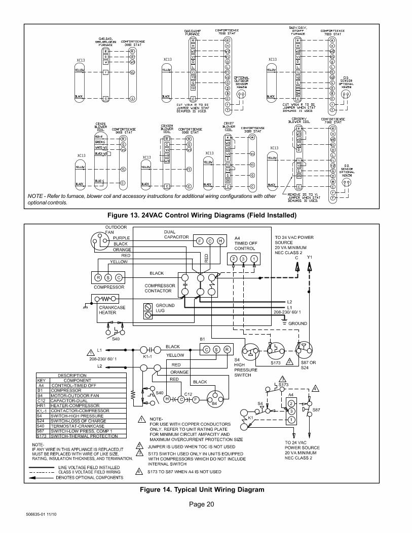
NOTE − Refer to furnace, blower coil and accessory instructions for additional wiring configurations with other
optional controls.
XC13 XC13 XC13
XC13
XC13
XC13XC13
Figure 13. 24VAC Control Wiring Diagrams (Field Installed)
Figure 14. Typical Unit Wiring Diagram

Page 21
XC13 SERIES
THERMAL PROTECTIONSWITCH (S5 OR S173)
HIGH PRESSURESWITCH (S4)
CRANKCASE THERMOSTAT (S40)CRANKCASE HEATER (HR1)
DUAL RUN CAPACITOR(C12)
FAN MOTOR (B4)
COMPRESSOR (B1)
CONTACTORK1
GROUND LUG
Figure 15. Typical Factory Wiring Diagram (Copland Compressor)
THERMAL PROTECTION SWITCH (S5 OR S173)
HIGH PRESSURESWITCH (S4)
CRANKCASE THERMOSTAT (S40)
CRANKCASE HEATER (HR1)
DUAL RUNCAPACITOR (C12)
FAN MOTOR (B4)
COMPRESSOR(B1)
CONTACTOR K1
GROUND LUG
Figure 16. Typical Factory Wiring Diagram (Interlink Compressor)
Page 22
506635−01 11/10
Servicing Units Delivered Void of Charge
If the outdoor unit is void of refrigerant, clean the systemusing the procedure described below.
1. Leak check system using procedure outlined on page17.
2. Evacuate the system using procedure outlined onpage 18.
3. Use nitrogen to break the vacuum and install a newfilter drier in the system.
4. Evacuate the system again using procedure outlinedon page 18.
5. Weigh in refrigerant using procedure outlined in figure20.
6. Monitor the system to determine the amount ofmoisture remaining in the oil. It may be necessary toreplace the filter drier several times to achieve therequired dryness level. If system dryness is notverified, the compressor will fail in the future.
Unit Start−Up
IMPORTANTIf unit is equipped with a crankcase heater, it should beenergized 24 hours before unit start−up to preventcompressor damage as a result of slugging.
1. Rotate fan to check for binding.
2. Inspect all factory− and field−installed wiring for looseconnections.
3. After evacuation is complete, open both the liquid andvapor line service valves to release the refrigerantcharge contained in outdoor unit into the system.
4. Replace the stem caps and tighten to the value listedin table 1.
5. Check voltage supply at the disconnect switch. Thevoltage must be within the range listed on the unit’snameplate. If not, do not start the equipment until youhave consulted with the power company and thevoltage condition has been corrected.
6. Set the thermostat for a cooling demand. Turn onpower to the indoor indoor unit and close the outdoorunit disconnect switch to start the unit.
7. Recheck voltage while the unit is running. Power mustbe within range shown on the nameplate.
8. Check system for sufficient refrigerant by using theprocedures listed under System Charge.
System Refrigerant
This section outlines procedures for:
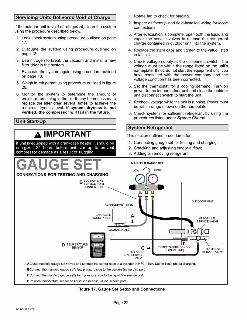
1. Connecting gauge set for testing and charging;
2. Checking and adjusting indoor airflow;
3. Adding or removing refrigerant.
TO LIQUIDLINE SERVICE
VALVE
TEMPERATURESENSOR
DIGITAL SCALE
REFRIGERANT TANK
TEMPERATURE SENSOR(LIQUID LINE)
MANIFOLD GAUGE SET
AClose manifold gauge set valves and connect the center hose to a cylinder of HFC−410A. Set for liquid phase charging.
BConnect the manifold gauge set’s low pressure side to the suction line service port.
CConnect the manifold gauge set’s high pressure side to the liquid line service port.
DPosition temperature sensor on liquid line near liquid line service port.
OUTDOOR UNIT
CHARGE INLIQUID PHASE
CONNECTIONS FOR TESTING AND CHARGING
GAUGE SET
A
CD
LOW HIGH
B SUCTION LINESERVICE PORTCONNECTION
VAPOR LINESERVICE VALVE
LIQUID LINESERVICE VALVE
Figure 17. Gauge Set Setup and Connections

Page 23
XC13 SERIES
WHEN TO CHARGE?
� Warm weather best
� Can charge in colder weather
CHARGE METHOD? Determine by:
� Metering device type
� Outdoor ambient temperature
REQUIREMENTS:
� Sufficient heat load in structure
� Indoor temperature between 70-80ºF(21−26ºC)
� Manifold gauge set connected to unit
� Thermometers:− to measure outdoor ambient temperature− to measure liquid line temperature− to measure suction line temperature
TXV FIXEDORIFICE
APPROACH ORSUBCOOLING
WEIGH-INSUPERHEAT
65ºF
(18.3ºC) and
Above
39ºF
(3.8ºC) and
Below
Which indoormeteringdevice?
WEIGH-IN
64ºF
(17.7ºC) and
Below
40ºF
(4.4ºC) and
Above
Figure 18. Determining Charge Method
CHECKING AIR FLOW AT INDOOR COIL
1. Determine the desired DT�Measure entering air temperatureusing dry bulb (A) and wet bulb (B). DT is the intersecting valueof A and B in the table (see triangle).
2. Find temperature drop across coil�Measure the coil’s dry bulbentering and leaving air temperatures (A and C). TemperatureDrop Formula: (TDrop) = A minus C.
3. Determine if fan needs adjustment�If the difference between themeasured TDrop and the desired DT (TDrop–DT) is within +3º, noadjustment is needed. See examples: Assume DT = 15 and Atemp. = 72º, these C temperatures would necessitate stated ac-tions:
Cº TDrop – DT = ºF ACTION
53º 19 – 15 = 4 Increase the airflow
58º 14 – 15 = −1 (within +3º range) no change
62º 10 – 15 = −5 Decrease the airflow
4. Adjust the fan speed�See indoor unit instructions to increase/decrease fan speed.
Changing air flow affects all temperatures; recheck temperaturesto confirm that the temperature drop and DT are within +3º.
DT80 24 24 24 23 23 22 22 22 20 19 18 17 16 15
78 23 23 23 22 22 21 21 20 19 18 17 16 15 14
76 22 22 22 21 21 20 19 19 18 17 16 15 14 13
74 21 21 21 20 19 19 18 17 16 16 15 14 13 12
72 20 20 19 18 17 17 16 15 15 14 13 12 11 10
70 19 19 18 18 17 17 16 15 15 14 13 12 11 10
57 58 59 60 61 62 63 64 65 66 67 68 69 70
Temp.of airenteringindoorcoil ºF
INDOORCOIL
DRYBULB
DRYBULB
WETBULB
B
TDrop
19º
A
Dry
−bu
lb
Wet−bulb ºF
A
72º
B
64º
C
53º
air flowair flow
All temperatures areexpressed in ºF
Figure 19. Checking Indoor Airflow over Evaporator Coil using Delta−T Chart
WEIGH IN
Liquid Line Set
DiameterOunces per 5 feet (g per 1.5 m) adjust from 15 feet (4.6
m) line set*
3/8" (9.5 mm) 3 ounce per 5’ (85 g per 1.5 m)
*If line length is greater than 15 ft. (4.6 m), add this amount. If line length is less than 15 ft. (4.6 m), subtract this amount.
Refrigerant Charge per Line Set Length
NOTE � The above nameplate is for illustration purposes only. Go to actual nameplate on outdoor unit for charge information.
CHARGING METHOD
NOTE � Insulate liquid line when it is routed through areas where the surrounding ambient temperature could become higher than thetemperature of the liquid line or when pressure drop is equal to or greater than 20 psig.
CALCULATING SYSTEM CHARGE FOR OUTDOOR UNIT VOID OF CHARGE
If the system is void of refrigerant, first, locate and repair any leaks and then weigh in the refrigerant charge into theunit. To calculate the total refrigerant charge:
Amount specified onnameplate
Adjust amount. for variationin line set length listed online set length table below.
Total charge
+ =64ºF (17.7ºC) and Below
Figure 20. Using HFC−410A Weigh In Method

Page 24
506635−01 11/10
DO NOT CHARGE UNIT
(Results of charging at lowtemperatures not reliable)
START: Measure outdoor ambient temperature
USE WEIGH-IN METHOD
Weigh-in or remove refrigerantbased upon line length
APPº (Approach) Values(F:+/−1.0° [C: +/−0.6°])
1. Connect gauge set as illustrated in figure 17.
2. Confirm proper airflow across coil using figure 19.
3. Compare unit pressures with table 4, NormalOperating Pressures.
4. Set thermostat to call for heat (must have a coolingload between 70-80ºF (21−26ºC).
5. When heat demand is satisfied, set thermostat to callfor cooling.
6. Allow temperatures and pressures to stabilize.
7. Record outdoor ambient temperature:
AMBº =_________
8. Record liquid line temperature:
LIQº = __________
9. Subtract to determine approach (APPº):
LIQº_____ − AMBº _____ = APPº_____
10. Compare results with table below.
Figure 21. Using HFC−410A Approach (TXV) Charge Method
64ºF and
BELOW
65ºF
and
ABOVE
ABOVE orBELOW
ºF (ºC)* −018 −024 −030 −036 −042 −048 −060
Any 4 (2.2) 8 (4.4) 8 (4.4) 11 (6.1) 7 (3.9) 8 (4.4) 9 (5.0)
*Temperature of air entering outdoor coil
APPROACH TXV
If value is greater than shown (high approach),
add refrigerant; if less than shown (liquid
temperature too close to ambient temperature,
low approach), remove refrigerant.
If refrigerant is added
or removed, retest to
confirm that unit is
properly charged.
DO NOT CHARGE UNIT
(Results of charging at lowtemperatures not reliable)
START: Measure outdoor ambient temperature
USE WEIGH-IN METHOD
Weigh-in or remove refrigerantbased upon line length
SCº (Subcooling) Values (F:+/−1.0° [C: +/−0.6°])
BLOCK OUTDOOR COIL: [sometimes necessary with lowertemperatures] Use cardboard or plastic sheet to restrict the airflowthrough the outdoor coil to achieve pressures from 325−375 psig(2240−2585 kPa). Higher pressures are needed to check charge. Blockequal sections of air intake panels and move coverings sideways untilthe liquid pressure is in the above noted ranges.
If value is MORE
than shown, remove
refrigerant.
1. Connect gauge set as illustrated in figure 17.
2. Confirm proper airflow across coil using figure 19.
3. Compare unit pressures with table 4, NormalOperating Pressures.
4. Set thermostat to call for heat (must have a coolingload between 70-80ºF (21−26ºC)
5. Measure outdoor ambient temperature
6. When heat demand is satisfied, set thermostat to callfor cooling
7. Allow temperatures and pressures to stabilize.
NOTE − If necessary, block outdoor coil to maintain
325 − 375 psig.
8. Record liquid line temperature:
LIQº = ______
9. Measure liquid line pressure and use the value todetermine saturation temperature (see table 3):
SATº = ______
10. Subtract to determine subcooling (SCº):
SATº_____ − LIQº _____ = SCº _____
11. Compare results with table below.
Figure 22. Using HFC−410A Subcooling (TXV) Charge Method
MORE orLESS
If refrigerant is added or
removed, verify charge
using the Approach
Method.
64ºF and
BELOW
65ºF
and
ABOVE
ABOVE orBELOW
If value is LESS
than shown, add
refrigerant.
Once refrigerant charge is
correct, disconnect gauge set
and replace service port caps.
ºF (ºC)* −018 −024 −030 −036 −042 −048 −060
Any 10 (5.6) 10 (5.6) 9 (5.0) 12 (6.7) 8 (4.4) 9 (5.0) 7 (3.9)
*Temperature of air entering outdoor coil
CARDBOARD ORPLASTIC SHEETS
SUBCOOLING TXV

Page 25
XC13 SERIES
START: Measure outdoor ambient temperature
NOTE − Do not attempt to charge system where adash appears, system could be overcharged.Superheat is taken at suction line service port.Suction line superheat must never be less than 5ºFat the suction line service port.
USE WEIGH-IN METHOD
Weigh-in or remove refrigerantbased upon line length
SHº (Superheat) Values (+/−5ºF)
Wet Bulb (air entering indoor coil)
ºF* 50 52 54 56 58 60 62 64 66 68 70 72 74 76
40 15 18 20 23 26 29 32 34 38 41 43 46 48 51
45 13 16 18 21 24 27 30 33 36 39 41 44 46 49
50 11 14 16 19 22 25 28 31 34 37 39 42 44 47
55 9 12 14 17 20 23 27 30 33 36 38 40 42 44
60 7 10 12 15 18 21 24 27 30 33 35 38 40 43
65 - 6 10 13 16 19 21 24 27 30 33 36 38 41
70 - - 7 10 13 16 19 21 24 27 30 33 36 39
75 - - - 6 9 12 15 18 21 24 28 31 34 37
80 - - - - 5 8 12 15 18 21 25 28 31 35
85 - - - - - - 8 11 15 19 22 26 30 33
90 - - - - - - 5 9 13 16 20 24 27 31
95 - - - - - - - 6 10 14 18 22 25 29
100 - - - - - - - - 8 12 16 21 24 28
105 - - - - - - - - 5 9 13 17 22 26
110 - - - - - - - - - 6 11 15 20 25
115 - - - - - - - - - - 8 14 18 24
* Dry−bulb temperature (ºF) of entering outdoor ambient air.
1. Confirm proper airflow across coil using figure 19.
2. Compare unit pressures with table 4, NormalOperating Pressures.
3. Use SUPERHEAT to correctly charge unit or toverify the charge is correct.
4. Set thermostat to call for heat (must have a coolingload between 70-80ºF (21−26ºC)
5. Connect gauge set.
6. When heat demand is satisfied, set thermostat tocall for cooling.
7. Allow temperatures and pressures to stabilize.
8. Measure the suction line pressure and use the usevalue to determine saturation temperature (table3):
SATº =_________
9. Record suction line temperature:
VAPº =_________
10. Subtract to determine superheat (SHº):
VAPº − _____ SATº ______ = SHº______
11. Record the wet bulb temperature (air enteringindoor coil):
WB =_______
12. Record outdoor ambient temperature.
13. Compare results with table to the left.
If value is MORE
than shown, then
ADD refrigerant.
If value is LESS than
shown, then REMOVE
refrigerant.
If refrigerant is
REMOVED, retest to
confirm that unit is
properly charged.
MORE orLESS
If refrigerant is
ADDED, retest to
confirm that unit is
properly charged.
ABOVE orBELOW39ºF and
BELOW
40ºF
and
ABOVE
Figure 23. Using HFC−410A Superheat (Fixed Orifice) Charge Method
Table 3. HFC−410A Temperature (°F) − Pressure (Psig)
°F Psig °F Psig °F Psig °F Psig °F Psig °F Psig °F Psig °F Psig
32 100.8 48 137.1 63 178.5 79 231.6 94 290.8 110 365.0 125 445.9 141 545.6
33 102.9 49 139.6 64 181.6 80 235.3 95 295.1 111 370.0 126 451.8 142 552.3
34 105.0 50 142.2 65 184.3 81 239.0 96 299.4 112 375.1 127 457.6 143 559.1
35 107.1 51 144.8 66 187.7 82 242.7 97 303.8 113 380.2 128 463.5 144 565.9
36 109.2 52 147.4 67 190.9 83 246.5 98 308.2 114 385.4 129 469.5 145 572.8
37 111.4 53 150.1 68 194.1 84 250.3 99 312.7 115 390.7 130 475.6 146 579.8
38 113.6 54 152.8 69 197.3 85 254.1 100 317.2 116 396.0 131 481.6 147 586.8
39 115.8 55 155.5 70 200.6 86 258.0 101 321.8 117 401.3 132 487.8 148 593.8
40 118.0 56 158.2 71 203.9 87 262.0 102 326.4 118 406.7 133 494.0 149 601.0
41 120.3 57 161.0 72 207.2 88 266.0 103 331.0 119 412.2 134 500.2 150 608.1
42 122.6 58 163.9 73 210.6 89 270.0 104 335.7 120 417.7 135 506.5 151 615.4
43 125.0 59 166.7 74 214.0 90 274.1 105 340.5 121 423.2 136 512.9 152 622.7
44 127.3 60 169.6 75 217.4 91 278.2 106 345.3 122 428.8 137 519.3 153 630.1
45 129.7 61 172.6 76 220.9 92 282.3 107 350.1 123 434.5 138 525.8 154 637.5
46 132.2 62 175.4 77 224.4 93 286.5 108 355.0 124 440.2 139 532.4 155 645.0
47 134.6 78 228.0 109 360.0 140 539.0
Page 26
506635−01 11/10
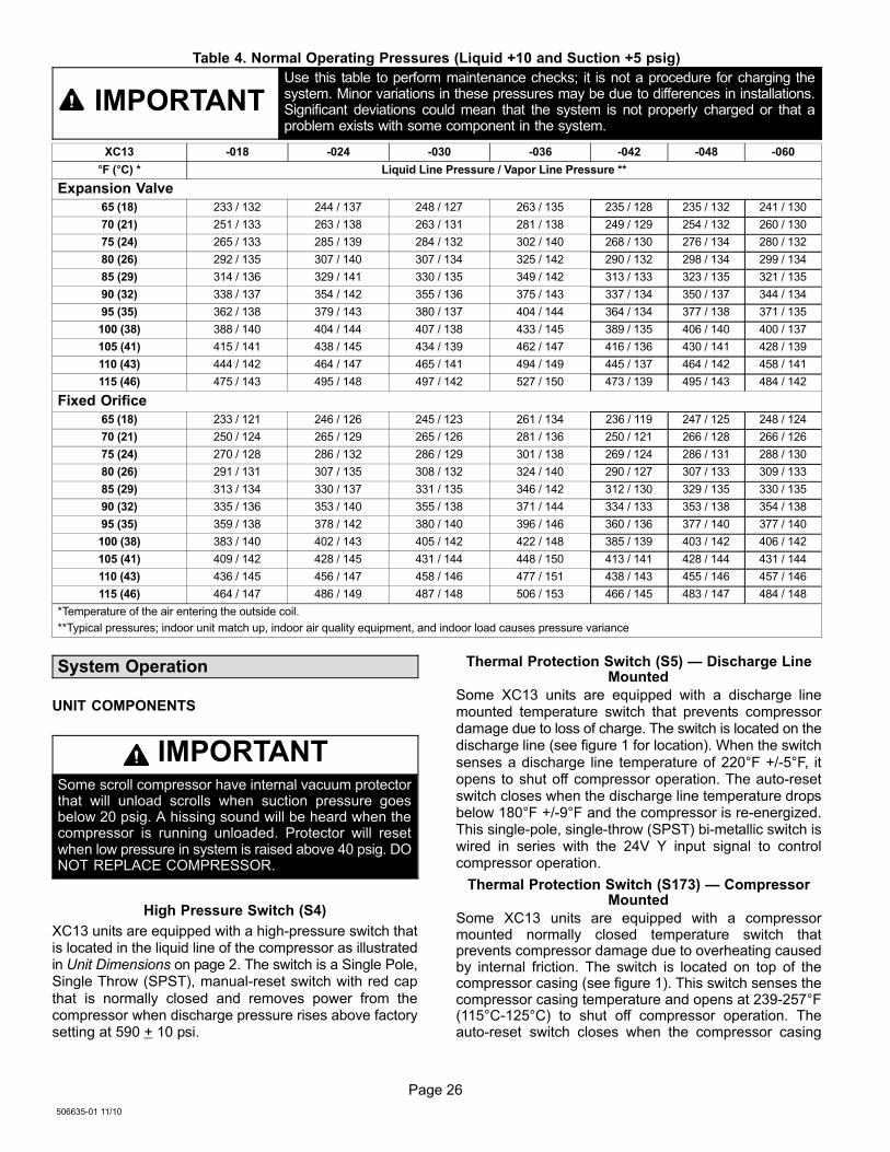
Table 4. Normal Operating Pressures (Liquid +10 and Suction +5 psig)
IMPORTANTUse this table to perform maintenance checks; it is not a procedure for charging thesystem. Minor variations in these pressures may be due to differences in installations.Significant deviations could mean that the system is not properly charged or that aproblem exists with some component in the system.
XC13 −018 −024 −030 −036 −042 −048 −060
�F (�C) * Liquid Line Pressure / Vapor Line Pressure **
Expansion Valve
65 (18) 233 / 132 244 / 137 248 / 127 263 / 135 235 / 128 235 / 132 241 / 130
70 (21) 251 / 133 263 / 138 263 / 131 281 / 138 249 / 129 254 / 132 260 / 130
75 (24) 265 / 133 285 / 139 284 / 132 302 / 140 268 / 130 276 / 134 280 / 132
80 (26) 292 / 135 307 / 140 307 / 134 325 / 142 290 / 132 298 / 134 299 / 134
85 (29) 314 / 136 329 / 141 330 / 135 349 / 142 313 / 133 323 / 135 321 / 135
90 (32) 338 / 137 354 / 142 355 / 136 375 / 143 337 / 134 350 / 137 344 / 134
95 (35) 362 / 138 379 / 143 380 / 137 404 / 144 364 / 134 377 / 138 371 / 135
100 (38) 388 / 140 404 / 144 407 / 138 433 / 145 389 / 135 406 / 140 400 / 137
105 (41) 415 / 141 438 / 145 434 / 139 462 / 147 416 / 136 430 / 141 428 / 139
110 (43) 444 / 142 464 / 147 465 / 141 494 / 149 445 / 137 464 / 142 458 / 141
115 (46) 475 / 143 495 / 148 497 / 142 527 / 150 473 / 139 495 / 143 484 / 142
Fixed Orifice
65 (18) 233 / 121 246 / 126 245 / 123 261 / 134 236 / 119 247 / 125 248 / 124
70 (21) 250 / 124 265 / 129 265 / 126 281 / 136 250 / 121 266 / 128 266 / 126
75 (24) 270 / 128 286 / 132 286 / 129 301 / 138 269 / 124 286 / 131 288 / 130
80 (26) 291 / 131 307 / 135 308 / 132 324 / 140 290 / 127 307 / 133 309 / 133
85 (29) 313 / 134 330 / 137 331 / 135 346 / 142 312 / 130 329 / 135 330 / 135
90 (32) 335 / 136 353 / 140 355 / 138 371 / 144 334 / 133 353 / 138 354 / 138
95 (35) 359 / 138 378 / 142 380 / 140 396 / 146 360 / 136 377 / 140 377 / 140
100 (38) 383 / 140 402 / 143 405 / 142 422 / 148 385 / 139 403 / 142 406 / 142
105 (41) 409 / 142 428 / 145 431 / 144 448 / 150 413 / 141 428 / 144 431 / 144
110 (43) 436 / 145 456 / 147 458 / 146 477 / 151 438 / 143 455 / 146 457 / 146
115 (46) 464 / 147 486 / 149 487 / 148 506 / 153 466 / 145 483 / 147 484 / 148
*Temperature of the air entering the outside coil.
**Typical pressures; indoor unit match up, indoor air quality equipment, and indoor load causes pressure variance
System Operation
UNIT COMPONENTS
IMPORTANTSome scroll compressor have internal vacuum protectorthat will unload scrolls when suction pressure goesbelow 20 psig. A hissing sound will be heard when thecompressor is running unloaded. Protector will resetwhen low pressure in system is raised above 40 psig. DONOT REPLACE COMPRESSOR.
High Pressure Switch (S4)
XC13 units are equipped with a high-pressure switch thatis located in the liquid line of the compressor as illustratedin Unit Dimensions on page 2. The switch is a Single Pole,Single Throw (SPST), manual−reset switch with red cap
that is normally closed and removes power from thecompressor when discharge pressure rises above factorysetting at 590 + 10 psi.
Thermal Protection Switch (S5) � Discharge LineMounted
Some XC13 units are equipped with a discharge linemounted temperature switch that prevents compressordamage due to loss of charge. The switch is located on thedischarge line (see figure 1 for location). When the switch
senses a discharge line temperature of 220°F +/−5°F, itopens to shut off compressor operation. The auto−resetswitch closes when the discharge line temperature dropsbelow 180°F +/−9°F and the compressor is re−energized.This single−pole, single−throw (SPST) bi−metallic switch iswired in series with the 24V Y input signal to controlcompressor operation.
Thermal Protection Switch (S173) � CompressorMounted
Some XC13 units are equipped with a compressormounted normally closed temperature switch thatprevents compressor damage due to overheating causedby internal friction. The switch is located on top of thecompressor casing (see figure 1). This switch senses thecompressor casing temperature and opens at 239−257°F(115°C−125°C) to shut off compressor operation. Theauto−reset switch closes when the compressor casing
Page 27
XC13 SERIES
temperature falls to 151−187°F (66°C−86°C), and thecompressor is re−energized. This single−pole, single−throw(SPST) bi−metallic switch is wired in series with the 24V Yinput signal to control compressor operation.
Crankcase Heater Thermostat (S40) (−060 only)
Compressor in the above reference units are equippedwith a 70 watt, belly band type crankcase heater. HR1prevents liquid from accumulating in the compressor. HR1is controlled by a thermostat located on the liquid line.
When liquid line temperature drops below 50°F thethermostat closes energizing HR1. The thermostat willopen, de−energizing HR1 once liquid line temperaturereaches 70°F .
Liquid Line Filter DrierA filter drier is factory-installed as illustrated in UnitDimensions on page 2, with each XC13 unit to ensure aclean, moisture−free system. A replacement filter drier isavailable from Lennox. Refer to Lennox Repair PartProgram.
Maintenance
DEALERMaintenance and service must be performed by a qualifiedinstaller or service agency. At the beginning of eachcooling season, the system should be checked as follows:
Outdoor Unit
1. Clean and inspect the outdoor coil. The coil may beflushed with a water hose. Ensure the power is turnedoff before you clean the coil.
2. Outdoor fan motor is prelubricated and sealed. Nofurther lubrication is needed.
3. Visually inspect connecting lines and coils forevidence of oil leaks.
4. Check wiring for loose connections.
5. Check for correct voltage at the unit (with the unitoperating).
6. Check amp−draw outdoor fan motor.
UNIT NAMEPLATE: _________ ACTUAL: __________
NOTE − If owner reports insufficient cooling, the unit should
be gauged and refrigerant charge checked.
Outdoor Coil
It may be necessary to flush the outdoor coil morefrequently if it is exposed to substances which arecorrosive or which block airflow across the coil (e.g., peturine, cottonwood seeds, fertilizers, fluids that may containhigh levels of corrosive chemicals such as salts)
� Outdoor Coil � The outdoor coil may be flushed with
a water hose.
� Outdoor Coil (Sea Coast) � Moist air in ocean
locations can carry salt, which is corrosive to mostmetal. Units that are located near the ocean require
frequent inspections and maintenance. Theseinspections will determine the necessary need to wash
the unit including the outdoor coil. Consult yourinstalling contractor for proper intervals/procedures
for your geographic area or service contract.
INDOOR UNIT
1. Clean or change filters.
2. Adjust blower speed for cooling. Measure the pressuredrop over the coil to determine the correct blower CFM.Refer to the unit information service manual for pressuredrop tables and procedure.
3. Check blower drive belt for wear and proper tension.
4. Check all wiring for loose connections
5. Check for correct voltage at unit (blower operating).
6. Check amp−draw on blower motor.
UNIT NAMEPLATE: _________ ACTUAL: __________
INDOOR COIL
1. Clean coil, if necessary.
2. Check connecting lines and coils for signs of oil leaks.
3. Check condensate line and clean, if necessary.
HOMEOWNERCleaning of the outdoor unit’s coil should be performed bya trained service technician. Contact your dealer and setup a schedule (preferably twice a year, but at least once ayear) to inspect and service your outdoor unit. Thefollowing maintenance may be performed by thehomeowner.
IMPORTANTSprinklers and soaker hoses should not be installedwhere they could cause prolonged exposure to theoutdoor unit by treated water. Prolonged exposure of theunit to treated water (i.e., sprinkler systems, soakers,waste water, etc.) will corrode the surface of steel andaluminum parts and diminish performance and longevityof the unit.
Outdoor Coil
The outdoor unit must be properly maintained to ensure itsproper operation.
� Please contact your dealer to schedule proper
inspection and maintenance for your equipment.
� Make sure no obstructions restrict airflow to the
outdoor unit.
� Grass clippings, leaves, or shrubs crowding the unit
can cause the unit to work harder and use moreenergy.
� Keep shrubbery trimmed away from the unit and
periodically check for debris which collects around theunit.
Cleaning of the outdoor unit’s coil should be performed bya trained service technician. Contact your dealer and setup a schedule (preferably twice a year, but at least once ayear) to inspect and service your outdoor unit.
Routine Maintenance
In order to ensure peak performance, your system must beproperly maintained. Clogged filters and blocked airflowprevent your unit from operating at its most efficient level.
1. Air Filter � Ask your Lennox dealer to show youwhere your indoor unit’s filter is located. It will be either
Page 28
506635−01 11/10
at the indoor unit (installed internal or external to thecabinet) or behind a return air grille in the wall orceiling. Check the filter monthly and clean or replaceit as needed.
2. Disposable Filter � Disposable filters should bereplaced with a filter of the same type and size.
NOTE � If you are unsure about the filter required for yoursystem, call your Lennox dealer for assistance.
3. Reusable Filter � Many indoor units are equippedwith reusable foam filters. Clean foam filters with amild soap and water solution; rinse thoroughly; allowfilter to dry completely before returning it to the unit orgrille.
NOTE � The filter and all access panels must be in placeany time the unit is in operation.
4. Indoor Unit � The indoor unit’s evaporator coil isequipped with a drain pan to collect condensateformed as your system removes humidity from theinside air. Have your dealer show you the location ofthe drain line and how to check for obstructions. (Thiswould also apply to an auxiliary drain, if installed.)
Thermostat Operation
See the thermostat homeowner manual for instructions onhow to operate your thermostat.
Preservice Check
If your system fails to operate, check the following beforecalling for service:
� Verify room thermostat settings are correct.
� Verify that all electrical disconnect switches are ON.
� Check for any blown fuses or tripped circuit breakers.
� Verify unit access panels are in place.
� Verify air filter is clean.
� If service is needed, locate and write down the unit
model number and have it handy before calling.
Accessories
For update−to−date information, see any of the followingpublications:
� Lennox XC13 Engineering Handbook
� Lennox Product Catalog
� Lennox Price Book
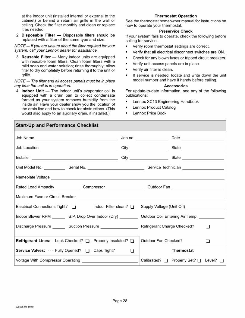
Start−Up and Performance Checklist
Job Name Job no. Date
Job Location City State
Installer City State
Unit Model No. Serial No. Service Technician
Nameplate Voltage
Rated Load Ampacity Compressor Outdoor Fan
Maximum Fuse or Circuit Breaker
Electrical Connections Tight? � Indoor Filter clean? � Supply Voltage (Unit Off)
Indoor Blower RPM S.P. Drop Over Indoor (Dry) Outdoor Coil Entering Air Temp.
Discharge Pressure Suction Pressure Refrigerant Charge Checked? �
Refrigerant Lines: Leak Checked? � Properly Insulated? � Outdoor Fan Checked? �
Service Valves: Fully Opened? � Caps Tight? � Thermostat
Voltage With Compressor Operating Calibrated? � Properly Set? � Level? �