Embed Size (px)
Citation preview

© 2010, AFL, all rights reserved. Revision 4, 2.6.15 Specifications are subject to change without notice.
345www.AFLglobal.com or 800-866-7385
HiTemp®
INST
ALL
ATIO
NIN
STRU
CTIO
NS
INS-ACA089
Installation InstructionsStandard Compression Dead End for ACSR and ACSS Conductor
1. Mark the conductor a distance of 3/4 the length of the aluminum body (Figure 1) .
2. Prior to making connection, the outer strands of the conductor must be cleaned with a wire brush or abrasive cloth (Figure 2) .
3. Prior to any strand cutting, tape the end of the conductor to help main-tain the round contour .
4. Slide the aluminum dead end body over conductor until sufficient work-ing length protrudes from tongue end . (Figure 3) .
5. Cut back aluminum strands equal to the depth of the steel forging bar-rel plus 1 inch (25 .4 mm) . Do not nick the steel strands . File burrs, if present . (Figure 4) . Use of a cable trimming tool is recommended . (Figure 4a, 4b) .
6. Insert steel core into steel barrel to full length of bore . (Figure 5) .
7. Using the proper SH die set, com-press steel barrel full length making initial compression adjacent to rib closest to barrel . Overlap each suc-cessive compression by at least ¼ inch (6 .4 mm) . Complete die closure is required on all compressions .(Figure 5a, 5b) .
8. Slide the aluminum body over the steel forging until the tongue end butts sol-idly against felt washer and shoulder of steel eye . Align eye with tongue to desired orientation for attachment to insulator string . (Figure 6) .
CAUTION: ACSR Dead Ends Cannot Be Used on ACSS HT Conductor
FIGURE 2: Clean a distance of at least ¾ the distance of the aluminum dead end body.
FIGURE 1: Mark the conductor and clean 3/4 the length of the aluminum body.
FIGURE 3: Slide aluminum dead end body over conductor.
FIGURE 4:
FIGURE 5: FIGURE 5a:
FIGURE 4a: FIGURE 4b:
FIGURE 5b: FIGURE 6:

© 2010, AFL, all rights reserved. Revision 4, 2.6.15 Specifications are subject to change without notice.
346www.AFLglobal.com or 800-866-7385
HiTemp®
INSTA
LLATION
INSTRU
CTION
S
INS-ACA089
Installation Instructions (cont.)
Standard Compression Dead End for ACSR and ACSS Conductor
9. Inject filler compound (AFC or AFCHT for HiTemp®) into filler hole until compound emerges at felt washer and tapered end of aluminum body . (Figure 6a) .
10. Insert and drive filler plug (cavity up) into hole and peen edge of hole over top surface of plug . (Figure 7) . Leav-ing the filler plug in the small plastic bag makes it easier to insert when working with gloves . (Figure 7a) .
11. Using the proper AH die set, make the initial compression on the alumi-num body beginning at the “start” mark nearest the tongue . Overlap each successive compression by at least ¼ inch (6 .4 mm) . Press only to the “stop” mark . Complete die clo-sure is required for each compression . (Figure 8) .
Note: A light oil coating on the die grooves and aluminum sleeve is recommended .
12. To press the dead end body over the conductor, use the same die used in step 11 . Begin compressing at the “start” mark about centrally located . Overlap each successive compression by at least ¼ inch (6 .4 mm) . Press to the end of the body, including the tapered portion . Complete die closure is required on each compression . (Figure 9) .
During this compression sequence, the plastic bag in which the dead end assembly was received can be used as a medium between the aluminum body and dies (instead of oil as men-tioned in step 11) .
13. Compressed portion of dead end body should have a smooth uniform appear-ance . (Figure 10) . If die flash is pres-ent, remove with a file or emery cloth .
14. Remove any excess filler compound which may have been forced out the end of the dead end body .
FIGURE 6a: FIGURE 7:
FIGURE 7a: FIGURE 8:
FIGURE 10: FIGURE 9:
Note the uncompressed section

347www.AFLglobal.com or 800-866-7385
HiTemp®
INST
ALL
ATIO
NIN
STRU
CTIO
NS
INS-ACA003
© 2010, AFL, all rights reserved. Revision 3, 3.5.13 Specifications are subject to change without notice.
1. Mark the conductor a distance of ½ the length of the aluminum sleeve (Figure 1) .
2. Prior to making connection, the outer strands of the conductor should be cleaned with a wire brush or abrasive cloth (Figure 2) .
3. Remark each conductor half the length of the aluminum sleeve, if the mark was removed during wire brushing . Prior to any strand cutting, tape the end of each conductor to help maintain the round contour (Figure 3) .
4. Slide the aluminum sleeve over one conductor until sufficient work-ing length protrudes from end (Figure 4) .
5. Cut back aluminum strands of both conductors ½ the length of the steel sleeve plus 1 ½ inch (38 .1 mm) . Do not nick the steel strands . File any burrs, if present (Figure 5a) . Use of a cable trimming tool is recom-mended (Figure 5b) .
6. Insert ends of steel core into steel sleeve making sure the ends butt solidly against center stop (Figure 6) .
7. Using the proper SH die set, com-press steel sleeve full length making initial compression over center of sleeve (Figure 7a), Overlap each successive compression by at least ¼ inch (6 .4 mm) (Figure 7b) . Complete die closure is required on all compressions .
FIGURE 2: Clean the outer strands of the conductor with a wire brush .
FIGURE 1: Mark the conductor and clean 1/2 the length of the sleeve .
FIGURE 3: Re-mark the conductors after cleaning if needed . FIGURE 4: Slide sleeve over one conductor so it protrudes out the end .
FIGURE 5a: Cut back the Aluminum strands on both conductors 1/2 the length of the Steel sleeve plus 1 1/2 inch (38 .1 mm) .
FIGURE 5b: Use of a cable trimming tool is recommended . FIGURE 6: Slide sleeve over one conductor so it protrudes out the end .
FIGURE 7a: Make the initial compression on center of Steel sleeve .
FIGURE 7b: Overlap each compression on Steel sleeve 1/4 inch (6 .4 mm) .
Installation InstructionsHiTemp Compression Splice for ACSS and ACSS/TW Conductors

© 2010, AFL, all rights reserved. Revision 3, 3.5.13 Specifications are subject to change without notice.
348www.AFLglobal.com or 800-866-7385
HiTemp®
INSTA
LLATION
INSTRU
CTION
S
INS-ACA003
8. Slide the aluminum sleeve over the installed steel sleeve, centering between the two marks that were made in Step 3 (Figure 8a & 8b) .
9. Inject AFCHT filler compound into filler hole until compound emerges from both ends of aluminum sleeve (Figure 9) .
10. Insert and drive filler plug (cavity up) into hole and peen edge of hole over top surface of plug . Leaving the filler plug in the small plastic bag makes it easier to insert when working with gloves (Figure 10a, 10b and 10c) .
11. Using the proper AH die set, make the initial compression at the “start” mark on one side of center (Figure 11a) . The second compression should be made at the other “start” mark on opposite side of center . Continue making compressions to the end, overlapping each by at least ¼ inch (6 .4 mm) (Figure 11b) . Repeat this on opposite side of joint (Figure 11c) . Complete die closure is required for each compression .
Note: A light oil coating on the die grooves and aluminum sleeve is recommended .
12. Compressed portion of splice sleeve
should have a smooth uniform appearance . If die flash is present, remove with a file or emery cloth (Figure 12) . Remove any excess filler compound which may have been forced out the ends of the splice .
FIGURE 8a: Slide the Aluminum sleeve over the installed Steel sleeve .
FIGURE 8b: Center the Aluminum sleeve between the marks .
FIGURE 9: Inject AFCHT Filler Compound into the filler hole . FIGURE 10a: Peen edge of filler hole over top surface of plug .
FIGURE 10c: Peen edge of filler hole over top surface of plug .FIGURE 10b: Filler plug left in plastic bag is easier to insert with gloves .
FIGURE 11a: Make the initial compression at the "start" mark . FIGURE 11b: Overlap each compression by 1/4 inch (6 .4 mm) .
FIGURE 11c: Completed compression splice . FIGURE 12: If die flash is present, remove with a file or emory cloth .
Installation Instructions (cont.)
HiTemp Compression Splice for ACSS and ACSS/TW Conductors

© 2010, AFL, all rights reserved. Revision 4, 2.6.15 Specifications are subject to change without notice.
349www.AFLglobal.com or 800-866-7385
HiTemp®
INST
ALL
ATIO
NIN
STRU
CTIO
NS
INS-ACA090
Installation Instructions HiTemp Repair Sleeves for ACSS and ACSS/TW Conductors
1 . Mark the conductor from the damaged area 1/2 the length of the repair sleeve .
2 . Compression repair sleeves can be used to restore the electrical and mechanical integrity of a conductor when no more than one-third of the outer aluminum strands are damaged .
3 . Select die size for compressing the repair sleeve . The die size on the die and the die size marked on the repair sleeve must be the same .
4 . Prior to making connections, the groove of the aluminum accessories and the conductor must be clean . If the conductor is weathered or blackened, clean strands thoroughly with wire brush or abrasive cloth . Check accessory groove for foreign particles, removing if present .
5 . Coat the aluminum conductor with HiTemp AFL Filler Compound (AFCHT) over the length to be covered by the repair sleeve .
6 . Place the repair sleeve groove on the conductor adjacent to damaged area and slide other half (keeper) in place .
7 . Slide repair sleeve assembly over the damaged area, to the mark on the conductor .
8 . Make the initial compression over the center portion of the repair sleeve . Make the second compression on one end overlapping the initial compression by 1/4 die bite . Make the third compression on the opposite end, overlapping the initial compression by 1/4 die bite . Continue making compressions to the end of the repair sleeve overlapping the previous compression by 1/4 die bite . Complete die closure is required for each compression . Go back and complete the compression on the opposite encl .
9 . The compressed repair sleeve should have a smooth uniform appearance . Remove flash, if present, with file or emery cloth .

© 2010, AFL, all rights reserved. Revision 4, 2.6.15 Specifications are subject to change without notice.
350www.AFLglobal.com or 800-866-7385
HiTemp®
INSTA
LLATION
INSTRU
CTION
S
INS-ACA091
Installation Instructions HiTemp Jumper Connectors for ACSS and ACSS/TW Conductors
1 . Measure back from each conductor end and mark at a distance equal to 1/2 the length of the aluminum jumper connector .
2 . File burrs or sharp edges off the aluminum strands as necessary for ease of insertion .
3 . Prior to making connections, the conductor and accessory bores must be clean . If the conductor Is weathered or blackened, carefully unlay aluminum strands for a distance equal to or greater than 1/2 the length of the aluminum jumper connector and clean strands thoroughly with wire brush or abrasive cloth . The outer layer of new conductor should be wire brushed 1/2 the length of the jumper . Check accessory bore for foreign particles, removing if present .
4 . Inject HiTemp AFL Filler Compound (AFCHT) into each end of jumper connector and on the conductor to insure that excess compound will be forced from the jumper connector when compressions are completed . Insert the conductor ends into the jumper connector . If the mark on the conductor is not at the end of the jumper connector, and there is resistance to further entry, twist the jumper connector on the conductor . This will work the compound between conductor strands and bleed air from the jumper connector .
5 . Select die size for compressing jumper connector . The die size on die and die size marked on aluminum jumper connector must be the same .
6 . The jumper connector must be supported a minimum of 15 feet on each side to prevent bowing during compression .
7 . Compress jumper connector full length making initial compression over center stop . Overlap each successive compression by approximately 1/4 die bite . Complete die closure is required for each compression .
8 . Compressed jumper connector should have a smooth uniform appearance . Remove flash, if present, with file or emery cloth .

www.AFLglobal.com or 800-866-7385
HiTemp®
351
INST
ALL
ATIO
NIN
STRU
CTIO
NS
INS-ACA032
© 2003, AFL, all rights reserved. Revision 3, 9.13.16 Specifications are subject to change without notice.
1 . Prior to making any connections, the conductor must be clean . For new conductor, the outside diameter shall be wire brushed to remove the aluminum oxidation . If the conductor is weathered or blackened, only the outside diameter can be wire brushed, due to the dead soft aluminum strands of the ACSS or ACSS/TW . Do not try to unlay the strands to clean the inner layers, as the strands will not lay back to its original form . The ConductaClean® ultrasonic cleaning unit is recommended to be used on new and weathered ACSS and ACSS/TW .
2 . Mark the conductor from the end, a distance equal to the compression length of the terminal .
HiTemp Compression
3 . Inject sufficient AFL HiTemp Filler Compound (AFCHT) or HiTemp® Universal Compound (HiTUC)in the end of the terminal bore and on the conductor to ensure that excess compound will be visible at terminal end when barrel is completely compressed . See chart below for proper amount of AFCHT or HiTUC required for each terminal size .
Installation Instructions for HiTemp® Compression Terminals
Start Knurl
Mark
AFCHT of HiTUC Filler Compound RequiredPartial Terminal Catalog Number lb. Grams (g)
5175 .XXXHT, 5675 .XXXHT, 5875 .XXXHT 0 .1 45
5176 .XXXHT, 5676 .XXXHT, 5876 .XXXHT 0 .1 45
5120 .XXXHT, 5620 .XXXHT, 5820 .XXXHT 0 .1 45
5124 .XXXHT, 5624 .XXXHT, 5824 .XXXHT 0 .2 91
5127 .XXXHT, 5627 .XXXHT, 5827 .XXXHT 0 .2 91
5130 .XXXHT, 5630 .XXXHT, 5830 .XXXHT 0 .3 136
5134 .XXXHT, 5634 .XXXHT, 5834 .XXXHT 0 .3 136
5136 .XXXHT, 5636 .XXXHT, 5836 .XXXHT 0 .4 181
5138 .XXXHT, 5638 .XXXHT, 5838 .XXXHT 0 .4 181
5140 .XXXHT, 5640 .XXXHT, 5840 .XXXHT 0 .4 181
5142 .XXXHT, 5642 .XXXHT, 5842 .XXXHT 0 .5 227
5144 .XXXHT, 5644 .XXXHT, 5844 .XXXHT 0 .5 227
5148 .XXXHT, 5648 .XXXHT, 5848 .XXXHT 0 .6 272
Continued
CAUTION: Follow installation instructions carefully. Improper installation can result in mechanical failure of the cable system and possible injury to persons handling or in the vicinity of the cable systems.

www.AFLglobal.com or 800-866-7385 © 2003, AFL, all rights reserved. Revision 3, 9.13.16 Specifications are subject to change without notice.
HiTemp®
352
INSTA
LLATION
INSTRU
CTION
S
INS-ACA032
CAUTION: Follow installation instructions carefully. Improper installation can result in mechanical failure of the cable system and possible injury to persons handling or in the vicinity of the cable systems.
4 . To compress, select the proper die size as stamped on the terminal connector .
5 . Compress the terminal, beginning at the “start knurl .” Continue compressing toward the end of the terminal . Complete die closure is required for each compression . Overlap the previous compression by approximately 1/4 die bite . It is recommended that die grooves be well lubricated with a lightweight oil . Oil coating should be maintained during entire compression operation . (Other acceptable mediums that can be used instead of oil are wax, soap or plastic bag the terminal shipped in .)
6 . Remove flash caused by die closure, if any, with a file .
To Attach Terminal Connector to Dead End or Tee Tap
7 . Clean contact surface of pads to be connected by wire brushing thoroughly and immediately coating with a thin film of HiTUC or Alnox . Do not use AFL Filler Compound (AFC) .
8 . Bolt terminal to dead end pad . Partially tighten all bolts and then re-tighten each bolt to the recommended torque:
Aluminum 1/2” bolts - 25 lb-ft (34 N .m) Stainless Steel 1/2” bolts - 40 lb-ft (54 N .m)
Installation Instructions for HiTemp® Compression Terminals (cont.)
Compress in this direction

© 2010, AFL, all rights reserved. Revision 4, 2.6.15 Specifications are subject to change without notice.
353www.AFLglobal.com or 800-866-7385
HiTemp®
INST
ALL
ATIO
NIN
STRU
CTIO
NS
INS-ACA092
Installation Instructions HiTemp Open Run Tee Taps and Tee Connectors for ACSS and ACSS/TW Conductors
1 . Remove the keeper .
2 . Select die size for compressing the aluminum run . The die size on the die and die size marked on the aluminum run must be the same .
3 . Prior to making connections, the groove of the aluminum accessories and the conductor must be clean . The conductor strands should be thoroughly cleaned with wire brush or abrasive cloth . Check the accessory groove for foreign particles, removing if present .
4 . Coat the aluminum conductor with HiTemp AFL Filler Compound (AFCHT) over the length to be covered by the tee tap .
5 . Place run groove on conductor and slide the keeper in place .
6 . Make initial compression on either side of run starting at the ‘start knurl’ . Make the second compression on the opposite end of the run at the ‘start knurl’ . Continue making compressions to the end of the tee overlapping the previous compression by approximately 1/4 die bite . Complete die closure is required for each compression . Go back and complete the compression on the opposite end .
7 . Compressed portion of tee should have a smooth uniform appearance . Remove flash, if present, with file or emery cloth .
Installation of "tee" with compression branch8 . Install run tee as before per steps 1-7 .
9 . Select die size for compressing aluminum branch . The die size on die and the die size on the branch must be the same .
10 . Insert conductor full depth into branch bore and mark conductor at end of branch . Remove conductor after marking .
11 . Inject sufficient HiTemp AFL Filler Compound (AFCHT) in the end of the branch bore and on the conductor to insure that excess compound will be visible at the branch end when completely compressed .
12 . Insert cleaned end of the conductor into the branch to the mark on the conductor .
13 . Make initial compression starting at the "start knurl ." Continue making compressions to mouth of the branch overlapping the previous compression by approximately 1/4 die bite . Complete die closure is required for each compression .
14 . Compressed portion of the branch should have a smooth uniform appearance . Remove flash, if present, with file or emery cloth .
www.AFLglobal.com or 800-866-7385Page 354
354
© 2011, AFL, all rights reserved. Revision 2, 2.6.15 Specifications are subject to change without notice.
HiTemp®
INS-ACA093
INSTA
LLATION
INSTRU
CTION
S
GENERAL INFORMATIONAFL vibration dampers are produced with carefully designed and controlled surface finishes for High Voltage use . To maintain this quality, the dampers should be protected, preferably in their shipping containers, from dirt and foreign material prior to installation . Handling in the field should be with care to avoid mechanical damage . AFL Vibration dampers may be installed without disassembly of the clamp parts .
VIBREC™ DAMPER RECOMMENDATION PROGRAMThe Vibrec damper recommendation program assists in damper requirements for transmis-sion and distribution lines . For more information contact the AFL Technical Support Team at 1 .800 .866 .7385 .
INSTALLATION PROCEDUREStep 1: (a) Obtain the damper spacing from AFL . (b) At the tangent tower, the centerline of the damper should be the specified
distance from the center of the suspension clamp . (c) At the dead end location, the centerline of the damper should be the specified distance from the mouth of the dead end .
Normally, for a phase conductor, a second damper is required at the dead end location; on a static wire, a second damper is usually not required at the dead end location . The centerline distance between the two dampers should be as specified .
Step 2: Loosen the bolt so that the clamp may be opened sufficiently to permit cable entry into the clamp groove . Note: The bolt need not
be removed .
Step 3: Hang the damper on the conductor at the proper spacing specified in Step 1 and tighten the bolt finger tight . For a multi-conductor bundle, the bolt head should be toward the center of the bundle .
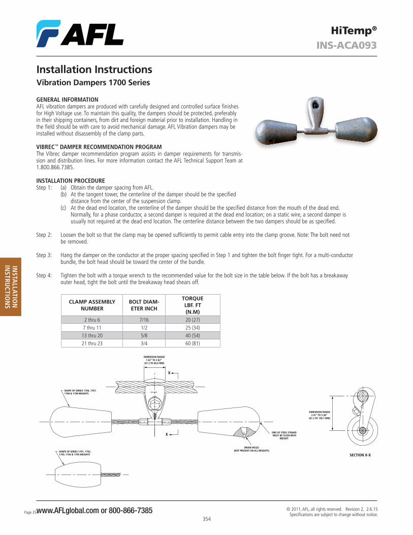
Step 4: Tighten the bolt with a torque wrench to the recommended value for the bolt size in the table below . If the bolt has a breakaway outer head, tight the bolt until the breakaway head shears off .
Installation InstructionsVibration Dampers 1700 Series
CLAMP ASSEMBLY NUMBER
BOLT DIAM-ETER INCH
TORQUELBF. FT(N.M)
2 thru 6 7/16 20 (27)7 thru 11 1/2 25 (34)13 thru 20 5/8 40 (54)21 thru 23 3/4 60 (81)
H
X
X END OF STEEL STRANDMUST BE FLUSH WITH
WEIGHT
-13-14-15
-15
SHAPE OF SERIES 1706, 1707,1708 & 1709 WEIGHTS
SHAPE OF SERIES 1701, 1702,1703, 1704 & 1705 WEIGHTS
DRAIN HOLES(NOT PRESENT ON ALL WEIGHTS)
SECTION X-X
DIMENSION RANGE2.41” TO 5.38”
(61.2 TO 136.7 MM)
DIMENSION RANGE1.62” TO 2.62”
(41.2 TO 66.6 MM)

www.AFLglobal.com or 800-866-7385355355
© 2011, AFL, all rights reserved. Revision 2, 2.6.15 Specifications are subject to change without notice.
HiTemp®
INS-ACA093
INST
ALL
ATIO
NIN
STRU
CTIO
NS
BARE CABLE WITH DAMPER PAIR
DAMPER ON BARE CABLE
BOLTED SUSPENSION
ARMOR RODS WITH DAMPER PAIR ON BARE CABLE
ARMOR RODS WITH DAMPER ON BARE CABLE
ARMOR RODS WITH DAMPER ON RODS
AGS WITH DAMPER PAIR OUTSIDE RODS
AGS WITH DAMPER ON RODS
AGS WITH DAMPER ON BARE CABLE
SPACING
SPACING
SPACING
OUTER RODS
SPACING
SPACING
SPACING SPACING
SPACING
SPACING
BOLTED DEAD END
DEAD END
DEAD END SPANS − PHASE CONDUCTORS
OPGW DEAD END WITH DAMPER PAIR
OPGW FORMED WIRE DEAD END (WEDGE) WITH DAMPER PAIR
OPGW FORMED WIRE DEAD END WITH DAMPER PAIR
COMPRESSION DEAD END WITH DAMPER ON BARE CABLE(STEEL SHIELD WIRE ONLY)
BOLTED STRAIN CLAMP WITH DAMPER ON BARE CABLE(STEEL SHIELD WIRE ONLY)
FORMED GRIP DEAD END WITH DAMPER ON BARE CABLE(STEEL SHIELD WIRE ONLY)
SPACING SPACING
SPACING SPACING
SPACING SPACING
SPACING
SPACING
SPACING
SPACING
SPACING
Installation Instructions (cont.)
Vibration Dampers 1700 Series

www.AFLglobal.com or 800-866-7385Page 356
356
© 2011, AFL, all rights reserved. Revision 2, 2.6.15 Specifications are subject to change without notice.
HiTemp®
INS-ACA093
INSTA
LLATION
INSTRU
CTION
S
BARE CABLE WITH DAMPER PAIR
DAMPER ON BARE CABLE
BOLTED SUSPENSION
ARMOR RODS WITH DAMPER PAIR ON BARE CABLE
ARMOR RODS WITH DAMPER ON BARE CABLE
ARMOR RODS WITH DAMPER ON RODS
AGS WITH DAMPER PAIR OUTSIDE RODS
AGS WITH DAMPER ON RODS
AGS WITH DAMPER ON BARE CABLE
SPACING
SPACING
SPACING
OUTER RODS
SPACING
SPACING
SPACING SPACING
SPACING
SPACING
BOLTED DEAD END
DEAD END
DEAD END SPANS − PHASE CONDUCTORS
OPGW DEAD END WITH DAMPER PAIR
OPGW FORMED WIRE DEAD END (WEDGE) WITH DAMPER PAIR
OPGW FORMED WIRE DEAD END WITH DAMPER PAIR
COMPRESSION DEAD END WITH DAMPER ON BARE CABLE(STEEL SHIELD WIRE ONLY)
BOLTED STRAIN CLAMP WITH DAMPER ON BARE CABLE(STEEL SHIELD WIRE ONLY)
FORMED GRIP DEAD END WITH DAMPER ON BARE CABLE(STEEL SHIELD WIRE ONLY)
SPACING SPACING
SPACING SPACING
SPACING SPACING
SPACING
SPACING
SPACING
SPACING
SPACING
Installation Instructions (cont.)
Vibration Dampers 1700 Series

www.AFLglobal.com or 800-866-7385357357
© 2011, AFL, all rights reserved. Revision 2, 2.6.15 Specifications are subject to change without notice.
HiTemp®
INS-ACA093
INST
ALL
ATIO
NIN
STRU
CTIO
NS
Installation Instructions (cont.)
Vibration Dampers 1700 Series
VIBRATION PROTECTION RECOMMENDATIONS – SPACING NOTES
Notes:1 . Tangent Spans – Phase Conductor and Overhead Ground Wire (OHGW) "Level One Damping” means one damper placement per conductor at one end of the span only . "Two dampers per conductor" means two
damper placements (one damper placement at each end of the span) .
2 . Tangent Spans – Dead End at One End – Phase Conductor In spans dead ended at one end only, and requiring only one damper per conductor, the damper should be placed at the tangent structure,
spaced in accordance with Dimension A or B . If the span requires three dampers per conductor, then one damper should be placed at the tangent structure, spaced in accordance with Dimension A or B, and two dampers should be placed at the deadended structure, spaced in accordance with Dimensions C and D . Normally, two dampers are recommended at conductor dead ends with insulator strings, as it is impossible to accurately predict the location of vibration node points relative to the conductor dead end . With just one damper at a dead end, the damper could, under certain wind conditions, be at a node point . The effectiveness of two dampers, spaced as recommended, assures that at least one of the two dampers will be effective at all times .
3 . Tangent Spans – Dead Ended at One End – Overhead Ground Wire In spans deadended at one end only, and requiring only one damper per wire, the damper should be placed at the tangent structure, spaced in
accordance with Dimension A or B . If the span requires two dampers per wire, then one damper should be placed at the tangent structure, in accordance with Dimension A or B, and one damper should be placed at the dead end, spaced in accordance with Dimension C .
4 . Spans Dead Ended at Both Ends – Phase Conductor "Two dampers per conductor" means two dampers at one end of the span only, spaced in accordance with Dimensions C and D . "Four damp-
ers per conductor" means two dampers at each end of the span, spaced in accordance with Dimensions C and D . Normally, two dampers are recommended at conductor dead ends with insulator strings, as it is impossible to accurately predict the location of vibration node points rela-tive to the conductor dead end . With just one damper at a dead end, the damper could, under certain wind conditions, be at a node point . The effectiveness of a damper on a node is significantly reduced . The use of two dampers, spaced as recommended, assures that at least one of the two dampers will be effective at all times .
5 . Spans Dead Ended at Both Ends – Overhead Ground Wire "One damper per conductor" means one damper at one end of the span, spaced in accordance with Dimension C . "Two dampers per conductor"
means one damper located at each end of the span, spaced in accordance with Dimension C .
6 . Spans Dead Ended at Both Ends, or Tangent Spans of Dead Ended at One End, For OHGW Utilizing a Formed Guy Grip Dead End We do not recommend the installation of damper clamps over formed-guy-grip type dead ends . Therefore, where vibration protection is required
for spans using the formed type dead ends, two dampers will be required at each dead end location, with the first damper spaced at the end of the rods and the second damper located in accordance with Dimension D .
7 . Dampers Over Armor Rods Dampers with the clamps placed over armor rods are not as effective as dampers with the clamp placed directly on the conductor . Therefore, if
armor rods are used, the rods should be short enough as to permit installation of the damper clamp over the bare conductor, using the recom-mended Dimension B spacing . The Dimension B is used whenever armor rods, line guards or AGS units are specified . In the event the rod lengths are too long to permit installation directly on the conductor, the damper clamp must be selected to fit over the installed rods .
8 . Selective Damping The ability of a damper to protect a given span may be hindered by vibration in adjacent undamped spans even though the vibration in the
undamped spans is not at a damaging level for the undamped span . Therefore, damping of adjacent spans is suggested at times . For simplicity, the Vibrec™ program recommends that spans adjacent to a span requiring dampers also be damped . AFL will, however, approve omission of dampers in spans shorter than the level zero limit when the adjacent damped spans are less than 50% of the one-damper limit .
9 . If there are any questions with respect to the damper recommendations or placement, contact your local representative .

www.AFLglobal.com or 800-866-7385
INS-ACA086HiTemp®
INSTA
LLATION
INSTRU
CTION
S
358
© 2011, AFL, all rights reserved. Revision 2, 2.6.15 Specifications are subject to change without notice.
Installation InstructionsSpeed-Grip® Spacers
1 . Prior to installation, slide open the spacer assembly giving a clamp opening of approximately 1½ times the conductor diameter . Finger-tighten the wedge-lock pin enough to hold the spacer assembly in the open position .
2 . Position spacer assembly between the two conductors, so that it is perpendicular to the conductors .
3 . Rotate the spacer assembly until the conductors rest in the open clamps .
4 . Loosen the wedge-lock pin and slide the spacer assembly closed . Finger-tighten the wedge-lock pin to engage the pin with lower spacer half lock hole .
5 . Using a 12” (30 cm) ratchet wrench with a 6-point deep socket, tighten the wedge-lock pin until breakaway head shears off .
6 . Make final visual inspection to ensure that the spacer is properly seated on the conductor, shear head is missing and the wedge-lock pin head is free of burrs .
Wedge Lock Pin
Half Lock Hole