Embed Size (px)
Citation preview
S Series ControlsCH5200P/CH5210P
w w w . s e a s t a r s o l u t i o n s . c o m
®
Before you do it your way,
please try it our way.
INSTALLATION INSTRUCTIONSAND OWNERS MANUAL
Part # 055000-049, Rev 3, 07/2013
Twin S ControlCH5200P
Single S ControlCH5210P
MANUFACTURED BYMARINE ACQUISITION INCORPORATED
DBA SEASTAR SOLUTIONSU.S.A.
MEMBER
ch2200ch2300
mt3osprey
pro-trimsingle stwin ssl-3
S SERIES CONTROLSCH5200P TWIN SCH5210P SINGLE SInstaller: these instructions contain important safety information and must be forwarded to the boat owner.
NOTICE
For use with Type 3300/33C cables.For use with Type 43C cables with the addition of Kit 042152 (1 kit per cable).
Cable installation and connections must be made in accordance with the motor manufacturer’s instructions.
To insure best performance, free operation of all linkages and the remote control is essential. Follow the manufacturer’s recommended procedures for adjustment and lubrication.
All specifications and features are subject to change without notice.
SeaStar Solutions highly recommends the installation and usage of an engine shut off switch as a important emergency safety feature for boats. This switch should be connected by a cord to the boat driver. Should the driver be thrown from the helm position, the engine will automatically shut off.
This shut off switch is not a standard part of the control you are using. It can, however, be obtained from most marine dealers and distributors.
The model “S” provides remote control operation of throttle or clutch of a gasoline or diesel inboard engine equipped with a hydraulic trans-mission. The “Twin S” can control both throttle and clutch of a single engine. Dual station control from both the cabin and the bridge is obtained by using “S” or “Twin S” controls connected in tandem or par-allel. SeaStar Solutions 3300/33C Xtreme cables are recommended in dual station installations for best results. These controls can be used in combination for any desired grouping of the clutch and throttle func-tions (see Table 1).
WARNING
Before starting installation read these instructions and engine makers instructions thoroughly. Failure to follow either of these instructions or incorrect assembly can result in loss of control and cause property damage, injury, or death.
DO NOT substitute parts from other manufacturers, they may cause a safety hazard for which SeaStar Solutions cannot accept responsibility.
WARNING
WARNING
Page 2 of 8 SeaStar Solutions Installation Instructions and Owner’s Manual Telephone: 610-495-7011
Control Head LocationTABLE 1
COMPONENTSSINGLESTATION
DUALSTATION
“S” “TWIN S” “S” “TWIN S”
Clutch Connection KitTrans EndThrottle Connection KitEngine End3300/33C Cables33C Xtreme Cables
1
1
11
1
1
22
1
1
—4
1
1
—4
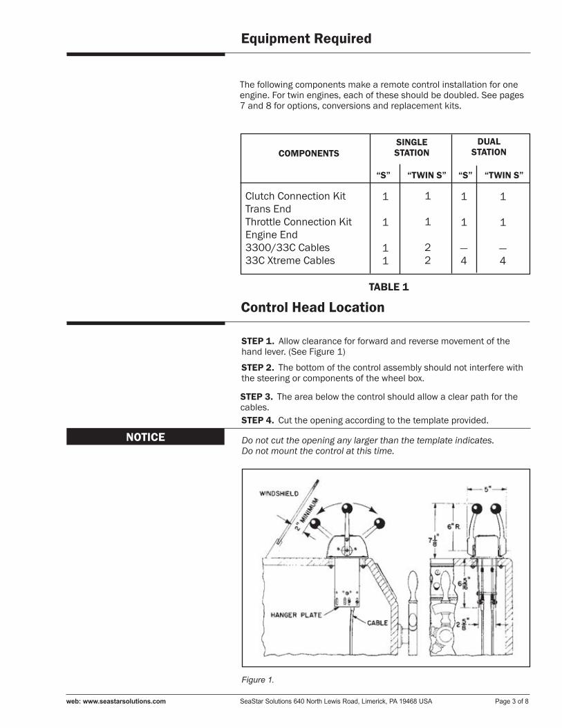
STEP 1. Allow clearance for forward and reverse movement of the hand lever. (See Figure 1)
STEP 2. The bottom of the control assembly should not interfere with the steering or components of the wheel box.
STEP 3. The area below the control should allow a clear path for the cables.STEP 4. Cut the opening according to the template provided.
NOTICE Do not cut the opening any larger than the template indicates.Do not mount the control at this time.
Figure 1.
The following components make a remote control installation for one engine. For twin engines, each of these should be doubled. See pages 7 and 8 for options, conversions and replacement kits.
Equipment Required
web: www.seastarsolutions.com SeaStar Solutions 640 North Lewis Road, Limerick, PA 19468 USA Page 3 of 8
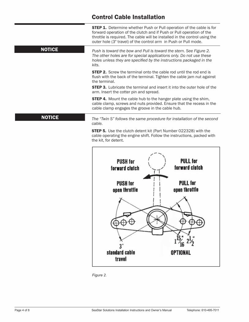
Control Cable Installation STEP 1. Determine whether Push or Pull operation of the cable is for forward operation of the clutch and if Push or Pull operation of the throttle is required. The cable will be installed in the control using the outer hole (3" travel) of the control arm in Push or Pull mode.
NOTICE Push is toward the bow and Pull is toward the stern. See Figure 2.The other holes are for special applications only. Do not use these holes unless they are specified by the instructions packaged in the kits.
STEP 2. Screw the terminal onto the cable rod until the rod end is flush with the back of the terminal. Tighten the cable jam nut against the terminal.STEP 3. Lubricate the terminal and insert it into the outer hole of the arm. Insert the cotter pin and spread.
STEP 4. Mount the cable hub to the hanger plate using the shim, cable clamp, screws and nuts provided. Ensure that the recess in the cable clamp engages the groove in the cable hub.
NOTICE The “Twin S” follows the same procedure for installation of the second cable.
STEP 5. Use the clutch detent kit (Part Number 022328) with the cable operating the engine shift. Follow the instructions, packed with the kit, for detent.
Figure 2.
Page 4 of 8 SeaStar Solutions Installation Instructions and Owner’s Manual Telephone: 610-495-7011
Mounting the Control HeadSTEP 1. Feed the control cables thru the opening cut out to the engine throttle and clutch levers.
Always run the cables as straight as possible. Avoid all sharp bends (8in. [203.2mm] minimum radius) with as few bends as possible.
CAUTION
STEP 2. Fasten the controls to the console with the hardware pro-vided.
Connecting the Cables to the EngineSTEP 1. Install the correct engine throttle and clutch connection kits to the engine if not provided with the engine.STEP 2. Connect the cables to the engine using the engine connection kit instructions or as provided by the engine manufacturer.
Final Adjustment
STEP 1. Operate the clutch hand lever. The detent positions and the clutch lever detents of the transmission must coincide exactly at forward, neutral and reverse positions. Adjust the cable terminal at the transmission, if necessary, to obtain correct operation.
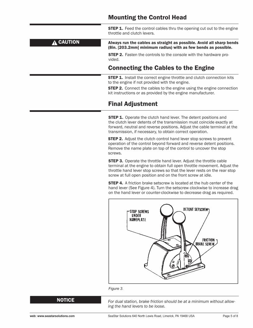
STEP 2. Adjust the clutch control hand lever stop screws to prevent operation of the control beyond forward and reverse detent positions. Remove the name plate on top of the control to uncover the stop screws.
STEP 3. Operate the throttle hand lever. Adjust the throttle cable terminal at the engine to obtain full open throttle movement. Adjust the throttle hand lever stop screws so that the lever rests on the rear stop screw at full open position and on the front screw at idle.
STEP 4. A friction brake setscrew is located at the hub center of the hand lever (See Figure 4). Turn the setscrew clockwise to increase drag on the hand lever or counter-clockwise to decrease drag as required.
NOTICE For dual station, brake friction should be at a minimum without allow-ing the hand levers to be loose.
Figure 3.
web: www.seastarsolutions.com SeaStar Solutions 640 North Lewis Road, Limerick, PA 19468 USA Page 5 of 8
Complete Installation of the ControlSTEP 1. Tighten the cable jam nuts securely at the terminals on both ends of the cable.
STEP 2. Apply light film of waterproof marine grease to all moving parts just installed.
STEP 3. Secure all cable supports but do not crush the cable.
STEP 4. Check the control levers. They should operate freely with light hand pressure. Binding of the levers could be traced to:1. Excessive number of cable bends2. Sharp cable bend(s) 3. Bends smaller than 8” min. radius4. Cable supports clamped too tight5. Damaged cable6. Friction brakes too tight7. Tight/misaligned engine linkage
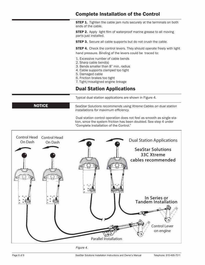
Dual Station ApplicationsTypical dual station applications are shown in Figure 4.
Dual station control operation does not feel as smooth as single sta-tion, since the system friction has been doubled. See step 4 under “Complete Installation of the Control.”
NOTICE SeaStar Solutions recommends using Xtreme Cables on dual station installations for maximum efficiency.
Figure 4.
Page 6 of 8 SeaStar Solutions Installation Instructions and Owner’s Manual Telephone: 610-495-7011
Heavy Duty
Heavy duty kits are available to attach SeaStar Solutions 4300 cables to the “S” controls, if desired. 4300 cables have a higher strength capacity, but 3300/33C cables are recommended for the most efficient system.
Maintenance
For the best protection, especially in salt water, wipe all metal parts with oil or a good quality light marine grease. Always rinse with fresh water after every use.
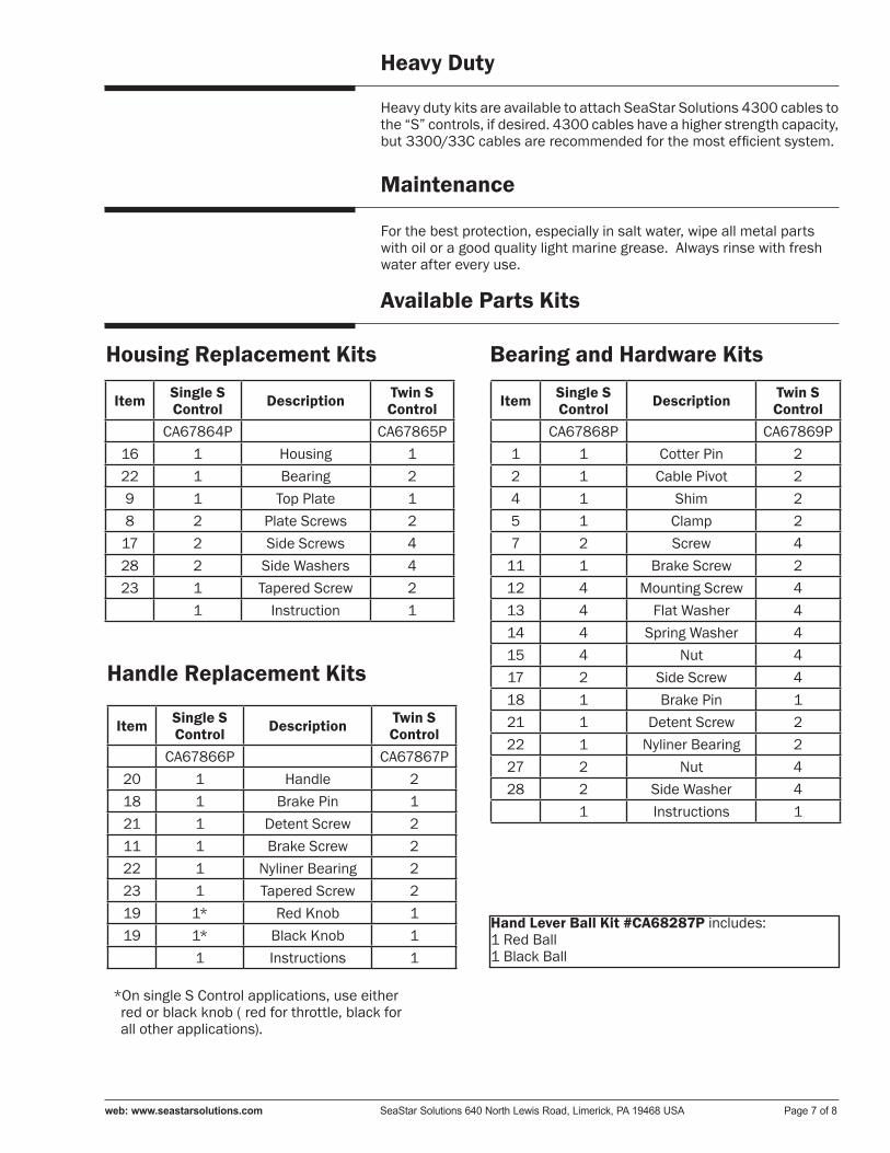
Available Parts Kits
Housing Replacement Kits Bearing and Hardware Kits
Handle Replacement Kits
Hand Lever Ball Kit #CA68287P includes:1 Red Ball1 Black Ball
Item Single SControl Description Twin S
ControlCA67864P CA67865P
16 1 Housing 122 1 Bearing 29 1 Top Plate 18 2 Plate Screws 2
17 2 Side Screws 428 2 Side Washers 423 1 Tapered Screw 2
1 Instruction 1
Item Single SControl Description Twin S
ControlCA67866P CA67867P
20 1 Handle 218 1 Brake Pin 121 1 Detent Screw 211 1 Brake Screw 222 1 Nyliner Bearing 223 1 Tapered Screw 219 1* Red Knob 119 1* Black Knob 1
1 Instructions 1
Item Single SControl Description Twin S
ControlCA67868P CA67869P
1 1 Cotter Pin 22 1 Cable Pivot 24 1 Shim 25 1 Clamp 27 2 Screw 4
11 1 Brake Screw 212 4 Mounting Screw 413 4 Flat Washer 414 4 Spring Washer 415 4 Nut 417 2 Side Screw 418 1 Brake Pin 121 1 Detent Screw 222 1 Nyliner Bearing 227 2 Nut 428 2 Side Washer 4
1 Instructions 1
*On single S Control applications, use either red or black knob ( red for throttle, black for all other applications).
web: www.seastarsolutions.com SeaStar Solutions 640 North Lewis Road, Limerick, PA 19468 USA Page 7 of 8
© 1967 MARINE ACQUISITION (US) INC.
PART NO. 055000-049 07-2013 Rev. 3
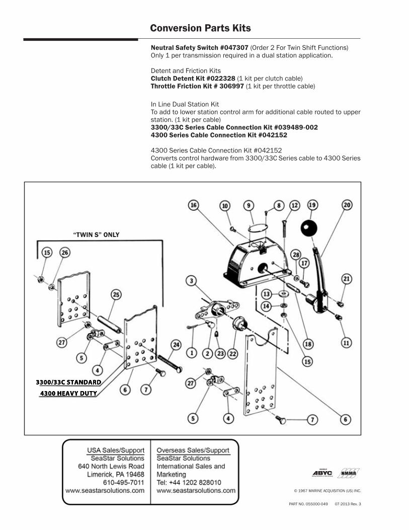
Conversion Parts Kits
Neutral Safety Switch #047307 (Order 2 For Twin Shift Functions)Only 1 per transmission required in a dual station application.
Detent and Friction KitsClutch Detent Kit #022328 (1 kit per clutch cable)Throttle Friction Kit # 306997 (1 kit per throttle cable)
In Line Dual Station Kit To add to lower station control arm for additional cable routed to upper station. (1 kit per cable)3300/33C Series Cable Connection Kit #039489-0024300 Series Cable Connection Kit #042152
4300 Series Cable Connection Kit #042152Converts control hardware from 3300/33C Series cable to 4300 Series cable (1 kit per cable).
4300 HEAVY DUTY
3300/33C STANDARD
“TWIN S” ONLY