Embed Size (px)
Citation preview

Installation InstructionsAOD Transmissions
© 2014, 1995 B&M Racing & Performance Products
Congratulations, you have purchased the best automatic transmission available. We at B&M are proud of our products and our long history of customer satisfaction. We have carefully tested this transmission at the factory to ensure that it operated fl aw-lessly before it was delivered. If installed and adjusted properly, this transmission will provide you with trouble free perfor-mance. If not installed or adjusted properly this unit could fail almost immediately.
Please take a minute to read theimportant information shipped with
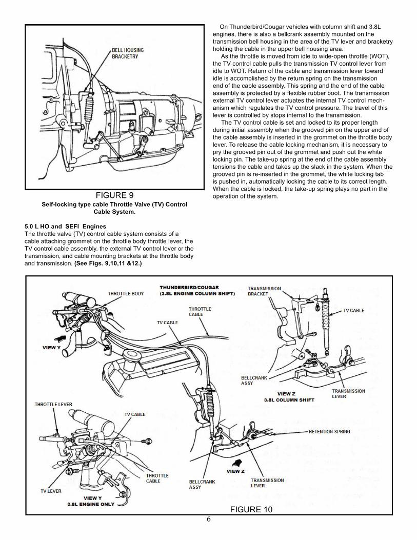
your transmission.1. The transmission and converter must be fi lled with transmission fl uid BEFORE the vehicle is started or even the engine is turned over. For example, if you also did engine work, don’t set the valves etc. which require the engine to be rotated without having the transmission fl uid al-ready in the transmission! We recommend B&M Trick Shift (#80259) or alternatively you may use any Mercon type fl uid.2. The transmission will fail if not con-nected to a transmission oil cooler that is adequate for the vehicle and converter stall speed. For extremely mild applications, the factory oil cooler in the vehicles radiator may be adequate, but for performance, street/strip or racing only applications an additional cooler must be used to remove the heat generated by a higher stall speed torque converter. Heat is one of the most damaging elements to an automatic trans-mission. Use the biggest and best cooler that you can to extend the life of the trans-mission. We recommend our SuperCooler series of “stack plate” design units. They are the strongest and most effi cient units on the market.3. If this transmission is replacing a failed unit, the transmission cooler lines and cooler must be reverse fl ushed to com-pletely remove the debris from the radiator cooler and lines. Failure to do so will almost certainly cause a failure in your new
B&M transmission.4. If the torque converter that you will be using is not new, be sure to have it professionally fl ushed before installing it. Debris from the previous transmission will contaminate the new transmission. This contamination could cause a failure in your new B&M transmission, such as wiped out bushings, bearings or stuck valves in the valve body. Additionally, inspect the pump drive tube for un-even or excessive wear as well as nicks or burrs. Any of these ailments will cause front pump failure very quickly. Unless you are very confi dent that the old converter is perfect, you should re-place it before reusing it with your newtransmission.5. AOD transmissions are extremely sensitive to proper Throttle Valve linkage/cable adjustment. Proper adjustment of
this linkage/cable is the most critical step of your installation. BE SURE TO CARE-FULLY READ THE INSTRUCTIONS IN THIS MANUAL THAT RELATE TO THIS ADJUSTMENT!
B&M Torque ConvertersIn addition to the AOD Split Path Hole-shot2000 torque converter, B&M also offers Holeshot 2400 and 3000 Open style torque converters for AOD transmis-sions. B&M’s Open style AOD converters eliminate the Split Path feature of stock converters and do not require any spe-cial transmission modifi cations, such as changing the transmissions input shaft. This makes changing to this style convert-er a much easier, less expensive bolt on operation.
Figure 1 1 9500564 REV01 07/14

Three different types of Throttle Valve (TV) linkages have been used on the Ford AOD transmission since its introduction. The earliest linkage consisted of a bent rigid rod connecting the car-buretor and transmission while most late model AOD’s use one of two different fl exible cable type linkages. NOTE: Special tools and a pressure gauge will be required depending on the particular TV linkage type you are working on. Adjustment procedure for each of the TV linkage types are presented in the following sections.1. Carburetor adjustment Perform the following steps prior to adjusting TV linkage.1.1 Check/adjust the engine curb idle speed to specifi ca tion. Refer to the Engine/Emissions Diagnosis manual for pro- cedures to adjust throttle solenoid applications. Make sure the curb idle speed is set to specifi cation with and without the throttle solenoid positioner (anti dieseling solenoid) energized, if so equipped.1.2 Shut engine off. Remove air cleaner.1.3 De-cam the fast idle cam on the carburetor so that the throttle lever is against the idle stop or throttle solenoid positioner stop.
Rod type TV control system.
The TV control linkage system consists of a linkage lever on the carburetor, the TV control rod assembly and an external TV control lever on the transmission. (See Fig. 2). The TV control rod transmits motion between the carburetor linkage lever and the TV control lever on the transmission. The carburetor linkage lever has an adjust ment screw for limited TV linkage Adjustment. The exter-nal TV control lever actuates the internal TV control mechanism which regulates TV control pressure.The TV control rod is set to its proper length during initial assem-bly using the sliding trunnion block at the transmission end of the TV control rod assembly. Under normal circumstances it should not be necessary to alter this adjustment. Any required adjustment can normally be made using the adjustment screw on the carbure-tor linkage lever.When the linkage is correctly adjusted, the TV control lever on the transmission will be at its internal stop position when the car-buretor lever is at its minimum idle stop. There will be light contact force between the throttle lever and the end of the linkage lever adjustment screw. Due to the fl exibility in the TV linkage, the ad-justment screw would have to be backed out several turns before a gap between the screw and throttle lever could be detected.Before any engine TV linkage adjustment can be done, the throttle lever at the carburetor (or throttle body) must be positioned at its minimum idle stop.2. Linkage Adjustment at CarburetorAdjust the TV control linkage at the carburetor using the following procedure (See Fig. 2):
2.1
2.2
2.3
2.4
2.5
Set carburetor at minimum idle stop as described in steps 1 thru Place shift lever in NEUTRAL and set parking brake. CAUTION: The transmission selector lever must be in NEUTRAL when adjusting the TV linkage.Back (turn CCW) the linkage lever adjusting screw all the way out (until screw end is fl ush with lever face).Turn the adjusting screw in (CW) until a thin shim of.127mm (0.005 inch) maximum, or piece of writing paper fi ts snug between end of screw and throttle lever. NOTE: To eliminate effect of friction, push linkage lever forward (tending to close gap) and re lease before checking clearance between end of screw and throttle lever. Do not apply any load on levers with tools or hands while checking gap.Turn the adjusting screw in (CW) an additional threeturns. (Three turns are preferred. One turn minimum is permis-sible if screw travel is limited).lf it is not possible to turn in adjusting screw at least one ad-ditional turn (from initial gap) or if there was insuffi cient screw adjusting capacity to obtain an initial gap in Step 5, refer to Linkage Adjustment at Transmis sion.
Idle Speed AdjustmentWhenever it is required to adjust idle speed by more than50 rpm, the adjustment screw on the linkage lever at the car-buretor should also be re-adjusted as follows:Idle Speed Change Linkage Adjustment at Carburetor50 rpm or more Check TV lever adjustmentdecrease at carburetorLess than 50 rpm No change required50 rpm or more Check TV lever adjustment increase at carburetorAfter making any idle speed adjustments, always verify that the linkage lever and throttle lever are in contact with the throttle lever at its idle stop (or throttle solenoid positioner) and the shift lever is in NEUTRAL.3. Rod Linkage Adjustment at Transmission
FIGURE 2
2

The linkage lever adjustment screw has limited adjust ment ca-pability. (See Fig. 2.) If it is not possible to adjust the TV linkage using this screw, the length of the TV control rod assembly must be re-adjusted using the follow ing procedure. This procedure must also be followed whenever a new TV control rod assembly is installed.This procedure requires raising the vehicle to give access to the linkage components at the transmission TV control lever.3.1 Set carburetor at its minimum idle stop as described in steps 1.1-1.3. Place shift lever in NEUTRAL and set parking brake. Turn engine off.3.2 Set the carburetor linkage lever adjustment screw at approx imately half-travel. 3.3 If a new TV control rod assembly is being installed, connect the rod to the linkage lever at the carburetor. CAUTION: The following steps involve working in close proximity to the exhaust system. Allow the exhaust system to cool before proceeding.3.4 Raise vehicle so there is at least 2 feet ground clear ance for ease of access. MAKE SURE THE VEHICLE IS RIGIDLY SUP-PORTED ON JACK STANDS OR WHEEL RAMPS IF A HOIST IS NOT AVAILABLE. DO NOT USE JACKS ALONE TO SUPPORT VE HICLE.3.5 Loosen the bolt on the sliding trunnion block on the TV control rod assembly. Remove corrosion and road grime from the control rod and free-up the trunnion block so that it slides freely on the control rod.3.6 Push up on the lower end of the control rod to ensure that the linkage lever at the carburetor is touching fi rmly against the throttle lever. Release force on rod. Rod must stay up.3.7 Push the TV control lever on the transmission up against its internal stop with a fi rm force, approxi mately 22 N (5 Ibs). Tighten the bolt on the trunnion block. Do not relax force on lever until bolt is tightened.3.8 Lower the vehicle and verify that the throttle lever is still against the minimum idle stop or throttle solenoid positioner stop. If not, repeat Steps 14 and 15.4 Rod type Linkage Adjustment Using TV ControlPressure Note: This procedure requires the use of TV Pressure Gauge with Hose (0-60 psi) T86L-70002-A or equivalent. The results of the adjustment procedure depends on the accuracy of the pressure gauge. The following procedure may be used to check and/or adjust the throttle valve (TV) control linkage using the TV control pressure. (See Fig. 3).4.1 Check/adjust the engine curb idle speed to specifi cation required. Refer to the Engine/Emissions Diagnosis manual for appropriate procedure. Ensure the curb idle speed is set to specifi cation with and without the throttle solenoid positioner (anti-diesel solenoid) ener gized, if so equipped.4.2 Attach Pressure Gauge (0-60 psi) with Hose T86L-70002-A and Adapter Fitting D80L-77001-A or equiva lent, to the TV port on the transmission. The pressure gauge should have 2.4m (8 feet) of fl exible hose to make the gauge accessible
while operating the en gine.4.3 Obtain TV Control Pressure Gauge Block D84P-70332- A or fabricate a block .394” ± O.OO7”) thick. The following drill bit shanks may also be used in order of preference: Letter X (.397 inch), 10mm (.3937 inch) or 25/64 (.3906 inch).4.4 Operate the engine until normal operating tempera ture is reached and the throttle lever is off fast idle. The transmission fl uid temperature should be approxi mately 38° - 72° C (100° - 150° F). Do not make pressure check if transmission fl uid is cold or too hot to touch.4.5 Set parking brake, place shift selector in NEUTRAL remove air cleaner and shut off air conditioner. If equipped with a vacuum operated throttle modulator disconnect and plug the vacuum line to this unit. If equipped with a throttle solenoid positioner or an idle speed control, do not disconnect either of these com ponents. NOTE: The following pressure check must be made with the
FIGURE 3
3

engine idling at normal curb idle in NEUTRAL, parking brake set and with no accessory load on engine. Do not make pressure check in PARK.4.6 With engine idling in NEUTRAL, insert gauge block or drill shank between the carburetor throttle lever and adjust screw on the transmission linkage lever. The TV pressure should be between 207 and 276 kPa (30 and 40 psi). For best transmission function, use the adjust ing screw to set the pressure as close as possible to 227 kPa (33 psi). Since the TV pressure goes up approximately 14 kPa (2 psi) when the shift lever is moved from NEUTRAL to a forward gear, this will result in a TV pressure setting near the desirable 241 kPa (35 psi in forward gear. Do not attempt to set TV pressure with the transmission in gear. Turning the screw in will raise the pressure 10.3 kPa (1.5 psi) per turn. Backing-out the screw will lower the pressure. If equipped with idle speed control, some “hunting” may occur and an average pressure reading will have to be determined. If the adjusting screw does
not have enough adjustment range to bring TV pressure within specifi cation, adjust rod at the transmission.4.7 Remove gauge block, allowing TV lever to return to idle. With engine still idling in NEUTRAL, TV pressure must be less than 34 kPa (5 psi). If not, back-out adjusting screw until TV pres- sure is less than 34 kPa (5 psi). Install gauge block and check that TV pressure is not below 207 kPa (30 psi).
Manual-Locking type cable Throttle Valve (TV) Control Cable System.
3.8 L (Thunderbird/Cougar) Engines The throttle valve (TV) control cable system consists of a cable attaching stud on the throttle body throttle lever, the TV control cable assembly, the external TV control lever on the trans-mission, and the cable mounting brack ets at the throttle body and transmission. (See Figs 4 & 5.) On 3.8L EFI Thunderbird/Cougar vehicles, there is also a bell-crank assembly mounted on the transmission bell housing in the area of the TV lever and bracketry holding the cable in the upper bell housing area (same as 5.0L Thunderbird/Cougar vehicles with column shift). As the throttle is moved from idle to wide open throttle (WOT), the TV control cable pulls the transmission TV control lever from idle to WOT. Return of the cable and transmission lever toward idle is accomplished by the return spring on the transmission end of the cable assem bly. This spring and the end of the cable assembly is protected by a fl exible rubber boot. The transmission external TV control lever actuates the internal TV control mech-anism which regulates the TV control pressure. The travel of this lever is controlled by stops internal to the transmission. The TV control cable is set and locked to its proper length during initial assembly by pushing down on the locking lever at the throttle body end of the cable assem bly. When the lever is unlocked, the cable is released for adjustment. The take-up spring at this end of the cable automatically tensions the cable when re-leased. With the slack taken up and the locking lever pushed, the take-up spring plays no part in the operation of the system. Under normal circumstances, it should not be neces sary to alter or re-adjust the initial setting of the TV control cable. Situa-tions requiring re-adjustment of the TV control cable include main-tenance involving the removal and/or replacement of the throttle body, transmission, TV cable assembly or installing a new main control assembly. Re-adjustment of the TV control cable would also be necessary to correct complaints of poor transmission shift quality that would have been caused by a misadjustment of the TV control cable. When the TV control cable is properly set, the trans mission TV control lever will be at its internal idle stop (lever to rear as far as it will travel) when the throttle lever is at its idle stop.Idle Speed Affect on TV Control Cable The EFI (Electronic Fuel Injection) engine uses an Air Bypass
FIGURE 4
FIGURE 5
4

(ISC) that does not affect throttle position. There fore, the automatic ide setting does not affect TV cable adjustment.5. Manual locking cable adjustment using TV ControlPressure.5.1 Attach TV pressure gauge (60 PSI) with hose T86L-70002-A or equivalent to TV pressure tap (See Fig. 1).5.2 Obtain Cable TV Gauge tool T86L-70332-A or equiva lent.5.3 lnsert tapered end of the tool between the crimped slug on the end of cable and plastic cable fi tting that attaches to the throttle lever. (See Fig.6). Push in Cable TV Gauge Tool T86L-70332-A, or equivalent forcing the crimped slug away from the plastic fi tting. Ensure gauge block is pushed in as far as it will go.WARNING: THIS PROCEDURE REQUIRES WORK ING IN CLOSE PROXIMITY TO THE EGR SPACER ASSEMBLY WHICH MAY BE HOT.5.4 Operate engine until normal operating temperature is reached. The transmission fl uid temperature should be approximately 38-72°C (100-150°F). Do not perform a pressure check if transmission fl uid is cold or too hot to touch.5.5 Set parking brake and place shift selector in NEU TRAL. With gauge tool in place and engine idling in NEUTRAL, the TV pressure should be between 207 and 276 kPa (30 and 40 psi). For best transmission operation, set TV pressure as close as possible to 227 kPa (33 psi), using the following procedure.5.6 Since the TV pressure goes up approximately 14 kPa (2 psi) when the shift lever is moved from NEUTRAL to a forward gear, this will result in a TV pressure setting near the desirable 241 kPa (35 psi) in forward gear. Do not attempt to set TV pressure with the transmission in gear. NOTE: Do not check or set TV pressure in PARK.5.7 Using a screwdriver or pointed tool, pry up the white toggle lever on the cable adjuster located immediately behind the throttle body cable mounting bracket. (See Fig.7). The adjust er pre load spring should cause the adjusting slider to move away from the throttle body and TV pressure should increase.5.8 Push on the slider from behind bracket until TV pres sure is 227 kPa (33 psi). While still holding slider, push down on toggle lever as far as it will go, locking slider in position.
(See Fig. 8). NOTE: Toggle lever must be completely down (lying fl at in cable adjuster assembly) to lock properly.5.9 Remove gauge tool, allowing cable to return to its normal idle position. With engine still idling in NEU TRAL, TV pressure must be at or near 0 kPa (0 psi) (less than 34 kPa (5 psi)). If not, reinstall gauge and repeat Steps 5.7 and 5.8 but set TV pressure to a pressure less than 227 kPa (33 psi) but no less than 207 kPa (30 psi). Remove gauge tool and recheck TV pressure to determine if it is at or near 0 kPa (0 psi).
FIGURE 6
FIGURE 7
FIGURE 85
Self-locking type cable Throttle Valve (TV) ControlCable System.
5.0 L HO and SEFI EnginesThe throttle valve (TV) control cable system consists of a cable attaching grommet on the throttle body throttle lever, the TV control cable assembly, the external TV control lever or the transmission, and cable mounting brackets at the throttle body and transmission. (See Figs. 9,10,11 &12.)
On Thunderbird/Cougar vehicles with column shift and 3.8L engines, there is also a bellcrank assembly mounted on the transmission bell housing in the area of the TV lever and bracketry holding the cable in the upper bell housing area. As the throttle is moved from idle to wide-open throttle (WOT), the TV control cable pulls the transmission TV control lever from idle to WOT. Return of the cable and transmission lever toward idle is accomplished by the return spring on the transmission end of the cable assem bly. This spring and the end of the cable assembly is protected by a fl exible rubber boot. The transmission external TV control lever actuates the internal TV control mech-anism which regulates the TV control pressure. The travel of this lever is controlled by stops internal to the transmission. The TV control cable is set and locked to its proper length during initial assembly when the grooved pin on the upper end of the cable assembly is inserted in the grom met on the throttle body lever. To release the cable locking mechanism, it is necessary to pry the grooved pin out of the grommet and push out the white locking pin. The take-up spring at the end of the cable assembly tensions the cable and takes up the slack in the system. When the grooved pin is re-inserted in the grommet, the white locking tab is pushed in, automatically locking the cable to its correct length. When the cable is locked, the take-up spring plays no part in the operation of the system. FIGURE 9
FIGURE 106

FIGURE 11
FIGURE 127
LINCOLN TOWN CAR,FORD CROWN VICTORIA/MERCURY GRAND MARQUIS
VIEW Y
THROTTLE CABLE
TV CABLE
THROTTLE BODY
TRANSMISSION BRACKET
TRANSMISSION LEVER
VIEW Z
PROTECTIVE COVER
THROTTLE CABLE
TVCABLE
THROTTLE BODY
CABLE ADJUSTER(PLASTIC BLOCK)
VIEW Y
TV CABLE
TRANSMISSION LEVER
TRANSMISSION BRACKET
VIEW ZTRANSMISSION END
THROTTLEBODY
VIEW Y THROTTLECABLE
TV CABLE
TRANSMISSION BRACKET
TRANSMISSIONLEVER
VIEW Z
TRANSMISSION BRACKET VIEW Z
TRANSMISSION LEVER
TV CABLE
VIEW Y
CABLE ADJUSTER(PLASTIC BLOCK)
PROTECTIVECOVER
THROTTLECABLE
BRACKET
THROTTLEBODYMARK VII, THUNDERBIRD/COUGAR
(5.0L ENGINES FLOOR SHIFT), MUSTANG

Under normal circumstances, it should not be necessary to alter or re-adjust the initial setting of the TV control cable. Situations requiring re-adjustment of the TV control cable include mainte-nance involving the removal and/or replace ment of the throttle body, transmission, TV cable assembly or installing a new main control assembly. Re-adjustment of the TV control cable would also be necessary to correct complaints of poor transmission shift quality that would have been caused by a misadjustment of the TV control cable. When the TV control cable is properly set, the transmission TV control lever will be at its internal idle stop (lever to rear as far as it will travel) when the throttle lever is at its idle stop.
Idle Speed Affect on TV Control CableThe 5.0L and 5.0L HO (302 CID) SEFI engine uses an Air Bypass (ISC) that does not affect throttle position. Therefore, the automatic ide setting does not affect TV cable adjustment.6. Self-locking TV Cable Linkage Adjustment6.1 Remove air cleaner cover and inlet tube from throttle body inlet to access throttle lever and cable assembly.6.2 Using a wide-blade screwdriver, pry grooved pin on cable assembly out of grommet on throttle body lever. (See Fig. 13).6.3 Using a small screwdriver, push out white locking tab.6.4 Check to ensure plastic block with pin and tab slides freely on notched rod. If it does not slide freely, the white tab may not be pushed out far enough. (See Figs.14 & 15).6.5 While holding throttle lever fi rmly against its idle stop, push grooved pin into grommet on throttle lever as far as it will go.
PUSH OUT WHITE LOCKING TAB THIS SIDE
BRACKETRY
SELF-LOCKING CABLE
GROMMET
PRY GROOVED PINOUT OF GROMMET
CHECK TO ENSURE PLASTIC BLOCK SLIDES FREE-LY ON NOTCHED ROD
WHITE LOCKING TAB PUSHED OUT COMPLETELY
IMPORTANT: HOLD THE THROTTLE LEVER FIRMLY AGAINST IDLE STOP WHILE PUSHING GROUND PIN INTO GROMMET.ENSURE THAT YOU DO NOT MOVE THROTTLE LEVER AWAYFROM IDLE STOP
GROOVED PIN-PUSHGROOVED PIN INTO GROMMET
GROOVED PIN FULLY INSTALLED WHILE HOLDING THROTTLE LEVER FIRMLY AGAINST IDLE STOP
FIGURE 13
FIGURE 14
FIGURE 15 FIGURE 168

NOTE: While pushing pin into grommet, make sure you do not move throttle lever away from idle stop. (See Fig.16).6.6 Install air cleaner cover and air inlet tube.7. Self-locking TV cable adjustment using TV Con trol Pressure.7.1 Attach TV pressure gauge (0-60 PSI) T86L-70002-Aor equivalent to TV pressure tap (See Fig. 1).7.2 Obtain Cable TV Gauge tool T86L-70332-A or equivalent.7.3 Insert tapered end of the tool between the crimped slug on the end of cable and plastic notched rod, also on end of cable assembly. Push in Cable TV Gauge Tool T86L-70332-A or equivalent forcing the crimped slug away from the plastic rod. Ensure gauge block is pushed in as far as it will go. (See Fig. 17.)WARNING: THIS PROCEDURE REQUIRES WORK ING IN CLOSE PROXIMITY TO THE EGR SPACER ASSEMBLY WHICH MAY BE HOT.7.4 Operate engine until normal operating temperature is reached. The transmission fl uid temperature should be approx-imately 38-72°C (100-150°F). Do not make pres sure check if transmission fl uid is cold or too hot to touch.7.5 Set parking brake and place shift selector in NEU TRAL. With gauge tool in place and engine idling in NEUTRAL, the TV
pressure should be between 207 and 276 kPa (30 and 40 psi). NOTE: Do not check or set TV pressure in PARK.7.6 If TV pressure meets specifi cation in Step 5, remove gauge tool allowing cable to return to its normal idle position. With engine still idling in NEUTRAL, TV pressure must be at or near zero (less than 34 kPa (5 psi)).7.7 If TV pressure does not meet specifi cation in either or both Steps 5 and 6, remove gauge tool and re-adjust cable as outlined under Self-locking TV Cable Adjust ment. Then repeat steps 7.3 through 7.6.7.8 If TV pressure still does not meet specifi cation, it willbe necessary to modify adjustment as follows.7.9 Remove gauge tool and pry grooved pin out of grommet on throttle lever. (See Fig. 18).7.10 Mark or measure location of plastic block on notchedrod. (See Fig. 19).7.11 Push out locking tab. (See Fig. 20).7.12 Using mark or measurement on the plastic block as a refer-ence, move plastic block towards throttle body mounting bracket to raise TV pressure, or move it away from bracket to lower TV pressure. Push in white locking tab to lock block in position. (See Fig. 21).
NOTCHED ROD
INSERT CABLE TV GAUGE TOOL T86L-70332-A BETWEEN CRIMPED SLUG ON END OF CABLE AND PLASTIC NOTCHED ROD
CRIMPED SLUG
BRACKETRY
SELF-LOCKING CABLE
GROMMET
PRY GROOVED PINOUT OF GROMMET
WHITE LOCKING TAB PUSHED OUT COMPLETELY
PUSH PUT WHITE LOCKINGTAB FROM THIS SIDE
MARK OR MEASURE LOCATIONOF PLASTIC BLOCK ON NOTCHED ROD
FIGURE 17
FIGURE 18
FIGURE 19
FIGURE 209

7.13 Insert grooved pin back into grommet. (See Fig. 22).7.14 Check TV pressure. Refer to Steps 7.3 through 7.6. NOTE: For best transmission function, the TV pressure should be set as close as possible to 227 kPa (33 psi) in NEUTRAL with gauge tool installed. Since the TV pres sure goes up approximately 14 kPa (2 psi) when the shift lever is moved from NEUTRAL to a forward gear, this will result in a TV pressure setting near the de-sirable 241 kPa (35 psi) in forward gear. Do not attempt to check TV pressure with the transmission in gear. When the gauge tool is removed, the TV pressure should drop to less than 34 kPa (5 psi). If the TV pressure does not drop to less than 34 kPa (5 psi), reset the TV pressure to a value less than 227 kPa (33 psi) with gauge tool installed but no less than 207 kPa (30 psi). Verify that the TV pressure is less than 34 kPa (5 psi) with gauge tool removed.
Line Pressure check*On the AOD transmission two pressure readings must be taken: One at idle (closed throttle, Zero TV Press.) and another at wide open throttle (W.O.T., Full TV Press).*Engine and transmission should be at normal operat ing temperature for test.*During test at W.O.T. (stall) the wheels must be locked to prevent any vehicle motion.*DO NOT operate at W.O.T. Stall for more than 10 seconds at a time, followed by at least 2 minutes in Neutral at 1000 RPM to cool the oil.*Connect a 0-300 PSI (0-2000 kPa) pressure gauge to the line pressure port located just above the control levers on the right side of the transmission (See Fig.1). The gauge hose must be long enough to read gauge while operating engine.*Connect a 0-100 PSI (0-690 kPa) gauge (300 PSI gauge will work if it’s all you have) to the TV Pressure tap on the right hand side of the transmission (See Fig.1). The gauge hose must be long enough to read gauge while operating engine.*Idle pressure must be read with throttle off the fast idle cam.*Pressures listed apply to stationary vehicle only. In 3rdand 4th gears line pressure is lower (cut back) than shown for “all other ranges” (See Fig. 23).
CHECK TO ENSUREPLASTIC BLOCK SLIDESFREELY ON NOTCHEDROD
MOVE PLASTIC BLOCK TOWARDTHROTTLE BODY MOUNTING BRACKET TO RAISE TV PRESSURE OR MOVE IT AWAYFROM BRACKET TO LOWER TV PRESSURETHEN PUSH IN LOCK TABTHROTTLE BODY
MOUNTING BRACKET
GROOVED PIN FULLY INSTALLEDWHILE HOLDING THROTTLE LEVER FIRMLY AGAINST IDLE STOP
FIGURE 21
FIGURE 22
FIGURE 23
10
LOCK TAB

11
12