Embed Size (px)
Citation preview

1
INSTALLATION INSTRUCTIONS
TOWED VEHICLE BRAKING SYSTEM
Stay-IN-Playwith
“Panic Stop”Braking
SMI Manufacturing, Inc.P.O. Box 14040
Evansville, IN 477281-800-893-3763
www.smibrake.com
SIP0906Model SIP0603

2
This page is intentionally left blank

3
Harness Bag
Small Parts
Toggle Switch
Breakaway Hardware
What you have:
Harness Bag-
1 5 Wire Harness (A)1 Bundle of wire ties (B)1 6 inch length of vacuum hose (C)1 Small Parts Bag (D)1 Toggle Switch Bag (E)1 Breakaway Hardware Bag (F)1 Breakaway Switch Cable (G)
1 Breakaway Switch (H)
1 Length of white wire (J)
1 Small Parts Bag-(D)
1 Fuse holder (A)
1 Vacuum barb tee (nylon) (B)
2 Vacuum hose adapters (nylon) (C)
1 Check Valve (green/black) (D)
2 Hose clamps (E)
1 15 amp fuse (F)
5 Blue scotch-lock tap-in connectors (G)
1 Brass dead plug for vacuum connector(H)
1 Extra Plug for Breakaway Switch (I)
1 Toggle Switch Bag- (E)
1 Toggle switch (A)
2 Ring terminals (B)
1 Breakaway Hardware Bag- (F)
1 1/32 locking nut (A)
1 10/32-1" screw (B)
1 Washer (C)

4
Clear Hose
Black Hose
Radio Receiver
Radio Transmitter
Cylinder
Clear Hose Bag-
1 13'of 1/4 ID Clear Vacuum tubing
w/ Vacuum quick disconnect
Black Hose Bag-
1 15'of 1/4 ID Black Vacuum tubing
w/ Vacuum quick disconnect
Radio Receiver Bag-
1 Plug-in Antenna (A)
1 Radio Receiver (B)
Radio Transmitter Bag-
1 Blue and Red Scotch Lock tap-in electrical
connector (A)
1 Radio Transmitter (B)
2 Pieces of Velcro (not pictured)
Cylinder Bag-
1 SMI Vacuum Cylinder (A)
1 Floor anchor with sleeve for cable (B)
1 Self-drilling screw for floor anchor (C)

5
Important Notice
Keep the red monitor light on the radio receiver in your line of sight. If it illuminates when notneeded, or fails to extinguish when appropriate, stop immediately. It indicates that the towedvehicle brakes are engaged, and could cause serious damage!
Other Important Safety Issues
1. The operating unit will apply the towed vehicle’s brakes whenever the RV’s brake lightsare activated, AND stopping g-force is present. The Stay-IN-Play will not activate whenthe coach is not moving. It is extremely important to monitor the red light on the radioreceiver. If it is illuminated, the towed vehicle’s brakes are applied.
2. The SMI Stay-IN-Play system uses an internal spring to retract the brake pedal, therebyassuring there is no drag on the towed vehicle’s brakes. Before towing, check theoperation of the vacuum cylinder with the Breakaway and observe the operation of thebrake pedal. Ensure total release of the towed vehicle’s brakes before towing.
3. The wiring installation utilizes the brake lights of the RV to activate the SMI system incombination with “g-force.” If the coach is equipped with an exhaust brake AND it turnsthe brake lights on, close attention must be given to the activation light. On steep grades,the G-Force Sensor will sense more g-force faster due to the angle of the grade. You mayneed to adjust it slightly closer to the “less sensitive” position. This has very little effect inthe activation of the SMI on level terrain because of the difference in g-force with twowheels braking (as in an exhaust brake) and with four (or more) when the brakes of thecoach are applied. The G-Force Sensor will likely not need to be “re-adjusted.”

6
Installing The SMI System
STEP #1 - Check towed vehicle wiring:
Note:Incorrect tow wiring will result in problems with the Stay-IN-Play operating unit.
A. Place the car in tow position behind the motor home.
B. Connect the umbilical cord to the towed vehicle.
C. Test the running lights, turn signal lights, and the brake lights on the towed vehicle. (Nowis the time to repair any inoperable signals.)
D. While someone is holding the brake pedal down in the motor home, use a test light todetermine the color of the brake-light wire (there may 1 or 2 brake-light wires) in thewiring harness from the coach under the hood of the towed vehicle. Also check for 12volts at this point.
STEP #2Locate the vacuum line, the brake booster, and the motor.
Typical Engine Compartment

7
Step #3 - Place the operating unit:
NOTE:A “dead” plug for the female end of the vacuum hose that goes to the brake booster and a plasticcover for the male end of the vacuum connection on the SMI operating unit is provided to keepthe SMI free of dirt. Do not remove these protectors until you are ready to make the connection.
In many cases, the operating unit may be placed permanently under the driver’s seat, passengerseat, under the second row seat, or in the trunk/cargo area. You may also simply place the uniton the floor behind the driver’s seat when traveling and remove it when you return home. In anycase, for proper operation of the G-Force mechanism, the vacuum fittings and harness plug mustface forward.
A. Place the unit in the desired location.
B. Attach vacuum tubes and wiring harness to the unit.
C. About every 18 inches, tape the two tubes and the harnesstogether.
D. Route the hoses and wiring harness to the firewall.
NOTELeave sufficient wire and hose at the operating unit for easy connection and access to theoperating unit. Lift the kick plate out for easy access to carpet.

8
Step#4 - Go through the firewall:
CONCERNS:1. Exercise extreme care if you made a hole in the firewall.2. Stay clear of any existing wiring, heat source, sharp edges, etc.3. Any openings make in the firewall must be plugged with an
appropriate sealer to ensure no gas or exhaust fumes can enter thepassenger area of the towed vehicle.
A. Locate an existing access of sufficient size through the firewall toaccommodate the black vacuum hose and the wire harness. Almostall towed vehicles will have such an access, but if not, you may needto drill a hole. In many cases, if an existing grommet hole is notavailable, a small opening may be made in the car’s main wireharness. Be sure to stay clear of the car’s wiring.
B. Pass a coat hanger into the towed vehicle from the engine side. Bend a small hook in the hanger and put the hose on the hook. (Sharp point of hook inside the hose). The wiring harness can bewrapped with tape to hide the harness and will also pull easier. Tape the wire and hose tothe hanger. Apply silicone (or dish soap) to the hose and gently pull it into the enginecompartment through the opening.
C. Route the wiring harness to the battery.
Step #5- Connect transmitter to brake-light switch:
A. Locate the cold side of the towed vehicle Brake-Light Switch. This isthe wire that is normally cold, but gets 12 volts when the brake pedal isdepressed.
B. Connect the spade located on the red wire of the BLS wiring harness into the red scotch lock.
C. Clip the red scotch onto the cold side of the BLS (using a pair of longhandled pliers).
D. Connect the white wire to the white wire in the main wiring harness that comes from theoperating unit.
E. Using Velcro, attach the 303 transmitter to the upper left area of the windshield in a clear

9
glass area. Route the transmitter wire behind the pillar post and down beneath theinstrument panel. This can be done by pulling the rubber molding away from the doorjamb area.
F. Push the brake pedal down. The green light on the transmitter will “flicker.” If not, checkfor 12 volts from the brake light switch connection and ground connection. Next, plug theradio receiver in the power point of the towed and apply the brakes. The “Red” light willcome on as the brakes are applied.
NOTE: # F will not work if the white harness wire has not been grounded to frame and thetoggle switch is turned on (see Step #9)
Step #6 - Mount the Cylinder
CONCERNS: Adjustable pedals must be in the outer most (closest to the seat) position.
A. Remove the three nuts on the brake arm clamp of the vacuum cylinder mounting bracketand mount the cylinder to the brake arm. The cylinder may be mounted on either side ofthe brake arm. It is important to mount it high enough that it does not interfere with yournormal driving and braking. To test the selected location, after you have secured thecylinder to the brake arm, start the car and turn the steering wheel in both directions all theway.
B. Next, depress the brake pedal and turn the wheel again. Finally, make sure the cylinderdoes not bottom out on the firewall or floor of the car. Adjust the position of the cylinderto ensure normal operation of the vehicle.
C. Next, attach the floor mount cable clamp. The patent pending design of theSMI cylinder allows the cable to be mounted at almost any angle. Using theself-tapping screw, attach the cable floor clamp to the firewall of the towedvehicle. It should be mounted so that the cable is 1" above the inlineposition with the cylinder (see figure). Be sure to check the normaloperation of the brake pedal to see that the SMI installation will notinterfere.
D. Insert the cable from the cylinder into the cable floor clamp. You must feed the cable through the nylon cable sleeve toprotect the cable. Pull the slack out of the cable. Tighten theclamp on the cable that is through the sleeve, leaving sufficientslack (about ½ inch of slack) in the cable so the brakes will fullyrelease.

10
E. Attach the clear vacuum hose to the cylinder, making sure to leave enough slack that itwill not kink when the brake is applied. Lubricate the fitting on the cylinder with dishsoap for easy installation of the hose.
Step #7 - Install the breakaway:
A. Mount the breakaway switch as close to the center of the frontof the towed vehicle as possible. Insert the dead plug, (plugwith the short cable) into the switch. This will prevent dirt andwater from getting into the switch while driving the towedvehicle.
B. Route the breakaway switch wiring harness to the battery.
Step #8 - Making the electrical connections in the engine compartment:
NOTEIn using the provided crimp and tap in connectors for the electricalconnections, pull on each wire after the connector is applied to becertain it is secure.
A. Connect the red fuse holder to the battery or a hot terminal inthe fuse block. DO NOT PUT THE FUSE IN.
B. The BROWN and ORANGE/BLACK wire from breakawayswitch attach to the red fuse holder using the three way connector.
C. The BLUE wire attaches to the BLUE wire from the breakaway switch.
D. The WHITE wire in the harness attaches to the WHITE wire of the tow wiring AND to asuitable ground (not the battery). CORRECT GROUNDING IS ESSENTIAL.
NOTE for E. & F.This installation assumes your tow wiring is based on a standard 4-wire connection from themotor home. If you have a separate wire for the brake signal from the motor home (amber turnson the towed and coach), find the wire that receives 12V when the brake pedal of the coach isdepressed. That is the wire that both the YELLOW & GREEN wire are to be attached to.
E. The GREEN wire attaches to the GREEN wire of the tow wiring (See note below).
F. The YELLOW wire attaches to the YELLOW wire of the tow wiring (See note above.)
G. Insert the 15amp fuse into the fuse holder.

11
Step #9 - Install the toggle switch
A. Select the desired location of the toggle switch. Be sure that it is accessible and free fromobstructions on the back side.
B. Drill a ½" hole in this location. Remember to verify that it is clear behind the selectedlocation before drilling.
C. Attach the two wires to the toggle switch.
D. Mount the switch in the selected location, and route the wires down to the white harnesswire.
E. Cut the white harness wire between the transmitter and the Ground. Attach a wire to eachside of the cut wire (it does not matter which wire goes where). This will disable the unitAND the transmitter when in the off position.
12
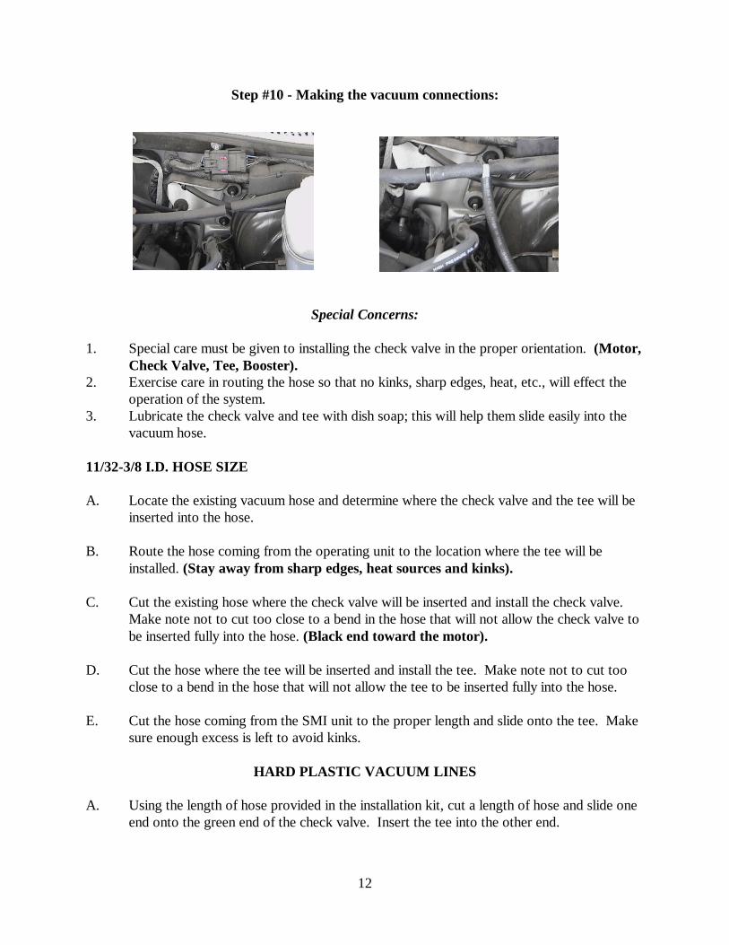
Step #10 - Making the vacuum connections:
Special Concerns:
1. Special care must be given to installing the check valve in the proper orientation. (Motor,Check Valve, Tee, Booster).
2. Exercise care in routing the hose so that no kinks, sharp edges, heat, etc., will effect theoperation of the system.
3. Lubricate the check valve and tee with dish soap; this will help them slide easily into thevacuum hose.
11/32-3/8 I.D. HOSE SIZE
A. Locate the existing vacuum hose and determine where the check valve and the tee will beinserted into the hose.
B. Route the hose coming from the operating unit to the location where the tee will beinstalled. (Stay away from sharp edges, heat sources and kinks).
C. Cut the existing hose where the check valve will be inserted and install the check valve. Make note not to cut too close to a bend in the hose that will not allow the check valve tobe inserted fully into the hose. (Black end toward the motor).
D. Cut the hose where the tee will be inserted and install the tee. Make note not to cut tooclose to a bend in the hose that will not allow the tee to be inserted fully into the hose.
E. Cut the hose coming from the SMI unit to the proper length and slide onto the tee. Makesure enough excess is left to avoid kinks.
HARD PLASTIC VACUUM LINES
A. Using the length of hose provided in the installation kit, cut a length of hose and slide oneend onto the green end of the check valve. Insert the tee into the other end.

13
B. Cut another length of hose and insert the open end of the tee into it. (The open end of thehose will slip over the smaller hard plastic tubing). Cut another length of hose and insertthe open (black end) of the check valve.
C. Cut out a portion of the existing hard plastic tubing and slip the open ends of the hoseover the plastic tubing. Make sure the black end of the check valve is toward themotor.
D. Put the enclosed clamps on the hose that the hard plastic tubing is inserted into.
E. Cut the hose coming from the SMI unit to the proper length and slide onto the tee. Makesure enough excess is left to avoid kinks.
5/8 I.D. VACUUM LINES
A. Using the length of hose provided in the installation kit, cut a length of hose and slide oneend onto the green end of the check valve. Insert the tee into the other end.
B. Cut another length of hose and insert the open (black) end of the tee. Slide the hoseadaptor into the other end.
C. Cut another length of hose and insert the open end of the tee into it. Slide the other hoseadaptor into the other end.
D. Cut out a portion of thee existing larger vacuum hose out and slip adaptor into the openends of the hose. Make sure the black end of the check valve is toward the motor.
E. Cut the hose coming from the SMI unit to the proper length and slide onto the tee. Makesure enough excess is left to avoid kinks.
Step #11 - Testing the install:
A. Push the brake pedal down. The green light on the transmitter will flicker. If not, checkthe 12 volts from the brake light switch connection and the ground connection, and verifythat the toggle switch is turned on. Next, plug the radio receiver in the power point of thetowed vehicle and apply the brakes. The “Red” light will come on as the brakes areapplied. Keep the brakes applied. After a few seconds a buzzer will sound.
B. When the toggle switch is turned on, the vacuum pump will run for 30 to 45 seconds andstop. The pump should not cycle more than 1 time in a minute period.
C. Remove the breakaway pin and observe the operation of the cylinder. Note the cableattached to the firewall. It should be as close to an inch above being straight with thecylinder as possible (see Step #6-B) When it is in this location, the cable will be straightwith the cylinder when the brake pedal is in the down position. Replace the breakaway pin

14
and make sure the brake released completely.
D. The vacuum pump will run continuously, and apply the brakes of the towed vehicle. Notethe flickering transmitter. As the pump runs, more brake effort is applied to the towedvehicle until the maximum effort is reached. Let the pump run for about 1 minute andreplace the breakaway pin. Verify that the brakes in the towed vehicle are fully released. Inspect the cable clamp and verify the cable has not slipped in the clamp.
E. Tape all electrical connections with a high quality electrical tape, and use cable ties tosecure the wires. Replace all the molding and kick plate.
Step #12 - Testing the install continued:Ready the towed for towing.
A. Place the receiver in the cockpit of the motor home in the line of sight. The receiver isbest located to the left of the steering wheel facing the driver. Do not anchor it at thistime, this may be a temporary location. Plug the radio receiver into the power outlet, (besure to attach the whip antenna) and it will be ready to receive signals from the transmitterin the towed vehicle. Remember, whenever the red light is on, THE BRAKES ON THETOWED VEHICLE ARE ENGAGED!
B. Pull the pin from the breakaway switch. (The dead plug with the short cable is to keepdirt and moisture from getting into the switch while driving the towed.) This will activatethe brakes in the towed vehicle and will turn the SMI Receiver light on in the coach. Check the receiver in the coach to confirm the red light is on. By this time the buzzer willbe on also. If the red light is not on, move the receiver to a location that will allow thelight to activate. Start the engine in the motor home and check the receiver. Start thegenerator and check the receiver. Replace the plug in the breakaway switch. The brakeswill release and the red light in the coach will go out.
C. Loosen the SENSITIVITY KNOB and raise it to the top of the slot. Have a partner holdthe coach brake pedal down. Tip the unit forward. The SMI unit will activate. The SMIunit will stay activated as long as the coach brakes are on, regardless of where you placethe SENSITIVITY KNOB. The SMI will not activate without the coach moving unlessthe unit is tipped up. This test simulates stopping inertia. When the coach brakes arereleased, the SMI will release the towed vehicles brake. REPEAT THIS TEST WITHTHE HEADLIGHTS OF THE COACH ON. (If the SMI unit does NOT release,diodes must be placed in the towed wiring.) It is critical that your installation passesboth of these tests. If not see number 4 of Trouble Shooting the SMI.
Step #13 - The vacuum:
A. The vacuum is factory set at about 12 inches. With the motor and the SMI unit turnedoff, pump the brake in the towed to deplete the vacuum in the brake booster.
15
B. Turn the SMI unit on. The pump will run until it reaches the pre-set vacuum setting. Manually depress the brake pedal again. The pump will run until it reaches the presetlevel.
.
Step #14 - Adjusting the G-FORCE controller:
A. Place the black knob of the G-Force controller in the center of the curvedslot. In this position, the brake should not activate, for diesel rigs, if an exhaust brake is inuse. For gas rigs, it will not activate when feathering the brakes, such as coming upon atraffic light or slowing for a rest area. For all rigs it will activate for a yellow-light stop.
B. If while stopping the red light is not on in the cockpit but you want the brake to be on inthe towed vehicle, choose a safe place to pull over and move the G-Force knob up about1/16th of an inch.
C. If while stopping the red light is on in the cockpit but is NOT wanted, then move the G-Force knob down about 1/16th of an inch.
D. After two or three stops, the “Sweet Spot” will be discovered. Tighten the knob of the G-Force controller and mark it with a pen. If the knob is ever moved, the “Sweet Spot” canalways be easily found.

16
Step #15 - The breakaway cable:
Loop the breakaway cable around the receiver and exchange the dead plug for the cable. Thelength of the cable should be long enough that it will not pull out on the tightest possible turnsmade in either direction. It should be short enough that it will pull out before the towed reachesthe end of the safety cables.
Trouble Shooting
We exercise great care in building and packaging your unit. All operating units are thoroughlybench tested before being shipped. We encourage you to contact our Help Line any time youhave questions about the installation or operation of your SMI Vacuum Assisted Brake.
VACUUM
1. Vacuum Pump will not shut off:
A. Check to see that the breakaway pin is secure!
B. Depending on the size of the brake booster, the vacuum pump may operate up to45 seconds any time the operating unit is being readied for use in the towedvehicle. Also, virtually every towed vehicle’s vacuum system leaks (some morethan others), and it is not unusual for the pump to cycle occasionally but shouldnot cycle more than once in a 5 minute period. If the vacuum does not hold,remove the quick disconnect from the black vacuum tube. Moisten your thumband place it over the male connector on the unit. If it does not hold, call the HelpLine. If it holds, the leak is in the connections under the hood or in the boosteritself. Check the connections and use hose clamps if necessary.
C. If the pump continues to cycle call the Help Line.
WIRING
1. Unit failed to operate when plugged in:Be sure the toggle switch is in the on position. Using a voltmeter or a test light, determineif there is 12VDC between the BROWN wire and the WHITE ground wire on the SMIplug. There should be 12VDC between these two wires at all times, when the switch ison. Check the fuse and the holder at the battery and the WHITE wire connection. Also,be sure you installed the 15-amp fuse in the fuse holder.
2. Unit failed to operate when the RV brakes were applied.A. Check Continuity to the ground from the WHITE wire at the PLUG. If not, re-
ground the WHITE wire to the frame of the towed vehicle.
B. With the RV brakes applied check for 12 volts between the SMI YELLOW wire
17
and the SMI WHITE wire. Also check for 12 volts on the GREEN wire to theSMI WHITE wire. If no voltage is present, check the scotch lock connections tothe towed vehicle towwiring. Remember the 12 volts for this is coming from the coach. Check to seethat the coach is grounded properly to the car in the tow wiring.
C. Plug the SMI unit back in and apply the RV brakes with the tow wiring connected. Tip the unit forward. If you checked the voltage and the unit still does notoperate, call the Help Line.
3. Breakaway failed to operate the brakes.Remove the breakaway plug from the front of the towed vehicle, test for 12VDC betweenthe BLUE wire and the WHITE ground wire. There should be a 12VDC at that time, andONLY then. If not, check continuity to ground with the WHITE wire. Check theconnection at the battery and the fuse. Check the connection of the BLUE wire.
4. Unit operated but did not release the brakes.This is commonly referred to as a “feedback.” To correct the problem you need to adddiodes to the tow wiring. They must be placed between the rear of the towed vehicle andthe SMI connection. Their location is not critical just so the SMI connection is “closest”to the motor home. Diodes are available at most any towing center or by call the HelpLine (all you pay is the shipping).
NOTEIf diodes are not present in the tow wiring there will most likely be a feedback to the SMI unitbecause we are applying the brake pedal. When the SMI activates from the brake signal in thecoach, the towed vehicle brakes will not release if the diodes are not placed correctly. Followthe testing procedures completely to determine if the diodes are correct. See the section ontrouble shooting the SMI.
5. Radio Receiver does not light up.A. First verify the green LED on the transmitter is flickering with the towed vehicle
brakes applied. If not, check the ground connection, verify that the toggle switchis turned on, and verify 12 volts on the red wire with the towed vehicles brakesapplied. If there is not, check your connection at the brake switch. If it flickers,plug the receiver in the cigarette adaptor of the towed vehicle and push the towedvehicle brake pedal. The receiver light should come on. If
not, call the Help Line. A glass mount antenna is available shouldyou experience any receiver problems. Radio reception is critical to the safeoperation of the SMI Stay-IN-Play brake system.
B. If it works in the towed vehicle, plug the receiver into the coach power point andmove it around to find the best location for your coach. Most likely there isinterference that is causing the radio to drop the signal. Left of the driver is

18
generally the best location. If you still have trouble, call the Help Line.
What now?If the voltage is correct and the unit still does not operate properly, you will need technicalassistance from SMI Manufacturing, Inc. Call us at 1-800-893-3763, or e-mail [email protected]

19

20
This page is intentionally left blank

21

22