Embed Size (px)
Citation preview
1NOTE: DIAGRAMS & ILLUSTRATIONS NOT TO SCALE.
INSTALLATIONINSTRUCTIONS
DIRECT VENT DELUXEBDM35 AND BDM35P
VENTED GAS FIREPLACE HEATERS - DIRECT VENT MODELSP/N 800,017M REV. E 08/2002
RETAIN THESE INSTRUCTIONSFOR FUTURE REFERENCE
FOR YOUR SAFETY: Do not store or use gasolineor other flammable vapors or liquids in the vicin-ity of this or any other appliance.
FOR YOUR SAFETY: What to do if you smell gas:
• DO NOT light any appliance.• DO NOT touch any electrical switches.• DO NOT use any phone in your building.• Immediately call your gas supplier from a
neighbor’s phone. Follow your gas suppliersinstructions.
• If your gas supplier cannot be reached, call thefire department.
Installation and service must be performed by aqualified installer, service agency or the gassupplier.
MODELS
WARNING: IF THE INFORMATION IN THIS MANUALIS NOT FOLLOWED EXACTLY, A FIRE OR EXPLO-SION MAY RESULT CAUSING PROPERTY DAM-AGE, PERSONAL INJURY OR LOSS OF LIFE.
WH Report No. J20006711
Millivolt ModelsBDM35
BDM35P
This appliance may be installed as an OEM in-stallation in a manufactured home (USA only) ormobile home and must be installed in accor-dance with the manufacturer's instructions andthe manufactured home construction and safetystandard, Title 24 CPF, Part 3280 or Standard forInstallation in Mobile Homes, CAN/CSA Z240MH. This appliance is only for use with thetype(s) of gas indicated on the rating plate. Aconversion kit is supplied with the appliance.
POUR VOTRE SÉCURITÉ: Ne pas entreposer ni utiliserd'essence ni d'autre vapeurs ou liquides inflammablesdans le voisinage de cet appareil ou de tout autreappareil.
POUR VOTRE SÉCURITÉ: Que faire si vous sentez uneodeur de gaz:
• Ne pas tenter d'allumer d'appareil.• Ne touchez à aucun interrupteur. Ne pas vous servir
des téléphones se trouvant dans le batiment oùvous vous trouvez.
• Evacuez la piéce, le bâtiment ou la zone.• Appelez immédiatement votre fournisseur de gaz
depuis un voisin. Suivez les instructions dufournisseur.
• Si vous ne pouvez rejoindre le fournisseur de gaz,appelez le service dos incendies.
L'installation et service doit être exécuté par un qualifiéinstalleur, agence de service ou le fournisseur de gaz.
AVERTISSEMENT: ASSUREZ-VOUS DE BIEN SUIVRELES INSTRUCTIONS DONNÉ DANS CETTE NOTICE POURRÉDUIRE AU MINIMUM LE RISQUE D'INCENDIE OUPOUR ÉVITER TOUT DOMMAGE MATÉRIEL, TOUTEBLESSURE OU LA MORT.
2 NOTE: DIAGRAMS & ILLUSTRATIONS NOT TO SCALE.
Figure 1
TABLE OF CONTENTS
Packaging ........................................ page 2
Introduction ..................................... page 2
General Information ......................... page 2
Location .......................................... page 4
Appliance and Vent Clearances ....... page 4
Vent Termination Clearances ........... page 5
Typical Installation Sequence .......... page 5
Detailed Installation Steps ............... page 5
Step 1. Framing ............................. page 5
Step 2. Routing Gas Line ............... page 5
Fireplace Specifications ................... page 8
Step 3. Install the Venting System . page 9
Vertical Termination Systems .......... page 10
Vent Section Length Chart ............... page 10
Vertical Vent Tables and Figures ...... page 13
Horizontal Termination System ........ page 15
Horizontal Vent Tables and Figures . page 17
Venting Using Flexible Vent Pipe ..... page 20
Step 4. Millivolt Wiring .................. page 21
Step 5. Blower Wiring .................... page 21
Step 6. Connecting Gas Line and Checking
Gas Type ............................ page 21
Step 7. Installing Logs ................... page 22
Step 8. Checking Unit Operation ..... page 22
Step 9. Installing Glass Door ......... page 22
Step 10. Burner Adjustments ........... page 23
Step 11. Hood Installation ............... page 23
Finishing Requirements ................... page 23
Cold Climate Insulation .................... page 24
Installation Accessories ................... page 24
Gas Conversion Kits .................. page 26
PACKAGING
The assembled vented gas fireplace heater ispackaged with:
1 - one log set located in firebox area.2 - one envelope containing the literature
package which consists of the homeowner'smanual, installation instructions, log setsupplement and warranty; envelope is lo-cated in the control area.
3 - one vent restrictor to be applied as shown onpage 9; restrictor is taped to the envelope.
4 - one hood located behind the top panel.5 - one bag of decorative volcanic stone lo-
cated in the control area.6 - one bag of glowing embers located in the
control area.7 -one gas conversion kit located in the
control area.
INTRODUCTION
This vented gas fireplace heater is a sealedcombustion, air circulating gas fireplace de-signed for residential applications. This appli-ance must be installed with the Secure Vent™and /or Secure Flex™ vent systems routed tothe outside atmosphere.
These millivolt appliances are designed to oper-ate on natural or propane gas. For the BDM35fireplace, a natural gas to propane gas conver-sion kit is supplied. For the BDM35P fireplace,a propane gas to natural gas conversion kit issupplied. Conversion instructions are providedwith both kits, and on page 26 of this manual.A millivolt gas control valve with piezo ignitionsystem provides safe, efficient operation. Externalelectrical power is required to operate the factory-installed blower in this unit.
These appliances comply with National SafetyStandards and are tested and listed by WarnockHersey (Report No. J20006711) to ANSIZ21.88-2000 (in Canada, CSA-2.33-2000), andCAN/CGA-2.17-M91 in both USA and Canada,as vented gas fireplace heaters.
These appliances are listed by Warnock Herseyfor installation in bedrooms and mobile homes.
Installation must conform to local codes. In theabsence of local codes, installation must com-ply with the current National Fuel Gas Code,ANSI Z223.1. (In Canada, the current CAN-1B149 installation code.) Electrical wiring mustcomply with the National Electrical Code ANSI/NFPA 70 - (latest edition). (In Canada, thecurrent CSA C22-1 Canadian Electrical Code.)
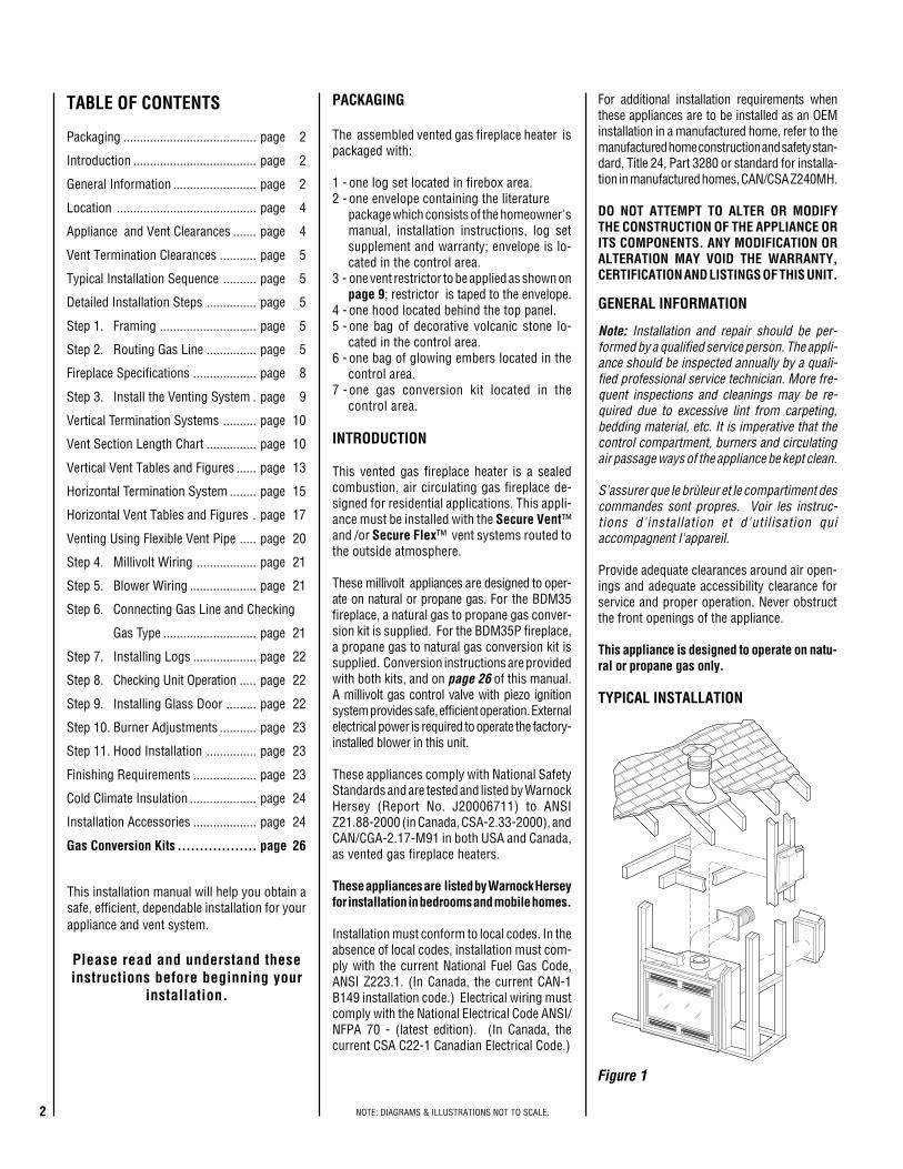
TYPICAL INSTALLATION
For additional installation requirements whenthese appliances are to be installed as an OEMinstallation in a manufactured home, refer to themanufactured home construction and safety stan-dard, Title 24, Part 3280 or standard for installa-tion in manufactured homes, CAN/CSA Z240MH.
DO NOT ATTEMPT TO ALTER OR MODIFYTHE CONSTRUCTION OF THE APPLIANCE ORITS COMPONENTS. ANY MODIFICATION ORALTERATION MAY VOID THE WARRANTY,CERTIFICATION AND LISTINGS OF THIS UNIT.
GENERAL INFORMATION
This installation manual will help you obtain asafe, efficient, dependable installation for yourappliance and vent system.
Please read and understand theseinstructions before beginning your
installation.
Note: Installation and repair should be per-formed by a qualified service person. The appli-ance should be inspected annually by a quali-fied professional service technician. More fre-quent inspections and cleanings may be re-quired due to excessive lint from carpeting,bedding material, etc. It is imperative that thecontrol compartment, burners and circulatingair passage ways of the appliance be kept clean.
S'assurer que le brùleur et le compartiment descommandes sont propres. Voir les instruc-tions d'installation et d'utilisation quiaccompagnent l'appareil.
Provide adequate clearances around air open-ings and adequate accessibility clearance forservice and proper operation. Never obstructthe front openings of the appliance.
This appliance is designed to operate on natu-ral or propane gas only.
3NOTE: DIAGRAMS & ILLUSTRATIONS NOT TO SCALE.
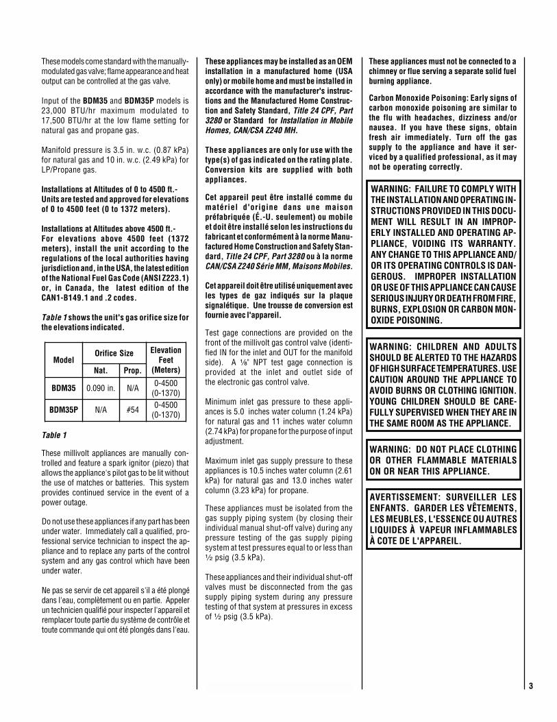
ledoMeziSecifirO noitavelE
teeF)sreteM(.taN .porP
53MDB .ni090.0 A/N 0054-0)0731-0(
P53MDB A/N 45# 0054-0)0731-0(
Table 1
These models come standard with the manually-modulated gas valve; flame appearance and heatoutput can be controlled at the gas valve.
Input of the BDM35 and BDM35P models is23,000 BTU/hr maximum modulated to17,500 BTU/hr at the low flame setting fornatural gas and propane gas.
Manifold pressure is 3.5 in. w.c. (0.87 kPa)for natural gas and 10 in. w.c. (2.49 kPa) forLP/Propane gas.
Installations at Altitudes of 0 to 4500 ft.-Units are tested and approved for elevationsof 0 to 4500 feet (0 to 1372 meters).
Installations at Altitudes above 4500 ft.-For elevations above 4500 feet (1372meters), install the unit according to theregulations of the local authorities havingjurisdiction and, in the USA, the latest editionof the National Fuel Gas Code (ANSI Z223.1)or, in Canada, the latest edition of theCAN1-B149.1 and .2 codes.
Table 1 shows the unit's gas orifice size forthe elevations indicated.
Test gage connections are provided on thefront of the millivolt gas control valve (identi-fied IN for the inlet and OUT for the manifoldside). A ¹⁄₈" NPT test gage connection isprovided at the inlet and outlet side ofthe electronic gas control valve.
Minimum inlet gas pressure to these appli-ances is 5.0 inches water column (1.24 kPa)for natural gas and 11 inches water column(2.74 kPa) for propane for the purpose of inputadjustment.
Maximum inlet gas supply pressure to theseappliances is 10.5 inches water column (2.61kPa) for natural gas and 13.0 inches watercolumn (3.23 kPa) for propane.
Do not use these appliances if any part has beenunder water. Immediately call a qualified, pro-fessional service technician to inspect the ap-pliance and to replace any parts of the controlsystem and any gas control which have beenunder water.
Ne pas se servir de cet appareil s'il a été plongédans l'eau, complètement ou en partie. Appelerun technicien qualifié pour inspecter l'appareil etremplacer toute partie du système de contrôle ettoute commande qui ont été plongés dans l'eau.
These millivolt appliances are manually con-trolled and feature a spark ignitor (piezo) thatallows the appliance's pilot gas to be lit withoutthe use of matches or batteries. This systemprovides continued service in the event of apower outage.
Carbon Monoxide Poisoning: Early signs ofcarbon monoxide poisoning are similar tothe flu with headaches, dizziness and/ornausea. If you have these signs, obtainfresh air immediately. Turn off the gassupply to the appliance and have it ser-viced by a qualified professional, as it maynot be operating correctly.
WARNING: DO NOT PLACE CLOTHINGOR OTHER FLAMMABLE MATERIALSON OR NEAR THIS APPLIANCE.
WARNING: CHILDREN AND ADULTSSHOULD BE ALERTED TO THE HAZARDSOF HIGH SURFACE TEMPERATURES. USECAUTION AROUND THE APPLIANCE TOAVOID BURNS OR CLOTHING IGNITION.YOUNG CHILDREN SHOULD BE CARE-FULLY SUPERVISED WHEN THEY ARE INTHE SAME ROOM AS THE APPLIANCE.
AVERTISSEMENT: SURVEILLER LESENFANTS. GARDER LES VÊTEMENTS,LES MEUBLES, L'ESSENCE OU AUTRESLIQUIDES À VAPEUR INFLAMMABLESÀ COTE DE L'APPAREIL.
These appliances must be isolated from thegas supply piping system (by closing theirindividual manual shut-off valve) during anypressure testing of the gas supply pipingsystem at test pressures equal to or less than¹⁄₂ psig (3.5 kPa).
These appliances and their individual shut-offvalves must be disconnected from the gassupply piping system during any pressuretesting of that system at pressures in excessof ¹⁄₂ psig (3.5 kPa).
WARNING: FAILURE TO COMPLY WITHTHE INSTALLATION AND OPERATING IN-STRUCTIONS PROVIDED IN THIS DOCU-MENT WILL RESULT IN AN IMPROP-ERLY INSTALLED AND OPERATING AP-PLIANCE, VOIDING ITS WARRANTY.ANY CHANGE TO THIS APPLIANCE AND/OR ITS OPERATING CONTROLS IS DAN-GEROUS. IMPROPER INSTALLATIONOR USE OF THIS APPLIANCE CAN CAUSESERIOUS INJURY OR DEATH FROM FIRE,BURNS, EXPLOSION OR CARBON MON-OXIDE POISONING.
These appliances may be installed as an OEMinstallation in a manufactured home (USAonly) or mobile home and must be installed inaccordance with the manufacturer's instruc-tions and the Manufactured Home Construc-tion and Safety Standard, Title 24 CPF, Part3280 or Standard for Installation in MobileHomes, CAN/CSA Z240 MH.
These appliances are only for use with thetype(s) of gas indicated on the rating plate.Conversion kits are supplied with bothappliances.
Cet appareil peut être installé comme dumatériel d'origine dans une maisonpréfabriquée (É.-U. seulement) ou mobileet doit être installé selon les instructions dufabricant et conformément à la norme Manu-factured Home Construction and Safety Stan-dard, Title 24 CPF, Part 3280 ou à la normeCAN/CSA Z240 Série MM, Maisons Mobiles.
Cet appareil doit être utilisé uniquement avecles types de gaz indiqués sur la plaquesignalétique. Une trousse de conversion estfournie avec l'appareil.
These appliances must not be connected to achimney or flue serving a separate solid fuelburning appliance.
4 NOTE: DIAGRAMS & ILLUSTRATIONS NOT TO SCALE.
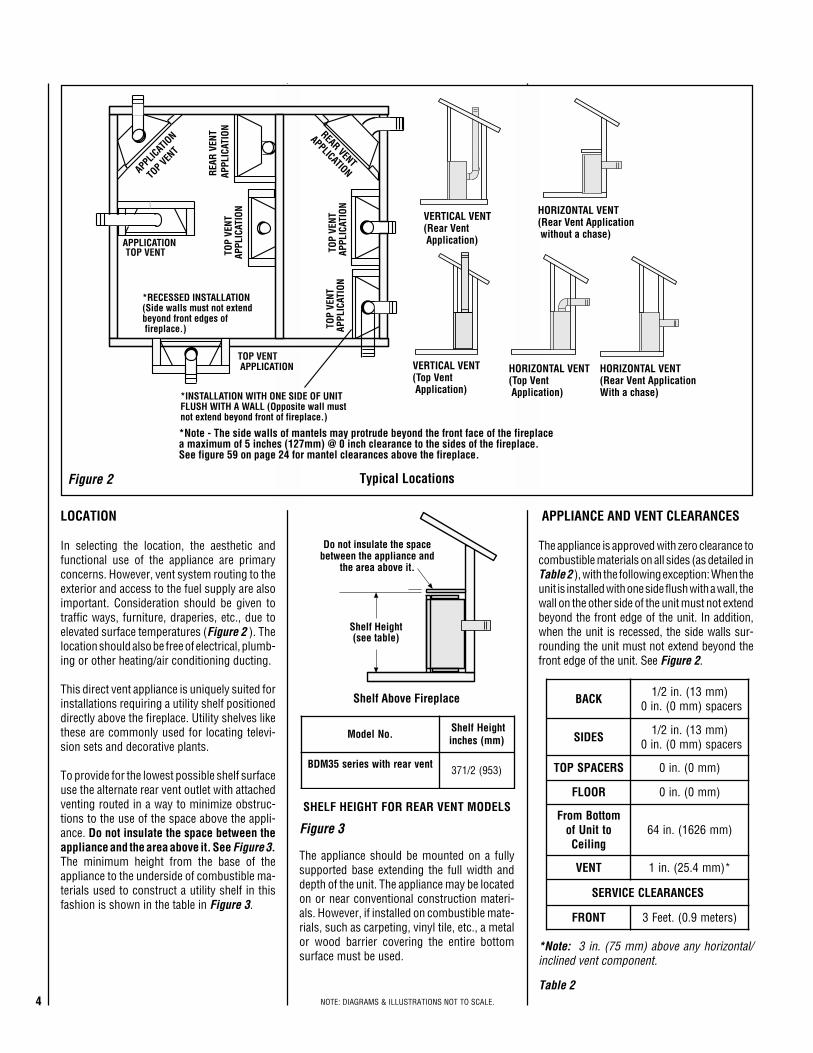
Shelf Above Fireplace
Do not insulate the spacebetween the appliance and
the area above it.
Shelf Height(see table)
KCAB )mm31(.ni2/1srecaps)mm0(.ni0
SEDIS )mm31(.ni2/1srecaps)mm0(.ni0
SRECAPSPOT )mm0(.ni0
ROOLF )mm0(.ni0
mottoBmorFottinUfo
gnilieC)mm6261(.ni46
TNEV *)mm4.52(.ni1
SECNARAELCECIVRES
TNORF )sretem9.0(.teeF3
.oNledoM thgieHflehS)mm(sehcni
tnevraerhtiwseires53MDB 3 2/17 )359(
TOP VENT
TOP VEN
T
*INSTALLATION WITH ONE SIDE OF UNITFLUSH WITH A WALL (Opposite wall mustnot extend beyond front of fireplace.)
*RECESSED INSTALLATION(Side walls must not extendbeyond front edges of fireplace.)
APPLICATION
APPLICAT
ION REAR VENT
APPLICATIONREAR
VEN
T A
PPLI
CATI
ON
TOP VENT APPLICATION
TOP
VENT
APP
LICA
TION
TOP
VENT
APP
LICA
TION
TOP
VENT
APP
LICA
TION
VERTICAL VENT(Top Vent Application)
HORIZONTAL VENT(Rear Vent ApplicationWith a chase)
HORIZONTAL VENT(Rear Vent Application without a chase)
HORIZONTAL VENT(Top Vent Application)
VERTICAL VENT(Rear Vent Application)
*Note - The side walls of mantels may protrude beyond the front face of the fireplacea maximum of 5 inches (127mm) @ 0 inch clearance to the sides of the fireplace.See figure 59 on page 24 for mantel clearances above the fireplace.
Figure 2
Figure 3
*Note: 3 in. (75 mm) above any horizontal/inclined vent component.
Table 2
LOCATION
In selecting the location, the aesthetic andfunctional use of the appliance are primaryconcerns. However, vent system routing to theexterior and access to the fuel supply are alsoimportant. Consideration should be given totraffic ways, furniture, draperies, etc., due toelevated surface temperatures (Figure 2 ). Thelocation should also be free of electrical, plumb-ing or other heating/air conditioning ducting.
This direct vent appliance is uniquely suited forinstallations requiring a utility shelf positioneddirectly above the fireplace. Utility shelves likethese are commonly used for locating televi-sion sets and decorative plants.
To provide for the lowest possible shelf surfaceuse the alternate rear vent outlet with attachedventing routed in a way to minimize obstruc-tions to the use of the space above the appli-ance. Do not insulate the space between theappliance and the area above it. See Figure 3.The minimum height from the base of theappliance to the underside of combustible ma-terials used to construct a utility shelf in thisfashion is shown in the table in Figure 3.
APPLIANCE AND VENT CLEARANCES
The appliance is approved with zero clearance tocombustible materials on all sides (as detailed inTable 2 ), with the following exception: When theunit is installed with one side flush with a wall, thewall on the other side of the unit must not extendbeyond the front edge of the unit. In addition,when the unit is recessed, the side walls sur-rounding the unit must not extend beyond thefront edge of the unit. See Figure 2.
Typical Locations
The appliance should be mounted on a fullysupported base extending the full width anddepth of the unit. The appliance may be locatedon or near conventional construction materi-als. However, if installed on combustible mate-rials, such as carpeting, vinyl tile, etc., a metalor wood barrier covering the entire bottomsurface must be used.
SHELF HEIGHT FOR REAR VENT MODELS
5NOTE: DIAGRAMS & ILLUSTRATIONS NOT TO SCALE.
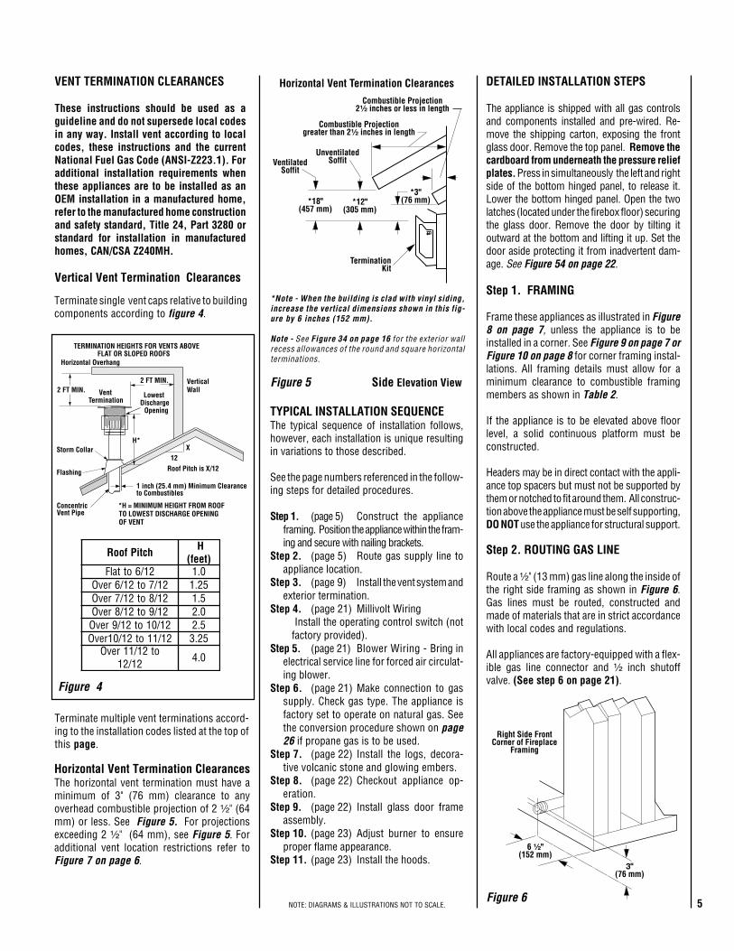
12X
Roof Pitch is X/12
2 FT MIN.2 FT MIN.
LowestDischarge
Opening
H*
*H = MINIMUM HEIGHT FROM ROOFTO LOWEST DISCHARGE OPENINGOF VENT
TERMINATION HEIGHTS FOR VENTS ABOVEFLAT OR SLOPED ROOFS
Horizontal Overhang
VerticalWallVent
Termination
Storm Collar
ConcentricVent Pipe
Flashing
1 inch (25.4 mm) Minimum Clearanceto Combustibles
hctiPfooR H)teef(
21/6ottalF 0.121/7ot21/6revO 52.121/8ot21/7revO 5.121/9ot21/8revO 0.221/01ot21/9revO 5.221/11ot21/01revO 52.3
ot21/11revO21/21 0.4
*3"(76 mm)*12"
(305 mm)
TerminationKit
Combustible Projectiongreater than 2¹⁄₂ inches in length
Horizontal Vent Termination ClearancesCombustible Projection
2¹⁄₂ inches or less in length
*18"(457 mm)
VentilatedSoffit
UnventilatedSoffit
6 ¹⁄₂"(152 mm)
Right Side FrontCorner of Fireplace
Framing
3"(76 mm)
Figure 4
Figure 5 Side Elevation View
Figure 6
Horizontal Vent Termination ClearancesThe horizontal vent termination must have aminimum of 3" (76 mm) clearance to anyoverhead combustible projection of 2 ¹⁄₂" (64mm) or less. See Figure 5. For projectionsexceeding 2 ¹⁄₂" (64 mm), see Figure 5. Foradditional vent location restrictions refer toFigure 7 on page 6.
Terminate multiple vent terminations accord-ing to the installation codes listed at the top ofthis page.
Terminate single vent caps relative to buildingcomponents according to figure 4.
TYPICAL INSTALLATION SEQUENCEThe typical sequence of installation follows,however, each installation is unique resultingin variations to those described.
See the page numbers referenced in the follow-ing steps for detailed procedures.
Step 1. (page 5) Construct the applianceframing. Position the appliance within the fram-ing and secure with nailing brackets.
Step 2. (page 5) Route gas supply line toappliance location.
Step 3. (page 9) Install the vent system andexterior termination.
Step 4. (page 21) Millivolt Wiring Install the operating control switch (notfactory provided).
Step 5. (page 21) Blower Wiring - Bring inelectrical service line for forced air circulat-ing blower.
Step 6. (page 21) Make connection to gassupply. Check gas type. The appliance isfactory set to operate on natural gas. Seethe conversion procedure shown on page26 if propane gas is to be used.
Step 7. (page 22) Install the logs, decora-tive volcanic stone and glowing embers.
Step 8. (page 22) Checkout appliance op-eration.
Step 9. (page 22) Install glass door frameassembly.
Step 10. (page 23) Adjust burner to ensureproper flame appearance.
Step 11. (page 23) Install the hoods.
DETAILED INSTALLATION STEPS
The appliance is shipped with all gas controlsand components installed and pre-wired. Re-move the shipping carton, exposing the frontglass door. Remove the top panel. Remove thecardboard from underneath the pressure reliefplates. Press in simultaneously the left and rightside of the bottom hinged panel, to release it.Lower the bottom hinged panel. Open the twolatches (located under the firebox floor) securingthe glass door. Remove the door by tilting itoutward at the bottom and lifting it up. Set thedoor aside protecting it from inadvertent dam-age. See Figure 54 on page 22.
Step 1. FRAMING
Frame these appliances as illustrated in Figure8 on page 7, unless the appliance is to beinstalled in a corner. See Figure 9 on page 7 orFigure 10 on page 8 for corner framing instal-lations. All framing details must allow for aminimum clearance to combustible framingmembers as shown in Table 2.
If the appliance is to be elevated above floorlevel, a solid continuous platform must beconstructed.
Headers may be in direct contact with the appli-ance top spacers but must not be supported bythem or notched to fit around them. All construc-tion above the appliance must be self supporting,DO NOT use the appliance for structural support.
Step 2. ROUTING GAS LINE
Route a ¹⁄₂" (13 mm) gas line along the inside ofthe right side framing as shown in Figure 6.Gas lines must be routed, constructed andmade of materials that are in strict accordancewith local codes and regulations.
All appliances are factory-equipped with a flex-ible gas line connector and ¹⁄₂ inch shutoffvalve. (See step 6 on page 21).
Vertical Vent Termination Clearances
VENT TERMINATION CLEARANCES
These instructions should be used as aguideline and do not supersede local codesin any way. Install vent according to localcodes, these instructions and the currentNational Fuel Gas Code (ANSI-Z223.1). Foradditional installation requirements whenthese appliances are to be installed as anOEM installation in a manufactured home,refer to the manufactured home constructionand safety standard, Title 24, Part 3280 orstandard for installation in manufacturedhomes, CAN/CSA Z240MH.
*Note - When the building is clad with vinyl siding,increase the vertical dimensions shown in this fig-ure by 6 inches (152 mm).
Note - See Figure 34 on page 16 for the exterior wallrecess allowances of the round and square horizontalterminations.
6 NOTE: DIAGRAMS & ILLUSTRATIONS NOT TO SCALE.
Figure 7
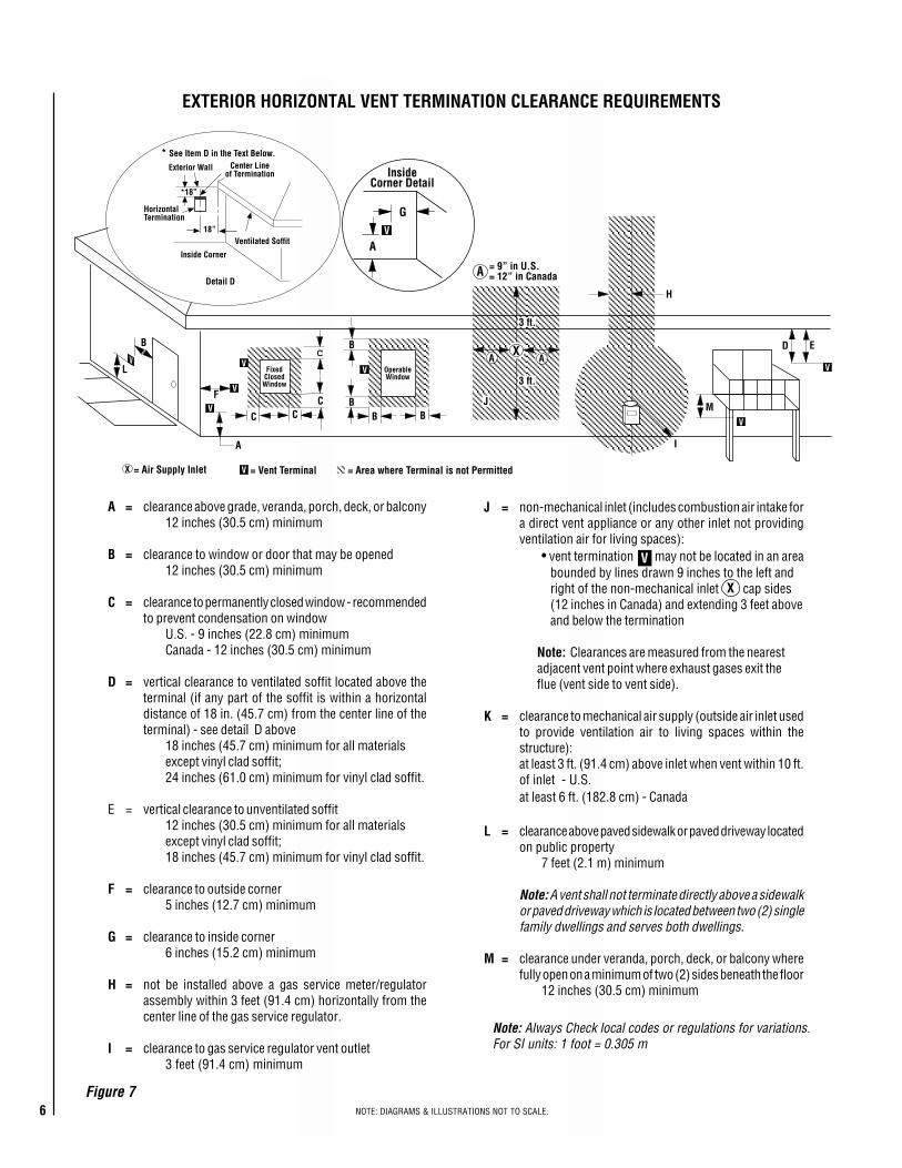
A = clearance above grade, veranda, porch, deck, or balcony12 inches (30.5 cm) minimum
B = clearance to window or door that may be opened12 inches (30.5 cm) minimum
C = clearance to permanently closed window - recommendedto prevent condensation on window
U.S. - 9 inches (22.8 cm) minimumCanada - 12 inches (30.5 cm) minimum
D = vertical clearance to ventilated soffit located above theterminal (if any part of the soffit is within a horizontaldistance of 18 in. (45.7 cm) from the center line of theterminal) - see detail D above
18 inches (45.7 cm) minimum for all materialsexcept vinyl clad soffit;24 inches (61.0 cm) minimum for vinyl clad soffit.
E = vertical clearance to unventilated soffit12 inches (30.5 cm) minimum for all materialsexcept vinyl clad soffit;18 inches (45.7 cm) minimum for vinyl clad soffit.
F = clearance to outside corner5 inches (12.7 cm) minimum
G = clearance to inside corner6 inches (15.2 cm) minimum
H = not be installed above a gas service meter/regulatorassembly within 3 feet (91.4 cm) horizontally from thecenter line of the gas service regulator.
I = clearance to gas service regulator vent outlet3 feet (91.4 cm) minimum
J = non-mechanical inlet (includes combustion air intake fora direct vent appliance or any other inlet not providingventilation air for living spaces):
• vent termination may not be located in an areabounded by lines drawn 9 inches to the left andright of the non-mechanical inlet cap sides(12 inches in Canada) and extending 3 feet aboveand below the termination
Note: Clearances are measured from the nearestadjacent vent point where exhaust gases exit theflue (vent side to vent side).
K = clearance to mechanical air supply (outside air inlet usedto provide ventilation air to living spaces within thestructure):at least 3 ft. (91.4 cm) above inlet when vent within 10 ft.of inlet - U.S.at least 6 ft. (182.8 cm) - Canada
L = clearance above paved sidewalk or paved driveway locatedon public property
7 feet (2.1 m) minimum
Note: A vent shall not terminate directly above a sidewalkor paved driveway which is located between two (2) singlefamily dwellings and serves both dwellings.
M = clearance under veranda, porch, deck, or balcony wherefully open on a minimum of two (2) sides beneath the floor
12 inches (30.5 cm) minimum
X
V
Note: Always Check local codes or regulations for variations.For SI units: 1 foot = 0.305 m
EXTERIOR HORIZONTAL VENT TERMINATION CLEARANCE REQUIREMENTS
V
VV
V
V
F
C
FixedClosed
Window
OperableWindow
B
B
A
B
H
M
I
= Vent Terminal = Area where Terminal is not Permitted= Air Supply InletX V
D
V
3 ft.
3 ft.
A A
A = 9” in U.S.= 12” in Canada
VL
B
J
X E
V
A
G
InsideCorner Detail
*18”
Ventilated Soffit
HorizontalTermination
Detail D
Exterior Wall Center Lineof Termination
18”
Inside Corner
BC
C
C
* See Item D in the Text Below.
7NOTE: DIAGRAMS & ILLUSTRATIONS NOT TO SCALE.
41¹⁄₄
(1048)
37¹⁄₂
(953)
*41⁹⁄₁₆
(1056)
7(178)5¹⁄₈
12¹⁄₈(308)
10 ¹⁄₂(267)
*24⁷⁄₃₂
(615)
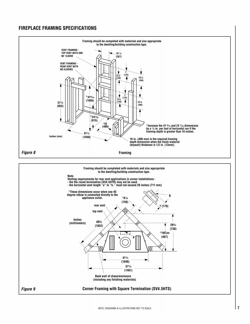
VENT FRAMING -TOP VENT WITH ONE90° ELBOW
VENT FRAMING -REAR VENT WITHNO ELBOWS
Framing should be completed with materials and size appropriateto the dwelling/building construction type.
Inches (mm)
*16(406)
(130)
16 in. (406 mm) is the required framingdepth dimension when the finish material(drywall) thickness is 1/2 in. (13mm).
*Increase the 41 ⁹⁄₁₆ and 24 ⁷⁄₃₂ dimensionsby a ¹⁄₄ in. per foot of horizontal run if theframing depth is greater than 16 inches.
7(178)
5¹⁄₈(130) 12¹⁄₈
(308)
Back wall of chase/enclosure(including any finishing materials)
a
7 (178)
b
Note-Venting requirements for rear vent applications in corner installations -- the the round termination (SV4.5HTR) may not be used- the horizontal vent length “a” to “b,” must not exceed 28 inches (711 mm)
Inches(millimeters)
*These dimensions occur when one 45degree elbow is connected directly to the
appliance collar.
41¹⁄₄
(1048)
40⁵⁄₈
(1032)
top vent
rear vent
*19C\zn(487)
28³⁄₄
(730)
57¹⁄₂
(1461)
*6¹⁄₈
(156)
Framing should be completed with materials and size appropriateto the dwelling/building construction type.
Figure 9
Figure 8
Corner Framing with Square Termination (SV4.5HTS)
FIREPLACE FRAMING SPECIFICATIONS
Framing
8 NOTE: DIAGRAMS & ILLUSTRATIONS NOT TO SCALE.
40 ⁵⁄₈(1032)
Back wall of chase/enclosure(including any finishing materials)
a
8 ³⁄₁₆ (208)
b
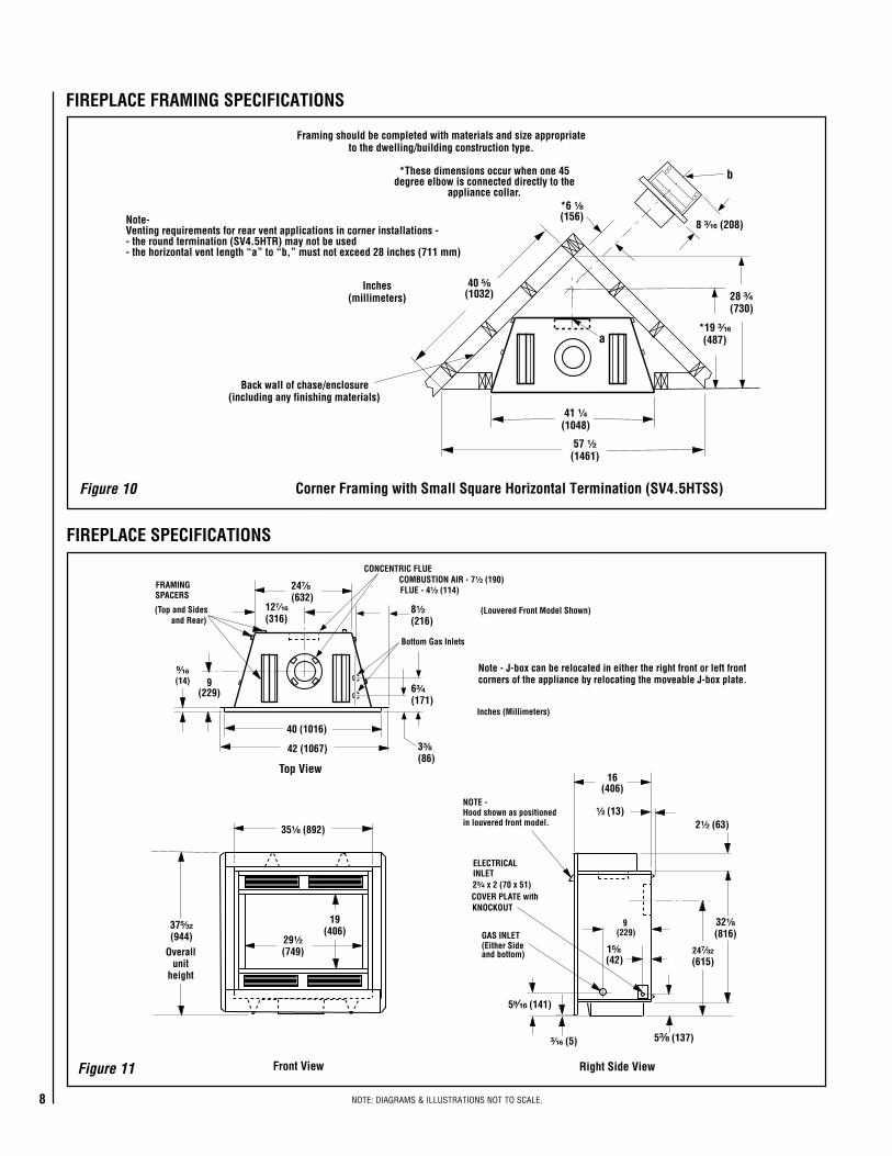
Note-Venting requirements for rear vent applications in corner installations -- the round termination (SV4.5HTR) may not be used- the horizontal vent length “a” to “b,” must not exceed 28 inches (711 mm)
*19 ³⁄₁₆(487)
Inches(millimeters)
*These dimensions occur when one 45degree elbow is connected directly to the
appliance collar.*6 ¹⁄₈(156)
28 ³⁄₄(730)
41 ¹⁄₄(1048)
57 ¹⁄₂(1461)
Framing should be completed with materials and size appropriateto the dwelling/building construction type.
9(229)
24⁷⁄₈
(632)
40 (1016)
32¹⁄₈
(816)29¹⁄₂
(749)
19(406)
24⁷⁄₃₂
(615)
16(406)
¹⁄₂ (13)
1⁵⁄₈(42)
9(229)
5⁹⁄₁₆ (141)
Top View
NOTE -Hood shown as positionedin louvered front model.
CONCENTRIC FLUE
FLUE - 4¹⁄₂ (114)COMBUSTION AIR - 7¹⁄₂ (190)
FRAMINGSPACERS
(Top and Sidesand Rear)
GAS INLET(Either Sideand bottom)
Front View
2¹⁄₂ (63)
(Louvered Front Model Shown)
ELECTRICALINLET2³⁄₄ x 2 (70 x 51)COVER PLATE withKNOCKOUT
Right Side View
⁹⁄₁₆(14)
42 (1067)
35¹⁄₈ (892)
12⁷⁄₁₆
(316)
Inches (Millimeters)
37⁵⁄₃₂
(944)
³⁄₁₆ (5)
Overallunit
height
Note - J-box can be relocated in either the right front or left frontcorners of the appliance by relocating the moveable J-box plate.
5³⁄₈ (137)
Bottom Gas Inlets
8¹⁄₂
(216)
6³⁄₄
(171)
3³⁄₈
(86)
Figure 11
Figure 10
FIREPLACE SPECIFICATIONS
FIREPLACE FRAMING SPECIFICATIONS
Corner Framing with Small Square Horizontal Termination (SV4.5HTSS)
9NOTE: DIAGRAMS & ILLUSTRATIONS NOT TO SCALE.
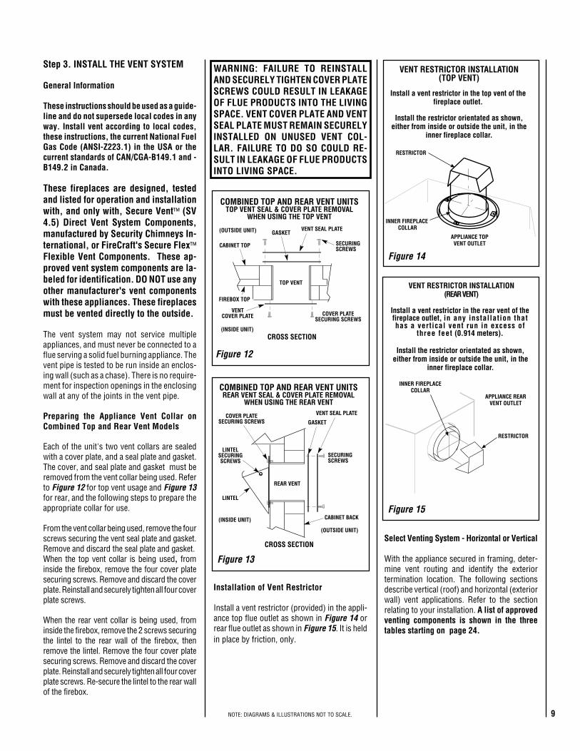
Figure 14
Figure 15
Install a vent restrictor in the top vent of thefireplace outlet.
RESTRICTOR
APPLIANCE TOPVENT OUTLET
VENT RESTRICTOR INSTALLATION(TOP VENT)
Install the restrictor orientated as shown,either from inside or outside the unit, in the
inner fireplace collar.
INNER FIREPLACE COLLAR
RESTRICTOR
APPLIANCE REARVENT OUTLET
Install a vent restrictor in the rear vent of thefireplace outlet, in any installation thathas a vertical vent run in excess of
three feet (0.914 meters).
VENT RESTRICTOR INSTALLATION(REAR VENT)
INNER FIREPLACECOLLAR
Install the restrictor orientated as shown,either from inside or outside the unit, in the
inner fireplace collar.
VENT SEAL PLATE
GASKET
SECURINGSCREWS
CROSS SECTION
LINTELSECURINGSCREWS
LINTEL
REAR VENT
COVER PLATESECURING SCREWS
COMBINED TOP AND REAR VENT UNITSREAR VENT SEAL & COVER PLATE REMOVAL
WHEN USING THE REAR VENT
CABINET BACK(INSIDE UNIT)
(OUTSIDE UNIT)
VENT SEAL PLATEGASKET
FIREBOX TOP
CABINET TOP SECURINGSCREWS
VENTCOVER PLATE
TOP VENT
COMBINED TOP AND REAR VENT UNITSTOP VENT SEAL & COVER PLATE REMOVAL
WHEN USING THE TOP VENT
COVER PLATESECURING SCREWS
CROSS SECTION(INSIDE UNIT)
(OUTSIDE UNIT)
Figure 12
Figure 13
Step 3. INSTALL THE VENT SYSTEM
General Information
These instructions should be used as a guide-line and do not supersede local codes in anyway. Install vent according to local codes,these instructions, the current National FuelGas Code (ANSI-Z223.1) in the USA or thecurrent standards of CAN/CGA-B149.1 and -B149.2 in Canada.
These fireplaces are designed, testedand listed for operation and installationwith, and only with, Secure Vent™ (SV4.5) Direct Vent System Components,manufactured by Security Chimneys In-ternational, or FireCraft's Secure Flex™Flexible Vent Components. These ap-proved vent system components are la-beled for identification. DO NOT use anyother manufacturer's vent componentswith these appliances. These fireplacesmust be vented directly to the outside.
The vent system may not service multipleappliances, and must never be connected to aflue serving a solid fuel burning appliance. Thevent pipe is tested to be run inside an enclos-ing wall (such as a chase). There is no require-ment for inspection openings in the enclosingwall at any of the joints in the vent pipe.
Preparing the Appliance Vent Collar onCombined Top and Rear Vent Models
Each of the unit's two vent collars are sealedwith a cover plate, and a seal plate and gasket.The cover, and seal plate and gasket must beremoved from the vent collar being used. Referto Figure 12 for top vent usage and Figure 13for rear, and the following steps to prepare theappropriate collar for use.
From the vent collar being used, remove the fourscrews securing the vent seal plate and gasket.Remove and discard the seal plate and gasket.When the top vent collar is being used, frominside the firebox, remove the four cover platesecuring screws. Remove and discard the coverplate. Reinstall and securely tighten all four coverplate screws.
When the rear vent collar is being used, frominside the firebox, remove the 2 screws securingthe lintel to the rear wall of the firebox, thenremove the lintel. Remove the four cover platesecuring screws. Remove and discard the coverplate. Reinstall and securely tighten all four coverplate screws. Re-secure the lintel to the rear wallof the firebox.
Installation of Vent Restrictor
Install a vent restrictor (provided) in the appli-ance top flue outlet as shown in Figure 14 orrear flue outlet as shown in Figure 15. It is heldin place by friction, only.
Select Venting System - Horizontal or Vertical
With the appliance secured in framing, deter-mine vent routing and identify the exteriortermination location. The following sectionsdescribe vertical (roof) and horizontal (exteriorwall) vent applications. Refer to the sectionrelating to your installation. A list of approvedventing components is shown in the threetables starting on page 24.
WARNING: FAILURE TO REINSTALLAND SECURELY TIGHTEN COVER PLATESCREWS COULD RESULT IN LEAKAGEOF FLUE PRODUCTS INTO THE LIVINGSPACE. VENT COVER PLATE AND VENTSEAL PLATE MUST REMAIN SECURELYINSTALLED ON UNUSED VENT COL-LAR. FAILURE TO DO SO COULD RE-SULT IN LEAKAGE OF FLUE PRODUCTSINTO LIVING SPACE.
10 NOTE: DIAGRAMS & ILLUSTRATIONS NOT TO SCALE.
TRAHCHTGNELNOITCESTNEVnoitceSlanimoN)sehcni(htgneL 6 21 42 63 84 T
OTAL
QTY
noitceSteN)sehcni(htgneL 2/1-4 2/1-01 2/1-22 2/1-43 2/1-64
tneVfothgieH snoitceStneVforebmuN
sehcni tf
5.4 573.0 1 0 0 0 0 1
9 57.0 2 0 0 0 0 2
5.01 578.0 0 1 0 0 0 1
51 52.1 1 1 0 0 0 2
5.91 526.1 2 1 0 0 0 3
12 57.1 0 2 0 0 0 2
5.22 578.1 0 0 1 0 0 1
5.52 521.2 1 2 0 0 0 3
5.13 526.2 0 3 0 0 0 3
5.43 578.2 0 0 0 1 0 1
5.73 521.3 1 1 1 0 0 3
5.34 526.3 0 2 1 0 0 3
54 57.3 0 0 2 0 0 2
5.64 578.3 0 0 0 0 1 1
5.94 521.4 1 0 2 0 0 3
15 52.4 1 0 0 0 1 2
5.55 526.4 0 1 2 0 0 3
75 57.4 0 0 1 1 0 2
66 52.5 0 2 2 0 0 4
5.76 526.5 0 0 3 0 0 3
96 57.5 0 0 0 2 0 2
27 6 1 0 3 0 0 4
5.37 521.6 1 0 0 2 0 3
5.97 526.6 0 1 0 2 0 3
18 57.6 0 0 0 1 1 2
09 5.7 0 2 1 0 1 4
5.19 526.7 0 0 2 0 1 3
39 57.7 0 0 0 0 2 2
69 8 1 0 1 2 0 4
5.79 521.8 1 0 0 0 2 3
201 5.8 2 0 0 0 2 45.301 526.8 0 0 0 3 0 3
801 9 1 0 0 3 0 4
411 5.9 0 2 0 0 2 4
711 57.9 1 0 5 0 0 6
5.811 578.9 1 1 0 3 0 5
621 5.01 0 0 1 3 0 4
5.031 578.01 1 0 1 3 0 5
531 52.11 0 0 6 0 0 6
831 5.11 0 0 0 4 0 4
5.931 526.11 0 0 0 0 3 3
5.241 578.11 1 0 0 4 0 5
TRAHCHTGNELNOITCESTNEVnoitceSlanimoN)sehcni(htgneL 6 21 42 63 84 T
OTAL
QTY
noitceSteN)sehcni(htgneL 2/1-4 2/1-01 2/1-22 2/1-43 2/1-64
tneVfothgieH snoitceStneVforebmuN
sehcni tf
441 21 1 0 0 0 3 4
051 5.21 0 1 0 0 3 4
5.451 578.21 1 1 0 0 3 5
5.061 573.31 0 2 0 0 3 5
5.271 573.41 0 0 0 5 0 5
771 57.41 1 0 0 5 0 6
381 52.51 0 1 0 5 0 6
681 5.51 0 0 0 0 4 4
5.091 578.51 1 0 0 0 4 5
5.691 573.61 0 1 0 0 4 5
5.502 521.71 0 1 1 5 0 7
702 52.71 0 0 0 6 0 6
5.112 526.71 1 0 0 6 0 7
5.712 521.81 0 1 0 6 0 7
5.922 521.91 0 0 1 6 0 7
5.232 573.91 0 0 0 0 5 5
732 57.91 1 0 0 0 5 6
5.142 521.02 0 0 0 7 0 7
642 5.02 1 0 0 7 0 8
252 12 0 1 0 7 0 8
462 22 0 0 1 7 0 8
672 32 0 0 0 8 0 8
972 52.32 0 0 0 0 6 6
5.082 573.32 1 0 0 8 0 9
5.382 526.32 1 0 0 0 6 7
5.982 521.42 0 1 0 0 6 7
5.103 521.52 0 0 1 0 6 7
5.013 578.52 0 0 0 9 0 9
513 5.62 1 0 0 9 0 01
5.523 521.72 0 0 0 0 7 7
033 5.72 1 0 0 0 7 8
633 82 0 1 0 0 7 8
543 57.82 0 0 0 01 0 01
5.943 521.92 1 0 0 01 0 11
273 13 0 0 0 0 8 8
5.673 573.13 1 0 0 0 8 9
5.973 526.13 0 0 0 11 0 115.814 578.43 0 0 0 0 9 9
324 52.53 1 0 0 0 9 01
564 57.83 0 0 0 0 01 01
SV4.5VTRTermination
SV4.5FA ORSV4.5FB Flashing
Firestop Thimble;and Extention, ifNecessary
SV4.5L6/12/24/36/48Vent Sections
40' Max(12.2 M)
1" (25.4 mm) Min.Between Thimble
and Vent.
Figure 16
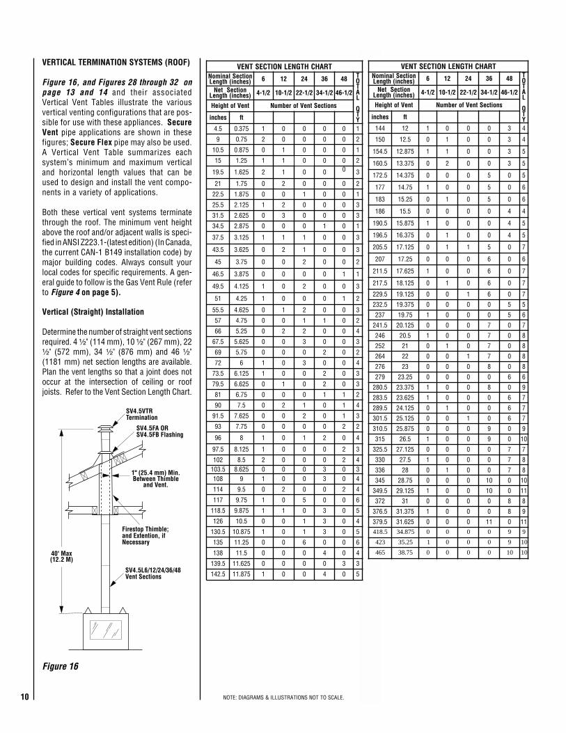
VERTICAL TERMINATION SYSTEMS (ROOF)
Figure 16, and Figures 28 through 32 onpage 13 and 14 and their associatedVertical Vent Tables illustrate the variousvertical venting configurations that are pos-sible for use with these appliances. SecureVent pipe applications are shown in thesefigures; Secure Flex pipe may also be used.A Vertical Vent Table summarizes eachsystem’s minimum and maximum verticaland horizontal length values that can beused to design and install the vent compo-nents in a variety of applications.
Both these vertical vent systems terminatethrough the roof. The minimum vent heightabove the roof and/or adjacent walls is speci-fied in ANSI Z223.1-(latest edition) (In Canada,the current CAN-1 B149 installation code) bymajor building codes. Always consult yourlocal codes for specific requirements. A gen-eral guide to follow is the Gas Vent Rule (referto Figure 4 on page 5).
Vertical (Straight) Installation
Determine the number of straight vent sectionsrequired. 4 ¹⁄₂" (114 mm), 10 ¹⁄₂" (267 mm), 22¹⁄₂" (572 mm), 34 ¹⁄₂" (876 mm) and 46 ¹⁄₂"(1181 mm) net section lengths are available.Plan the vent lengths so that a joint does notoccur at the intersection of ceiling or roofjoists. Refer to the Vent Section Length Chart.
11NOTE: DIAGRAMS & ILLUSTRATIONS NOT TO SCALE.
10¹⁄₂” Min.(267 mm)
10¹⁄₂” Min.(267 mm)
First VentComponentAlign the dimple (four places)with the opening of the lockingincline channel on appliancecollar. Twist vent componentclockwise to engage and seal.
LockingIncline Channel
Dimple
Appliance collar
Vent / Appliance CollarConnection
Align the dimple (four places) of theupper vent section with the opening ofthe locking incline channel on thelower vent section. Twist ventcomponent clockwise to engage andseal until arrow and dimple align.
LockingIncline Channel
Dimple
ArrowConnected
Vent Sections
Vent / Vent SectionConnection
Arrow
Arrow
Figure 17
Figure 19
Figure 18
Figure 20
Note: Trim Thimble/Extension To Desired LengthAnd Pitch At The Roof Line
14" Min.
Pitched Roof
Pitched Roof
Bow Roof
14" Min.
Outer Pipe OfChimney
Outer Pipe OfChimney
Outer Pipe OfChimney14" Min.
FirestopThimble
Extension
13"
FirestopThimble
FirestopThimble
ThimbleSV-FSTFE
Vertical (Offset) Installation
Analyze the vent routing and determine the quan-tities of vent sections and number of elbowsrequired. Refer to Vertical Vent Figures andTables on page 13 and 14 to select the type ofvertical installation desired. Vent sections are avail-able in net lengths of 4 ¹⁄₂" (114 mm), 10 ¹⁄₂" (267mm), 22 ¹⁄₂" (572 mm), 34 ¹⁄₂" (876 mm) and 46 ¹⁄₂"(1181 mm). Refer to the Vent Section LengthChart on page 10 for an aid in selecting lengthcombinations. Elbows are available in 90° and 45°configurations. Refer to Figure 23 for the SV4.5E45and SV4.5E90 elbow dimensional specifications.Where required, a telescopic vent section(SV4.5LA) may be used to provide the installerwith an option in installing in tight and confinedspaces or where the vent run made up of fixedlength pieces develops a joint in a undesirablelocation, or will not build up to the required length.The SV4.5LA Telescopic Vent Section has aneffective length of from 1 ¹⁄₂" (38 mm) to 7 ¹⁄₂" (191mm). The SV4.5LA is fitted with a locking inclinedchannel end (identical to a normal vent sectioncomponent) and a plain end with 3 pilot holes. Slipthe plain end over the locking channel end of astandard SV4.5 vent component the requireddistance and secure with three screws.
Maintain a minimum 1" (25 mm) clearance tocombustible materials for all vertical elements.Clearances for all horizontal elements are 3"(76 mm) on top, 1" (25 mm) on sides and 1"(25 mm) on the bottom.
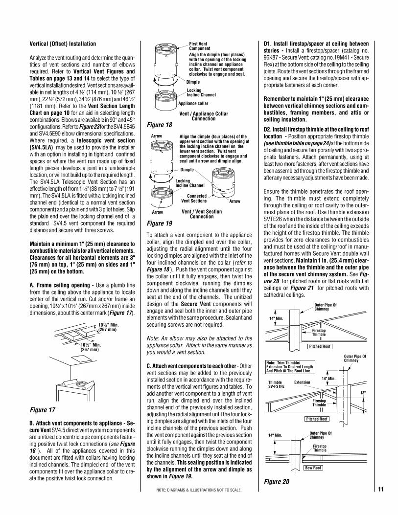
A. Frame ceiling opening - Use a plumb linefrom the ceiling above the appliance to locatecenter of the vertical run. Cut and/or frame anopening, 10¹⁄₂" x 10¹⁄₂" (267mm x 267mm) insidedimensions, about this center mark (Figure 17).
To attach a vent component to the appliancecollar, align the dimpled end over the collar,adjusting the radial alignment until the fourlocking dimples are aligned with the inlet of thefour inclined channels on the collar (refer toFigure 18 ). Push the vent component againstthe collar until it fully engages, then twist thecomponent clockwise, running the dimplesdown and along the incline channels until theyseat at the end of the channels. The unitizeddesign of the Secure Vent components willengage and seal both the inner and outer pipeelements with the same procedure. Sealant andsecuring screws are not required.
Note: An elbow may also be attached to theappliance collar. Attach in the same manner asyou would a vent section.
C. Attach vent components to each other - Othervent sections may be added to the previouslyinstalled section in accordance with the require-ments of the vertical vent figures and tables. Toadd another vent component to a length of ventrun, align the dimpled end over the inclinedchannel end of the previously installed section,adjusting the radial alignment until the four lock-ing dimples are aligned with the inlets of the fourincline channels of the previous section. Pushthe vent component against the previous sectionuntil it fully engages, then twist the componentclockwise running the dimples down and alongthe incline channels until they seat at the end ofthe channels. This seating position is indicatedby the alignment of the arrow and dimple asshown in Figure 19.
B. Attach vent components to appliance - Se-cure Vent SV4.5 direct vent system componentsare unitized concentric pipe components featur-ing positive twist lock connections (see Figure18 ). All of the appliances covered in thisdocument are fitted with collars having lockinginclined channels. The dimpled end of the ventcomponents fit over the appliance collar to cre-ate the positive twist lock connection.
D2. Install firestop thimble at the ceiling to rooflocation - Position appropriate firestop thimble(see thimble table on page 24) at the bottom sideof ceiling and secure temporarily with two appro-priate fasteners. Attach permanently, using atleast two more fasteners, after vent sections havebeen assembled through the firestop thimble andafter any necessary adjustments have been made.
Ensure the thimble penetrates the roof open-ing. The thimble must extend completelythrough the ceiling or roof cavity to the outer-most plane of the roof. Use thimble extensionSVTE26 when the distance between the outsideof the roof and the inside of the ceiling exceedsthe height of the firestop thimble. The thimbleprovides for zero clearances to combustiblesand must be used at the ceiling/roof in manu-factured homes with Secure Vent double wallvent sections. Maintain 1 in. (25.4 mm) clear-ance between the thimble and the outer pipeof the secure vent chimney system. See Fig-ure 20 for pitched roofs or flat roofs with flatceilings or Figure 21 for pitched roofs withcathedral ceilings.
D1. Install firestop/spacer at ceiling betweenstories - Install a firestop/spacer (catalog no.96K87 - Secure Vent; catalog no.19M41 - SecureFlex) at the bottom side of the ceiling to the ceilingjoists. Route the vent sections through the framedopening and secure the firestop/spacer with ap-propriate fasteners at each corner.
Remember to maintain 1" (25 mm) clearancebetween vertical chimney sections and com-bustibles, framing members, and attic orceiling insulation.
12 NOTE: DIAGRAMS & ILLUSTRATIONS NOT TO SCALE.
14" Min.
Outer Pipe OfChimney
Use correct firestopthimble depending on the
pitch of the interiorceiling.
Note: Regular Thimble(SV-FSTFE) Can Be Used
If A Header Is ConstructedAt This Point
C
D
fooRrofsnoisnemiDgnimarFmm(sehcni )
hctiP C D21/0 )762(2/101 )762(2/10121/6 )762(2/101 )503(2121/21 )762(2/101 4/371 )154(
StormCollar
1 inch (25.4 mm)minimum
clearance tocombustibles
SupportStraps
(Plumber’stape)
8 feet (2.4 m)Maximum
Blocking
Note: Secure vent with fasteners at framing.Do not secure plumber’s tape with a fastenerdirectly into the vent pipe.
Figure 24
Figure 25
Figure 27
Figure 22
Figure 23
Figure 21
Figure 26
SV4.5E90(90° Elbow)
8 ¹⁄₈"(206 mm)
Swivel Joint(360° swivel)
4 ¹³⁄₁₆"(122 mm)
SV4.5E45(45° Elbow)
Swivel Joint(360° swivel)
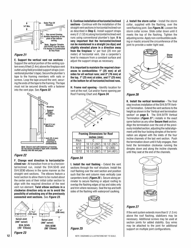
K. Install the vertical termination - The finalstep involves installation of the SV4.5VTR Verti-cal Termination. Extend the vent sections to theheight as shown in the "Vertical vent terminationsection" on page 5. The SV4.5VTR VerticalTermination (Figure 27 ) installs in the exactsame fashion as any other Secure Vent section.Align the termination over the end of the previ-ously installed section, adjusting the radial align-ment until the four locking dimples of the termi-nation are aligned with the inlets of the fourincline channels of the last vent section. Pushthe termination down until it fully engages, thentwist the termination clockwise running thedimples down and along the incline channelsuntil they seat at the end of the channels.
I. Install the roof flashing - Extend the ventsections through the roof structure. Install theroof flashing over the vent section and positionsuch that the vent column rises vertically (usecarpenters level) (Figure 25 ). Secure along pe-rimeter to secure flashing or adjust roofing tooverlap the flashing edges at top and sides onlyand trim where necessary. Seal the top and bothsides of the flashing with waterproof caulking.
J. Install the storm collar - Install the stormcollar, supplied with the flashing, over thevent/flashing joint. See Figure 26. Loosen thestorm collar screw. Slide collar down until itmeets the top of the flashing. Tighten theadjusting screw. Apply non-combustible caulk-ing or mastic around the circumference of thejoint to provide a water tight seal.
E. Support the vertical vent run sections -Support the vertical portion of the venting sys-tem every 8 feet (2.4m) above the fireplace ventoutlet using field provided support straps (con-ventional plumber's tape). Secure the plumber'stape to the framing members with nails orscrews. Loop the tape around the vent, secur-ing the ends of the tape to the framing. The tapemust not be secured directly with a fastenerinto the vent pipe. See Figure 22.
F. Change vent direction to horizontal/in-clined run - At transition from or to a horizon-tal/inclined run, install the SV4.5E45 andSV4.5E90 elbows in the same manner as thestraight vent sections. The elbows feature atwist section to allow them to be routed aboutthe center axis of their initial collar section toalign with the required direction of the nextvent run element. Twist elbow sections in aclockwise direction only so as to avoid thepossiblity of unlocking any of the previouslyconnected vent sections. See Figure 23.
If the vent system extends more than 5' (1.5 m)above the roof flashing, stabilizers may benecessary. Additional screws may be used atsection joints for added stability. Guy wiresmay be attached to the joint for additionalsupport on multiple joint configurations.
G. Continue installation of horizontal/inclinedsections - Continue with the installation of thestraight vent sections in horizontal/inclined runas described in Step C. Install support strapsevery 5' (1.52 m) along horizontal/inclined ventruns using conventional plumber’s tape. It isvery important that the horizontal/inclinedrun be maintained in a straight (no dips) andslightly elevated plane in a direction awayfrom the fireplace ¹⁄₄" per foot (20 mm permeter) of horizontal vent. Use a carpenter’slevel to measure from a constant surface andadjust the support straps as necessary.
It is important to maintain the required clear-ances to combustibles: 1" (25 mm) at allsides for all vertical runs; and 3" (76 mm) atthe top, 1" (25 mm) at sides, and 1" (25 mm)at the bottom for all horizontal/inclined runs.
H. Frame roof opening - Identify location forvent at the roof. Cut and/or frame opening perRoof Framing Chart and Figure 24.
13NOTE: DIAGRAMS & ILLUSTRATIONS NOT TO SCALE.
40 feet (12.2 meters)Maximum
Firestop Thimble
AELBATV M MUMINI mumixaMH
teef )m( teef )m(
1 )503.0( 2 )16.0(
2 )16.0( 4 )222.1(
3 )419.0( 6 )68.1(
4 )22.1( 8 )4.2(
.xaM)m4.21(teef04=H+V.xaM)m4.2(teef8=H
V
H
FirestopThimble
*WallFirestop/Spacer
(SV4.5HF)
*When usingSecure Flex, useFirestop/Spacer
(SF4.5HF)
BELBATV M MUMINI H mumixaM
teef )sretem( teef )sretem(
1 )503.0( 5 )25.1(
2 )016.0( 01 )1.3(
3 )419.0( 51 )56.4(
4 )22.1( 02 )2.6(
V+V 1 .xaM)m4.21(teef04=H+H .xaM)m2.6(teef02=
H
V
V1
Firestop Thimble
*WallFirestop/Spacer
(SV4.5HF)
Firestop Thimble
*When usingSecure Flex, useFirestop/Spacer
(SF4.5HF)
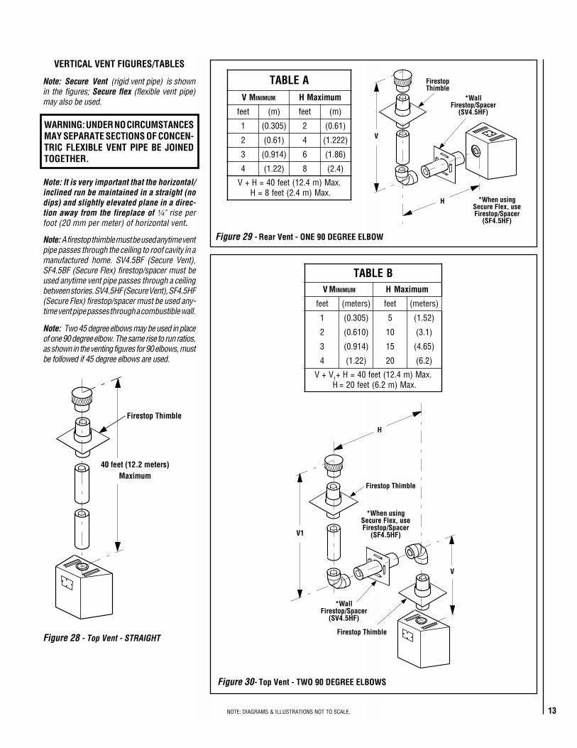
Figure 29 - Rear Vent - ONE 90 DEGREE ELBOW
Figure 28 - Top Vent - STRAIGHT
Figure 30- Top Vent - TWO 90 DEGREE ELBOWS
VERTICAL VENT FIGURES/TABLES
Note: A firestop thimble must be used anytime ventpipe passes through the ceiling to roof cavity in amanufactured home. SV4.5BF (Secure Vent),SF4.5BF (Secure Flex) firestop/spacer must beused anytime vent pipe passes through a ceilingbetween stories. SV4.5HF (Secure Vent), SF4.5HF(Secure Flex) firestop/spacer must be used any-time vent pipe passes through a combustible wall.
Note: Two 45 degree elbows may be used in placeof one 90 degree elbow. The same rise to run ratios,as shown in the venting figures for 90 elbows, mustbe followed if 45 degree elbows are used.
Note: It is very important that the horizontal/inclined run be maintained in a straight (nodips) and slightly elevated plane in a direc-tion away from the fireplace of ¹⁄₄" rise perfoot (20 mm per meter) of horizontal vent.
WARNING: UNDER NO CIRCUMSTANCESMAY SEPARATE SECTIONS OF CONCEN-TRIC FLEXIBLE VENT PIPE BE JOINEDTOGETHER.
Note: Secure Vent (rigid vent pipe) is shownin the figures; Secure flex (flexible vent pipe)may also be used.
14 NOTE: DIAGRAMS & ILLUSTRATIONS NOT TO SCALE.
H1
V
V1
H
Firestop Thimble
*WallFirestop/Spacer
(SV4.5HF)
**Ceiling FirestopSpacer(SV4.5BF)
*When usingSecure Flex, useFirestop/Spacer
(SF4.5HF)
**When usingSecure Flex, useFirestop/Spacer
(SF4.5BF)
V
H1
H
Firestop ThimbleV1 *WallFirestop/Spacer
(SV4.5HF)
*When usingSecure Flex, useFirestop/Spacer
(SF4.5HF)
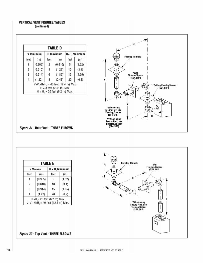
DELBATmuminiMV mumixaMH H+H 1 mumixaM
teef )m( teef )m( teef )m(
1 )503.0( 2 )016.0( 5 )25.1(
2 )016.0( 4 )22.1( 01 )1.3(
3 )419.0( 6 )68.1( 51 )56.4(
4 )22.1( 8 )84.2( 02 )2.6(
V+V 1 H+H+ 1 .xaM)m4.21(teef04=.xaM)m84.2(teef8=H
H+H 1 .xaM)m2.6(teef02=
EELBATV M MUMINI H H+ 1 mumixaM
teef )m( teef )m(
1 )503.0( 5 )25.1(
2 )016.0( 01 )1.3(
3 )419.0( 51 )56.4(
4 )22.1( 02 )2.6(
H+H 1 .xaM)m2.6(teef02=V+V 1 H+H+ 1 .xaM)m4.21(teef04=
Figure 31 - Rear Vent - THREE ELBOWS
Figure 32 - Top Vent - THREE ELBOWS
VERTICAL VENT FIGURES/TABLES(continued)
15NOTE: DIAGRAMS & ILLUSTRATIONS NOT TO SCALE.
VerticalRise
SV4.5E90Elbow
Horizontal / Inclined Run(¹⁄₄" Rise per Foot of Horizontal Run inthe Direction away from the Fireplace) SV4.5 HTS
TerminationShown
*Firestop/Spacer(SV4.5BF)
SV4.5L6/12/24/36/48Vent Sections
Support Bracket SpacingEvery 5 ft (1.52 m)
See figure 22on page 12
for vertical ventsection support.
SV4.5 HTSTerminationShown
SupportBracketsBuilding
SupportFraming
Ceiling Between Stories
Fireplace
ExteriorWall
ExteriorWall
TYPICAL HORIZONTAL VENT INSTALLATION
*When using*Secure Flex, useFirestop/Spacer
(SF4.5BF)
1 in. min.(25.4 mm)
**Note - Firestop/Spacer(SV4.5HF) required but not
shown for clarity.**Note - When using
Secure Flex, useFirestop/Spacer SF4.5HF
Fireplace
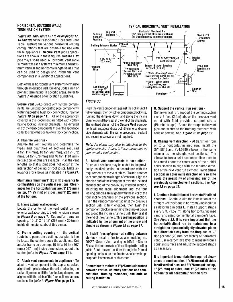
Figure 33
Figure 33, and Figures 37 to 44 on pages 17,18 and 19 and their associated Horizontal VentTable illustrate the various horizontal ventingconfigurations that are possible for use withthese appliances. Secure Vent pipe applica-tions are shown in these figures; Secure Flexpipe may also be used. A Horizontal Vent Tablesummarizes each system’s minimum and maxi-mum vertical and horizontal length values thatcan be used to design and install the ventcomponents in a variety of applications.
Both of these horizontal vent systems terminatethrough an outside wall. Building Codes limit orprohibit terminating in specific areas. Refer toFigure 7 on page 6 for location guidelines.
Secure Vent SV4.5 direct vent system compo-nents are unitized concentric pipe componentsfeaturing positive twist lock connection, (refer toFigure 18 on page 11). All of the appliancescovered in this document are fitted with collarshaving locking inclined channels. The dimpledend of the vent components fit over the appliancecollar to create the positive twist lock connection.
A. Plan the vent run -Analyze the vent routing and determine thetypes and quantities of sections required4 ¹⁄₂" (114 mm), 10 ¹⁄₂" (267 mm), 22 ¹⁄₂" (572mm), 34 ¹⁄₂" (876 mm) and 46 ¹⁄₂" (1181 mm)net section lengths are available. Plan the ventlengths so that a joint does not occur at theintersection of ceiling or roof joists. Make al-lowances for elbows as indicated in Figure 21.
Maintain a minimum 1" (25 mm) clearance tocombustibles on the vertical sections. Clear-ances for the horizontal runs are; 3" (76 mm)on top, 1" (25 mm) on sides, and 1" (25 mm)at the bottom.
B. Frame exterior wall opening -Locate the center of the vent outlet on theexterior wall according to the dimensions shownin Figure 8 on page 7. Cut and/or frame anopening, 10 ¹⁄₂" X 12 ¹⁄₈" (267 mm x 308mm)inside dimensions, about this center.
C. Frame ceiling opening - If the verticalroute is to penetrate a ceiling, use plumb lineto locate the center above the appliance. Cutand/or frame an opening, 10 ¹⁄₂" x 10 ¹⁄₂" (267mm x 267 mm) inside dimensions, about thiscenter (refer to Figure 17 on page 11 ).
D. Attach vent components to appliance - Toattach a vent component to the appliance collar,align the dimpled end over the collar, adjusting theradial alignment until the four locking dimples arealigned with the inlets of the four incline channelson the collar (refer to Figure 18 on page 11).
G. Support the vertical run sections -On the vertical run, support the venting systemevery 8 feet (2.4m) above the fireplace ventoutlet with field provided support straps(Plumber's tape). Attach the straps to the ventpipe and secure to the framing members withnails or screws. See Figure 22 on page 12.
H. Change vent direction - At transition fromor to a horizontal/inclined run, install theSV4.5E45 and SV4.5E90 elbows in the samemanner as the straight vent sections. Theelbows feature a twist section to allow them tobe routed about the center axis of their initialcollar section to align with the required direc-tion of the next vent run element. Twist elbowsections in a clockwise direction only so as toavoid the possiblity of unlocking any of thepreviously connected vent sections. See Fig-ure 23 on page 12.
I. Continue installation of horizontal/inclinedsections - Continue with the installation of thestraight vent sections in horizontal/inclined runas described in Step E. Install support strapsevery 5 ft. (1.52 m) along horizontal/inclinedvent runs using conventional plumber’s tape.See Figure 33. It is very important that thehorizontal/inclined run be maintained in astraight (no dips) and slightly elevated planein a direction away from the fireplace of ¹⁄₄"rise per foot (20 mm per meter) of horizontalvent. Use a carpenter’s level to measure from aconstant surface and adjust the support strapsas necessary.
It is important to maintain the required clear-ances to combustibles: 1" (25 mm) at all sidesfor all vertical runs; and 3" (76 mm) at the top,1" (25 mm) at sides, and 1" (25 mm) at thebottom for all horizontal/inclined runs
HORIZONTAL (OUTSIDE WALL)TERMINATION SYSTEM
Push the vent component against the collar until itfully engages, then twist the component clockwise,running the dimples down and along the inclinechannels until they seat at the end of the channels.The unitized design of the Secure Vent compo-nents will engage and seal both the inner and outerpipe elements with the same procedure. Sealantand securing screws are not required.
Note: An elbow may also be attached to theappliance collar. Attach in the same manner asyou would a vent section.
E. Attach vent components to each other -Other vent sections may be added to the previ-ously installed section in accordance with therequirements of the vent tables. To add anothervent component to a length of vent run, align thedimpled end of the component over the inclinedchannel end of the previously installed section,adjusting the radial alignment until the fourlocking dimples are aligned with the inlets of thefour incline channels of the previous section.Push the vent component against the previoussection until it fully engages, then twist thecomponent clockwise running the dimples downand along the incline channels until they seat atthe end of the channels. This seating position isindicated by the alignment of the arrow anddimple as shown in Figure 19 on page 11.
F. Install firestop/spacer at ceiling betweenstories - Install a firestop/spacer (catalog no.96K87 - Secure Vent; catalog no.19M41 - SecureFlex) at the bottom side of the ceiling to the ceilingjoists. Route the vent sections through the framedopening and secure the firestop/spacer with ap-propriate fasteners at each corner.
Remember to maintain 1" (25 mm) clearancebetween vertical chimney sections and com-bustibles, framing members, and attic orceiling insulation.
16 NOTE: DIAGRAMS & ILLUSTRATIONS NOT TO SCALE.
*Note - When usingSecure Flex, use
Firestop/Spacer SF4.5HF
*Firestop/Spacer (SV4.5HF)shown on the exterior side of thewall. It may also be installed on
the interior side. SV4.5 HTSTermination
Shown.
10¹⁄₂"(267mm)
7"(178)
5¹⁄₈"(130 mm)
12¹⁄₈"(308 mm)
Note: Centerline of Vent Piping isNOT the Same as the Centerline of
the Framed Opening.
6 to 48 inch Vent Section,Telescopic vent section,
Elbow or Appliance Collar
See Figure 8 on page 7for Min. Distance to Base
of Appliance.
Base of Appliance
3"(76 mm)
1"(25.4 mm)
*Firestop/Spacer integral withround termination (SV4.5HTR)
See Venting Figures for Use Restrictions on theSmall Square Horizontal Termination
(SV4.5HTSS) and the Horizontal RoundTermination (SV4.5HTR).
AdapterSV4.5RCH
Siding
Stucco*1¹⁄₄" Maximum Recess ofEither Square Termination intoExterior Finishing Material
Exterior Surface ofFraming5 in. to 9 ¹�₄ in.
(127 to 235 mm)
*Note - The SV4.5HTR Horizontal Round Termination may NOT be recessed at all.
Exterior Surface of Siding
Minimum wall thickness5 in. (127 mm)
Interior Surface ofFinished Wall
Maximum wall thickness9¹�₄ in.(235 mm)
SV4.5HTSSquare Termination
shown
Maximum Extent ofVent Run SectionsRelative to ExteriorSurface of Framing
Last Vent Section. UseT e l e s c o p i c V e n tSection (SV4.5LA), IfNecessary
AdapterSV4.5RCH
SV4.5HTSSquare Termination
Shown
Venting Connection and Exterior Wall Recessing of theHorizontal Square Termination (SV4.5HTS),
Small Square Termination (SV4.5HTSS)or Round Termination ((SV4.5HTR).
See Venting Figures for UseRestrictions on the Small Square
Horizontal Termination (SV4.5HTSS)and the Horizontal RoundTermination (SV4.5HTR).
Note - Firestop/Spacer(SV4.5HF) required but not
shown for clarity.Note - When using SecureFlex, use Firestop/Spacer
SF4.5HF
SV4.5HTR Horizontal Round Termination
See Horizontal Venting Figuresand Tables for Use Restrictions
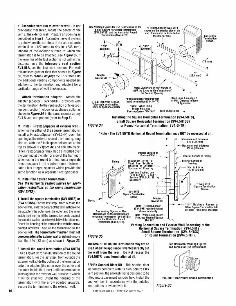
Figure 34
Figure 35
Figure 36
K. Assemble vent run to exterior wall - If notpreviously measured, locate the center of thevent at the exterior wall. Prepare an opening asdescribed in Step B. Assemble the vent systemto point where the terminus of the last section iswithin 5 in. (127 mm) to 9¹⁄₄ in. (235 mm)inboard of the exterior surface to which thetermination is to be attached, see Figure 35. Ifthe terminus of the last section is not within thisdistance, use the telescopic vent sectionSV4.5LA, as the last vent section. For wallthicknesses greater than that shown in Figure35, refer to table 3 on page 17. This table liststhe additional venting components needed (inaddition to the termination and adapter) for aparticular range of wall thicknesses.
L. Attach termination adapter - Attach theadapter (adapter - SV4.5RCH - provided withthe termination) to the vent section or telescop-ing vent section), elbow or appliance collar asshown in Figure 34 in the same manner as anySV4.5 vent component (refer to Step E).
M. Install Firestop/Spacer at exterior wall -When using either of the square terminations,install a Firestop/Spacer (SV4.5HF) over theopening at the exterior side of the framing, longside up, with the 3 inch spacer clearance at thetop as shown in Figure 34, and nail into place.(The Firestop/Spacer may also be installed overthe opening at the interior side of the framing.)When using the round termination, a separatefirestop/spacer is not required since this termi-nation has integral spacers which provide thesame function as a separate firestop/spacer.
1. Install the square termination (SV4.5HTS) or(SV4.5HTSS)- For the last step , from outside theexterior wall, slide the collars of the termination ontothe adapter (the outer over the outer and the innerinside the inner) until the termination seats againstthe exterior wall surface to which it will be attached.Orient the housing of the termination with the arrowpointed upwards. Secure the termination to theexterior wall. The horizontal termination must notbe recessed into the exterior wall or siding by morethan the 1 ¹⁄₄" (32 mm) as shown in Figure 35.
2. Install the round termination (SV4.5HTR)– See Figure 36 for an illustration of the roundtermination. For the last step , from outside theexterior wall, slide the collars of the terminationonto the adapter (the outer over the outer andthe inner inside the inner) until the terminationseats against the exterior wall surface to whichit will be attached. Orient the housing of thetermination with the arrow pointed upwards.Secure the termination to the exterior wall.
N. Install the desired termination -See the horizontal venting figures for appli-cation restrictions on the round termination(SV4.5HTR).
Installing the Square Horizontal Termination (SV4.5HTS),Small Square Horizontal Termination (SV4.5HTSS)
or Round Horizontal Termination (SV4.5HTR).
The SV4.5HTR Round Termination may not beused when the appliance is vented directly outthe wall from the rear. Do Not recess theSV4.5HTR round termination at all.
SFHRK Snorkel Riser Kit – This snorkel riserkit comes complete with its own Secure Flexvent section, the snorkel riser is designed to befitted into a basement window box. Install thesnorkel riser in accordance with the detailedinstructions provided with it.
17NOTE: DIAGRAMS & ILLUSTRATIONS NOT TO SCALE.
3ELBATllaWroiretxEsuoiraVrofderiuqeRstnenopmoCgnitneV-stiKnoitanimreTesehTfoynAgnisUnehW,sessenkcihT
,)STH5.4VS(noitanimreTerauqS)SSTH5.4VS(noitanimreTerauqSllamS
)RTH5.4VS(noitanimreTdnuoRstnenopmoCgnitneV
deriuqeRssenkcihTllaWroiretxE
)mm(sehcniylnOtiKnoitanimreT 4/19ot5 )532ot721(
tnev.ni6dnatiKnoitanimreT)6L5.4VS(noitces 4/19 )943ot532(4/331ot
tnev.ni21dnatiKnoitanimreT)21L5.4VS(noitces )205ot004(4/391ot4/351
cipocseleTdnatiKnoitanimreT.ni6dna)AL5.4VS(noitces
)6L5.4VS(noitcestnev)725ot372(4/302ot4/301
H
*Wall Firestop/Spacer(SV4.5HF)
H = 28 in. (711 mm) Maximum.
7 in. (178 mm)
*When using Secure Flex,use Firestop/Spacer
SF4.5HF
H
*Wall Firestop/Spacer(SV4.5HF)
H = 28 in. (711 mm) Maximum.
8³⁄₁₆ in.(207 mm)
*When using Secure Flex,use Firestop/Spacer
SF4.5HF
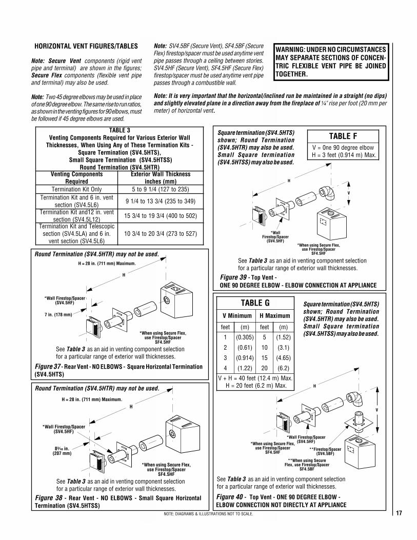
ELBAT Fwobleeerged09en0=V
.xaM)m419.0(teef3=H
H
*WallFirestop/Spacer
(SV4.5HF)
V
*When using Secure Flex,use Firestop/Spacer
SF4.5HF
ELBAT GmuminiMV mumixaMH
teef )m( teef )m(
1 )503.0( 5 )25.1(
2 )16.0( 01 )1.3(
3 )419.0( 51 )56.4(
4 )22.1( 02 )2.6(
.xaM)m4.21(teef04=H+V.xaM)m2.6(teef02=H H
V
*Wall Firestop/Spacer(SV4.5HF)
**When using SecureFlex, use Firestop/Spacer
SF4.5BF
**Firestop/Spacer(SV4.5BF)
*When using Secure Flex,use Firestop/Spacer
SF4.5HF
Figure 39 - Top Vent -ONE 90 DEGREE ELBOW - ELBOW CONNECTION AT APPLIANCE
Figure 40 - Top Vent - ONE 90 DEGREE ELBOW -ELBOW CONNECTION NOT DIRECTLY AT APPLIANCE
Figure 38 - Rear Vent - NO ELBOWS - Small Square HorizontalTermination (SV4.5HTSS)
Figure 37 - Rear Vent - NO ELBOWS - Square Horizontal Termination(SV4.5HTS)
See Table 3 as an aid in venting component selectionfor a particular range of exterior wall thicknesses.
See Table 3 as an aid in venting component selectionfor a particular range of exterior wall thicknesses.
See Table 3 as an aid in venting component selectionfor a particular range of exterior wall thicknesses.
HORIZONTAL VENT FIGURES/TABLES
Note: Secure Vent components (rigid ventpipe and terminal) are shown in the figures;Secure Flex components (flexible vent pipeand terminal) may also be used.
Note: Two 45 degree elbows may be used in placeof one 90 degree elbow. The same rise to run ratios,as shown in the venting figures for 90 elbows, mustbe followed if 45 degree elbows are used.
Note: It is very important that the horizontal/inclined run be maintained in a straight (no dips)and slightly elevated plane in a direction away from the fireplace of ¹⁄₄" rise per foot (20 mm permeter) of horizontal vent.
Square termination (SV4.5HTS)shown; Round Termination(SV4.5HTR) may also be used.Small Square termination(SV4.5HTSS) may also be used.
WARNING: UNDER NO CIRCUMSTANCESMAY SEPARATE SECTIONS OF CONCEN-TRIC FLEXIBLE VENT PIPE BE JOINEDTOGETHER.
Round Termination (SV4.5HTR) may not be used.
Round Termination (SV4.5HTR) may not be used.
Square termination (SV4.5HTS)shown; Round Termination(SV4.5HTR) may also be used.Small Square termination(SV4.5HTSS) may also be used.
See Table 3 as an aid in venting component selectionfor a particular range of exterior wall thicknesses.
Note: SV4.5BF (Secure Vent), SF4.5BF (SecureFlex) firestop/spacer must be used anytime ventpipe passes through a ceiling between stories.SV4.5HF (Secure Vent), SF4.5HF (Secure Flex)firestop/spacer must be used anytime vent pipepasses through a combustible wall.
18 NOTE: DIAGRAMS & ILLUSTRATIONS NOT TO SCALE.
H1
V
H
*Wall Firestop/Spacer(SV4.5HF)
**CeilingFirestop/Spacer
(SV4.5BF)
*Wall Firestop/Spacer(SV4.5HF)
*When using Secure Flex,use Firestop/Spacer
SF4.5HF
**Note - When usingSecure Flex, use
Firestop/Spacer SF4.5BF
HELBATmuminiMV mumixaMH H+H 1 mumixaM
teef )m( teef )m( teef )m(
1 )503.0( 2 )016.0( 5 )25.1(
2 )016.0( 4 )22.1( 01 )1.3(
3 )419.0( 6 )68.1( 51 )56.4(
4 )22.1( 8 )84.2( 02 )2.6(
H+H+V 1 .xaM)m4.21(teef04=.xaM)m84.2(teef8=H
H+H 1 .xaM)m2.6(teef02=
V
H
H1
*Wall Firestop/Spacer(SV4.5HF)
*Wall Firestop/Spacer(SV4.5HF)
*When using Secure Flex,use Firestop/Spacer
SF4.5HF
**CeilingFirestop/Spacer
(SV4.5BF)
**Note - When usingSecure Flex, use
Firestop/Spacer SF4.5BF
JELBATV M MUMINI H + H1 mumixaM
teef )m( teef )m(
1 )503.0( 5 )25.1(
2 )016.0( 01 )1.3(
3 )419.0( 51 )56.4(
4 )22.1( 02 )2.6(
H+H+V 1 .xaM)m4.21(teef04=H+H 1 .xaM)m2.6(teef02=
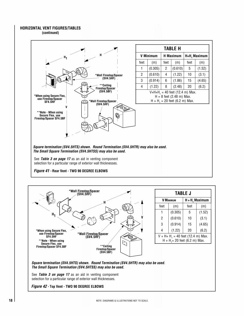
Figure 41 - Rear Vent - TWO 90 DEGREE ELBOWS
Figure 42 - Top Vent - TWO 90 DEGREE ELBOWS
HORIZONTAL VENT FIGURES/TABLES(continued)
See Table 3 on page 17 as an aid in venting componentselection for a particular range of exterior wall thicknesses.
Square termination (SV4.5HTS) shown. Round Termination (SV4.5HTR) may also be used.The Small Square Termination (SV4.5HTSS) may also be used.
See Table 3 on page 17 as an aid in venting componentselection for a particular range of exterior wall thicknesses.
Square termination (SV4.5HTS) shown. Round Termination (SV4.5HTR) may also be used.The Small Square Termination (SV4.5HTSS) may also be used.
19NOTE: DIAGRAMS & ILLUSTRATIONS NOT TO SCALE.
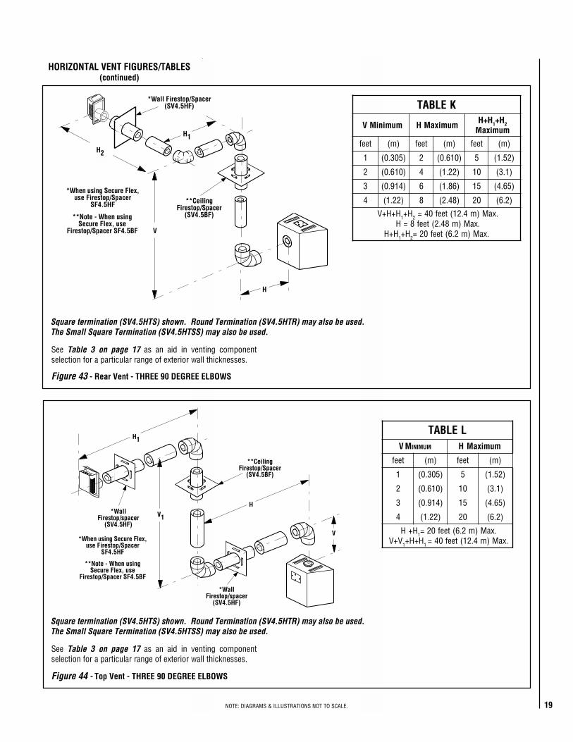
Figure 44 - Top Vent - THREE 90 DEGREE ELBOWS
Figure 43 - Rear Vent - THREE 90 DEGREE ELBOWS
V
H
H1
V1*Wall
Firestop/spacer(SV4.5HF)
*WallFirestop/spacer
(SV4.5HF)
*When using Secure Flex,use Firestop/Spacer
SF4.5HF
**CeilingFirestop/Spacer
(SV4.5BF)
**Note - When usingSecure Flex, use
Firestop/Spacer SF4.5BF
LELBATV M MUMINI H mumixaM
teef )m( teef )m(
1 )503.0( 5 )25.1(
2 )016.0( 01 )1.3(
3 )419.0( 51 )56.4(
4 )22.1( 02 )2.6(
H+H 1 .xaM)m2.6(teef02=V+V 1 H+H+ 1 .xaM)m4.21(teef04=
HORIZONTAL VENT FIGURES/TABLES(continued)
See Table 3 on page 17 as an aid in venting componentselection for a particular range of exterior wall thicknesses.
See Table 3 on page 17 as an aid in venting componentselection for a particular range of exterior wall thicknesses.
Square termination (SV4.5HTS) shown. Round Termination (SV4.5HTR) may also be used.The Small Square Termination (SV4.5HTSS) may also be used.
Square termination (SV4.5HTS) shown. Round Termination (SV4.5HTR) may also be used.The Small Square Termination (SV4.5HTSS) may also be used.
V
H2
H1
H
*Wall Firestop/Spacer(SV4.5HF)
*When using Secure Flex,use Firestop/Spacer
SF4.5HF **CeilingFirestop/Spacer
(SV4.5BF)**Note - When usingSecure Flex, use
Firestop/Spacer SF4.5BF
KELBAT
muminiMV mumixaMH H+H 1 H+ 2mumixaM
teef )m( teef )m( teef )m(
1 )503.0( 2 )016.0( 5 )25.1(
2 )016.0( 4 )22.1( 01 )1.3(
3 )419.0( 6 )68.1( 51 )56.4(
4 )22.1( 8 )84.2( 02 )2.6(
H+H+V 1 H+ 2 .xaM)m4.21(teef04=.xaM)m84.2(teef8=H
H+H 1 H+ 2 .xaM)m2.6(teef02=
20 NOTE: DIAGRAMS & ILLUSTRATIONS NOT TO SCALE.
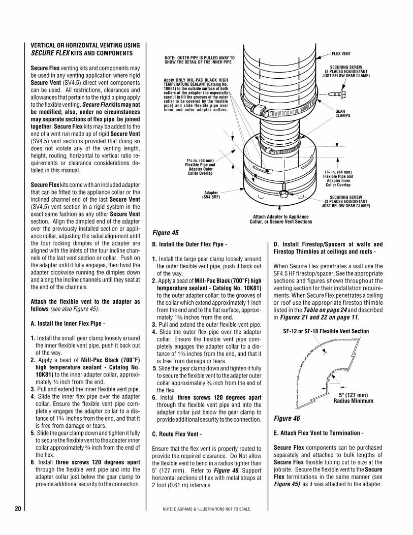
D. Install Firestop/Spacers at walls andFirestop Thimbles at ceilings and roofs -
When Secure Flex penetrates a wall use theSF4.5 HF firestop/spacer. See the appropriatesections and figures shown throughout theventing section for their installation require-ments. When Secure Flex penetrates a ceilingor roof use the appropriate firestop thimblelisted in the Table on page 24 and describedin Figures 21 and 22 on page 11.
E. Attach Flex Vent to Termination -
Secure Flex components can be purchasedseparately and attached to bulk lengths ofSecure Flex flexible tubing cut to size at thejob site. Secure the flexible vent to the SecureFlex terminations in the same manner (seeFigure 45) as it was attached to the adapter.
GEARCLAMPS
Adapter(SV4.5RF)
Apply ONLY MIL-PAC BLACK HIGHTEMPERATURE SEALANT (Catalog No.10K81) to the outside surface of bothcollars of the adapter (be especiallycareful to fill the grooves of the outercollar to be covered by the flexiblepipe) and slide flexible pipe overinner and outer adapter collars.
NOTE: OUTER PIPE IS PULLED AWAY TOSHOW THE DETAIL OF THE INNER PIPE
FLEX VENT
1³⁄₄ in. (44 mm)Flexible Pipe and
Adapter OuterCollar Overlap 1³⁄₄ in. (44 mm)
Flexible Pipe and Adapter InnerCollar Overlap
SECURING SCREW(3 PLACES EQUIDISTANT
JUST BELOW GEAR CLAMP)
Attach Adapter to ApplianceCollar, or Secure Vent Sections
SECURING SCREW(3 PLACES EQUIDISTANT
JUST BELOW GEAR CLAMP)
5" (127 mm)Radius Minimum
SF-12 or SF-18 Flexible Vent Section
Figure 46
Figure 45
VERTICAL OR HORIZONTAL VENTING USINGSECURE FLEX KITS AND COMPONENTS
Secure Flex venting kits and components maybe used in any venting application where rigidSecure Vent (SV4.5) direct vent componentscan be used. All restrictions, clearances andallowances that pertain to the rigid piping applyto the flexible venting. Secure Flex kits may notbe modified; also, under no circumstancesmay separate sections of flex pipe be joinedtogether. Secure Flex kits may be added to theend of a vent run made up of rigid Secure Vent(SV4.5) vent sections provided that doing sodoes not violate any of the venting length,height, routing, horizontal to vertical ratio re-quirements or clearance considerations de-tailed in this manual.
Secure Flex kits come with an included adapterthat can be fitted to the appliance collar or theinclined channel end of the last Secure Vent(SV4.5) vent section in a rigid system in theexact same fashion as any other Secure Ventsection. Align the dimpled end of the adapterover the previously installed section or appli-ance collar, adjusting the radial alignment untilthe four locking dimples of the adapter arealigned with the inlets of the four incline chan-nels of the last vent section or collar. Push onthe adapter until it fully engages, then twist theadapter clockwise running the dimples downand along the incline channels until they seat atthe end of the channels.
Attach the flexible vent to the adapter asfollows (see also Figure 45):
A. Install the Inner Flex Pipe -
1. Install the small gear clamp loosely aroundthe inner flexible vent pipe, push it back outof the way.
2. Apply a bead of Mill-Pac Black (700°F)high temperature sealant - Catalog No.10K81) to the inner adapter collar, approxi-mately ¹⁄₂ inch from the end.
3. Pull and extend the inner flexible vent pipe.4. Slide the inner flex pipe over the adapter
collar. Ensure the flexible vent pipe com-pletely engages the adapter collar to a dis-tance of 1³⁄₄ inches from the end, and that itis free from damage or tears.
5. Slide the gear clamp down and tighten it fullyto secure the flexible vent to the adapter innercollar approximately ³⁄₄ inch from the end ofthe flex.
6. Install three screws 120 degrees apartthrough the flexible vent pipe and into theadapter collar just below the gear clamp toprovide additional security to the connection.
B. Install the Outer Flex Pipe -
1. Install the large gear clamp loosely aroundthe outer flexible vent pipe, push it back outof the way.
2. Apply a bead of Mill-Pac Black (700°F) hightemperature sealant - Catalog No. 10K81)to the outer adapter collar; to the grooves ofthe collar which extend approximately 1 inchfrom the end and to the flat surface, approxi-mately 1³⁄₈ inches from the end.
3. Pull and extend the outer flexible vent pipe.4. Slide the outer flex pipe over the adapter
collar. Ensure the flexible vent pipe com-pletely engages the adapter collar to a dis-tance of 1³⁄₄ inches from the end, and that itis free from damage or tears.
5. Slide the gear clamp down and tighten it fullyto secure the flexible vent to the adapter outercollar approximately ³⁄₄ inch from the end ofthe flex.
6. Install three screws 120 degrees apartthrough the flexible vent pipe and into theadapter collar just below the gear clamp toprovide additional security to the connection.
C. Route Flex Vent -
Ensure that the flex vent is properly routed toprovide the required clearance. Do Not allowthe flexible vent to bend in a radius tighter than5" (127 mm). Refer to Figure 46. Supporthorizontal sections of flex with metal straps at2 foot (0.61 m) intervals.
21NOTE: DIAGRAMS & ILLUSTRATIONS NOT TO SCALE.
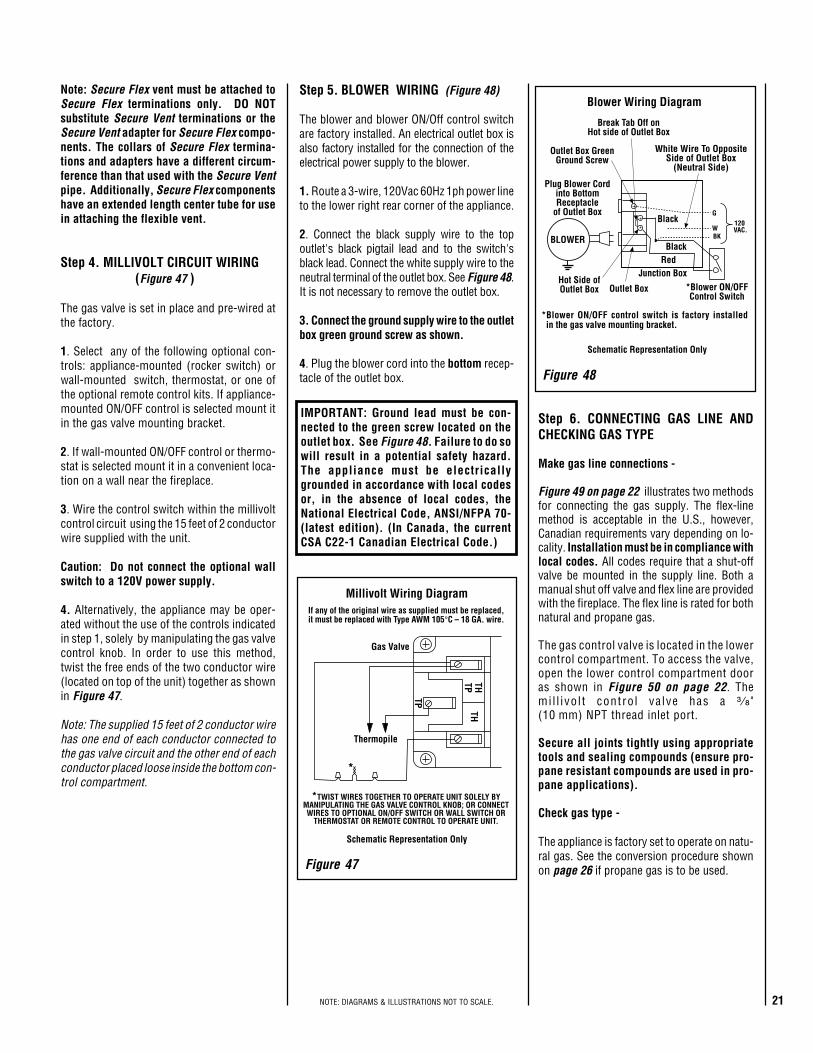
Millivolt Wiring DiagramIf any of the original wire as supplied must be replaced,it must be replaced with Type AWM 105°C – 18 GA. wire.
Thermopile
THTPTH
TP
*TWIST WIRES TOGETHER TO OPERATE UNIT SOLELY BYMANIPULATING THE GAS VALVE CONTROL KNOB; OR CONNECTWIRES TO OPTIONAL ON/OFF SWITCH OR WALL SWITCH OR
THERMOSTAT OR REMOTE CONTROL TO OPERATE UNIT.
*
Schematic Representation Only
Gas Valve
BLOWER
G
W120
VAC.BK
Blower Wiring Diagram
Plug Blower Cordinto BottomReceptacle
of Outlet Box
*Blower ON/OFF control switch is factory installed in the gas valve mounting bracket.
Junction BoxRed
Black
Black
Outlet Box GreenGround Screw
Break Tab Off onHot side of Outlet Box
White Wire To OppositeSide of Outlet Box
(Neutral Side)
Hot Side ofOutlet Box Outlet Box
Schematic Representation Only
*Blower ON/OFFControl Switch
Figure 47
Figure 48
Step 5. BLOWER WIRING (Figure 48)
The blower and blower ON/Off control switchare factory installed. An electrical outlet box isalso factory installed for the connection of theelectrical power supply to the blower.
1. Route a 3-wire, 120Vac 60Hz 1ph power lineto the lower right rear corner of the appliance.
2. Connect the black supply wire to the topoutlet's black pigtail lead and to the switch'sblack lead. Connect the white supply wire to theneutral terminal of the outlet box. See Figure 48.It is not necessary to remove the outlet box.
3. Connect the ground supply wire to the outletbox green ground screw as shown.
4. Plug the blower cord into the bottom recep-tacle of the outlet box.
Step 6. CONNECTING GAS LINE ANDCHECKING GAS TYPE
Make gas line connections -
Figure 49 on page 22 illustrates two methodsfor connecting the gas supply. The flex-linemethod is acceptable in the U.S., however,Canadian requirements vary depending on lo-cality. Installation must be in compliance withlocal codes. All codes require that a shut-offvalve be mounted in the supply line. Both amanual shut off valve and flex line are providedwith the fireplace. The flex line is rated for bothnatural and propane gas.
The gas control valve is located in the lowercontrol compartment. To access the valve,open the lower control compartment dooras shown in Figure 50 on page 22. Themi l l ivo l t contro l va lve has a ³ ⁄ ₈ "(10 mm) NPT thread inlet port.
Secure all joints tightly using appropriatetools and sealing compounds (ensure pro-pane resistant compounds are used in pro-pane applications).
Check gas type -
The appliance is factory set to operate on natu-ral gas. See the conversion procedure shownon page 26 if propane gas is to be used.
IMPORTANT: Ground lead must be con-nected to the green screw located on theoutlet box. See Figure 48. Failure to do sowill result in a potential safety hazard.The appliance must be electricallygrounded in accordance with local codesor, in the absence of local codes, theNational Electrical Code, ANSI/NFPA 70-(latest edition). (In Canada, the currentCSA C22-1 Canadian Electrical Code.)
Note: Secure Flex vent must be attached toSecure Flex terminations only. DO NOTsubstitute Secure Vent terminations or theSecure Vent adapter for Secure Flex compo-nents. The collars of Secure Flex termina-tions and adapters have a different circum-ference than that used with the Secure Ventpipe. Additionally, Secure Flex componentshave an extended length center tube for usein attaching the flexible vent.
Step 4. MILLIVOLT CIRCUIT WIRING(Figure 47 )
The gas valve is set in place and pre-wired atthe factory.
1. Select any of the following optional con-trols: appliance-mounted (rocker switch) orwall-mounted switch, thermostat, or one ofthe optional remote control kits. If appliance-mounted ON/OFF control is selected mount itin the gas valve mounting bracket.
2. If wall-mounted ON/OFF control or thermo-stat is selected mount it in a convenient loca-tion on a wall near the fireplace.
3. Wire the control switch within the millivoltcontrol circuit using the 15 feet of 2 conductorwire supplied with the unit.
Caution: Do not connect the optional wallswitch to a 120V power supply.
4. Alternatively, the appliance may be oper-ated without the use of the controls indicatedin step 1, solely by manipulating the gas valvecontrol knob. In order to use this method,twist the free ends of the two conductor wire(located on top of the unit) together as shownin Figure 47.
Note: The supplied 15 feet of 2 conductor wirehas one end of each conductor connected tothe gas valve circuit and the other end of eachconductor placed loose inside the bottom con-trol compartment.
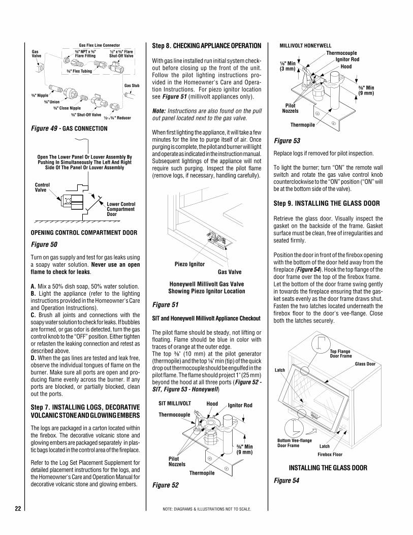
22 NOTE: DIAGRAMS & ILLUSTRATIONS NOT TO SCALE.
Honeywell Millivolt Gas ValveShowing Piezo Ignitor Location
Piezo IgnitorGas Valve
Latch
LatchGlass Door
Firebox Floor
Bottom Vee-flangeDoor Frame
Top FlangeDoor Frame
Gas Stub
¹�₂" x ³�₈" FlareShut-Off Valve
³�₈" NPT x ³�₈"Flare Fitting
³�₈" Nipple
³�₈" Union³�₈" Close Nipple
³�₈" Shut-Off Valve¹�₂" x ³�₈ " Reducer
GasValve
Gas Flex Line Connector
³�₈" Flex Tubing
ControlValve
Lower ControlCompartmentDoor
Open The Lower Panel Or Louver Assembly ByPushing In Simultaneously The Left And Right
Side Of The Panel Or Louver Assembly
Figure 54
Figure 49 - GAS CONNECTION
Figure 53
Figure 51
Figure 50
INSTALLING THE GLASS DOOR
Step 8. CHECKING APPLIANCE OPERATION
With gas line installed run initial system check-out before closing up the front of the unit.Follow the pilot lighting instructions pro-vided in the Homeowner's Care and Opera-tion Instructions. For piezo ignitor locationsee Figure 51 (millivolt appliances only).
Note: Instructions are also found on the pullout panel located next to the gas valve.
When first lighting the appliance, it will take a fewminutes for the line to purge itself of air. Oncepurging is complete, the pilot and burner will lightand operate as indicated in the instruction manual.Subsequent lightings of the appliance will notrequire such purging. Inspect the pilot flame(remove logs, if necessary, handling carefully).
Step 9. INSTALLING THE GLASS DOOR
Retrieve the glass door. Visually inspect thegasket on the backside of the frame. Gasketsurface must be clean, free of irregularities andseated firmly.
Position the door in front of the firebox openingwith the bottom of the door held away from thefireplace (Figure 54). Hook the top flange of thedoor frame over the top of the firebox frame.Let the bottom of the door frame swing gentlyin towards the fireplace ensuring that the gas-ket seats evenly as the door frame draws shut.Fasten the two latches located underneath thefirebox floor to the door's vee-flange. Closeboth the latches securely.
Replace logs if removed for pilot inspection.
To light the burner; turn “ON” the remote wallswitch and rotate the gas valve control knobcounterclockwise to the “ON” position (“ON” willbe at the bottom side of the valve).
SIT and Honeywell Millivolt Appliance Checkout
The pilot flame should be steady, not lifting orfloating. Flame should be blue in color withtraces of orange at the outer edge.The top ³⁄₈" (10 mm) at the pilot generator(thermopile) and the top ¹⁄₈" min (tip) of the quickdrop out thermocouple should be engulfed in thepilot flame. The flame should project 1" (25 mm)beyond the hood at all three ports (Figure 52 -SIT, Figure 53 - Honeywell)
Figure 52
¹⁄₈" Min(3 mm)
ThermocoupleIgnitor Rod
Hood
³⁄₈" Min(9 mm)
Thermopile
MILLIVOLT HONEYWELL
PilotNozzels
SIT MILLIVOLT
Thermocouple
Hood Ignitor Rod
³⁄₈" Min(9 mm)
Thermopile
PilotNozzels
Step 7. INSTALLING LOGS, DECORATIVEVOLCANIC STONE AND GLOWING EMBERS
Turn on gas supply and test for gas leaks usinga soapy water solution. Never use an openflame to check for leaks.
A. Mix a 50% dish soap, 50% water solution.B. Light the appliance (refer to the lightinginstructions provided in the Homeowner's Careand Operation Instructions).C. Brush all joints and connections with thesoapy water solution to check for leaks. If bubblesare formed, or gas odor is detected, turn the gascontrol knob to the “OFF” position. Either tightenor refasten the leaking connection and retest asdescribed above.D. When the gas lines are tested and leak free,observe the individual tongues of flame on theburner. Make sure all ports are open and pro-ducing flame evenly across the burner. If anyports are blocked, or partially blocked, cleanout the ports.
OPENING CONTROL COMPARTMENT DOOR
The logs are packaged in a carton located withinthe firebox. The decorative volcanic stone andglowing embers are packaged separately in plas-tic bags located in the control area of the fireplace.
Refer to the Log Set Placement Supplement fordetailed placement instructions for the logs, andthe Homeowner's Care and Operation Manual fordecorative volcanic stone and glowing embers.
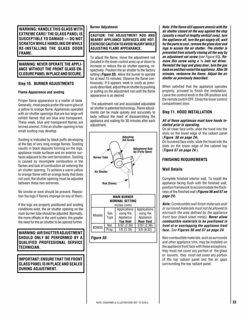
23NOTE: DIAGRAMS & ILLUSTRATIONS NOT TO SCALE.
Adjustment RodUp (Fully Open)
Air Shutter
Burner Tube
AdjustingSet Screw
Rod (Down)
RENRUBNIAMGNITTESLANIMON
)mm(sehcni
sledoM saGepyT
snoitacilppAehtgnisuecnailppAtneVpoT
snoitacilppAehtgnisuecnailppAtneVraeR
53MDB.taN 23/3 )83.2( 23/3 )83.2(.porP 8/1 )81.3( 8/3 )25.9(
Figure 55
Step 11. HOOD INSTALLATION
All of these appliances must have hoods in-stalled prior to operating.On all clean face units, slide the hood into theslots on the lower edge of the radiant panel(Figure 56 on page 24).On louvered face units, slide the hood into theslots on the lower edge of the cabinet top(Figure 57 on page 24 ).
To adjust the flame, move the adjustment rod(located in the lower control area) up or down toincrease or reduce the air shutter opening, re-spectively. Position the air shutter to the factorysetting (Figure 55). Allow the burner to operatefor at least 15 minutes. Observe the flame con-tinuously. If it appears weak or sooty as previ-ously described, adjust the air shutter by pushingor pulling on the adjustment rod until the flameappearance is as desired.
The adjustment rod and associated adjustableair shutter is patented technology. Flame adjust-ments can be made quickly and accurately totaste without the need of disassembling theappliance and waiting for 30 minutes after eachadjustment.
FINISHING REQUIREMENTS
Wall Details
Complete finished interior wall. To install theappliance facing flush with the finished wall,position framework to accommodate the thick-ness of the finished wall (Figures 56 and 57 onpage 24).
Note: Combustible wall finish materials and/or surround materials must not be allowed toencroach the area defined by the appliancefront face (black sheet metal). Never allowcombustible materials to be positioned infront of or overlapping the appliance frontface. See Figures 56 and 57 on page 24.
Step 10. BURNER ADJUSTMENTS
Flame Appearance and sooting
Proper flame appearance is a matter of taste.Generally, most people prefer the warm glow ofa yellow to orange flame. Appliances operatedwith air shutter openings that are too large willexhibit flames that are blue and transparent.These weak, blue and transparent flames aretermed anemic. If the air shutter opening is toosmall sooting may develop.
Sooting is indicated by black puffs developingat the tips of very long orange flames. Sootingresults in black deposits forming on the logs,appliance inside surfaces and on exterior sur-faces adjacent to the vent termination. Sootingis caused by incomplete combustion in theflames and lack of combustion air entering theair shutter opening. To achieve a warm yellowto orange flame with an orange body that doesnot soot, the shutter opening must be adjustedbetween these two extremes.
No smoke or soot should be present. Reposi-tion the logs if flames impinge on any of them.
If the logs are properly positioned and sootingconditions exist, the air shutter opening on themain burner tube should be adjusted. Normally,the more offsets in the vent system, the greaterthe need for the air shutter to be opened further.
Burner Adjustment
CAUTION: THE ADJUSTMENT ROD ANDNEARBY APPLIANCE SURFACES ARE HOT.EXERCISE CAUTION TO AVOID INJURY WHILEADJUSTING FLAME APPEARANCE.
WARNING: AIR SHUTTER ADJUSTMENTSHOULD ONLY BE PERFORMED BY AQUALIFIED PROFESSIONAL SERVICETECHNICIAN.
IMPORTANT: ENSURE THAT THE FRONTGLASS PANEL IS IN PLACE AND SEALEDDURING ADJUSTMENT.
Non-combustible materials, such as surroundsand other appliance trim, may be installed onthe appliance front face with these exceptions:they must not cover any portion of the glassor louvers; they must not cover any portionof the top radiant panel and the air gapssurrounding the top radiant panel.
Note: If the flame still appears anemic with theair shutter closed all the way against the stop(usually a result of lengthy vertical runs), turnthe appliance off, turn the gas supply off, waitfor the parts to cool, remove the glass door andlogs to access the air shutter. The shutter isprevented from actually closing all the way byan adjustment set screw (see Figure 55). Re-move this screw using a ¹⁄₄ inch nut driver.Reinstall the logs and glass door, turn the gasback on and then restart the appliance. After 30minutes, reobserve the flame. Adjust the airshutter as previously described.
When satisfied that the appliance operatesproperly, proceed to finish the installation.Leave the control knob in the ON position andthe remote switch OFF. Close the lower controlcompartment door.
WARNING: NEVER OPERATE THE APPLI-ANCE WITHOUT THE FRONT GLASS EN-CLOSURE PANEL IN PLACE AND SECURE.
WARNING: HANDLE THIS GLASS WITHEXTREME CARE! THE GLASS PANEL ISSUSCEPTIBLE TO DAMAGE — DO NOTSCRATCH WHILE HANDLING OR WHILERE-INSTALLING THE GLASS DOORFRAME.
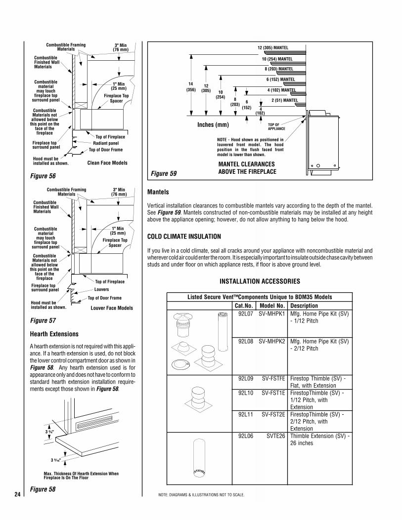
24 NOTE: DIAGRAMS & ILLUSTRATIONS NOT TO SCALE.
3 ³⁄₄"
3 ⁵⁄₁₆"
Max. Thickness Of Hearth Extension WhenFireplace Is On The Floor
sledoM53MDBoteuqinUstnenopmoC™tneVeruceSdetsiL.oN.taC .oNledoM noitpircseD70L29 1KPHM-VS )VS(tiKepiPemoH.gfM
hctiP21/1-
80L29 2KPHM-VS )VS(tiKepiPemoH.gfMhctiP21/2-
90L29 EFTSF-VS -)VS(elbmihTpotseriFnoisnetxEhtiw,talF
01L29 E1TSF-VS -)VS(elbmihTpotseriFhtiw,hctiP21/1
noisnetxE11L29 E2TSF-VS -)VS(elbmihTpotseriF
htiw,hctiP21/2noisnetxE
60L29 62ETVS -)VS(noisnetxEelbmihTsehcni62
12 (305) MANTEL
10 (254) MANTEL
8 (203) MANTEL
6 (152) MANTEL
4 (102) MANTEL
4(102)
14(356)
12(305) 10
(254)2 (51) MANTEL
TOP OFAPPLIANCE
6(152)
NOTE - Hood shown as positioned inlouvered front model. The hoodposition in the flush faced frontmodel is lower than shown.
8(203)
MANTEL CLEARANCESABOVE THE FIREPLACE
Inches (mm)
CombustibleFinished WallMaterials
Top of Fireplace
1" Min(25 mm)
Fireplace TopSpacer
Clean Face Models
Top of Door Frame
Combustiblematerial
may touchfireplace top
surround panel
Hood must beinstalled as shown.
Radiant panel
3" Min(76 mm)
Combustible FramingMaterials
Fireplace topsurround panel
CombustibleMaterials not
allowed belowthis point on the
face of thefireplace
CombustibleFinished WallMaterials
Top of Fireplace
1" Min(25 mm)
Fireplace TopSpacer
Louver Face Models
Top of Door Frame
Combustiblematerial
may touchfireplace top
surround panel
Hood must beinstalled as shown.
3" Min(76 mm)
Combustible FramingMaterials
Fireplace topsurround panel Louvers
CombustibleMaterials not
allowed belowthis point on the
face of thefireplace
Figure 59
Figure 57
Figure 56
Figure 58
INSTALLATION ACCESSORIES
Hearth Extensions
Vertical installation clearances to combustible mantels vary according to the depth of the mantel.See Figure 59. Mantels constructed of non-combustible materials may be installed at any heightabove the appliance opening; however, do not allow anything to hang below the hood.
Mantels
A hearth extension is not required with this appli-ance. If a hearth extension is used, do not blockthe lower control compartment door as shown inFigure 58. Any hearth extension used is forappearance only and does not have to conform tostandard hearth extension installation require-ments except those shown in Figure 58.
COLD CLIMATE INSULATION
If you live in a cold climate, seal all cracks around your appliance with noncombustible material andwherever cold air could enter the room. It is especially important to insulate outside chase cavity betweenstuds and under floor on which appliance rests, if floor is above ground level.
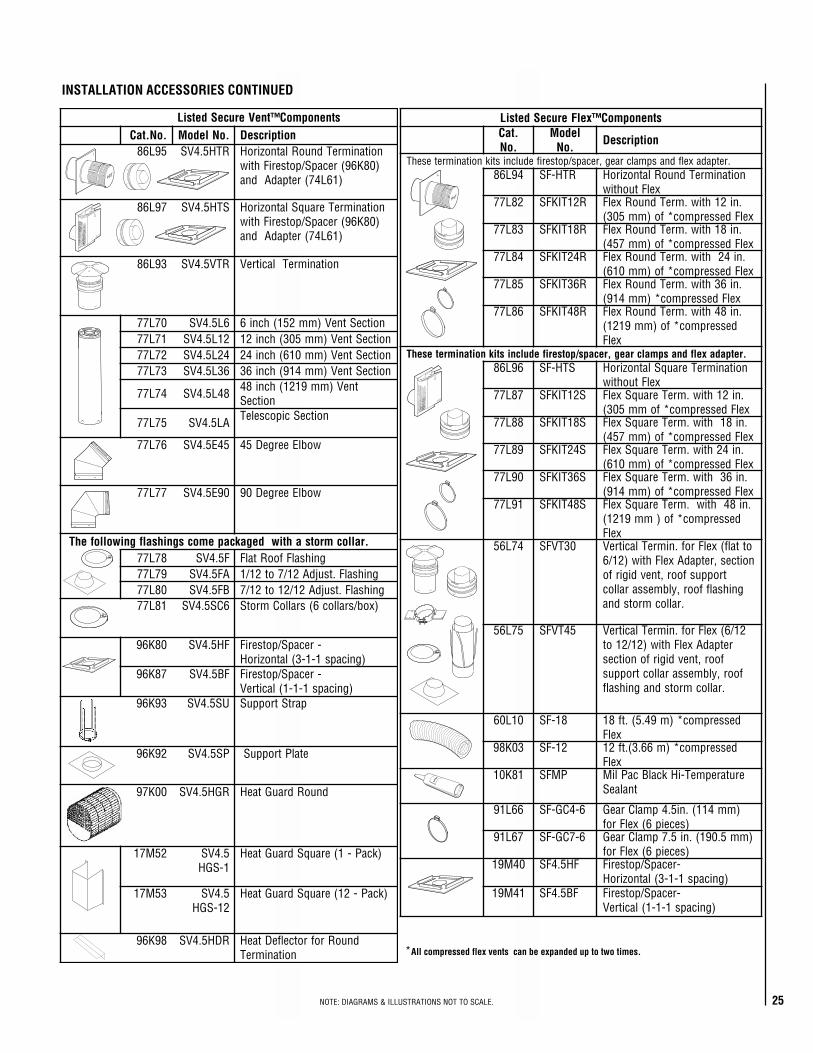
25NOTE: DIAGRAMS & ILLUSTRATIONS NOT TO SCALE.
*All compressed flex vents can be expanded up to two times.
stnenopmoC™xelFeruceSdetsiL.taC.oN
ledoM.oN noitpircseD
.retpadaxelfdnaspmalcraeg,recaps/potserifedulcnistiknoitanimretesehT49L68 RTH-FS noitanimreTdnuoRlatnoziroH
xelFtuohtiw28L77 R21TIKFS .ni21htiw.mreTdnuoRxelF
xelFdesserpmoc*fo)mm503(38L77 R81TIKFS .ni81htiw.mreTdnuoRxelF
xelFdesserpmoc*fo)mm754(48L77 R42TIKFS .ni42htiw.mreTdnuoRxelF
xelFdesserpmoc*fo)mm016(58L77 R63TIKFS .ni63htiw.mreTdnuoRxelF
xelFdesserpmoc*)mm419(68L77 R84TIKFS .ni84htiw.mreTdnuoRxelF
desserpmoc*fo)mm9121(xelF
.retpadaxelfdnaspmalcraeg,recaps/potserifedulcnistiknoitanimretesehT69L68 STH-FS noitanimreTerauqSlatnoziroH
xelFtuohtiw78L77 S21TIKFS .ni21htiw.mreTerauqSxelF
xelFdesserpmoc*fomm503(88L77 S81TIKFS .ni81htiw.mreTerauqSxelF
xelFdesserpmoc*fo)mm754(98L77 S42TIKFS .ni42htiw.mreTerauqSxelF
xelFdesserpmoc*fo)mm016(09L77 S63TIKFS .ni63htiw.mreTerauqSxelF
xelFdesserpmoc*fo)mm419(19L77 S84TIKFS .ni84htiw.mreTerauqSxelF
desserpmoc*fo)mm9121(xelF
47L65 03TVFS ottalf(xelFrof.nimreTlacitreVnoitces,retpadAxelFhtiw)21/6
troppusfoor,tnevdigirfognihsalffoor,ylbmessaralloc
.rallocmrotsdna
57L65 54TVFS 21/6(xelFrof.nimreTlacitreVretpadAxelFhtiw)21/21ot
foor,tnevdigirfonoitcesfoor,ylbmessaralloctroppus
.rallocmrotsdnagnihsalf
01L06 81-FS desserpmoc*)m94.5(.tf81xelF
30K89 21-FS desserpmoc*)m66.3(.tf21xelF
18K01 PMFS erutarepmeT-iHkcalBcaPliMtnalaeS
66L19 6-4CG-FS )mm411(.ni5.4pmalCraeG)seceip6(xelFrof
76L19 6-7CG-FS )mm5.091(.ni5.7pmalCraeG)seceip6(xelFrof
04M91 FH5.4FS -recapS/potseriF)gnicaps1-1-3(latnoziroH
14M91 FB5.4FS -recapS/potseriF)gnicaps1-1-1(lacitreV
Seala
nt
stnenopmoC™tneVeruceSdetsiL.oN.taC .oNledoM noitpircseD59L68 RTH5.4VS noitanimreTdnuoRlatnoziroH
)08K69(recapS/potseriFhtiw)16L47(retpadAdna
79L68 STH5.4VS noitanimreTerauqSlatnoziroH)08K69(recapS/potseriFhtiw
)16L47(retpadAdna
39L68 RTV5.4VS noitanimreTlacitreV
07L77 6L5.4VS noitceStneV)mm251(hcni617L77 21L5.4VS noitceStneV)mm503(hcni2127L77 42L5.4VS noitceStneV)mm016(hcni4237L77 63L5.4VS noitceStneV)mm419(hcni63
47L77 84L5.4VS tneV)mm9121(hcni84noitceS
57L77 AL5.4VS noitceScipocseleT
67L77 54E5.4VS woblEeergeD54
77L77 09E5.4VS woblEeergeD09
.rallocmrotsahtiwdegakcapemocsgnihsalfgniwollofehT87L77 F5.4VS gnihsalFfooRtalF97L77 AF5.4VS gnihsalF.tsujdA21/7ot21/108L77 BF5.4VS gnihsalF.tsujdA21/21ot21/718L77 6CS5.4VS )xob/sralloc6(sralloCmrotS
08K69 FH5.4VS -recapS/potseriF)gnicaps1-1-3(latnoziroH
78K69 FB5.4VS -recapS/potseriF)gnicaps1-1-1(lacitreV
39K69 US5.4VS partStroppuS
29K69 PS5.4VS etalPtroppuS
00K79 RGH5.4VS dnuoRdrauGtaeH
25M71 5.4VS1-SGH
)kcaP-1(erauqSdrauGtaeH
35M71 5.4VS21-SGH
)kcaP-21(erauqSdrauGtaeH
89K69 RDH5.4VS dnuoRrofrotcelfeDtaeHnoitanimreT
INSTALLATION ACCESSORIES CONTINUED
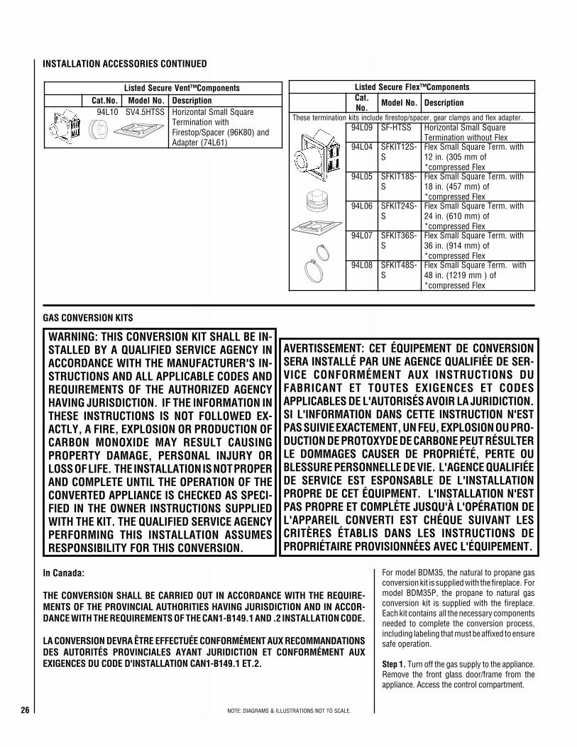
26 NOTE: DIAGRAMS & ILLUSTRATIONS NOT TO SCALE.
stnenopmoC™tneVeruceSdetsiL.oN.taC .oNledoM noitpircseD01L49 SSTH5.4VS erauqSllamSlatnoziroH
htiwnoitanimreTdna)08K69(recapS/potseriF
)16L47(retpadA
stnenopmoC™xelFeruceSdetsiL.taC.oN .oNledoM noitpircseD
.retpadaxelfdnaspmalcraeg,recaps/potserifedulcnistiknoitanimretesehT90L49 SSTH-FS erauqSllamSlatnoziroH
xelFtuohtiwnoitanimreT40L49 -S21TIKFS
Shtiw.mreTerauqSllamSxelF
fomm503(.ni21xelFdesserpmoc*
50L49 -S81TIKFSS
htiw.mreTerauqSllamSxelFfo)mm754(.ni81
xelFdesserpmoc*60L49 -S42TIKFS
Shtiw.mreTerauqSllamSxelF
fo)mm016(.ni42xelFdesserpmoc*
70L49 -S63TIKFSS
htiw.mreTerauqSllamSxelFfo)mm419(.ni63
xelFdesserpmoc*80L49 -S84TIKFS
Shtiw.mreTerauqSllamSxelF
fo)mm9121(.ni84xelFdesserpmoc*
GAS CONVERSION KITS
For model BDM35, the natural to propane gasconversion kit is supplied with the fireplace. Formodel BDM35P, the propane to natural gasconversion kit is supplied with the fireplace.Each kit contains all the necessary componentsneeded to complete the conversion process,including labeling that must be affixed to ensuresafe operation.
Step 1. Turn off the gas supply to the appliance.Remove the front glass door/frame from theappliance. Access the control compartment.
AVERTISSEMENT: CET ÉQUIPEMENT DE CONVERSIONSERA INSTALLÉ PAR UNE AGENCE QUALIFIÉE DE SER-VICE CONFORMÉMENT AUX INSTRUCTIONS DUFABRICANT ET TOUTES EXIGENCES ET CODESAPPLICABLES DE L'AUTORISÉS AVOIR LA JURIDICTION.SI L'INFORMATION DANS CETTE INSTRUCTION N'ESTPAS SUIVIE EXACTEMENT, UN FEU, EXPLOSION OU PRO-DUCTION DE PROTOXYDE DE CARBONE PEUT RÉSULTERLE DOMMAGES CAUSER DE PROPRIÉTÉ, PERTE OUBLESSURE PERSONNELLE DE VIE. L'AGENCE QUALIFIÉEDE SERVICE EST ESPONSABLE DE L'INSTALLATIONPROPRE DE CET ÉQUIPMENT. L'INSTALLATION N'ESTPAS PROPRE ET COMPLÉTE JUSQU'À L'OPÉRATION DEL'APPAREIL CONVERTI EST CHÉQUE SUIVANT LESCRITÈRES ÉTABLIS DANS LES INSTRUCTIONS DEPROPRIÉTAIRE PROVISIONNÉES AVEC L'ÉQUIPEMENT.
INSTALLATION ACCESSORIES CONTINUED
WARNING: THIS CONVERSION KIT SHALL BE IN-STALLED BY A QUALIFIED SERVICE AGENCY INACCORDANCE WITH THE MANUFACTURER'S IN-STRUCTIONS AND ALL APPLICABLE CODES ANDREQUIREMENTS OF THE AUTHORIZED AGENCYHAVING JURISDICTION. IF THE INFORMATION INTHESE INSTRUCTIONS IS NOT FOLLOWED EX-ACTLY, A FIRE, EXPLOSION OR PRODUCTION OFCARBON MONOXIDE MAY RESULT CAUSINGPROPERTY DAMAGE, PERSONAL INJURY ORLOSS OF LIFE. THE INSTALLATION IS NOT PROPERAND COMPLETE UNTIL THE OPERATION OF THECONVERTED APPLIANCE IS CHECKED AS SPECI-FIED IN THE OWNER INSTRUCTIONS SUPPLIEDWITH THE KIT. THE QUALIFIED SERVICE AGENCYPERFORMING THIS INSTALLATION ASSUMESRESPONSIBILITY FOR THIS CONVERSION.
In Canada:
THE CONVERSION SHALL BE CARRIED OUT IN ACCORDANCE WITH THE REQUIRE-MENTS OF THE PROVINCIAL AUTHORITIES HAVING JURISDICTION AND IN ACCOR-DANCE WITH THE REQUIREMENTS OF THE CAN1-B149.1 AND .2 INSTALLATION CODE.
LA CONVERSION DEVRA ÊTRE EFFECTUÉE CONFORMÉMENT AUX RECOMMANDATIONSDES AUTORITÉS PROVINCIALES AYANT JURIDICTION ET CONFORMÉMENT AUXEXIGENCES DU CODE D'INSTALLATION CAN1-B149.1 ET.2.
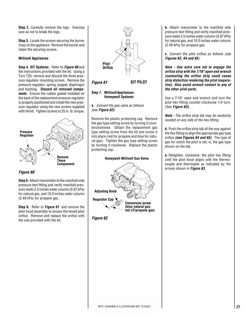
27NOTE: DIAGRAMS & ILLUSTRATIONS NOT TO SCALE.
PilotOrifice
PressureRegulator
RemoveTheseComponents
Figure 60
Figure 61 SIT PILOT
Step 2. Carefully remove the logs. Exercisecare as not to break the logs.
Step 3. Locate the screws securing the burner(tray) to the appliance. Remove the burner andretain the securing screws.
Millivolt Appliances
Step 4. SIT Systems - Refer to Figure 60 andthe instructions provided with the kit. Using aTorx T20, remove and discard the three pres-sure regulator mounting screws. Remove thepressure regulator, spring, poppet, diaphragmand bushing. Discard all removed compo-nents. Ensure the rubber gasket installed onthe back of the replacement pressure regulatoris properly positioned and install the new pres-sure regulator using the new screws suppliedwith the kit. Tighten screws to 25 In. lb. torque.
Step 5. Attach manometer to the manifold sidepressure test fitting and verify manifold pres-sure reads 3.5 inches water column (0.87 kPa)for natural gas, and 10.0 inches water column(2.49 kPa) for propane gas.
Step 6. Refer to Figure 61 and remove thepilot hood assembly to access the hexed pilotorifice. Remove and replace the orifice withthe one provided with the kit.
Step 7. Millivolt Appliances -Honeywell Systems
a. Convert the gas valve as follows(see Figure 62):
Remove the plastic protecting cap. Removethe gas type setting screw by turning it coun-terclockwise. Obtain the replacement gastype setting screw from the kit and screw itinto place (red for propane and blue for natu-ral gas). Tighten the gas type setting screwby turning it clockwise. Replace the plasticprotecting cap.
b. Attach manometer to the manifold sidepressure test fitting and verify manifold pres-sure reads 3.5 inches water column (0.87 kPa)for natural gas, and 10.0 inches water column(2.49 kPa) for propane gas.
c. Convert the pilot orifice as follows (seeFigures 63, 64 and 65):
Note - Use extra care not to engage theorifice strip with the 7/16" open end wrench(contacting the orifice strip could causestrip distortion rendering the pilot inopera-tive). Also avoid wrench contact to any ofthe other pilot parts.
Use a 7/16" open end wrench and turn thepilot hex fitting counter-clockwise 1/4 turn.(See Figure 63).
Note - The orifice strip tab may be randomlylocated on any side of the hex fitting.
d. Push the orifice strip tab all the way againstthe hex fitting to align the appropriate gas typeorifice (see Figures 64 and 65). The type ofgas for which the pilot is set, is, the gas typeshown on the tab.
e. Retighten, clockwise, the pilot hex fittinguntil the pilot hood aligns with the thermo-couple and thermopile as indicated by thearrows shown in Figure 63.
Figure 62
Adjusting Knob
Conversion screw(blue natural gas;red LP/propane gas)
Regulator Cap
Honeywell Millivolt Gas Valve
NOTE: DIAGRAMS & ILLUSTRATIONS NOT TO SCALE.
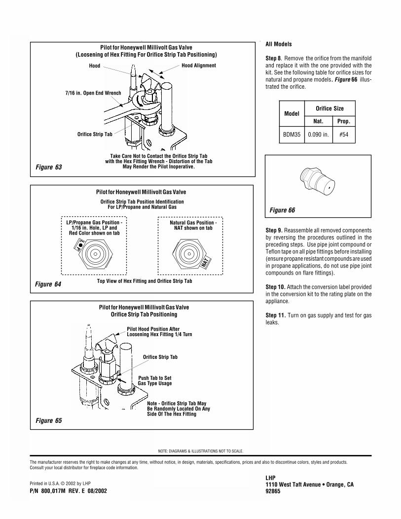
28 NOTE: DIAGRAMS & ILLUSTRATIONS NOT TO SCALE.
Figure 66
All Models
Step 8. Remove the orifice from the manifoldand replace it with the one provided with thekit. See the following table for orifice sizes fornatural and propane models. Figure 66 illus-trated the orifice.
Step 9. Reassemble all removed componentsby reversing the procedures outlined in thepreceding steps. Use pipe joint compound orTeflon tape on all pipe fittings before installing(ensure propane resistant compounds are usedin propane applications, do not use pipe jointcompounds on flare fittings).
Step 10. Attach the conversion label providedin the conversion kit to the rating plate on theappliance.
Step 11. Turn on gas supply and test for gasleaks.
Pilot for Honeywell Millivolt Gas Valve(Loosening of Hex Fitting For Orifice Strip Tab Positioning)
Pilot for Honeywell Millivolt Gas Valve
Figure 65
Pilot for Honeywell Millivolt Gas ValveOrifice Strip Tab Positioning
Figure 63
Figure 64
ledoMeziSecifirO
.taN .porP
53MDB .ni090.0 45#
Natural Gas Position -NAT shown on tab
LP/Propane Gas Position -1/16 in. Hole, LP and
Red Color shown on tab
NAT
PL
Orifice Strip Tab Position IdentificationFor LP/Propane and Natural Gas
Top View of Hex Fitting and Orifice Strip Tab
Orifice Strip Tab
Pilot Hood Position AfterLoosening Hex Fitting 1/4 Turn
Push Tab to SetGas Type Usage
Note - Orifice Strip Tab MayBe Randomly Located On AnySide Of The Hex Fitting
Hood AlignmentHood
7/16 in. Open End Wrench
Orifice Strip Tab
Take Care Not to Contact the Orifice Strip Tabwith the Hex Fitting Wrench - Distortion of the Tab
May Render the Pilot Inoperative.
The manufacturer reserves the right to make changes at any time, without notice, in design, materials, specifications, prices and also to discontinue colors, styles and products.Consult your local distributor for fireplace code information.
Printed in U.S.A. © 2002 by LHP
P/N 800,017M REV. E 08/2002
LHP1110 West Taft Avenue • Orange, CA92865
NOTE: DIAGRAMS & ILLUSTRATIONS NOT TO SCALE.