Embed Size (px)
Citation preview
1
PH3Z
Installation Instructions
13 SEER SINGLE---PACKAGED HEAT PUMP SYSTEMWITH R---22 REFRIGERANTSINGLE AND THREE PHASE
2 TO 5 NOMINAL TONS (SIZES 024---060)
NOTE: Read the entire instruction manual before starting theinstallation.
TABLE OF CONTENTSPAGE
SAFETY CONSIDERATIONS 2. . . . . . . . . . . . . . . . . . . . . . . . .
INTRODUCTION 2. . . . . . . . . . . . . . . . . . . . . . . . . . . . . . . . . . .
RECEIVING AND INSTALLATION 2--7. . . . . . . . . . . . . . . . . .
Check Equipment 2. . . . . . . . . . . . . . . . . . . . . . . . . . . . . . . . . .
Identify Unit 2. . . . . . . . . . . . . . . . . . . . . . . . . . . . . . . . . . . .
Inspect Shipment 2. . . . . . . . . . . . . . . . . . . . . . . . . . . . . . . . .
Provide Unit Support 2. . . . . . . . . . . . . . . . . . . . . . . . . . . . . . .
Slab Mount 2. . . . . . . . . . . . . . . . . . . . . . . . . . . . . . . . . . . . .
Ground Mount 2. . . . . . . . . . . . . . . . . . . . . . . . . . . . . . . . . .
Provide Clearances 2. . . . . . . . . . . . . . . . . . . . . . . . . . . . . . . . .
Place Unit 2. . . . . . . . . . . . . . . . . . . . . . . . . . . . . . . . . . . . . . . .
Select and Install Ductwork 2. . . . . . . . . . . . . . . . . . . . . . . . . . .
Configuring Units for Downflow (Vertical) Discharge 3. . . .
Connect Condensate Drain 3. . . . . . . . . . . . . . . . . . . . . . . . . . .
Install Electrical Connections 5. . . . . . . . . . . . . . . . . . . . . . . . .
High--Voltage Connections 5. . . . . . . . . . . . . . . . . . . . . . . . .
Routing Power Leads Into Unit 6. . . . . . . . . . . . . . . . . . . . . .
Connecting Ground Lead to Unit Ground 6. . . . . . . . . . . . . .
Routing Control Power Wires 6. . . . . . . . . . . . . . . . . . . . . .
Accessory Electric Heat Wiring 6. . . . . . . . . . . . . . . . . . . . . .
PRE--START--UP 7. . . . . . . . . . . . . . . . . . . . . . . . . . . . . . . . . . . .
START--UP 7--16. . . . . . . . . . . . . . . . . . . . . . . . . . . . . . . . . . . . . .
Check for Refrigerant Leaks 7. . . . . . . . . . . . . . . . . . . . . . . . . .
Start--Up Cooling and Make Adjustments 7. . . . . . . . . . . . . . . .
Checking Cooling and Heating Control Operation 7. . . . . . .
Refrigerant Charge 8. . . . . . . . . . . . . . . . . . . . . . . . . . . . . . . . .
No Charge 8. . . . . . . . . . . . . . . . . . . . . . . . . . . . . . . . . . . . . .
Low Charge Cooling 8. . . . . . . . . . . . . . . . . . . . . . . . . . . . . .
Heating Mode Charge 9. . . . . . . . . . . . . . . . . . . . . . . . . . . . .
Indoor Airflow and Airflow Adjustments 9. . . . . . . . . . . . . . . .
Unit Controls 9. . . . . . . . . . . . . . . . . . . . . . . . . . . . . . . . . . . . .
High--Pressure Relief Valve 9. . . . . . . . . . . . . . . . . . . . . . . . .
Loss--of--Charge Switch 9. . . . . . . . . . . . . . . . . . . . . . . . . . .
Compressor Overload 9. . . . . . . . . . . . . . . . . . . . . . . . . . . . .
Compressor Rotation 9. . . . . . . . . . . . . . . . . . . . . . . . . . . . . .
Sequence of Operation 9. . . . . . . . . . . . . . . . . . . . . . . . . . . . . .
Fan Operation 9. . . . . . . . . . . . . . . . . . . . . . . . . . . . . . . . . . .
A05194
Fig. 1 -- Unit PH3Z
Cooling Operation 9, 16. . . . . . . . . . . . . . . . . . . . . . . . . . . . .
Heating Operation 16. . . . . . . . . . . . . . . . . . . . . . . . . . . . . . .
Continuous Fan 16. . . . . . . . . . . . . . . . . . . . . . . . . . . . . . . . .
Defrost 16. . . . . . . . . . . . . . . . . . . . . . . . . . . . . . . . . . . . . . .
Electric Resistance Heating 16. . . . . . . . . . . . . . . . . . . . . . . .
MAINTENANCE 16--19. . . . . . . . . . . . . . . . . . . . . . . . . . . . . . . .
Air Filter 17. . . . . . . . . . . . . . . . . . . . . . . . . . . . . . . . . . . . . . . .
Unit Top Removal 17. . . . . . . . . . . . . . . . . . . . . . . . . . . . . . . . .
Indoor Blower and Motor 17. . . . . . . . . . . . . . . . . . . . . . . . . . .
Outdoor Coil, Indoor Coil, and Condensate Drain Pan 18. . . . .
Outdoor Fan 18. . . . . . . . . . . . . . . . . . . . . . . . . . . . . . . . . . . . .
Electrical Controls and Wiring 18. . . . . . . . . . . . . . . . . . . . . . .
Refrigerant Circuit 18. . . . . . . . . . . . . . . . . . . . . . . . . . . . . . . . .
Indoor Airflow 19. . . . . . . . . . . . . . . . . . . . . . . . . . . . . . . . . . .
Metering Devices 19. . . . . . . . . . . . . . . . . . . . . . . . . . . . . . . . .
Liquid Line Strainers 19. . . . . . . . . . . . . . . . . . . . . . . . . . . . . . .
High Flow Valves 19. . . . . . . . . . . . . . . . . . . . . . . . . . . . . . . . .
TROUBLESHOOTING 19. . . . . . . . . . . . . . . . . . . . . . . . . . . . . .
START--UP CHECKLIST 19. . . . . . . . . . . . . . . . . . . . . . . . . . . .

2
SAFETY CONSIDERATIONSInstallation and servicing of this equipment can be hazardous dueto mechanical and electrical components. Only trained andqualified personnel should install, repair, or service this equipment.
Untrained personnel can perform basic maintenance functions suchas cleaning and replacing air filters. All other operations must beperformed by trained service personnel. When working on thisequipment, observe precautions in the literature, on tags, and onlabels attached to or shipped with the unit and other safetyprecautions that may apply.
Follow all safety codes. Installation must be in compliance withlocal and national building codes. Wear safety glasses, protectiveclothing, and work gloves. Have fire extinguisher available. Readthese instructions thoroughly and follow all warnings or cautionsincluded in literature and attached to the unit.
Recognize safety information. This is the safety--alert symbol .When you see this symbol on the unit and in instructions or manu-als, be alert to the potential for personal injury. Understand thesesignal words: DANGER, WARNING, and CAUTION. Thesewords are used with the safety--alert symbol. DANGER identifiesthe most serious hazards which will result in severe personal injuryor death. WARNING signifies hazards which could result in per-sonal injury or death. CAUTION is used to identify unsafe practic-es which may result in minor personal injury or product and prop-erty damage. NOTE is used to highlight suggestions which willresult in enhanced installation, reliability, or operation.
ELECTRICAL SHOCK HAZARD
Failure to follow this warning could result in personalinjury or death.
Before installing or servicing system, always turn off mainpower to system. There may be more than one disconnectswitch. Turn off accessory heater power switch ifapplicable.
! WARNING
INTRODUCTIONThe PH3Z packaged heat pump is fully self--contained anddesigned for outdoor installation (See Fig. 1). Standard units areshipped in a horizontal--discharge configuration for installation ona ground--level slab or directly on the ground if local codes permit.Standard units can be converted to downflow (vertical) dischargeconfigurations for rooftop applications with a field suppliedplenum.
RECEIVING AND INSTALLATIONStep 1 — Check EquipmentIDENTIFY UNIT
The unit model number and serial number are printed on the unitinformative plate. Check this information against shipping papers.
INSPECT SHIPMENT
Inspect for shipping damage while unit is still on shipping pallet. Ifunit appears to be damaged or is torn loose from its anchorage,have it examined by transportation inspectors before removal.Forward claim papers directly to transportation company.Manufacturer is not responsible for any damage incurred in transit.Check all items against shipping list. Immediately notify thenearest Payne office if any item is missing. To prevent loss ordamage, leave all parts in original packages until installation.
Step 2 — Provide Unit SupportFor hurricane tie downs, contact distributor for details and PE(Professional Engineering) Certificate, if required.
SLAB MOUNT
Place the unit on a solid, level concrete pad that is a minimum of 4in. thick with 2 in. (51 mm) above grade. The slab should extendapproximately 2 in. (51 mm) beyond the casing on all 4 sides ofthe unit. Do not secure the unit to the slab except when required bylocal codes.
A 6--in. wide gravel apron should be used around the flat surface toprevent airflow blockage by grass or shrubs. The unit should belevel to within 1/4 in. (6.4 mm). This is necessary for the unit drainto function properly.
GROUND MOUNT
The unit may be installed either on a slab or placed directly on theground if local codes permit. Place the unit on level groundprepared with gravel for condensate discharge.
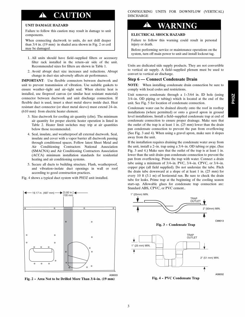
Step 3 — Provide ClearancesThe required minimum service clearances are shown in Fig. 5.Adequate ventilation and outdoor air must be provided.
The outdoor fan draws air through the outdoor coil and dischargesit through the top fan grille. Be sure that the fan discharge does notrecirculate to the outdoor coil. Do not locate the unit in either acorner or under an overhead obstruction. The minimum clearanceunder a partial overhang (such as a normal house overhang) is 48in. (1219 mm) above the unit top. The maximum horizontalextension of a partial overhang must not exceed 48 in. (1219 mm).
IMPORTANT: Do not restrict outdoor airflow. An air restrictionat either the outdoor--air inlet or the fan discharge may bedetrimental to compressor life.
Do not place the unit where water, ice, or snow from an overhangor roof will damage or flood the unit. Do not install the unit oncarpeting or other combustible materials. Slab--mounted unitsshould be at least 4 in. above the highest expected water and runofflevels. Do not use unit if it has been under water.
Step 4 — Place UnitUnit can be moved with the rigging holds provided in the unitbase. Refer to Table 1 for operating weights. Use extreme cautionto prevent damage when moving the unit. Unit must remain in anupright position during all moving operations. The unit must belevel within 1/4 in. (6.4 mm) for proper condensate drainage; theground--level pad must be level before setting the unit in place.When a field--fabricated support is used, be sure that the support islevel and that it properly supports the unit.
Step 5 — Select and Install DuctworkThe design and installation of the duct system must be inaccordance with the standards of the NFPA for installation ofnon--residence type air conditioning and ventilating systems,NFPA 90A or residence type, NFPA 90B and/or local codes andordinances.
Select and size ductwork, supply--air registers, and return air grillesaccording to ASHRAE (American Society of Heating,Refrigeration, and Air Conditioning Engineers) recommendations.
Use the duct flanges provided on the supply-- and return--airopenings on the side of the unit. See Fig. 5 for connection sizesand locations. The 14--in. round duct collars are shipped inside theunit attached to the base pan in the indoor blower compartment.They are field--installed and must be removed from the indoorblower compartment prior to start--up, even if they are not used forinstallation.
When designing and installing ductwork, consider the following:
PH3Z
3
UNIT DAMAGE HAZARD
Failure to follow this caution may result in damage to unitcomponents.
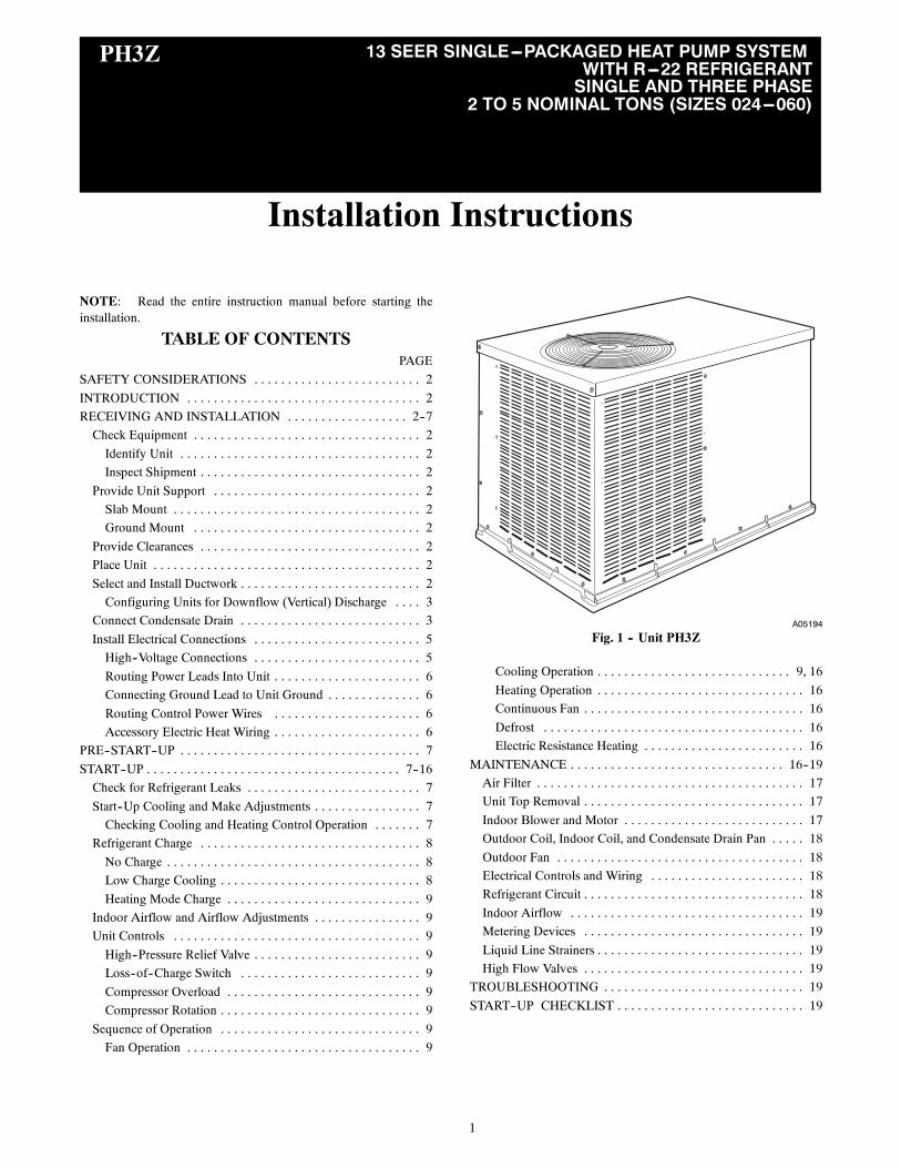
When connecting ductwork to units, do not drill deeperthan 3/4 in. (19 mm) in shaded area shown in Fig. 2 or coilmay be damaged.
CAUTION!
1. All units should have field--supplied filters or accessoryfilter rack installed in the return--air side of the unit.Recommended sizes for filters are shown in Table 1.
2. Avoid abrupt duct size increases and reductions. Abruptchange in duct size adversely affects air performance.
IMPORTANT: Use flexible connectors between ductwork andunit to prevent transmission of vibration. Use suitable gaskets toensure weather--tight and air--tight seal. When electric heat isinstalled, use fireproof canvas (or similar heat resistant material)connector between ductwork and unit discharge connection. Ifflexible duct is used, insert a sheet metal sleeve inside duct. Heatresistant duct connector (or sheet metal sleeve) must extend 24--in.(610 mm) from electric heater element.
3. Size ductwork for cooling air quantity (cfm). The minimumair quantity for proper electric heater operation is listed inTable 2. Heater limit switches may trip at air quantitiesbelow those recommended.
4. Seal, insulate, and weatherproof all external ductwork. Seal,insulate and cover with a vapor barrier all ductwork passingthrough conditioned spaces. Follow latest Sheet Metal andAir Conditioning Contractors National Association(SMACNA) and Air Conditioning Contractors Association(ACCA) minimum installation standards for residentialheating and air conditioning systems.
5. Secure all ducts to building structure. Flash, weatherproof,and vibration--isolate duct openings in wall or roofaccording to good construction practices.
Fig. 4 shows a typical duct system with PH3Z unit installed.
19.17 in. (487 mm) 3.92 in.(100 mm)
A08003
Fig. 2 -- Area Not to be Drilled More Than 3/4--in. (19 mm)
CONFIGURING UNITS FOR DOWNFLOW (VERTICAL)DISCHARGE
ELECTRICAL SHOCK HAZARD
Failure to follow this warning could result in personalinjury or death.
Before performing service or maintenance operations on thesystem, turn off main power to unit and install lockout tag.
! WARNING
Units are dedicated side supply products. They are not convertibleto vertical air supply. A field--supplied plenum must be used toconvert to vertical air discharge.
Step 6 — Connect Condensate DrainNOTE: When installing condensate drain connection be sure tocomply with local codes and restrictions.
Unit removes condensate through a 1--3/64 in. ID hole (using3/4--in. OD piping or tubing) which is located at the end of theunit. See Fig. 5 for location of condensate connection.
Condensate water can be drained directly onto the roof in rooftopinstallations (where permitted) or onto a gravel apron in groundlevel installations. Install a field--supplied condensate trap at end ofcondensate connection to ensure proper drainage. Make sure thatthe outlet of the trap is at least 1 in. (25 mm) lower than the drainpan condensate connection to prevent the pan from overflowing(See Fig. 3 and 4). When using a gravel apron, make sure it slopesaway from the unit.
If the installation requires draining the condensate water away fromthe unit, install a 2--in. trap using a 3/4--in. OD tubing or pipe. (SeeFig. 3 and 4.) Make sure that the outlet of the trap is at least 1 in.lower than the unit drain--pan condensate connection to prevent thepan from overflowing. Prime the trap with water. Connect a draintube using a minimum of 3/4--in. PVC, 3/4--in. CPVC, or 3/4--in.copper pipe (all field supplied). Do not undersize the tube. Pitchthe drain tube downward at a slope of at least 1 in. (25 mm) forevery 10 ft (3.1 m) of horizontal run. Be sure to check the draintube for leaks. Prime trap at the beginning of the cooling seasonstart--up. Allowable glues for condensate trap connection are:Standard ABS, CPVC, or PVC cement..
1” (25mm) MIN.
2” (50mm) MIN.
TRAPOUTLET
C99013
Fig. 3 -- Condensate Trap
TRAPOUTLET
2" (51 mm) MIN.
1" (25 mm) MIN.
A08002
Fig. 4 -- PVC Condensate Trap
PH3Z
4
A05201
UNIT ELECTRICALCHARACTERISTICS
UNIT WEIGHT UNIT HEIGHTIN. [MM]
CENTER OF GRAVITYIN. [MM]
lb kg A X Y ZPH3Z024 208/230--1--60 293 133 30.13 [765] 14.0 [356] 19.0 [483] 15.0 [381]
PH3Z030 208/230--1--60, 208/230--3--60 324 147 34.13 [867] 14.0 [356] 19.0 [483] 16.0 [406]
PH3Z036 208/230--1--60, 208/230--3--60 377 171 42.13 [1070] 14.0 [356] 19.0 [483] 19.8 [503]
PH3Z042 208/230--1--60, 208/230--3--60 389 177 42.13 [1070] 14.0 [356] 19.0 [483] 21.9 [556]
PH3Z048 208/230--1--60, 208/230--3--60 384 175 42.13 [1070] 14.0 [356] 19.0 [483] 19.8 [503]
PH3Z060 208/230--1--60, 208/230--3--60 433 197 42.13 [1070] 14.0 [356] 19.0 [483] 21.9 [556]
Fig. 5 -- Unit Base Dimensions, PH3Z024--060
TOP COVER
INDOORTHERMOSTAT
DISCONNECTPER NEC(UNIT ANDELECTRICHEATER)
FROMPOWERSOURCE
RETURNAIR
POWER ANDLOW-VOLTAGEENTRY
COMPOSITERUST-PROOFBASEPAN
CONDENSATEDRAINCONNECTION
Power Wiring
Control Wiring
Condenser Airflow
Evaporator Airflow
A08207
Fig. 6 -- Typical Installation
PH3Z
5
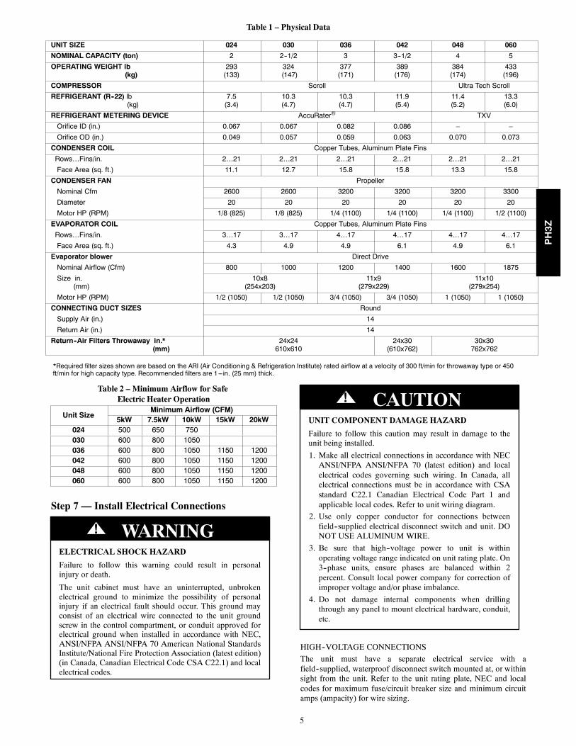
Table 1 – Physical Data
UNIT SIZE 024 030 036 042 048 060
NOMINAL CAPACITY (ton) 2 2--1/2 3 3--1/2 4 5
OPERATING WEIGHT lb(kg)
293(133)
324(147)
377(171)
389(176)
384(174)
433(196)
COMPRESSOR Scroll Ultra Tech Scroll
REFRIGERANT (R--22) lb(kg)
7.5(3.4)
10.3(4.7)
10.3(4.7)
11.9(5.4)
11.4(5.2)
13.3(6.0)
REFRIGERANT METERING DEVICE AccuRater® TXV
Orifice ID (in.) 0.067 0.067 0.082 0.086 – –
Orifice OD (in.) 0.049 0.057 0.059 0.063 0.070 0.073
CONDENSER COIL Copper Tubes, Aluminum Plate Fins
Rows…Fins/in. 2…21 2…21 2…21 2…21 2…21 2…21
Face Area (sq. ft.) 11.1 12.7 15.8 15.8 13.3 15.8
CONDENSER FAN Propeller
Nominal Cfm 2600 2600 3200 3200 3200 3300
Diameter 20 20 20 20 20 20
Motor HP (RPM) 1/8 (825) 1/8 (825) 1/4 (1100) 1/4 (1100) 1/4 (1100) 1/2 (1100)
EVAPORATOR COIL Copper Tubes, Aluminum Plate Fins
Rows…Fins/in. 3…17 3…17 4…17 4…17 4…17 4…17
Face Area (sq. ft.) 4.3 4.9 4.9 6.1 4.9 6.1
Evaporator blower Direct Drive
Nominal Airflow (Cfm) 800 1000 1200 1400 1600 1875
Size in.(mm)
10x8(254x203)
11x9(279x229)
11x10(279x254)
Motor HP (RPM) 1/2 (1050) 1/2 (1050) 3/4 (1050) 3/4 (1050) 1 (1050) 1 (1050)
CONNECTING DUCT SIZES Round
Supply Air (in.) 14
Return Air (in.) 14
Return--Air Filters Throwaway in.*(mm)
24x24610x610
24x30(610x762)
30x30762x762
*Required filter sizes shown are based on the ARI (Air Conditioning & Refrigeration Institute) rated airflow at a velocity of 300 ft/min for throwaway type or 450ft/min for high capacity type. Recommended filters are 1---in. (25 mm) thick.
Table 2 – Minimum Airflow for SafeElectric Heater Operation
Unit SizeMinimum Airflow (CFM)
5kW 7.5kW 10kW 15kW 20kW024 500 650 750030 600 800 1050036 600 800 1050 1150 1200042 600 800 1050 1150 1200048 600 800 1050 1150 1200060 600 800 1050 1150 1200
Step 7 — Install Electrical Connections
ELECTRICAL SHOCK HAZARD
Failure to follow this warning could result in personalinjury or death.
The unit cabinet must have an uninterrupted, unbrokenelectrical ground to minimize the possibility of personalinjury if an electrical fault should occur. This ground mayconsist of an electrical wire connected to the unit groundscrew in the control compartment, or conduit approved forelectrical ground when installed in accordance with NEC,ANSI/NFPA ANSI/NFPA 70 American National StandardsInstitute/National Fire Protection Association (latest edition)(in Canada, Canadian Electrical Code CSA C22.1) and localelectrical codes.
! WARNING
UNIT COMPONENT DAMAGE HAZARD
Failure to follow this caution may result in damage to theunit being installed.
1. Make all electrical connections in accordance with NECANSI/NFPA ANSI/NFPA 70 (latest edition) and localelectrical codes governing such wiring. In Canada, allelectrical connections must be in accordance with CSAstandard C22.1 Canadian Electrical Code Part 1 andapplicable local codes. Refer to unit wiring diagram.
2. Use only copper conductor for connections betweenfield--supplied electrical disconnect switch and unit. DONOT USE ALUMINUM WIRE.
3. Be sure that high--voltage power to unit is withinoperating voltage range indicated on unit rating plate. On3--phase units, ensure phases are balanced within 2percent. Consult local power company for correction ofimproper voltage and/or phase imbalance.
4. Do not damage internal components when drillingthrough any panel to mount electrical hardware, conduit,etc.
! CAUTION
HIGH--VOLTAGE CONNECTIONS
The unit must have a separate electrical service with afield--supplied, waterproof disconnect switch mounted at, or withinsight from the unit. Refer to the unit rating plate, NEC and localcodes for maximum fuse/circuit breaker size and minimum circuitamps (ampacity) for wire sizing.
PH3Z
6
The field--supplied disconnect may be mounted on the unit overthe high--voltage inlet hole when the standard power andlow--voltage entry points are used. See Fig. 6 and 7 for acceptablelocation.
Operation of unit on improper line voltage constitutes abuse andmay cause unit damage that could affect warranty.
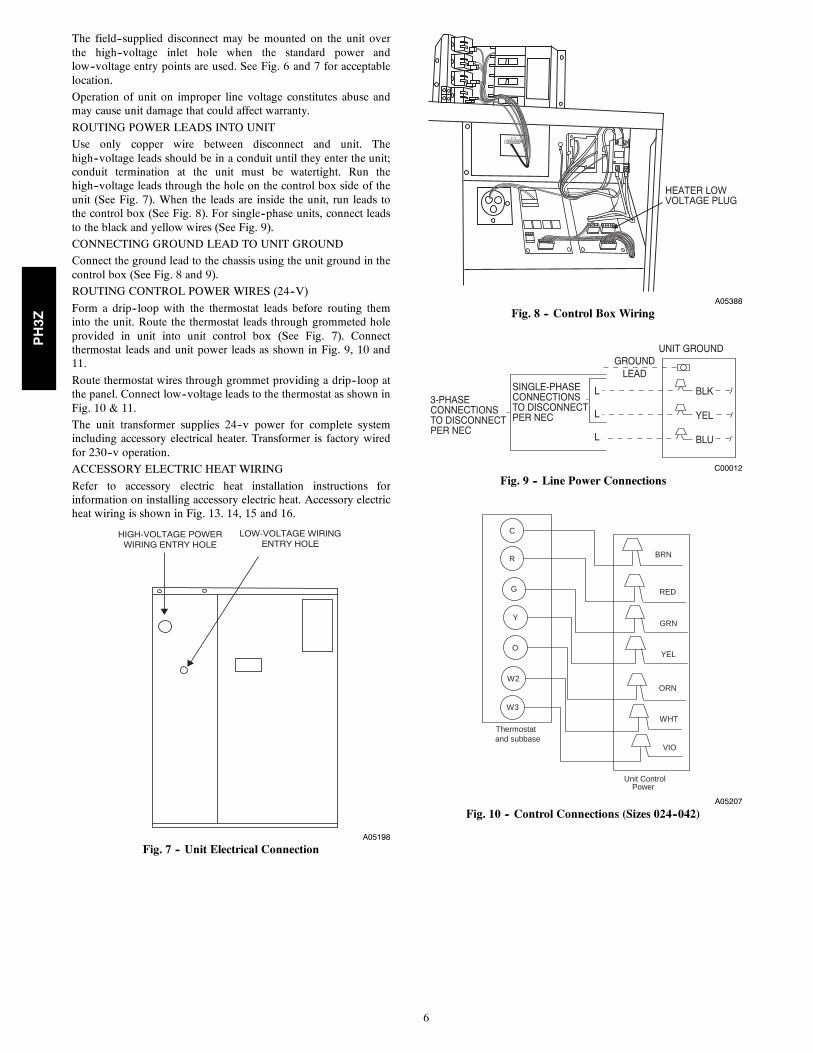
ROUTING POWER LEADS INTO UNIT
Use only copper wire between disconnect and unit. Thehigh--voltage leads should be in a conduit until they enter the unit;conduit termination at the unit must be watertight. Run thehigh--voltage leads through the hole on the control box side of theunit (See Fig. 7). When the leads are inside the unit, run leads tothe control box (See Fig. 8). For single--phase units, connect leadsto the black and yellow wires (See Fig. 9).
CONNECTING GROUND LEAD TO UNIT GROUND
Connect the ground lead to the chassis using the unit ground in thecontrol box (See Fig. 8 and 9).
ROUTING CONTROL POWER WIRES (24--V)
Form a drip--loop with the thermostat leads before routing theminto the unit. Route the thermostat leads through grommeted holeprovided in unit into unit control box (See Fig. 7). Connectthermostat leads and unit power leads as shown in Fig. 9, 10 and11.
Route thermostat wires through grommet providing a drip--loop atthe panel. Connect low--voltage leads to the thermostat as shown inFig. 10 & 11.
The unit transformer supplies 24--v power for complete systemincluding accessory electrical heater. Transformer is factory wiredfor 230--v operation.
ACCESSORY ELECTRIC HEAT WIRING
Refer to accessory electric heat installation instructions forinformation on installing accessory electric heat. Accessory electricheat wiring is shown in Fig. 13. 14, 15 and 16.
HIGH-VOLTAGE POWERWIRING ENTRY HOLE
LOW-VOLTAGE WIRINGENTRY HOLE
A05198
Fig. 7 -- Unit Electrical Connection
HEATER LOWVOLTAGE PLUG
A05388
Fig. 8 -- Control Box Wiring
3-PHASECONNECTIONSTO DISCONNECTPER NEC
SINGLE-PHASECONNECTIONSTO DISCONNECTPER NEC
GROUNDLEAD
UNIT GROUND
BLK
YEL
BLU
L
L
L
C00012
Fig. 9 -- Line Power Connections
Thermostat
Unit Control
G
Y
W2
W3
R
RED
GRN
YELO
ORN
C
BRN
WHT
VIOand subbase
Power
A05207
Fig. 10 -- Control Connections (Sizes 024--042)
PH3Z
7
Thermostat
Unit Control
G
Y
Y1
O
R
RED
GRN
YEL
W2
PNK
W3ORN
WHT
VIO
CBRN
Power
and subbase
A05208
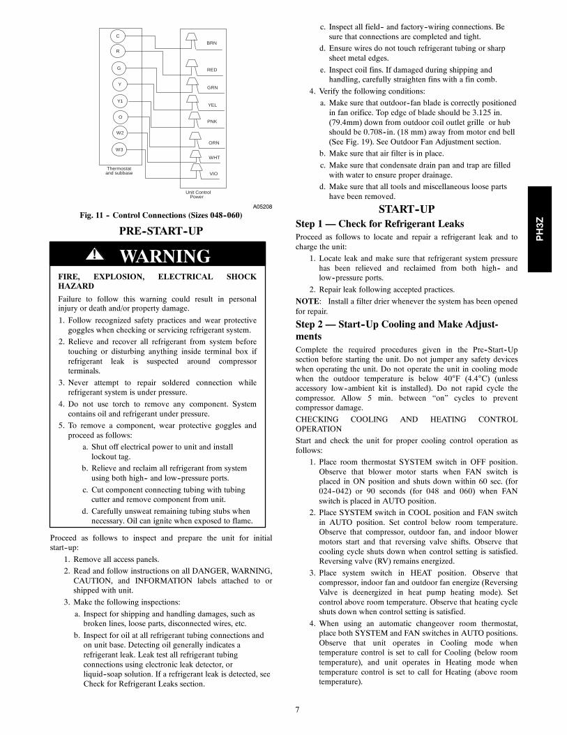
Fig. 11 -- Control Connections (Sizes 048--060)
PRE--START--UP
FIRE, EXPLOSION, ELECTRICAL SHOCKHAZARD
Failure to follow this warning could result in personalinjury or death and/or property damage.
1. Follow recognized safety practices and wear protectivegoggles when checking or servicing refrigerant system.
2. Relieve and recover all refrigerant from system beforetouching or disturbing anything inside terminal box ifrefrigerant leak is suspected around compressorterminals.
3. Never attempt to repair soldered connection whilerefrigerant system is under pressure.
4. Do not use torch to remove any component. Systemcontains oil and refrigerant under pressure.
5. To remove a component, wear protective goggles andproceed as follows:
a. Shut off electrical power to unit and installlockout tag.
b. Relieve and reclaim all refrigerant from systemusing both high-- and low--pressure ports.
c. Cut component connecting tubing with tubingcutter and remove component from unit.
d. Carefully unsweat remaining tubing stubs whennecessary. Oil can ignite when exposed to flame.
! WARNING
Proceed as follows to inspect and prepare the unit for initialstart--up:
1. Remove all access panels.
2. Read and follow instructions on all DANGER, WARNING,CAUTION, and INFORMATION labels attached to orshipped with unit.
3. Make the following inspections:
a. Inspect for shipping and handling damages, such asbroken lines, loose parts, disconnected wires, etc.
b. Inspect for oil at all refrigerant tubing connections andon unit base. Detecting oil generally indicates arefrigerant leak. Leak test all refrigerant tubingconnections using electronic leak detector, orliquid--soap solution. If a refrigerant leak is detected, seeCheck for Refrigerant Leaks section.
c. Inspect all field-- and factory--wiring connections. Besure that connections are completed and tight.
d. Ensure wires do not touch refrigerant tubing or sharpsheet metal edges.
e. Inspect coil fins. If damaged during shipping andhandling, carefully straighten fins with a fin comb.
4. Verify the following conditions:
a. Make sure that outdoor--fan blade is correctly positionedin fan orifice. Top edge of blade should be 3.125 in.(79.4mm) down from outdoor coil outlet grille or hubshould be 0.708--in. (18 mm) away from motor end bell(See Fig. 19). See Outdoor Fan Adjustment section.
b. Make sure that air filter is in place.
c. Make sure that condensate drain pan and trap are filledwith water to ensure proper drainage.
d. Make sure that all tools and miscellaneous loose partshave been removed.
START--UPStep 1 — Check for Refrigerant LeaksProceed as follows to locate and repair a refrigerant leak and tocharge the unit:
1. Locate leak and make sure that refrigerant system pressurehas been relieved and reclaimed from both high-- andlow--pressure ports.
2. Repair leak following accepted practices.
NOTE: Install a filter drier whenever the system has been openedfor repair.
Step 2 — Start--Up Cooling and Make Adjust-mentsComplete the required procedures given in the Pre--Start--Upsection before starting the unit. Do not jumper any safety deviceswhen operating the unit. Do not operate the unit in cooling modewhen the outdoor temperature is below 40°F (4.4°C) (unlessaccessory low--ambient kit is installed). Do not rapid cycle thecompressor. Allow 5 min. between “on” cycles to preventcompressor damage.
CHECKING COOLING AND HEATING CONTROLOPERATION
Start and check the unit for proper cooling control operation asfollows:
1. Place room thermostat SYSTEM switch in OFF position.Observe that blower motor starts when FAN switch isplaced in ON position and shuts down within 60 sec. (for024--042) or 90 seconds (for 048 and 060) when FANswitch is placed in AUTO position.
2. Place SYSTEM switch in COOL position and FAN switchin AUTO position. Set control below room temperature.Observe that compressor, outdoor fan, and indoor blowermotors start and that reversing valve shifts. Observe thatcooling cycle shuts down when control setting is satisfied.Reversing valve (RV) remains energized.
3. Place system switch in HEAT position. Observe thatcompressor, indoor fan and outdoor fan energize (ReversingValve is deenergized in heat pump heating mode). Setcontrol above room temperature. Observe that heating cycleshuts down when control setting is satisfied.
4. When using an automatic changeover room thermostat,place both SYSTEM and FAN switches in AUTO positions.Observe that unit operates in Cooling mode whentemperature control is set to call for Cooling (below roomtemperature), and unit operates in Heating mode whentemperature control is set to call for Heating (above roomtemperature).
PH3Z

8
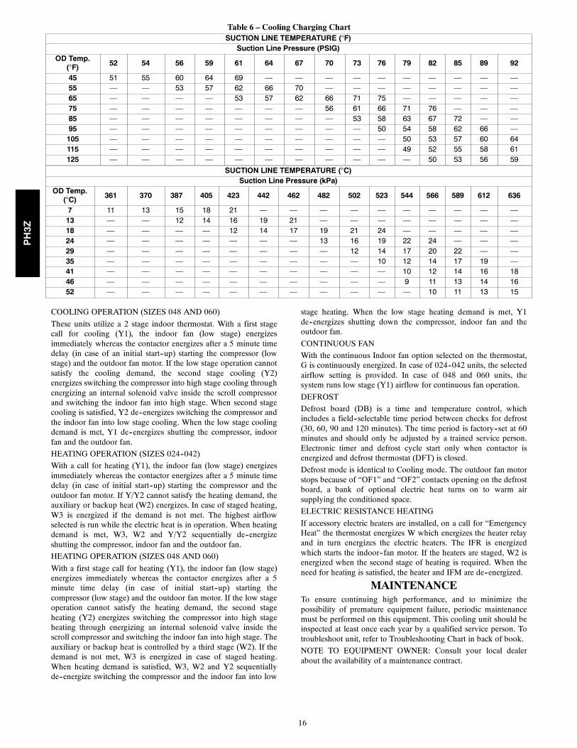
Table 3 – Required SubcoolingREQUIRED SUBCOOLING °F (°C)
Model SizeOutdoor Ambient Temperature
75 (24) 82 (28) 85 (29) 95 (35) 105 (41)048 17.5 (9.7) 17 (9.4) 16.5 (9.2) 16 (8.9) 14 (7.8)060 21 (11.7) 20.5 (11.4) 20 (11.1) 19 (10.6) 16 (8.9)
Table 4 – Required Liquid Line TemperatureREQUIRED LIQUID LINE TEMPERATURE FOR A SPECIFIC SUBCOOLING (R---22)
Pressure PSIGRequired Subcooling (°F)
Pressure (kPa)Required Subcooling (°C)
5 10 15 20 3 6 8 11
134 71 66 61 56 924 24 22 19 16
141 74 69 64 59 972 26 23 21 18
156 80 75 70 65 1075 30 27 24 21
163 83 78 73 68 1124 31 28 26 23
170 86 81 76 71 1172 33 30 27 24
177 89 84 79 74 1220 34 31 29 26
184 91 86 81 76 1268 36 33 30 27
191 94 89 84 79 1317 37 34 31 29
198 96 91 86 81 1365 38 36 33 30
205 98 93 88 83 1413 40 37 34 31
213 101 96 91 86 1468 41 38 36 33
221 104 99 94 89 1524 43 40 37 34
229 106 101 96 91 1579 44 41 38 36
237 108 103 98 93 1634 45 42 40 37
245 111 106 101 96 1689 47 44 41 38
253 113 108 103 98 1744 48 45 42 40
262 116 111 106 101 1806 49 46 44 41
271 118 113 108 103 1868 51 48 45 42
280 121 116 111 106 1930 52 49 46 44
289 123 118 113 108 1992 53 51 48 45
298 125 120 115 110 2054 55 52 49 46
307 128 123 118 113 2116 56 53 50 48
317 130 125 120 115 2185 57 54 52 49
327 132 127 122 117 2254 59 56 53 50
337 135 130 125 120 2323 60 57 54 52
347 137 132 127 122 2392 61 58 56 53
357 139 134 129 124 2461 62 60 57 54
367 142 137 132 127 2530 64 61 58 55
Step 3 — Refrigerant ChargeRefrigerant Charge — Amount of refrigerant charge is listed onunit nameplate and in Table 1. Refer to Payne Refrigerant ServiceTechniques Manual, Refrigerants section. Unit panels must be inplace when unit is operating during charging procedure. Unit mustoperate a minimum of 15 minutes before checking charge.
NO CHARGE
Refer to Payne Refrigerant Service Techniques. Use standardevacuating techniques. After evacuating system, weigh in thespecified amount of refrigerant (refer to Table 1).
LOW CHARGE COOLING
024--042 units:1. Measure suction line pressure by attaching a gauge to theservice port.
2. Measure the suction line temperature by attaching atemperature sensing device to it.
3. Insulate the temperature sensing device so that the outdoorambient doesn’t affect the reading.
4. Locate the measured suction line pressure in the top row ofTable 6 and the measured outdoor ambient temperature inthe left column of the table. Based on the two values,determine the required suction line temperature.
5. If the measured suction line temperature is greater than thetabulated temperature, add charge in the system.
048 and 060 units:1. Measure discharge line pressure by attaching a gauge to theservice port.
2. Measure the liquid line temperature by attaching atemperature sensing device to it.
3. Insulate the temperature sensing device so that the outdoorambient doesn’t affect the reading.
4. Refer to the required subcooling in Tables 3 and 4 to findthe required subcooling based on the model size and theoutdoor ambient temperature.
5. Interpolate if the outdoor temperature lies in between thetable values. Extrapolate if the temperature lies beyond thetable range.
PH3Z
9
6. Find the pressure value corresponding to the measuredpressure on the compressor discharge line.
7. Read across from the pressure reading to obtain the liquidline temperature for a required subcooling.
8. Add charge if the measured temperature is higher than theliquid line temperature value in the table.
9. Add charge using the service connection on the suction lineof the compressor.
HEATING MODE CHARGE
Do not attempt to adjust charge by cooling methods while in heatpump heating mode. Recover refrigerant and weigh in according tounit data plate refrigerant data.
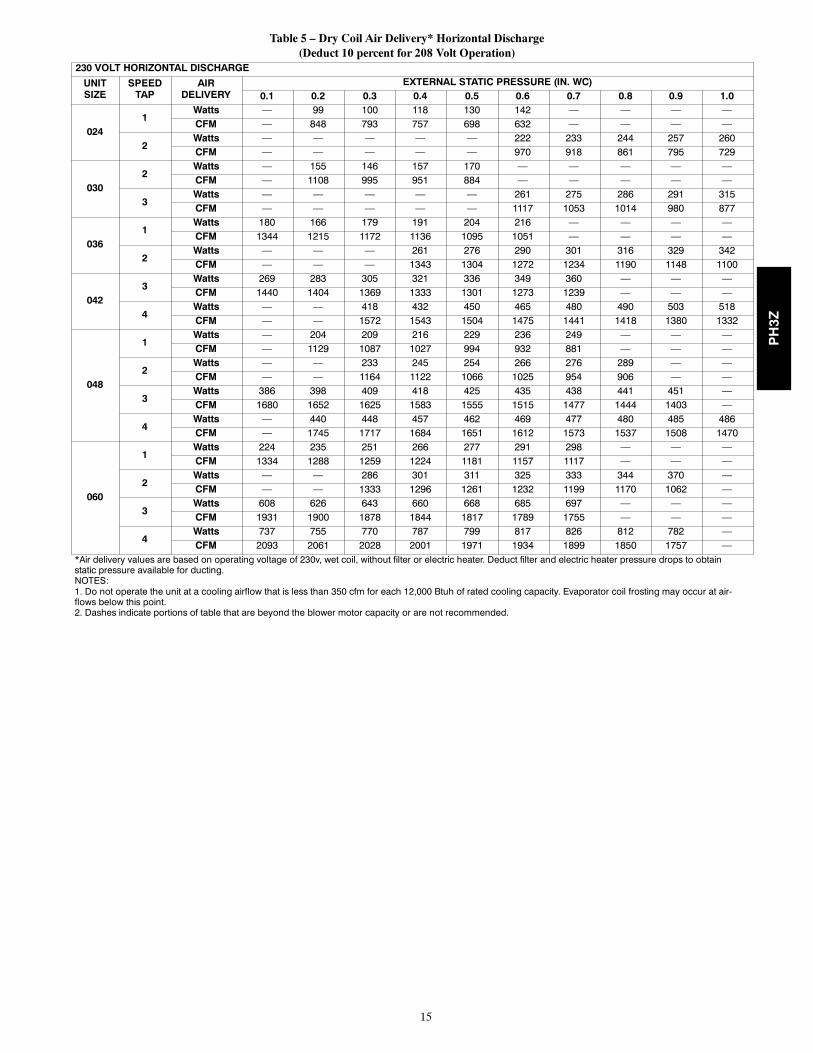
Step 4 — Indoor Airflow and Airflow Adjust-mentsNOTE: For cooling operation, the recommended airflow is 350to 450 cfm for each 12,000 Btuh of rated cooling capacity.
Table 5 shows dry coil air delivery for horizontal discharge units.Tables 7--9 show pressure drops.
NOTE: Be sure that all supply-- and return--air grilles are open,free from obstructions, and adjusted properly.
ELECTRICAL SHOCK HAZARD
Failure to follow this warning could result in personalinjury or death.
Disconnect electrical power to the unit and install lockouttag before changing blower speed.
! WARNING
Airflow can be changed by changing the lead connections at theblower motor. To change motor speeds, reposition wire at fanmotor speed terminals labeled 1--2--3--4 (refer to Fig. 12).
Remove the speed tap connector labeled 1 through 5 and themotor. While looking at the connector end that is inserted into themotor, gently pry the locking tab outward and remove the wirefrom the connector. Insert the wire into the desired tap until it locksinto place. Be sure new airflow meets the range noted above andminimum electic heat CFM, if equipped. Refer to Table 2 and 5.
All model sizes are factory wired for rated airflow operation.
A08210
Fig. 12 -- Motor Speed Selection
FOR 208/230V BLOWER MOTORS
The motor lead speed connections are as follows:SIZE RATED AIRFLOW HIGH AIRFLOW024 Tap 1 Tap 3030 Tap 2 Tap 4036 Tap 1 Tap 3042 Tap 2 Tap 4
SIZERATED AIRFLOW HIGH AIRFLOW
Low Stage High Stage Low Stage High Stage048 Tap 1 Tap 3 Tap 2 Tap 4060 Tap 1 Tap 3 Tap 2 Tap 4
Step 5 — Unit ControlsAll compressors have the following internal--protection controls.
HIGH--PRESSURE RELIEF VALVE
This valve opens when the pressure differential between the lowand high side becomes excessive.
LOSS OF CHARGE SWITCH
Located on the outdoor liquid line is a low--pressure switch whichfunctions as a loss--of--charge switch. This switch contains aSchrader core depressor. This switch opens at 7 psig and closes at22 psig. No adjustment is necessary.
COMPRESSOR OVERLOAD
This overload interrupts power to the compressor when either thecurrent or internal temperature become excessive, andautomatically resets when the internal temperature drops to a safelevel.
This overload may require up to 60 minutes (or longer) to reset;therefore, if the internal overload is suspected of being open,disconnect the electrical power to the unit and check the circuitthrough the overload with an ohmmeter or continuity tester.
Step 6 — Compressor RotationOn 3--Phase units it is important to be certain compressor isrotating in the proper direction. To determine whether or notcompressor is rotating in the proper direction:
1. Connect service gauges to suction and discharge pressurefittings.
2. Energize the compressor.
3. The suction pressure should drop and the discharge pressureshould rise, as is normal on any start--up.
If the suction pressure does not drop and the discharge pressuredoes not rise to normal levels:
1. Turn off power to the unit and tag disconnect.
2. Reverse any two of the unit power leads.
3. Turn on power to the unit.
The suction and discharge pressure levels should now move totheir normal start--up levels.
NOTE: When the compressor is rotating in the wrong direction,the unit makes an elevated level of noise and does not providecooling.
Step 7 — Sequence of OperationFAN OPERATION
The FAN switch on the thermostat controls indoor fan operation.When the FAN switch is placed in the ON position, the IFR(indoor--fan relay) is energized through the G terminal on thethermostat. The normally--open contacts close, which then providepower to the indoor (evaporator) fan motor (IFM). The IFM willrun continuously when the FAN switch is set to ON.
When the FAN switch is set to AUTO, the thermostat deenergizesthe IFR (provided there is not a call for cooling). The contacts openand the IFM is deenergized. The IFM will be energized only whenthere is a call for cooling, in heat pump heating mode or if the unitis equipped with accessory electric heat, the indoor--fan motor willalso run while the accessory electric heat is energized.
NOTE: Some units are equipped with a time--delay relay. Onthese units, the indoor fan remains on for 30 seconds after G or Yis deenergized.
COOLING OPERATION (SIZES 024--042)
With a call for cooling (Y/Y2), the indoor fan energizesimmediately whereas the contactor energizes after a 5 minute timedelay (in case of initial start--up) starting the compressor and theoutdoor fan motor. When the cooling demand is met, Y/Y2de--energizes, shutting the compressor, indoor fan and the outdoorfan.
PH3Z
10
A08209
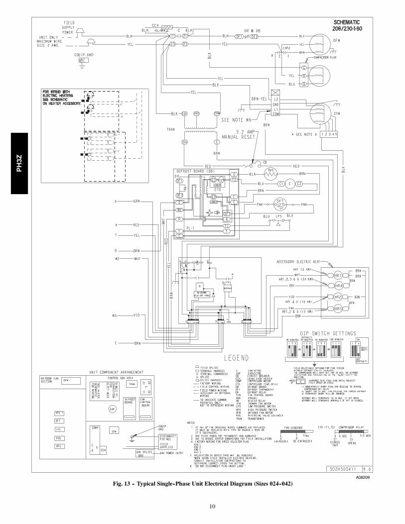
Fig. 13 -- Typical Single--Phase Unit Electrical Diagram (Sizes 024--042)
PH3Z

11
A0640
Fig. 14 -- Typical Single--Phase Unit Electrical Diagram (Sizes 048--060)
PH3Z
12
A06325
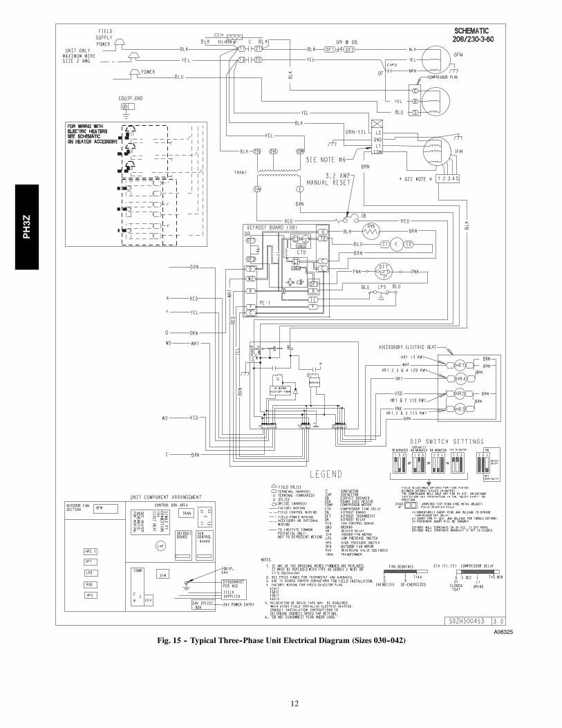
Fig. 15 -- Typical Three--Phase Unit Electrical Diagram (Sizes 030--042)
PH3Z
13
A06326
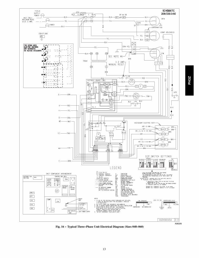
Fig. 16 -- Typical Three--Phase Unit Electrical Diagram (Sizes 048--060)
PH3Z
14
A08211
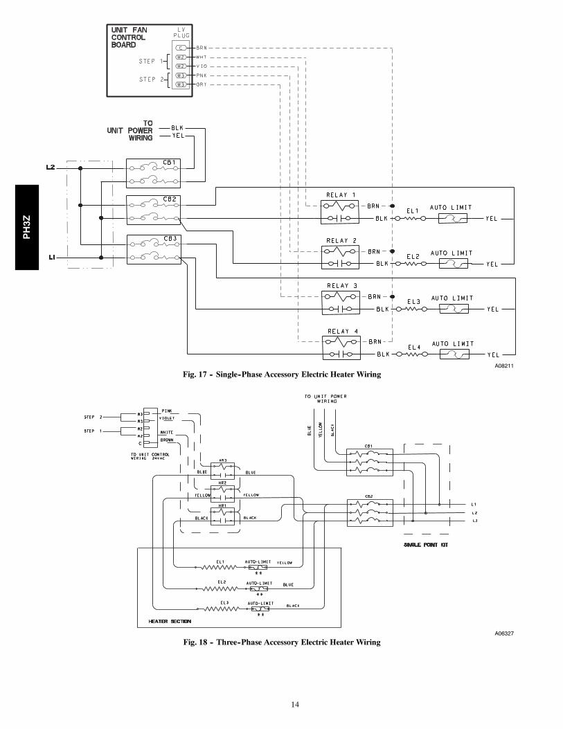
Fig. 17 -- Single--Phase Accessory Electric Heater Wiring
A06327
Fig. 18 -- Three--Phase Accessory Electric Heater Wiring
PH3Z
15
Table 5 – Dry Coil Air Delivery* Horizontal Discharge(Deduct 10 percent for 208 Volt Operation)
230 VOLT HORIZONTAL DISCHARGE
UNITSIZE
SPEEDTAP
AIRDELIVERY
EXTERNAL STATIC PRESSURE (IN. WC)0.1 0.2 0.3 0.4 0.5 0.6 0.7 0.8 0.9 1.0
0241
Watts — 99 100 118 130 142 — — — —CFM — 848 793 757 698 632 — — — —
2Watts — — — — — 222 233 244 257 260CFM — — — — — 970 918 861 795 729
0302
Watts — 155 146 157 170 — — — — —CFM — 1108 995 951 884 — — — — —
3Watts — — — — — 261 275 286 291 315CFM — — — — — 1117 1053 1014 980 877
0361
Watts 180 166 179 191 204 216 — — — —CFM 1344 1215 1172 1136 1095 1051 — — — —
2Watts — — — 261 276 290 301 316 329 342CFM — — — 1343 1304 1272 1234 1190 1148 1100
0423
Watts 269 283 305 321 336 349 360 — — —CFM 1440 1404 1369 1333 1301 1273 1239 — — —
4Watts — — 418 432 450 465 480 490 503 518CFM — — 1572 1543 1504 1475 1441 1418 1380 1332
048
1Watts — 204 209 216 229 236 249 — — —CFM — 1129 1087 1027 994 932 881 — — —
2Watts — — 233 245 254 266 276 289 — —CFM — — 1164 1122 1066 1025 954 906 — —
3Watts 386 398 409 418 425 435 438 441 451 —CFM 1680 1652 1625 1583 1555 1515 1477 1444 1403 —
4Watts — 440 448 457 462 469 477 480 485 486CFM — 1745 1717 1684 1651 1612 1573 1537 1508 1470
060
1Watts 224 235 251 266 277 291 298 — — —CFM 1334 1288 1259 1224 1181 1157 1117 — — —
2Watts — — 286 301 311 325 333 344 370 —CFM — — 1333 1296 1261 1232 1199 1170 1062 —
3Watts 608 626 643 660 668 685 697 — — —CFM 1931 1900 1878 1844 1817 1789 1755 — — —
4Watts 737 755 770 787 799 817 826 812 782 —CFM 2093 2061 2028 2001 1971 1934 1899 1850 1757 —
*Air delivery values are based on operating voltage of 230v, wet coil, without filter or electric heater. Deduct filter and electric heater pressure drops to obtainstatic pressure available for ducting.NOTES:1. Do not operate the unit at a cooling airflow that is less than 350 cfm for each 12,000 Btuh of rated cooling capacity. Evaporator coil frosting may occur at air-flows below this point.2. Dashes indicate portions of table that are beyond the blower motor capacity or are not recommended.
PH3Z
16
Table 6 – Cooling Charging ChartSUCTION LINE TEMPERATURE (°F)
Suction Line Pressure (PSIG)OD Temp.
(°F) 52 54 56 59 61 64 67 70 73 76 79 82 85 89 92
45 51 55 60 64 69 — — — — — — — — — —55 — — 53 57 62 66 70 — — — — — — — —65 — — — — 53 57 62 66 71 75 — — — — —75 — — — — — — — 56 61 66 71 76 — — —85 — — — — — — — — 53 58 63 67 72 — —95 — — — — — — — — — 50 54 58 62 66 —105 — — — — — — — — — — 50 53 57 60 64115 — — — — — — — — — — 49 52 55 58 61125 — — — — — — — — — — — 50 53 56 59
SUCTION LINE TEMPERATURE (°C)Suction Line Pressure (kPa)
OD Temp.(°C) 361 370 387 405 423 442 462 482 502 523 544 566 589 612 636
7 11 13 15 18 21 — — — — — — — — — —13 — — 12 14 16 19 21 — — — — — — — —18 — — — — 12 14 17 19 21 24 — — — — —24 — — — — — — — 13 16 19 22 24 — — —29 — — — — — — — — 12 14 17 20 22 — —35 — — — — — — — — — 10 12 14 17 19 —41 — — — — — — — — — — 10 12 14 16 1846 — — — — — — — — — — 9 11 13 14 1652 — — — — — — — — — — — 10 11 13 15
COOLING OPERATION (SIZES 048 AND 060)
These units utilize a 2 stage indoor thermostat. With a first stagecall for cooling (Y1), the indoor fan (low stage) energizesimmediately whereas the contactor energizes after a 5 minute timedelay (in case of an initial start--up) starting the compressor (lowstage) and the outdoor fan motor. If the low stage operation cannotsatisfy the cooling demand, the second stage cooling (Y2)energizes switching the compressor into high stage cooling throughenergizing an internal solenoid valve inside the scroll compressorand switching the indoor fan into high stage. When second stagecooling is satisfied, Y2 de--energizes switching the compressor andthe indoor fan into low stage cooling. When the low stage coolingdemand is met, Y1 de--energizes shutting the compressor, indoorfan and the outdoor fan.
HEATING OPERATION (SIZES 024--042)
With a call for heating (Y1), the indoor fan (low stage) energizesimmediately whereas the contactor energizes after a 5 minute timedelay (in case of initial start--up) starting the compressor and theoutdoor fan motor. If Y/Y2 cannot satisfy the heating demand, theauxiliary or backup heat (W2) energizes. In case of staged heating,W3 is energized if the demand is not met. The highest airflowselected is run while the electric heat is in operation. When heatingdemand is met, W3, W2 and Y/Y2 sequentially de--energizeshutting the compressor, indoor fan and the outdoor fan.
HEATING OPERATION (SIZES 048 AND 060)
With a first stage call for heating (Y1), the indoor fan (low stage)energizes immediately whereas the contactor energizes after a 5minute time delay (in case of initial start--up) starting thecompressor (low stage) and the outdoor fan motor. If the low stageoperation cannot satisfy the heating demand, the second stageheating (Y2) energizes switching the compressor into high stageheating through energizing an internal solenoid valve inside thescroll compressor and switching the indoor fan into high stage. Theauxiliary or backup heat is controlled by a third stage (W2). If thedemand is not met, W3 is energized in case of staged heating.When heating demand is satisfied, W3, W2 and Y2 sequentiallyde--energize switching the compressor and the indoor fan into low
stage heating. When the low stage heating demand is met, Y1de--energizes shutting down the compressor, indoor fan and theoutdoor fan.
CONTINUOUS FAN
With the continuous Indoor fan option selected on the thermostat,G is continuously energized. In case of 024--042 units, the selectedairflow setting is provided. In case of 048 and 060 units, thesystem runs low stage (Y1) airflow for continuous fan operation.
DEFROST
Defrost board (DB) is a time and temperature control, whichincludes a field--selectable time period between checks for defrost(30, 60, 90 and 120 minutes). The time period is factory--set at 60minutes and should only be adjusted by a trained service person.Electronic timer and defrost cycle start only when contactor isenergized and defrost thermostat (DFT) is closed.
Defrost mode is identical to Cooling mode. The outdoor fan motorstops because of “OF1” and “OF2” contacts opening on the defrostboard, a bank of optional electric heat turns on to warm airsupplying the conditioned space.
ELECTRIC RESISTANCE HEATING
If accessory electric heaters are installed, on a call for “EmergencyHeat” the thermostat energizes W which energizes the heater relayand in turn energizes the electric heaters. The IFR is energizedwhich starts the indoor--fan motor. If the heaters are staged, W2 isenergized when the second stage of heating is required. When theneed for heating is satisfied, the heater and IFM are de--energized.
MAINTENANCETo ensure continuing high performance, and to minimize thepossibility of premature equipment failure, periodic maintenancemust be performed on this equipment. This cooling unit should beinspected at least once each year by a qualified service person. Totroubleshoot unit, refer to Troubleshooting Chart in back of book.
NOTE TO EQUIPMENT OWNER: Consult your local dealerabout the availability of a maintenance contract.
PH3Z
17
PERSONAL INJURY AND UNIT DAMAGEHAZARD
Failure to follow this warning could result in personalinjury or death and possible unit component damage.
The ability to properly perform maintenance on thisequipment requires certain expertise, mechanical skills,tools and equipment. If you do not possess these, do notattempt to perform any maintenance on this equipment,other than those procedures recommended in the Owner’sManual.
! WARNING
The minimum maintenance requirements for this equipment are asfollows:
1. Inspect air filter(s) each month. Clean or replace whennecessary.
2. Inspect indoor coil, drain pan, and condensate drain eachcooling season for cleanliness. Clean when necessary.
3. Inspect blower motor and wheel for cleanliness eachcooling season. Clean when necessary.
4. Check electrical connections for tightness and controls forproper operation each cooling season. Service whennecessary.
5. Ensure electric wires are not in contact with refrigeranttubing or sharp metal edges.
ELECTRICAL SHOCK HAZARD
Failure to follow these warnings could result in personalinjury or death:
1. Turn off electrical power to the unit before performingany maintenance or service on this unit.
2. Use extreme caution when removing panels and parts.
3. Never place anything combustible either on or in contactwith the unit.
! WARNING
Step 1 — Air FilterIMPORTANT: Never operate the unit without a suitable air filterin the return--air duct system. Always replace the filter with thesame dimensional size and type as originally installed. See Table 1for recommended filter sizes.
Inspect air filter(s) at least once each month and replace(throwaway--type) or clean (cleanable--type) at least twice duringeach cooling season and twice during the heating season, orwhenever the filter becomes clogged with dust and lint.
Step 2 — Unit Top Removal (Outdoor--Coil Side)NOTE: When performing maintenance or service procedures thatrequire removal of the unit top, be sure to perform all of the routinemaintenance procedures that require top removal, including coilinspection and cleaning, and condensate drain pan inspection andcleaning.
ELECTRICAL SHOCK HAZARD
Failure to follow this warning could result in personalinjury or death.
Disconnect and tag electrical power to the unit beforeremoving top.
! WARNING
Only qualified service personnel should perform maintenance andservice procedures that require unit top removal.
Refer to the following top removal procedures:
1. Remove screws on unit top cover surface. (Save all screws.)
2. Remove screws on unit top cover flange. (Save all screws.)
3. Lift top from unit carefully. Set top on edge and make surethat top is supported by unit side that is opposite duct (orplenum) side.
4. Carefully replace and secure unit top to unit, using screwsremoved in 1 and 2 above, when maintenance and/orservice procedures are completed.
Step 3 — Indoor Blower and MotorFor longer life, operating economy, and continuing efficiency,clean accumulated dirt and grease from the blower wheel andmotor annually.
ELECTRICAL SHOCK HAZARD
Failure to follow this warning could result in personalinjury or death.
Disconnect and tag electrical power to the unit beforecleaning and lubricating the blower motor and wheel.
! WARNING
To clean the blower wheel:
1. Remove the blower housing:
a. Remove the screws on the external side of the ductpanel that fasten the housing to the duct panel assembly.
b. Remove the side access panel and unscrew themounting bracket that fastens the blower housing to theinternal partition panel fo the control box assembly.
c. Make sure that the blower housing is supported by handbefore completely removing the mounting bracket.
d. Slide the blower housing from the rails of the duct paneland place it outside the unit.
2. Remove the blower wheel from the housing:
a. Loosen the set screw which secures the wheel to themotor shaft.
b. Loosen the three mounting legs of the motor byremoving the bolts that fasten themounting legs to thehousing.
c. Slide out the motor assembly (motor, belly band and the3 mounting legs) from the hub of the wheel.
d. Remove the filler panel at the discharge end of theblower housing by removing the two screws that fastenit to the housing.
e. Remove the wheel form the housing.
3. Remove the caked on dirt from the wheel and the motorusing a brush.
4. Remove lint and dirt accumulations from the wheel andhousing with a vacuum cleaner, using a soft brushattachment.
5. Remove grease and oil with a mild solvent.
6. Reassemble as follows:
a. Slip the wheel back in the housing with the hub setscrew parented in the correct direction.
b. Install the filler panel.
c. Reinsert the motor assembly in the wheel hub and alignthe mounting legs with the housing mounting holdlocations.
d. Tighten the mounting bolts to fasten the motor assemblywith the housing.
PH3Z
18
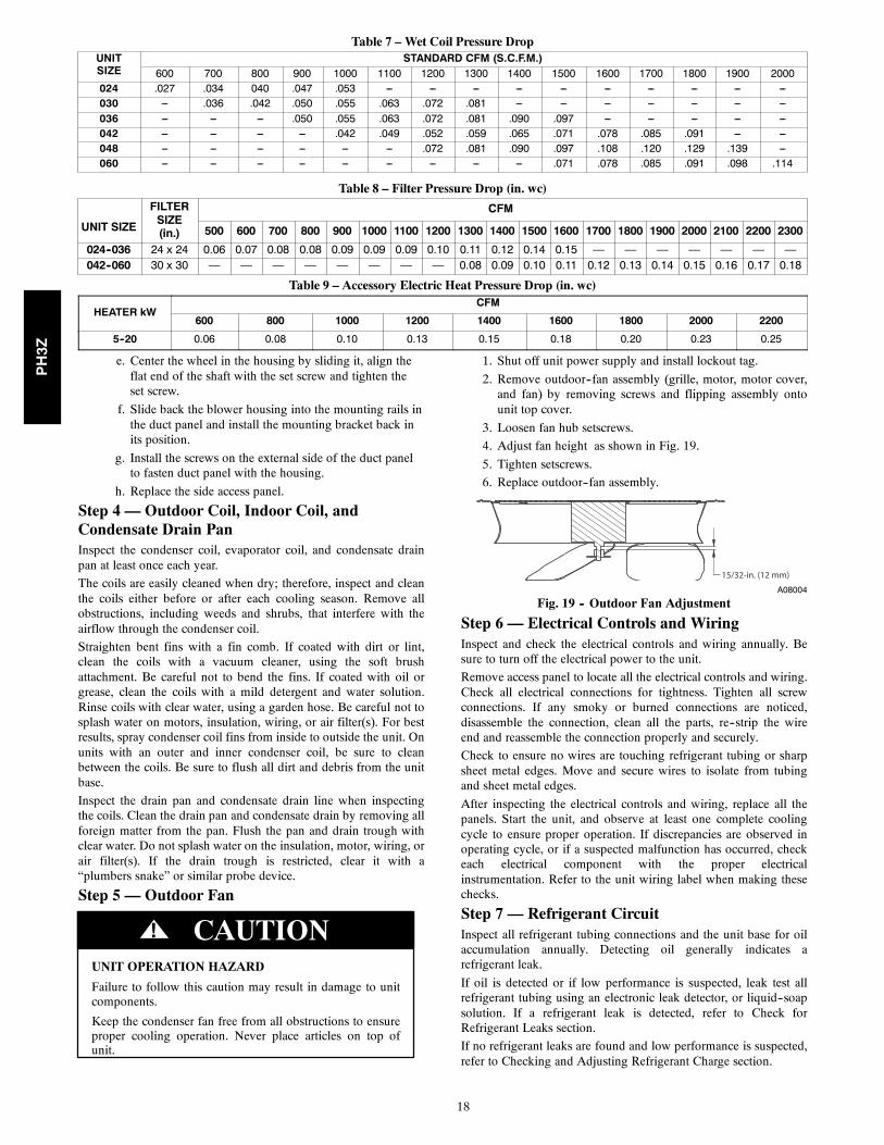
Table 7 – Wet Coil Pressure DropUNITSIZE
STANDARD CFM (S.C.F.M.)600 700 800 900 1000 1100 1200 1300 1400 1500 1600 1700 1800 1900 2000
024 .027 .034 040 .047 .053 --- --- --- --- --- --- --- --- --- ---030 --- .036 .042 .050 .055 .063 .072 .081 --- --- --- --- --- --- ---036 --- --- --- .050 .055 .063 .072 .081 .090 .097 --- --- --- --- ---042 --- --- --- --- .042 .049 .052 .059 .065 .071 .078 .085 .091 --- ---048 --- --- --- --- --- --- .072 .081 .090 .097 .108 .120 .129 .139 ---060 --- --- --- --- --- --- --- --- --- .071 .078 .085 .091 .098 .114
Table 8 – Filter Pressure Drop (in. wc)
UNIT SIZE
FILTERSIZE(in.)
CFM
500 600 700 800 900 1000 1100 1200 1300 1400 1500 1600 1700 1800 1900 2000 2100 2200 2300
024--036 24 x 24 0.06 0.07 0.08 0.08 0.09 0.09 0.09 0.10 0.11 0.12 0.14 0.15 — — — — — — —042--060 30 x 30 — — — — — — — — 0.08 0.09 0.10 0.11 0.12 0.13 0.14 0.15 0.16 0.17 0.18
Table 9 – Accessory Electric Heat Pressure Drop (in. wc)
HEATER kWCFM
600 800 1000 1200 1400 1600 1800 2000 2200
5--20 0.06 0.08 0.10 0.13 0.15 0.18 0.20 0.23 0.25
e. Center the wheel in the housing by sliding it, align theflat end of the shaft with the set screw and tighten theset screw.
f. Slide back the blower housing into the mounting rails inthe duct panel and install the mounting bracket back inits position.
g. Install the screws on the external side of the duct panelto fasten duct panel with the housing.
h. Replace the side access panel.
Step 4 — Outdoor Coil, Indoor Coil, andCondensate Drain PanInspect the condenser coil, evaporator coil, and condensate drainpan at least once each year.
The coils are easily cleaned when dry; therefore, inspect and cleanthe coils either before or after each cooling season. Remove allobstructions, including weeds and shrubs, that interfere with theairflow through the condenser coil.
Straighten bent fins with a fin comb. If coated with dirt or lint,clean the coils with a vacuum cleaner, using the soft brushattachment. Be careful not to bend the fins. If coated with oil orgrease, clean the coils with a mild detergent and water solution.Rinse coils with clear water, using a garden hose. Be careful not tosplash water on motors, insulation, wiring, or air filter(s). For bestresults, spray condenser coil fins from inside to outside the unit. Onunits with an outer and inner condenser coil, be sure to cleanbetween the coils. Be sure to flush all dirt and debris from the unitbase.
Inspect the drain pan and condensate drain line when inspectingthe coils. Clean the drain pan and condensate drain by removing allforeign matter from the pan. Flush the pan and drain trough withclear water. Do not splash water on the insulation, motor, wiring, orair filter(s). If the drain trough is restricted, clear it with a“plumbers snake” or similar probe device.
Step 5 — Outdoor Fan
UNIT OPERATION HAZARD
Failure to follow this caution may result in damage to unitcomponents.
Keep the condenser fan free from all obstructions to ensureproper cooling operation. Never place articles on top ofunit.
CAUTION!
1. Shut off unit power supply and install lockout tag.
2. Remove outdoor--fan assembly (grille, motor, motor cover,and fan) by removing screws and flipping assembly ontounit top cover.
3. Loosen fan hub setscrews.
4. Adjust fan height as shown in Fig. 19.
5. Tighten setscrews.
6. Replace outdoor--fan assembly.
15/32-in. (12 mm)
A08004
Fig. 19 -- Outdoor Fan Adjustment
Step 6 — Electrical Controls and WiringInspect and check the electrical controls and wiring annually. Besure to turn off the electrical power to the unit.
Remove access panel to locate all the electrical controls and wiring.Check all electrical connections for tightness. Tighten all screwconnections. If any smoky or burned connections are noticed,disassemble the connection, clean all the parts, re--strip the wireend and reassemble the connection properly and securely.
Check to ensure no wires are touching refrigerant tubing or sharpsheet metal edges. Move and secure wires to isolate from tubingand sheet metal edges.
After inspecting the electrical controls and wiring, replace all thepanels. Start the unit, and observe at least one complete coolingcycle to ensure proper operation. If discrepancies are observed inoperating cycle, or if a suspected malfunction has occurred, checkeach electrical component with the proper electricalinstrumentation. Refer to the unit wiring label when making thesechecks.
Step 7 — Refrigerant CircuitInspect all refrigerant tubing connections and the unit base for oilaccumulation annually. Detecting oil generally indicates arefrigerant leak.
If oil is detected or if low performance is suspected, leak test allrefrigerant tubing using an electronic leak detector, or liquid--soapsolution. If a refrigerant leak is detected, refer to Check forRefrigerant Leaks section.
If no refrigerant leaks are found and low performance is suspected,refer to Checking and Adjusting Refrigerant Charge section.
PH3Z
19
Step 8 — Indoor AirflowThe heating and/or cooling airflow does not require checkingunless improper performance is suspected. If a problem exists, besure that all supply-- and return--air grilles are open and free fromobstructions, and that the air filter is clean.
Step 9 — Metering DevicesRefrigerant cooling metering device is an AccuRater (024--042) orTXV (048 and 060) located upstream of the indoor coil distributorassembly. Refrigerant heating mode metering device is anAccuRater located upstrem of the outdoor coil distributorassembly.
Step 10 — Liquid Line StrainersThe liquid line strainers (to protect metering devices) are made ofwire mesh and are located in the liquid lines on the inlet side of themetering devices.
Step 11 — High Flow ValvesHigh flow valves are located on the compressor hot gas and suctiontubes. Large black plastic caps distinguish these valves withO--rings located inside the caps. These valves can not be accessedfor service in the field. Ensure the plastic caps are in place and tightor the possibility of refrigerant leakage could occur.
TROUBLESHOOTINGRefer to the Troubleshooting Chart (Table 10) for troubleshootinginformation.
START--UP CHECKLISTUse the Start--Up Checklist at the back of this manual.
PH3Z
20
STRAINER
AC
CU
MU
LAT
OR
CO
MP
RE
SS
OR
ST
RA
INE
R
LCS
OUTDOOR COIL INDOOR COIL
A
B
D
C
Check Valves
A Open
B Closed
C Open
D Closed
LEGEND
LCS Loss of Charge Switch
Acutrol Metering Device
Check Valve (Arrow indicates direction of flow)
HEATING CYCLE
1. Hot gas from compressor flows through the 4-way valve and isdirected to the cooling liquid line check valve. It is then condensedand directed through subcooling circuits and out to the strainerand the check valve in the heating liquid line.
2. The refrigerant then feeds the outdoor coil through the Acutrolmetering device on each circuit.
3. Each circuit evaporates the refrigerant and the circuits are com-bined in the outdoor header with some of the circuits flowing throughthe check valve.
4. The refrigerant then flows through the 4-way valve, accumulator,and back to the compressor.
C95045
Fig. 20 -- Typical Heat Pump Operation, Heating Mode
STRAINER
AC
CU
MU
LAT
OR
CO
MP
RE
SS
OR
ST
RA
INE
R
LCS
OUTDOOR COIL INDOOR COIL
A
B
D
C
Check Valves
A Closed
B Open
C Closed
D Open
LEGEND
LCS Loss of Charge Switch
Acutrol Metering Device
Check Valve (Arrow indicates direction of flow)
COOLING CYCLE
1. Hot gas from compressor flows through the 4-way valve and isdirected to the heating liquid line check valve. It is then con-densed and subcooled through converging circuits. Refrigerant leavesthe outdoor coil by way of the strainer and the check valve in thecooling liquid line.
2. The refrigerant then feeds the indoor coil through the Acutrolmetering device on each circuit.
3. Each circuit evaporates the refrigerant and the circuits are com-bined in the indoor coil header with some of the circuits flowingthrough the check valve.
4. The refrigerant then flows through the 4-way valve, accumulator,and back to the compressor.
C95044
Fig. 21 -- Typical Heat Pump Operation, Cooling Mode
PH3Z
21
Table 10 – Troubleshooting ChartSYMPTOM CAUSE REMEDY
Compressor and outdoor fanwill not start
Power failure Call power company
Fuse blown or circuit breaker tripped Replace fuse or reset circuit breaker
Defective contactor, transformer, control relay, orhigh--pressure, loss--of--charge or low--pressure switch
Replace component
Insufficient line voltage Determine cause and correct
Incorrect or faulty wiring Check wiring diagram and rewire correctly
Thermostat setting too low/too high Reset thermostat setting
Compressor will not start but condenser fanruns
Faulty wiring or circuitLoose connections in compressor Check wiring and repair or replace
Compressor motor burned out, seized, or Determine cause
internal overload open Replace compressor
Defective run capacitor, overload, or PTC (positivetemperature coefficient) thermistor Determine cause and replace
One leg of 3--phase power deadReplace fuse or reset circuit breakerDetermine cause
Low input voltage (20 percent low) Determine cause and correct
Three--phase scroll compressor (size 030--Scroll compressor is rotating in the wrong direction
Correct the direction of rotation by reversing the
060 unit) has a low pressure differential 3--phase power leads to the unit
Compressor cycles (other than normally sat-isfying) cooling/heating calls
Refrigerant overcharge or underchargeRecover refrigerant, evacuate system, and re-charge to capacities shown on rating plate
Defective compressor Replace and determine cause
Insufficient line voltage Determine cause and correct
Blocked outdoor coil Determine cause and correct
Defective run/start capacitor, overload or start relay Determine cause and replace
Faulty outdoor fan motor or capacitor Replace
Restriction in refrigerant system Locate restriction and remove
Compressor operates continuously
Dirty air filter Replace filter
Unit undersized for load Decrease load or increase unit size
Thermostat temperature set too low Reset thermostat setting
Low refrigerant charge Locate leak, repair, and recharge
Air in systemRecover refrigerant, evacuate system, and re-charge
Outdoor coil dirty or restricted Clean coil or remove restriction
Excessive head pressure
Dirty air filter Replace filter
Dirty indoor or outdoor coil Clean coil
Refrigerant overcharged Recover excess refrigerant
Air in systemRecover refrigerant, evacuate system, and re-charge
Indoor or outdoor air restricted or air short--cycling Determine cause and correct
Head pressure too lowLow refrigerant charge Check for leaks, repair and rechargeRestriction in liquid tube Remove restriction
Excessive suction pressureHigh Heat load Check for source and eliminateReversing valve hung up or leaking internally Replace valveRefrigerant overcharged Recover excess refrigerant
Suction pressure too low
Dirty air filter Replace filterLow refrigerant charge Check for leaks, repair and rechargeMetering device or low side restricted Remove source of restrictionInsufficient coil airflow Check filter–replace if necessaryTemperature too low in conditioned area Reset thermostat settingOutdoor ambient below 55°F (12.8°C) Install low--ambient kitFilter drier restricted Replace
PH3Z
22
START--UP CHECKLIST(REMOVE AND STORE IN JOB FILE)
I. PRELIMINARY INFORMATIONModel No ............................................................................................................................................................Serial No .............................................................................................................................................................Date .....................................................................................................................................................................Technician ..........................................................................................................................................................Customer Information(Name/Address) .....................................................................................................................
II. PRE--START--UP____ Verify that all packing materials have been removed from unit.____ Verify that condensate connection is installed per installation instructions.____ Check all electrical connections and terminals for tightness.____ Check wire proximity to refrigerant tubes and sheet metal edges.____ Check that indoor (indoor) air filter is clean and in place.____ Verify that unit installation is level.____ Check fan wheel propeller for location in housing and setscrew tightness.
III. START--UPSupply Voltage: L1--L2 __________ L2--L3 __________ L3--L1 __________Compressor Amps: L1(C) __________ L2(S) __________ L3(R) __________Indoor Fan Amps: __________ Outdoor Fan Amps: __________
TEMPERATURE--Cooling ModeOutdoor Air Temperature: __________ DB ____________WBReturn--Air Temperature: __________ DB __________ WBCooling Supply Air: __________DB___________WB
PRESSURES--Cooling ModeRefrigerant Suction __________ psigSuction Line Temp* ___________Refrigerant Discharge __________ psigDischarge Temp{__________
TEMPERATURE--Heating ModeOutdoor Air Temperature: __________ DB ____________WBReturn--Air Temperature: __________ DB __________ WBCooling Supply Air: __________DB___________WB
PRESSURES--Heating ModeRefrigerant Suction __________ psigSuction Line Temp* ___________Refrigerant Discharge __________ psigDischarge Temp{______________ Verify Refrigerant charge using charging tables
*Measured at suction inlet to compressor{Measured at liquid line leaving outdoor coil
E2008 Payne Heating & Cooling Systems D 7310 W. Morris St. D Indianapolis, IN 46231 Printed in U.S.A. Edition Date: 04/08
Manufacturer reserves the right to change, at any time, specifications and designs without notice and without obligations.
Catalog No: IM---PH3Z---03Replaces: IM---PH3Z---02
PH3Z