Embed Size (px)
Citation preview
# 47904K005 Page 1
INSTALLATION INSTRUCTIONS
This furnace is not approved for installation ina mobile home. Do not install this furnace in amobile home. Installation in a mobile homecould result in actions that could cause prop-erty damage, personal injury, or death.
WARNING
Manufactured ByA.A.C.
A Lennox International Inc. Company421 Monroe Street
Bellevue, OH 44811
TABLE OF CONTENTS
SAFETY ................................................. 2
INSTALLATION ...................................... 3
START-UP ............................................ 26
OPERATION ........................................ 27
MAINTENANCE ................................... 33
CONTROL DIAGNOSTICS .................. 34
REPAIR PARTS ................................... 35
WIRING DIAGRAMS............................ 36
Do not store combustible materials, includinggasoline and other flammable vapors andliquids, near the furnace, vent pipe, or warm airducts. The homeowner should be cautioned thatthe furnace area must not be used as a broomcloset or for any other storage purposes. Suchuses may result in actions that could causeproperty damage, personal injury, or death.
WARNING
Improper installation, adjustment, alteration, service, or maintenance can cause injury orproperty damage. Refer to this manual. For assistance or additional information, consulta qualified installer, service agency, or the gas supplier.
WARNING
The installation of the furnace, wiring, warm air ducts, venting, etc. must conform to the requirements of theNational Fire Protection Association; the National Fuel Gas Code, ANSI Z223.1/NFPA No. 54 (latest edition) andthe National Electrical Code, ANSI/NFPA No. 70 (latest edition) in the United States; CSA B149.1 (latest edition)Natural Gas and Propane Installation Codes and the Canadian Electrical Code Part 1, CSA 22.1 (latest edition)in Canada; and any state or provincial laws, local ordinances (including plumbing or wastewater codes), or localgas utility requirements. Local authorities having jurisdiction should be consulted before installation is made.Such applicable regulations or requirements take precedence over the general instructions in this manual.
IMPORTANT
Save these instructions for future reference
G2D93CT, G2D93CU, G2D95CT, & G2D95CUHigh Efficiency Multiposition Gas Furnace
with System Sentry™ Control System
*47904K005*
# 47904K005Page 2
SAFETY
The following is a list of safety rules and precautions thatmust be followed when installing this furnace.
1. Use only with the type of gas approved for thisfurnace. Refer to the furnace rating plate.
2. Install this furnace only in a location and position asspecified in the Location section on page 3 of theseinstructions.
3. Provide adequate combustion and ventilation air to thefurnace space as specified in the Combustion andVentilation Air section beginning on page 4 of theseinstructions.
4. Adequate clearance must be provided around thevent-air intake terminals as specified in the Ventingsection beginning on page 5 of these instructions.
5. Combustion products must be discharged outdoors.Connect this furnace to an approved vent system only,as specified in the Venting section beginning on page 5of these instructions.
6. Never test for gas leaks with an open flame. Use acommercially available soap solution made specifi-cally for the detection of leaks to check all connec-tions, as specified in Gas Supply and Pipingbeginning on page 20 of these instructions.
7. Always install furnace to operate within the furnace’sintended temperature-rise range with a duct systemwhich has an external static pressure within theallowable range, as specified in Temperature Rise onpage 31 of these instructions. See furnace rating plate.
8. When a furnace is installed so that the supply ductscarry air circulated by the furnace to areas outside thespace containing the furnace, the return air shall alsobe handled by duct(s) sealed to the furnace casingand terminating outside the space containing thefurnace. See Circulating Air Supply on page 19 ofthese instructions.
9. A gas-fired furnace for installation in a residentialgarage must be installed as specified in the Locationsection on page 3 of these instructions.
10. The furnace is permitted to be used for temporaryheating of buildings or structures under construction asspecified in the Location section beginning on page 3of these instructions.
In the State of Massachusetts:
This product must be installed by a licensedPlumber or Gas Fitter. When flexible connec-tors are used, the maximum length shall notexceed 36". When lever-type gas shutoffs areused, they shall be T-handle type.
WARNING
# 47904K005 Page 3
INSTALLATION
These instructions must be placed on or near thefurnace in a conspicuous place.
The furnace design is certified by CSA International as aCategory IV furnace in compliance with the latest editionof American National Standard Z21.47/CSA Standard 2.3for Gas-Fired Central Furnaces, for operation with naturalgas or propane. Consult the rating plate on the furnace forgas type before installing.
The maximum hourly heat loss of space shall be calcu-lated in accordance with the procedure described in thecurrent manuals of Air Conditioning Contractors ofAmerica, or by any other recognized method which issuitable for local conditions, provided the results obtainedare in substantial agreement with, and not less than, thoseobtained using the procedure described in the manuals.
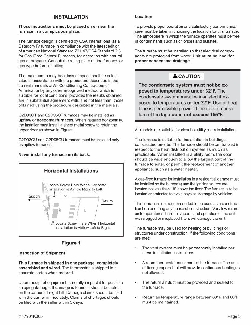
G2D93CT and G2D95CT furnaces may be installed asupflow or horizontal furnaces. When installed horizontally,the installer must install a sheet metal screw to retain theupper door as shown in Figure 1.
G2D93CU and G2D95CU furnaces must be installed onlyas upflow furnaces.
Never install any furnace on its back.
Inspection of Shipment
This furnace is shipped in one package, completelyassembled and wired. The thermostat is shipped in aseparate carton when ordered.
Upon receipt of equipment, carefully inspect it for possibleshipping damage. If damage is found, it should be notedon the carrier’s freight bill. Damage claims should be filedwith the carrier immediately. Claims of shortages shouldbe filed with the seller within 5 days.
Location
To provide proper operation and satisfactory performance,care must be taken in choosing the location for this furnace.The atmosphere in which the furnace operates must be freeof contaminants such as chlorides and sulfates.
The furnace must be installed so that electrical compo-nents are protected from water. Unit must be level forproper condensate drainage.
All models are suitable for closet or utility room installation.
The furnace is suitable for installation in buildingsconstructed on-site. The furnace should be centralized inrespect to the heat distribution system as much aspracticable. When installed in a utility room, the doorshould be wide enough to allow the largest part of thefurnace to enter, or permit the replacement of anotherappliance, such as a water heater.
A gas-fired furnace for installation in a residential garage mustbe installed so the burner(s) and the ignition source arelocated not less than 18" above the floor. The furnace is to belocated or protected to avoid physical damage by vehicles.
This furnace is not recommended to be used as a construc-tion heater during any phase of construction. Very low returnair temperatures, harmful vapors, and operation of the unitwith clogged or misplaced filters will damage the unit.
The furnace may be used for heating of buildings orstructures under construction, if the following conditionsare met:
• The vent system must be permanently installed perthese installation instructions.
• A room thermostat must control the furnace. The useof fixed jumpers that will provide continuous heating isnot allowed.
• The return air duct must be provided and sealed tothe furnace.
• Return air temperature range between 60°F and 80°Fmust be maintained.
The condensate system must not be ex-posed to temperatures under 32°F. Thecondensate system must be insulated if ex-posed to temperatures under 32°F. Use of heattape is permissible provided the rate tempera-ture of the tape does not exceed 155°F.
CAUTION
Horizontal Installations
Figure 1
# 47904K005Page 4
Unconfined Space
An unconfined space is defined as “a space whosevolume is more than 50 cubic feet per 1000 BTU per hourof the combined input rating of all appliances installed inthat space.” When a furnace is installed in an unconfinedspace in a building, it can be assumed that the infiltrationwill be sufficient to supply the required air. If the furnace isinstalled in a ventilated attic or crawl space, it is assumedthat the infiltration is sufficient to supply the required air.However, in a building of unusually tight construction,additional outdoor air should be provided.
• Air filters must be installed in the system and must bemaintained during construction.
• Air filters must be replaced upon construction comple-tion.
• The input rate and temperature rise must be set perthe furnace rating plate.
• One hundred percent (100%) outdoor air must beprovided for combustion air requirements duringconstruction. Temporary ducting may supply outdoorair to the furnace. Do not connect duct directly to thefurnace. Size the temporary duct following the instruc-tions given on page 5 in the Combustion andVentilation Air section regarding confined space withair from outside.
• The furnace heat exchanger, components, ductsystem, air filters, and evaporator coils must bethoroughly cleaned following final constructioncleanup.
• All furnace operating conditions (including ignition,input rate, temperature rise, and venting) must beverified according to these installation instructions.
G2D93CT and G2D95CT models installed in the horizon-tal position are approved for attic installations. If thefurnace is to be installed in an attic or other insulatedspace, it must be kept free and clear of insulatingmaterials.
To avoid property damage caused by condensate drainblockage, install a field-fabricated auxiliary drain pan witha separate drain line to the outside under the entirefurnace and drain system. Install according to local codes.
Clearances
All servicing and cleaning of the furnace can be performedfrom the front. If installed in a closet or utility room,provide 18" clearance in front for service if the door to theroom is not in line with the front of the furnace.
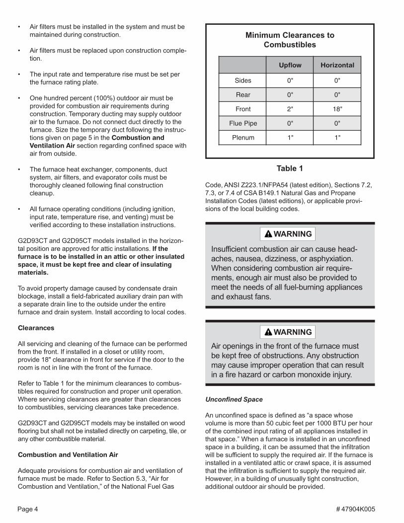
Refer to Table 1 for the minimum clearances to combus-tibles required for construction and proper unit operation.Where servicing clearances are greater than clearancesto combustibles, servicing clearances take precedence.
G2D93CT and G2D95CT models may be installed on woodflooring but shall not be installed directly on carpeting, tile, orany other combustible material.
Combustion and Ventilation Air
Adequate provisions for combustion air and ventilation offurnace must be made. Refer to Section 5.3, “Air forCombustion and Ventilation,” of the National Fuel Gas
Insufficient combustion air can cause head-aches, nausea, dizziness, or asphyxiation.When considering combustion air require-ments, enough air must also be provided tomeet the needs of all fuel-burning appliancesand exhaust fans.
WARNING
Air openings in the front of the furnace mustbe kept free of obstructions. Any obstructionmay cause improper operation that can resultin a fire hazard or carbon monoxide injury.
WARNING
Code, ANSI Z223.1/NFPA54 (latest edition), Sections 7.2,7.3, or 7.4 of CSA B149.1 Natural Gas and PropaneInstallation Codes (latest editions), or applicable provi-sions of the local building codes.
Table 1
Minimum Clearances toCombustibles
wolfpU latnoziroH
sediS "0 "0
raeR "0 "0
tnorF "2 "81
epiPeulF "0 "0
munelP "1 "1
# 47904K005 Page 5
5. Exposure to the following substances in the combustionair supply may also require outdoor air for combustion:
• Permanent wave solutions• Chlorinated waxes and cleaners• Chlorine-based swimming pool chemicals• Water softening chemicals• Deicing salts or chemicals• Carbon tetrachloride• Halogen-type refrigerants• Cleaning solvents (such as perchloroethylene)• Printing inks, paint removers, varnishes, etc.• Cements and glues• Antistatic fabric softeners for clothes dryers• Masonry acid washing materials• Chlorinated laundry products• Hydrochloric acid
Venting
The high efficiency of this furnace is accomplished by theremoval of both sensible and latent heat from the fluegases. The removal of latent heat results in the condensa-tion of moisture in the flue gases. This condensation occursin the secondary heat exchanger and in the vent system.Therefore, this furnace requires special venting consider-ations and the instructions must be followed to insure properoperation. All venting must be in accordance with the codeshaving jurisdiction in the area and these instructions.
G2D93CT, G2D93CU, G2D95CT, and G2D95CU modelscan be installed as either direct vent or non-direct ventunits. A direct vent (two pipe) installation requires that allthe air necessary for combustion be supplied from outsidethe dwelling through an air intake pipe. A non-direct vent(one pipe) installation uses air from inside the dwelling forcombustion.
The furnace is shipped with the air inlet pipe terminated tothe top panel for either inside or outside combustion air.An inlet air restrictor plate (see Figure 2 on page 6) issupplied with this furnace and can be found in the plasticbag containing these Installation Instructions and theUser’s Information Manual. This inlet restrictor plate mustbe used in all installations using inside air for combustion(non-direct vent).
To install the inlet restrictor plate:
1. Install the restrictor plate in the inlet pipe collar in thetop panel of the furnace.
2. Insert a 3" section of PVC pipe (field supplied) into thecollar. Use high temperature RTV sealant to attachPVC pipe to collar.
3. Attach a 90° elbow (field supplied) to the PVC pipe.Use high temperature RTV sealant to attach elbow toPVC pipe.
Confined Space
A confined space is defined as “a space whose volume isless than 50 cubic feet per 1000 BTU per hour of thecombined input rating of all appliances installed in thatspace.”
If the furnace is installed in a confined space within thebuilding and combustion air is taken from a heated space,the combustion air and ventilating air must enter and leavethe space through two permanent openings of equal area.One opening shall be located within 12" of the ceiling andthe other within 12" of the floor, each having a free area of1 square inch per 1000 BTU/HR of total input rating of allappliances within the space and not less than 100 squareinches each.
If the furnace is installed in a space within a building of tightconstruction, makeup air must be supplied from outdoors. Inthis case, one opening shall be within 12" of the ceiling andone opening within 12" of the floor. If combustion ducts arevertical, each opening shall have a free area of 1 squareinch per 4000 BTU/HR of the total input rating of all appli-ances within the enclosure. If horizontal combustion ductsare run, 1 square inch per 2000 BTU/HR is required.
Contaminated Combustion Air
Excessive exposure to contaminated combustion air willresult in safety and performance related problems. Therecommended source of combustion air is outdoor air.However, the use of indoor air in most applications isacceptable if the following guidelines are followed:
1. If the furnace is installed in a confined space, it isrecommended that the necessary combustion air comefrom the outdoors by way of an attic, crawl space, airduct, or direct opening.
2. If indoor combustion air is used, there must be noexposure to the substances listed in Item 5.
3. All provisions for indoor combustion air must meet therequirements for combustion air indicated in theNational Fuel Gas Code, ANSI Z223.1/NFPA 54(latest edition), and/or any applicable local codes. InCanada, see CSA B149.1, Natural Gas and PropaneInstallation Codes (latest edition).
4. The following types of installation may require outdoorair for combustion, due to chemical exposures:
• Commercial buildings• Buildings with indoor pools• Furnaces installed in laundry rooms• Furnaces installed in hobby or craft rooms• Furnaces installed near chemical storage areas
# 47904K005Page 6
All vents passing through floors, ceilings, and walls mustbe installed in accordance with National Fuel Gas Code,ANSI Z223.1/NFPA 54 (latest edition).
In all applications where the flue pipe is run throughan unconditioned space, 1/2" Armaflex or equivalentmust be used over the pipe. In extreme cold climates,3/4" Armaflex is recommended.
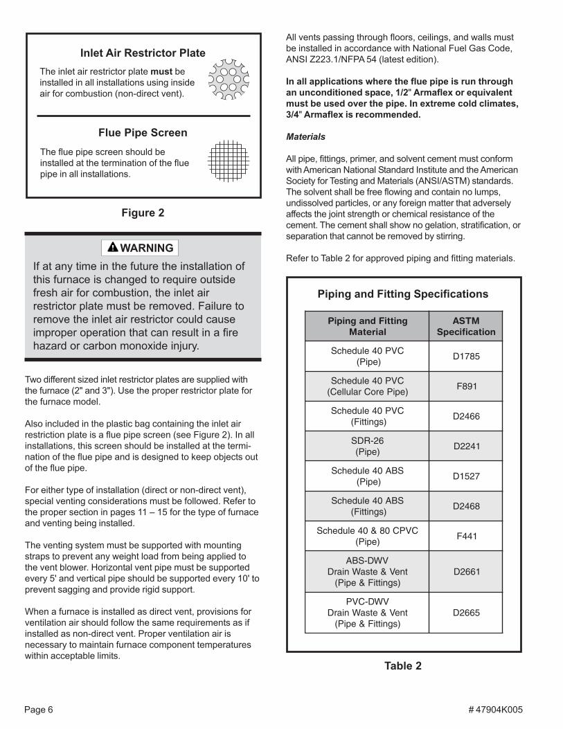
Materials
All pipe, fittings, primer, and solvent cement must conformwith American National Standard Institute and the AmericanSociety for Testing and Materials (ANSI/ASTM) standards.The solvent shall be free flowing and contain no lumps,undissolved particles, or any foreign matter that adverselyaffects the joint strength or chemical resistance of thecement. The cement shall show no gelation, stratification, orseparation that cannot be removed by stirring.
Refer to Table 2 for approved piping and fitting materials.
Two different sized inlet restrictor plates are supplied withthe furnace (2" and 3"). Use the proper restrictor plate forthe furnace model.
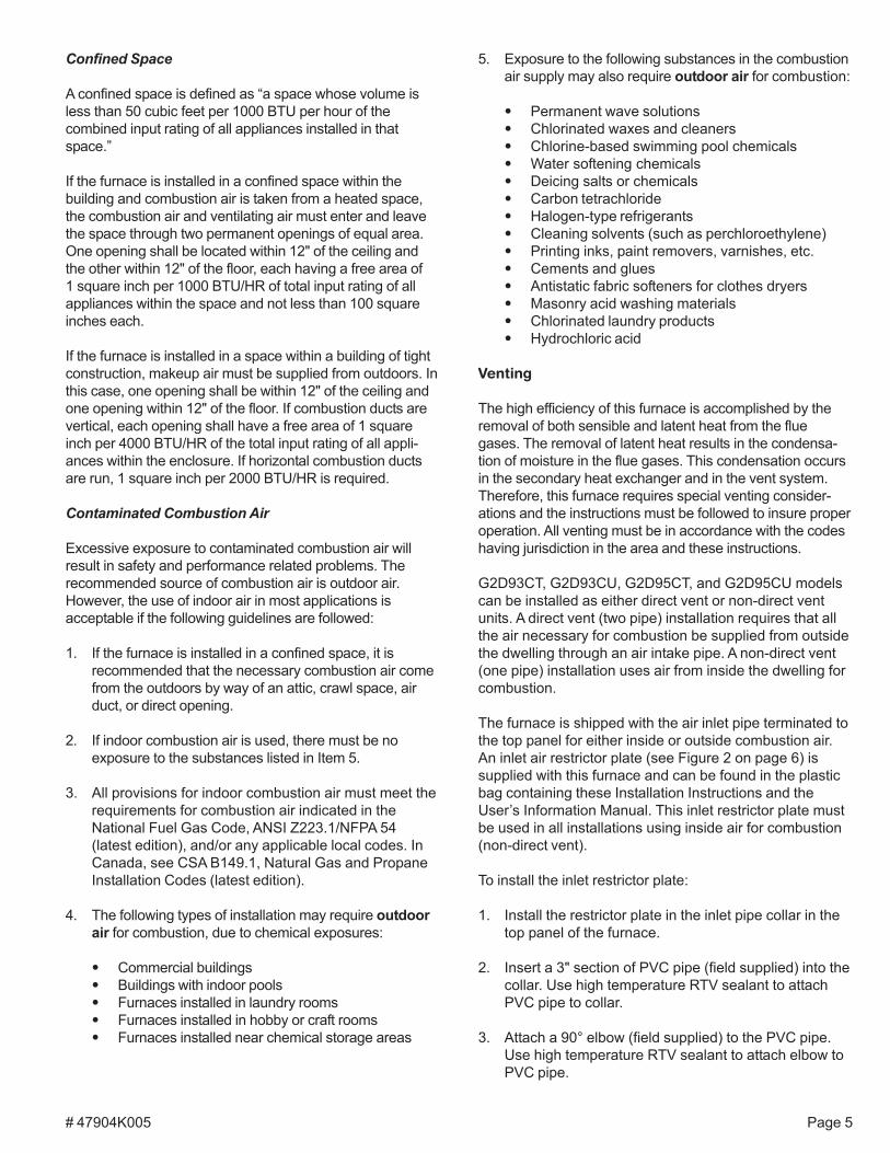
Also included in the plastic bag containing the inlet airrestriction plate is a flue pipe screen (see Figure 2). In allinstallations, this screen should be installed at the termi-nation of the flue pipe and is designed to keep objects outof the flue pipe.
For either type of installation (direct or non-direct vent),special venting considerations must be followed. Refer tothe proper section in pages 11 – 15 for the type of furnaceand venting being installed.
The venting system must be supported with mountingstraps to prevent any weight load from being applied tothe vent blower. Horizontal vent pipe must be supportedevery 5' and vertical pipe should be supported every 10' toprevent sagging and provide rigid support.
When a furnace is installed as direct vent, provisions forventilation air should follow the same requirements as ifinstalled as non-direct vent. Proper ventilation air isnecessary to maintain furnace component temperatureswithin acceptable limits.
Table 2
Piping and Fitting Specifications
gnittiFdnagnipiPlairetaM
MTSAnoitacificepS
CVP04eludehcS)epiP(
5871D
CVP04eludehcS)epiPeroCralulleC(
198F
CVP04eludehcS)sgnittiF(
6642D
62-RDS)epiP(
1422D
SBA04eludehcS)epiP(
7251D
SBA04eludehcS)sgnittiF(
8642D
CVPC08&04eludehcS)epiP(
144F
VWD-SBAtneV&etsaWniarD
)sgnittiF&epiP(1662D
VWD-CVPtneV&etsaWniarD
)sgnittiF&epiP(5662D
If at any time in the future the installation ofthis furnace is changed to require outsidefresh air for combustion, the inlet airrestrictor plate must be removed. Failure toremove the inlet air restrictor could causeimproper operation that can result in a firehazard or carbon monoxide injury.
WARNING
Flue Pipe ScreenThe flue pipe screen should beinstalled at the termination of the fluepipe in all installations.
Figure 2
Inlet Air Restrictor PlateThe inlet air restrictor plate must beinstalled in all installations using insideair for combustion (non-direct vent).
# 47904K005 Page 7
The primers and solvents used must also meet ASTMspecifications. PVC primer is specified in ASTM F656. UsePVC solvent as specified in ASTM D2564 and ABS solventcement as specified ASTM D2235. Low temperature solventcement is recommended. Metal or plastic strapping may beused for vent pipe hangers.
When making ABS joints, pieces can be prepared with acleaner. When joining ABS to PVC materials, use PVCsolvent cement as specified in ASTM D3138.
Preferred fittings are DWV style or long sweep. Seal alljoints gas tight with appropriate cement. In areas where ventand air intake pipes are exposed to abnormal stress or aresubject to damage, schedule 80 pipe should be used.
Category IV Furnace Limitations
This furnace shall not be connected to any Type B, BW,or L vent or vent connector and shall not be connected toany portion of a factory-built or masonry chimney. Thisfurnace is not to be common vented with any otherappliance. The vent pipe must not be connected to achimney flue serving a separate appliance designedto burn solid fuel.
Concentric Vent Kit
A concentric vent kit (model ACVK2) is available for usewhen installing this furnace as a direct vent furnace and theair intake and vent pipe are to be run through the same hole,whether horizontally through the wall or vertically through theroof (see Figure 3). Refer to the instructions included withthe concentric vent kit for installation specifics.
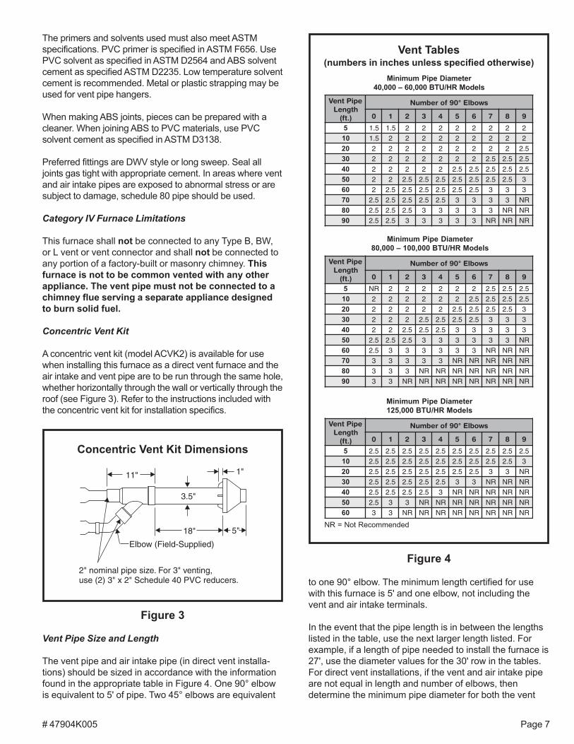
to one 90° elbow. The minimum length certified for usewith this furnace is 5' and one elbow, not including thevent and air intake terminals.
In the event that the pipe length is in between the lengthslisted in the table, use the next larger length listed. Forexample, if a length of pipe needed to install the furnace is27', use the diameter values for the 30' row in the tables.For direct vent installations, if the vent and air intake pipeare not equal in length and number of elbows, thendetermine the minimum pipe diameter for both the vent
Figure 4
Vent Tables(numbers in inches unless specified otherwise)
Minimum Pipe Diameter40,000 – 60,000 BTU/HR Models
NR = Not Recommended
Minimum Pipe Diameter125,000 BTU/HR Models
Minimum Pipe Diameter80,000 – 100,000 BTU/HR Models
epiPtneVhtgneL
).tf(
swoblE°09forebmuN
0 1 2 3 4 5 6 7 8 9
5 5.1 5.1 2 2 2 2 2 2 2 201 5.1 2 2 2 2 2 2 2 2 202 2 2 2 2 2 2 2 2 2 5.203 2 2 2 2 2 2 2 5.2 5.2 5.204 2 2 2 2 2 5.2 5.2 5.2 5.2 5.205 2 2 5.2 5.2 5.2 5.2 5.2 5.2 5.2 306 2 5.2 5.2 5.2 5.2 5.2 5.2 3 3 307 5.2 5.2 5.2 5.2 5.2 3 3 3 3 RN08 5.2 5.2 5.2 3 3 3 3 3 RN RN09 5.2 5.2 3 3 3 3 3 RN RN RN
epiPtneVhtgneL
).tf(
swoblE°09forebmuN
0 1 2 3 4 5 6 7 8 9
5 RN 2 2 2 2 2 2 5.2 5.2 5.201 2 2 2 2 2 2 5.2 5.2 5.2 5.202 2 2 2 2 2 5.2 5.2 5.2 5.2 303 2 2 2 5.2 5.2 5.2 5.2 3 3 304 2 2 5.2 5.2 5.2 3 3 3 3 305 5.2 5.2 5.2 3 3 3 3 3 3 RN06 5.2 3 3 3 3 3 3 RN RN RN07 3 3 3 3 3 RN RN RN RN RN08 3 3 3 RN RN RN RN RN RN RN09 3 3 RN RN RN RN RN RN RN RN
epiPtneVhtgneL
).tf(
swoblE°09forebmuN
0 1 2 3 4 5 6 7 8 9
5 5.2 5.2 5.2 5.2 5.2 5.2 5.2 5.2 5.2 5.201 5.2 5.2 5.2 5.2 5.2 5.2 5.2 5.2 5.2 302 5.2 5.2 5.2 5.2 5.2 5.2 5.2 3 3 RN03 5.2 5.2 5.2 5.2 5.2 3 3 RN RN RN04 5.2 5.2 5.2 5.2 3 RN RN RN RN RN05 5.2 3 3 RN RN RN RN RN RN RN06 3 3 RN RN RN RN RN RN RN RN
Figure 3
Concentric Vent Kit Dimensions
Vent Pipe Size and Length
The vent pipe and air intake pipe (in direct vent installa-tions) should be sized in accordance with the informationfound in the appropriate table in Figure 4. One 90° elbowis equivalent to 5' of pipe. Two 45° elbows are equivalent
# 47904K005Page 8
and air intake. If the results indicate different diameters,use the larger of the two for both the vent and air intake.Under no circumstances should the vent and airintake pipe size be different in diameter. For installationdetails, refer to the appropriate section in pages 11 – 15for the unit model and type of installation.
Horizontal Venting
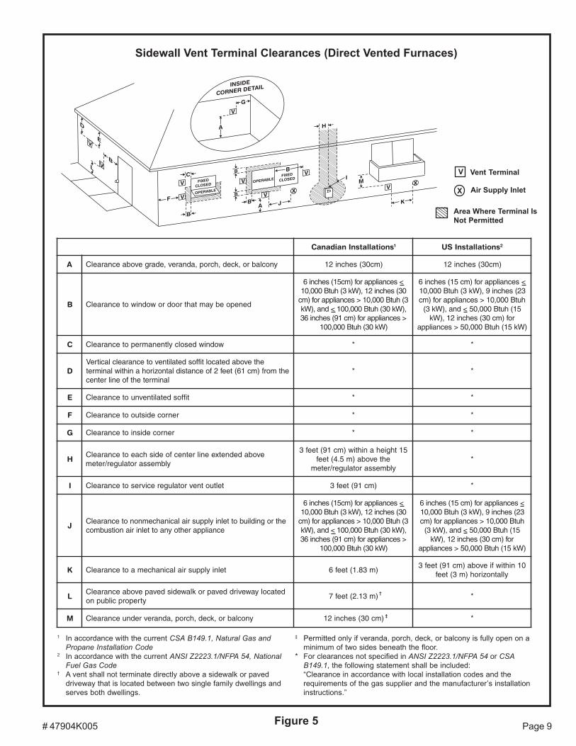
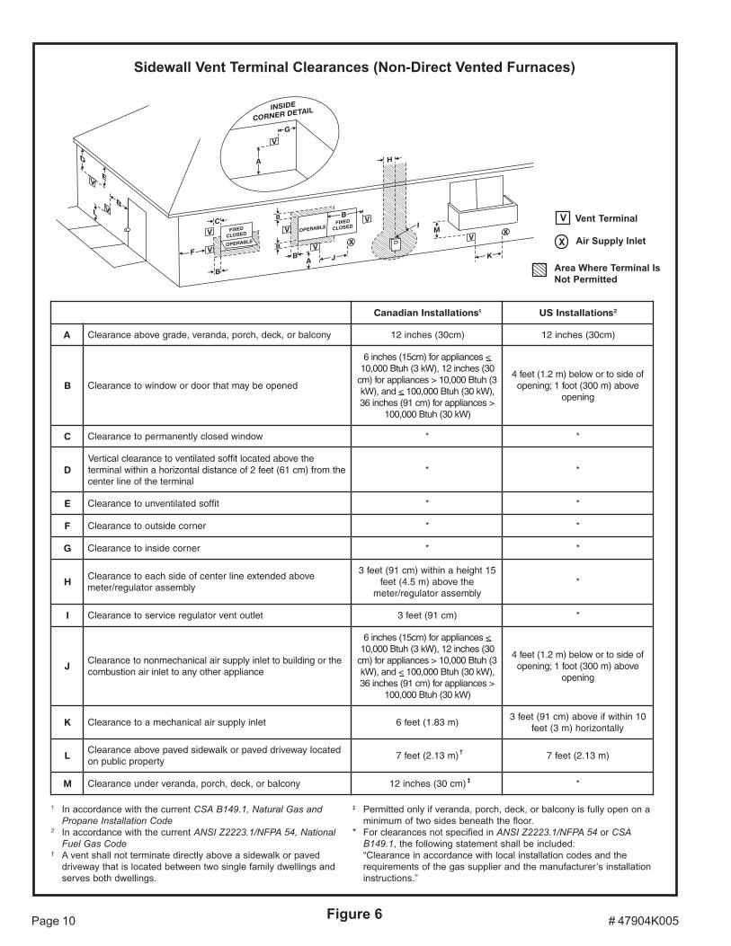
The vent for this appliance shall not terminate over publicwalkways; or near soffit vents or crawl space vents orother areas where condensate or vapor could create anuisance or hazard or cause property damage; or wherecondensate vapor could cause damage or could bedetrimental to the operation of regulators, relief valves, orother equipment. See Figures 5 and 6 on pages 9 and 10for additional information on where the horizontal ventterminal can and cannot terminate.
For horizontal venting in situations where clearance tofloor joists is limited, see Horizontal Venting – LowClearance Installations on page 15.
# 47904K005 Page 9Figure 5
Sidewall Vent Terminal Clearances (Direct Vented Furnaces)
1 In accordance with the current CSA B149.1, Natural Gas andPropane Installation Code
2 In accordance with the current ANSI Z2223.1/NFPA 54, NationalFuel Gas Code
† A vent shall not terminate directly above a sidewalk or paveddriveway that is located between two single family dwellings andserves both dwellings.
‡ Permitted only if veranda, porch, deck, or balcony is fully open on aminimum of two sides beneath the floor.
* For clearances not specified in ANSI Z2223.1/NFPA 54 or CSAB149.1, the following statement shall be included:“Clearance in accordance with local installation codes and therequirements of the gas supplier and the manufacturer’s installationinstructions.”
†
‡
V
X
Vent Terminal
Air Supply Inlet
Area Where Terminal IsNot Permitted
snoitallatsnInaidanaC 1 snoitallatsnISU 2
A ynoclabro,kced,hcrop,adnarev,edargevobaecnaraelC )mc03(sehcni21 )mc03(sehcni21
B denepoebyamtahtroodrowodniwotecnaraelC
<secnailpparof)mc51(sehcni603(sehcni21,)Wk3(hutB000,013(hutB000,01>secnailpparof)mc,)Wk03(hutB000,001<dna,)Wk
>secnailpparof)mc19(sehcni63)Wk03(hutB000,001
<secnailpparof)mc51(sehcni632(sehcni9,)Wk3(hutB000,01hutB000,01>secnailpparof)mc
51(hutB000,05<dna,)Wk3(rof)mc03(sehcni21,)Wk
)Wk51(hutB000,05>secnailppa
C wodniwdesolcyltnenamrepotecnaraelC * *
DehtevobadetacoltiffosdetalitnevotecnaraelclacitreV
ehtmorf)mc16(teef2foecnatsidlatnozirohanihtiwlanimretlanimretehtfoenilretnec
* *
E tiffosdetalitnevnuotecnaraelC * *
F renrocedistuootecnaraelC * *
G renrocedisniotecnaraelC * *
HevobadednetxeenilretnecfoedishcaeotecnaraelC
ylbmessarotaluger/retem
51thgiehanihtiw)mc19(teef3ehtevoba)m5.4(teef
ylbmessarotaluger/retem*
I teltuotnevrotalugerecivresotecnaraelC )mc19(teef3 *
JehtrognidliubottelniylppusrialacinahcemnonotecnaraelC
ecnailpparehtoynaottelnirianoitsubmoc
<secnailpparof)mc51(sehcni603(sehcni21,)Wk3(hutB000,013(hutB000,01>secnailpparof)mc,)Wk03(hutB000,001<dna,)Wk
>secnailpparof)mc19(sehcni63)Wk03(hutB000,001
<secnailpparof)mc51(sehcni632(sehcni9,)Wk3(hutB000,01hutB000,01>secnailpparof)mc
51(hutB000,05<dna,)Wk3(rof)mc03(sehcni21,)Wk
)Wk51(hutB000,05>secnailppa
K telniylppusrialacinahcemaotecnaraelC )m38.1(teef601nihtiwfievoba)mc19(teef3
yllatnoziroh)m3(teef
LdetacolyawevirddevaproklawedisdevapevobaecnaraelC
ytreporpcilbupno)m31.2(teef7 *
M ynoclabro,kced,hcrop,adnarevrednuecnaraelC )mc03(sehcni21 *
# 47904K005Page 10 Figure 6
Sidewall Vent Terminal Clearances (Non-Direct Vented Furnaces)
1 In accordance with the current CSA B149.1, Natural Gas andPropane Installation Code
2 In accordance with the current ANSI Z2223.1/NFPA 54, NationalFuel Gas Code
† A vent shall not terminate directly above a sidewalk or paveddriveway that is located between two single family dwellings andserves both dwellings.
‡ Permitted only if veranda, porch, deck, or balcony is fully open on aminimum of two sides beneath the floor.
* For clearances not specified in ANSI Z2223.1/NFPA 54 or CSAB149.1, the following statement shall be included:“Clearance in accordance with local installation codes and therequirements of the gas supplier and the manufacturer’s installationinstructions.”
†
‡
V
X
Vent Terminal
Air Supply Inlet
Area Where Terminal IsNot Permitted
snoitallatsnInaidanaC 1 snoitallatsnISU 2
A ynoclabro,kced,hcrop,adnarev,edargevobaecnaraelC )mc03(sehcni21 )mc03(sehcni21
B denepoebyamtahtroodrowodniwotecnaraelC
<secnailpparof)mc51(sehcni603(sehcni21,)Wk3(hutB000,013(hutB000,01>secnailpparof)mc,)Wk03(hutB000,001<dna,)Wk
>secnailpparof)mc19(sehcni63)Wk03(hutB000,001
foedisotrowoleb)m2.1(teef4evoba)m003(toof1;gninepo
gninepo
C wodniwdesolcyltnenamrepotecnaraelC * *
DehtevobadetacoltiffosdetalitnevotecnaraelclacitreV
ehtmorf)mc16(teef2foecnatsidlatnozirohanihtiwlanimretlanimretehtfoenilretnec
* *
E tiffosdetalitnevnuotecnaraelC * *
F renrocedistuootecnaraelC * *
G renrocedisniotecnaraelC * *
HevobadednetxeenilretnecfoedishcaeotecnaraelC
ylbmessarotaluger/retem
51thgiehanihtiw)mc19(teef3ehtevoba)m5.4(teef
ylbmessarotaluger/retem*
I teltuotnevrotalugerecivresotecnaraelC )mc19(teef3 *
JehtrognidliubottelniylppusrialacinahcemnonotecnaraelC
ecnailpparehtoynaottelnirianoitsubmoc
<secnailpparof)mc51(sehcni603(sehcni21,)Wk3(hutB000,013(hutB000,01>secnailpparof)mc,)Wk03(hutB000,001<dna,)Wk
>secnailpparof)mc19(sehcni63)Wk03(hutB000,001
foedisotrowoleb)m2.1(teef4evoba)m003(toof1;gninepo
gninepo
K telniylppusrialacinahcemaotecnaraelC )m38.1(teef601nihtiwfievoba)mc19(teef3
yllatnoziroh)m3(teef
LdetacolyawevirddevaproklawedisdevapevobaecnaraelC
ytreporpcilbupno)m31.2(teef7 )m31.2(teef7
M ynoclabro,kced,hcrop,adnarevrednuecnaraelC )mc03(sehcni21 *
# 47904K005 Page 11
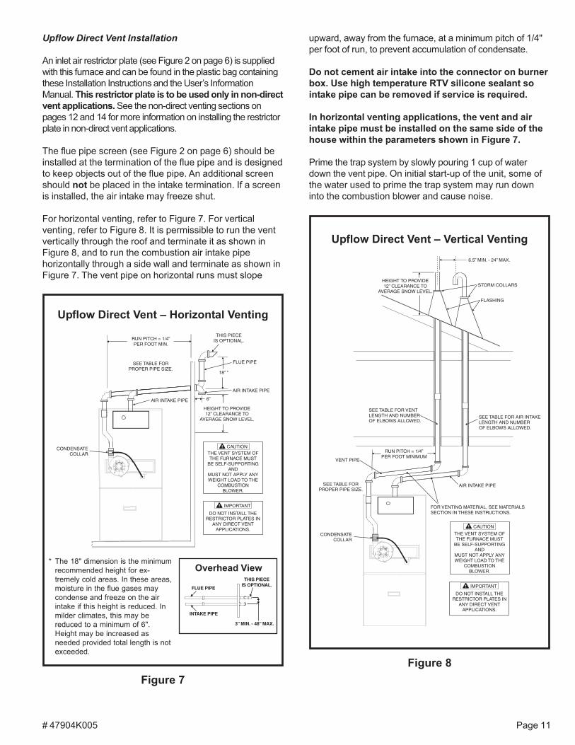
Upflow Direct Vent Installation
An inlet air restrictor plate (see Figure 2 on page 6) is suppliedwith this furnace and can be found in the plastic bag containingthese Installation Instructions and the User’s InformationManual. This restrictor plate is to be used only in non-directvent applications. See the non-direct venting sections onpages 12 and 14 for more information on installing the restrictorplate in non-direct vent applications.
The flue pipe screen (see Figure 2 on page 6) should beinstalled at the termination of the flue pipe and is designedto keep objects out of the flue pipe. An additional screenshould not be placed in the intake termination. If a screenis installed, the air intake may freeze shut.
For horizontal venting, refer to Figure 7. For verticalventing, refer to Figure 8. It is permissible to run the ventvertically through the roof and terminate it as shown inFigure 8, and to run the combustion air intake pipehorizontally through a side wall and terminate as shown inFigure 7. The vent pipe on horizontal runs must slope
upward, away from the furnace, at a minimum pitch of 1/4"per foot of run, to prevent accumulation of condensate.
Do not cement air intake into the connector on burnerbox. Use high temperature RTV silicone sealant sointake pipe can be removed if service is required.
In horizontal venting applications, the vent and airintake pipe must be installed on the same side of thehouse within the parameters shown in Figure 7.
Prime the trap system by slowly pouring 1 cup of waterdown the vent pipe. On initial start-up of the unit, some ofthe water used to prime the trap system may run downinto the combustion blower and cause noise.
Figure 7
Upflow Direct Vent – Horizontal Venting
* The 18" dimension is the minimumrecommended height for ex-tremely cold areas. In these areas,moisture in the flue gases maycondense and freeze on the airintake if this height is reduced. Inmilder climates, this may bereduced to a minimum of 6".Height may be increased asneeded provided total length is notexceeded.
THIS PIECEIS OPTIONAL.
INTAKE PIPE
FLUE PIPE
3” MIN. - 48” MAX.
Overhead View
Upflow Direct Vent – Vertical Venting
Figure 8
# 47904K005Page 12
Horizontal Direct Vent Installation
An inlet air restrictor plate (see Figure 2 on page 6) is suppliedwith this furnace and can be found in the plastic bag containingthese Installation Instructions and the User’s InformationManual. This restrictor plate is to be used only in non-directvent applications. See the non-direct venting sections on thispage and page 13 for more information on installing therestrictor plate in non-direct vent applications.
The flue pipe screen (see Figure 2 on page 6) should beinstalled at the termination of the flue pipe and is designedto keep objects out of the flue pipe. An additional screenshould not be placed in the intake termination. If a screen isinstalled, the air intake may freeze shut.
The 18" dimension shown in Figure 11 on page 12 is theminimum recommended height for extremely cold areas. In
Figure 9
Upflow Non-Direct VentHorizontal Venting
Upflow Non-Direct VentVertical Venting
Figure 10
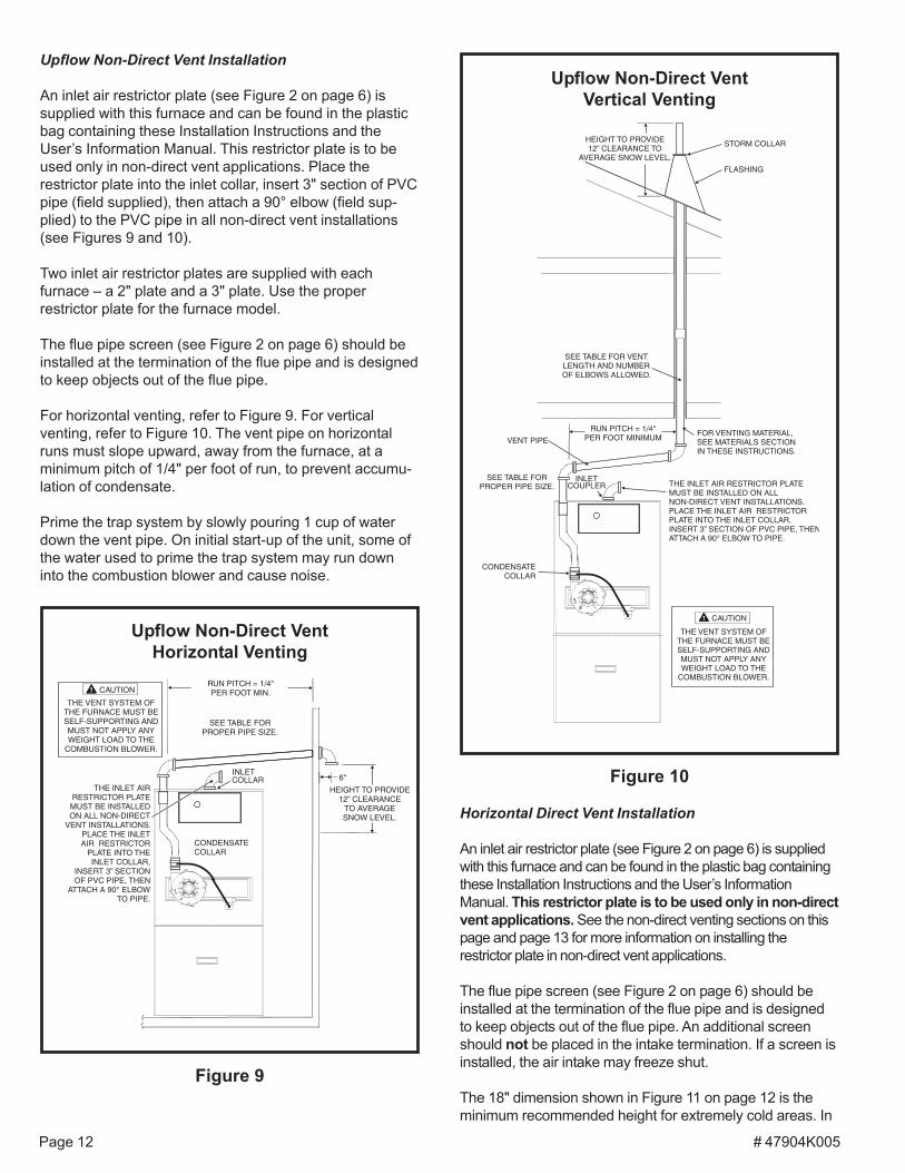
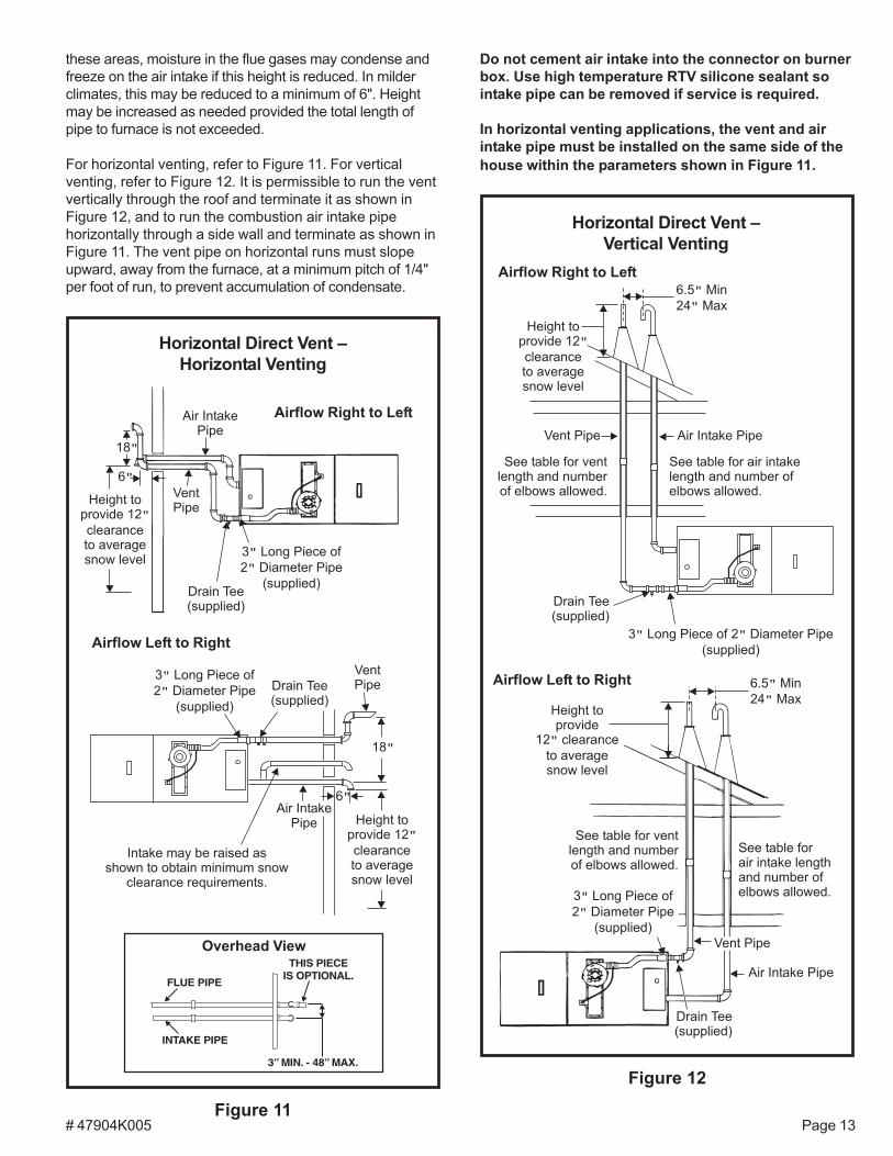
Upflow Non-Direct Vent Installation
An inlet air restrictor plate (see Figure 2 on page 6) issupplied with this furnace and can be found in the plasticbag containing these Installation Instructions and theUser’s Information Manual. This restrictor plate is to beused only in non-direct vent applications. Place therestrictor plate into the inlet collar, insert 3" section of PVCpipe (field supplied), then attach a 90° elbow (field sup-plied) to the PVC pipe in all non-direct vent installations(see Figures 9 and 10).
Two inlet air restrictor plates are supplied with eachfurnace – a 2" plate and a 3" plate. Use the properrestrictor plate for the furnace model.
The flue pipe screen (see Figure 2 on page 6) should beinstalled at the termination of the flue pipe and is designedto keep objects out of the flue pipe.
For horizontal venting, refer to Figure 9. For verticalventing, refer to Figure 10. The vent pipe on horizontalruns must slope upward, away from the furnace, at aminimum pitch of 1/4" per foot of run, to prevent accumu-lation of condensate.
Prime the trap system by slowly pouring 1 cup of waterdown the vent pipe. On initial start-up of the unit, some ofthe water used to prime the trap system may run downinto the combustion blower and cause noise.
# 47904K005 Page 13
these areas, moisture in the flue gases may condense andfreeze on the air intake if this height is reduced. In milderclimates, this may be reduced to a minimum of 6". Heightmay be increased as needed provided the total length ofpipe to furnace is not exceeded.
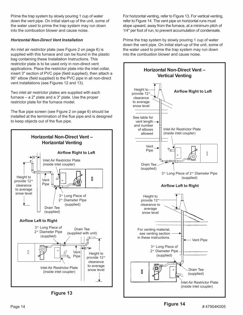
For horizontal venting, refer to Figure 11. For verticalventing, refer to Figure 12. It is permissible to run the ventvertically through the roof and terminate it as shown inFigure 12, and to run the combustion air intake pipehorizontally through a side wall and terminate as shown inFigure 11. The vent pipe on horizontal runs must slopeupward, away from the furnace, at a minimum pitch of 1/4"per foot of run, to prevent accumulation of condensate.
Do not cement air intake into the connector on burnerbox. Use high temperature RTV silicone sealant sointake pipe can be removed if service is required.
In horizontal venting applications, the vent and airintake pipe must be installed on the same side of thehouse within the parameters shown in Figure 11.
Horizontal Direct Vent –Horizontal Venting
Figure 11
3 Long Piece of
2 Diameter Pipe
(supplied)
�
�
18�
6�
Drain Tee(supplied)
Height toprovide 12
clearanceto averagesnow level
�
VentPipe
Air IntakePipe
Intake may be raised asshown to obtain minimum snow
clearance requirements.
Airflow Left to Right
Airflow Right to Left
THIS PIECEIS OPTIONAL.
INTAKE PIPE
FLUE PIPE
3” MIN. - 48” MAX.
Overhead View
Figure 12
Horizontal Direct Vent –Vertical Venting
Height toprovide 12
clearanceto averagesnow level
�
Drain Tee(supplied)
3 Long Piece of 2 Diameter Pipe
(supplied)
� �
6.5 Min
24 Max
�
�
Vent Pipe Air Intake Pipe
See table for air intakelength and number ofelbows allowed.
See table for ventlength and numberof elbows allowed.
Airflow Right to Left
Airflow Left to Right
# 47904K005Page 14
Prime the trap system by slowly pouring 1 cup of waterdown the vent pipe. On initial start-up of the unit, some ofthe water used to prime the trap system may run downinto the combustion blower and cause noise.
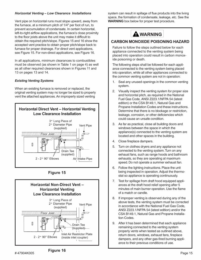
Horizontal Non-Direct Vent Installation
An inlet air restrictor plate (see Figure 2 on page 6) issupplied with this furnace and can be found in the plasticbag containing these Installation Instructions. Thisrestrictor plate is to be used only in non-direct ventapplications. Place the restrictor plate into the inlet collar,insert 3" section of PVC pipe (field supplied), then attach a90° elbow (field supplied) to the PVC pipe in all non-directvent installations (see Figures 12 and 13).
Two inlet air restrictor plates are supplied with eachfurnace – a 2" plate and a 3" plate. Use the properrestrictor plate for the furnace model.
The flue pipe screen (see Figure 2 on page 6) should beinstalled at the termination of the flue pipe and is designedto keep objects out of the flue pipe.
For horizontal venting, refer to Figure 13. For vertical venting,refer to Figure 14. The vent pipe on horizontal runs mustslope upward, away from the furnace, at a minimum pitch of1/4" per foot of run, to prevent accumulation of condensate.
Prime the trap system by slowly pouring 1 cup of waterdown the vent pipe. On initial start-up of the unit, some ofthe water used to prime the trap system may run downinto the combustion blower and cause noise.
Airflow Right to Left
Figure 14
Horizontal Non-Direct Vent –Vertical Venting
Airflow Left to Right
Inlet Air Restrictor Plate(inside inlet coupler)
VentPipe
Height toprovide 12
clearanceto averagesnow level
�
Drain Tee(supplied)
3 Long Piece of 2 Diameter Pipe
(supplied)
� �
See table forvent length
and numberof elbows
allowed
Airflow Left to Right
Airflow Right to Left
3 Long Piece of
2 Diameter Pipe
(supplied)
�
�
6�
Drain Tee(supplied with unit)
Inlet Air Restrictor Plate(inside inlet coupler)
VentPipe
Height toprovide 12
clearanceto averagesnow level
�
Figure 13
Horizontal Non-Direct Vent –Horizontal Venting
# 47904K005 Page 15
Horizontal Venting – Low Clearance Installations
Vent pipe on horizontal runs must slope upward, away fromthe furnace, at a minimum pitch of 1/4" per foot of run, toprevent accumulation of condensate. In certain horizontal,left-to-right airflow applications, the furnace’s close proximityto the floor joists above the unit may make it difficult toobtain the required pitch/slope. Figures 15 and 16 show theaccepted vent practice to obtain proper pitch/slope back tofurnace for proper drainage. For direct vent applications,see Figure 15. For non-direct applications, see Figure 16.
In all applications, minimum clearances to combustiblesmust be observed (as shown in Table 1 on page 4) as wellas all other required clearances shown in Figures 11 and13 on pages 13 and 14.
Existing Venting Systems
When an existing furnace is removed or replaced, theoriginal venting system may no longer be sized to properlyvent the attached appliances. An improperly sized venting
Figure 15
Horizontal Direct Vent – Horizontal VentingLow Clearance Installation
system can result in spillage of flue products into the livingspace, the formation of condensate, leakage, etc. See theWARNING box below for proper test procedure.
Failure to follow the steps outlined below for eachappliance connected to the venting system beingplaced into operation could result in carbon monox-ide poisoning or death.
The following steps shall be followed for each appli-ance connected to the venting system being placedinto operation, while all other appliances connected tothe common venting system are not in operation:
1. Seal any unused openings in the common ventingsystem.
2. Visually inspect the venting system for proper sizeand horizontal pitch, as required in the NationalFuel Gas Code, ANSI Z223.1/NFPA 54 (latestedition) or the CSA B149.1, Natural Gas andPropane Installation Codes and these instructions.Determine that there is no blockage or restriction,leakage, corrosion, or other deficiencies whichcould cause an unsafe condition.
3. As far as practical, close all building doors andwindows between the space in which theappliance(s) connected to the venting system arelocated and other spaces in the building.
4. Close fireplace dampers.
5. Turn on clothes dryers and any appliance notconnected to the venting system. Turn on anyexhaust fans, such as range hoods and bathroomexhausts, so they are operating at maximumspeed. Do not operate a summer exhaust fan.
6. Follow the lighting instructions. Place the unitbeing inspected in operation. Adjust the thermo-stat so appliance is operating continuously.
7. Test for spillage from draft hood equipped appli-ances at the draft hood relief opening after 5minutes of main burner operation. Use the flameof a match or candle.
8. If improper venting is observed during any of theabove tests, the venting system must be correctedin accordance with the National Fuel Gas Code,ANSI Z223.1/NFPA 54 (latest edition) and/or theCSA B149.1, Natural Gas and Propane Installa-tion Codes.
9. After it has been determined that each applianceremaining connected to the venting systemproperly vents when tested as outlined above,return doors, windows, exhaust fans, fireplacedampers, and any other gas-fired burning appli-ance to their previous conditions of use.
CARBON MONOXIDE POISONING HAZARD
WARNING
Figure 16
Horizontal Non-Direct Vent –Horizontal Venting
Low Clearance Installation
# 47904K005Page 16
Figure 17
Condensate Disposal – Upflow
TH
RU
.
59
.69
/56
.64
1/2” NPT PLUG(SUPPLIED)
1/2” NPT x 3/4” PVC ADAPTER(SUPPLIED)
3/4” PVC
TEE MUST REMAINOPEN
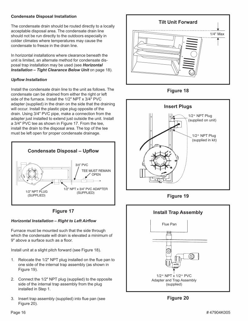
Condensate Disposal Installation
The condensate drain should be routed directly to a locallyacceptable disposal area. The condensate drain lineshould not be run directly to the outdoors especially incolder climates where temperatures may cause thecondensate to freeze in the drain line.
In horizontal installations where clearance beneath theunit is limited, an alternate method for condensate dis-posal trap installation may be used (see HorizontalInstallation – Tight Clearance Below Unit on page 18).
Upflow Installation
Install the condensate drain line to the unit as follows. Thecondensate can be drained from either the right or leftside of the furnace. Install the 1/2" NPT x 3/4" PVCadapter (supplied) in the drain on the side that the drainingwill occur. Install the plastic pipe plug opposite of thedrain. Using 3/4" PVC pipe, make a connection from theadapter just installed to extend just outside the unit. Installa 3/4" PVC tee as shown in Figure 17. From the tee,install the drain to the disposal area. The top of the teemust be left open for proper condensate drainage.
Horizontal Installation – Right to Left Airflow
Furnace must be mounted such that the side throughwhich the condensate will drain is elevated a minimum of9" above a surface such as a floor.
Install unit at a slight pitch forward (see Figure 18).
1. Relocate the 1/2" NPT plug installed on the flue pan toone side of the internal trap assembly (as shown inFigure 19).
2. Connect the 1/2" NPT plug (supplied) to the oppositeside of the internal trap assembly from the pluginstalled in Step 1.
3. Insert trap assembly (supplied) into flue pan (seeFigure 20).
Figure 18
Figure 20
Install Trap Assembly
1/2 NPT x 1/2 PVC
Adapter and Trap Assembly(supplied)
� �
Flue Pan
Figure 19
Insert Plugs
1/2 NPT Plug
(supplied in kit)
�
1/2 NPT Plug
(supplied on unit)
�
Tilt Unit Forward
1/4" Max
# 47904K005 Page 17
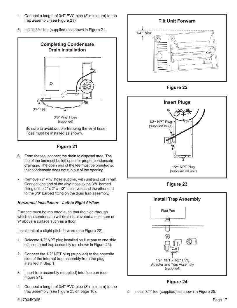
6. From the tee, connect the drain to disposal area. Thetop of the tee must be left open for proper condensatedrainage. The open end of the tee must be oriented sothat condensate does not run out of the opening.
7. Remove 72" vinyl hose supplied with unit and cut in half.Connect one end of the vinyl hose to the 3/8" barbedfitting of the 2" x 2" x 1/2" tee in vent and the other endto the 3/8" barbed fitting on the drain trap assembly.
Horizontal Installation – Left to Right Airflow
Furnace must be mounted such that the side throughwhich the condensate will drain is elevated a minimum of9" above a surface such as a floor.
Install unit at a slight pitch forward (see Figure 22).
1. Relocate 1/2" NPT plug installed on flue pan to one sideof the internal trap assembly (as shown in Figure 23).
2. Connect the 1/2" NPT plug (supplied) to the oppositeside of the internal trap assembly from the pluginstalled in Step 1.
3. Insert trap assembly (supplied) into flue pan (seeFigure 24).
4. Connect a length of 3/4" PVC pipe (3' minimum) to thetrap assembly (see Figure 25 on page 18).
4. Connect a length of 3/4" PVC pipe (3' minimum) to thetrap assembly (see Figure 21).
5. Install 3/4" tee (supplied) as shown in Figure 21.
5. Install 3/4" tee (supplied) as shown in Figure 25.
Figure 24
Install Trap Assembly
1/2 NPT x 1/2 PVC
Adapter and Trap Assembly(supplied)
� �
Flue Pan
Figure 23
1/2 NPT Plug
(supplied in kit)
�
1/2 NPT Plug
(supplied on unit)
�
Insert Plugs
Completing CondensateDrain Installation
3/4" Tee
3/8" Vinyl Hose(supplied)
Be sure to avoid double-trapping the vinyl hose.Hose must be installed as shown.
Figure 21
Figure 22
Tilt Unit Forward
1/4 Max.�
# 47904K005Page 18
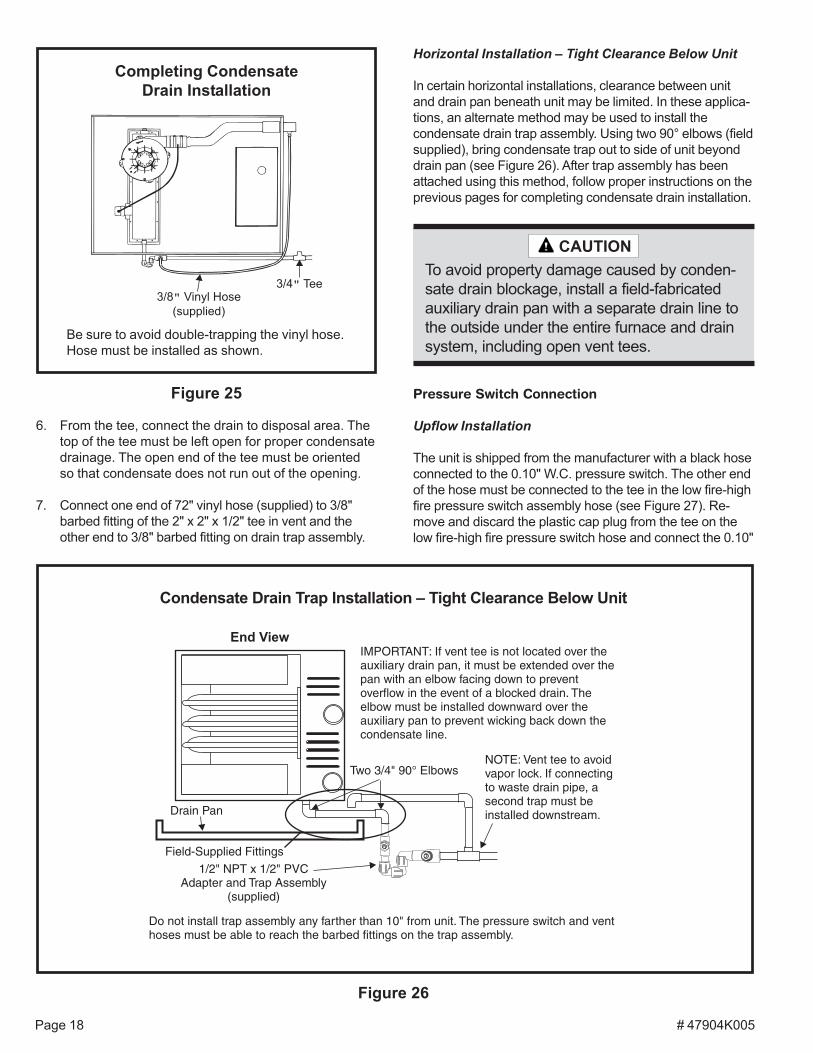
6. From the tee, connect the drain to disposal area. Thetop of the tee must be left open for proper condensatedrainage. The open end of the tee must be orientedso that condensate does not run out of the opening.
7. Connect one end of 72" vinyl hose (supplied) to 3/8"barbed fitting of the 2" x 2" x 1/2" tee in vent and theother end to 3/8" barbed fitting on drain trap assembly.
Figure 25
Completing CondensateDrain Installation
3/4 Tee�
3/8 Vinyl Hose
(supplied)
�
Be sure to avoid double-trapping the vinyl hose.Hose must be installed as shown.
Figure 26
Condensate Drain Trap Installation – Tight Clearance Below Unit
Drain Pan
Two 3/4" 90° Elbows
1/2" NPT x 1/2" PVCAdapter and Trap Assembly
(supplied)
End View
Field-Supplied Fittings
IMPORTANT: If vent tee is not located over theauxiliary drain pan, it must be extended over thepan with an elbow facing down to preventoverflow in the event of a blocked drain. Theelbow must be installed downward over theauxiliary pan to prevent wicking back down thecondensate line.
Do not install trap assembly any farther than 10" from unit. The pressure switch and venthoses must be able to reach the barbed fittings on the trap assembly.
NOTE: Vent tee to avoidvapor lock. If connectingto waste drain pipe, asecond trap must beinstalled downstream.
Horizontal Installation – Tight Clearance Below Unit
In certain horizontal installations, clearance between unitand drain pan beneath unit may be limited. In these applica-tions, an alternate method may be used to install thecondensate drain trap assembly. Using two 90° elbows (fieldsupplied), bring condensate trap out to side of unit beyonddrain pan (see Figure 26). After trap assembly has beenattached using this method, follow proper instructions on theprevious pages for completing condensate drain installation.
Pressure Switch Connection
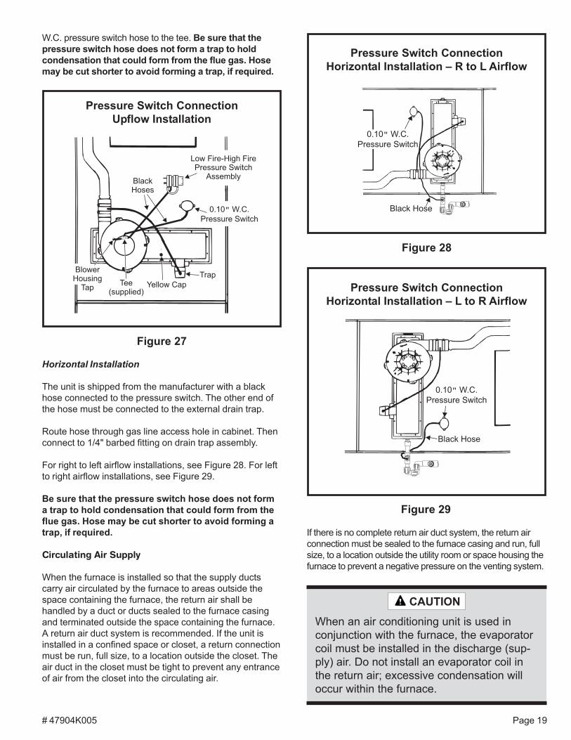
Upflow Installation
The unit is shipped from the manufacturer with a black hoseconnected to the 0.10" W.C. pressure switch. The other endof the hose must be connected to the tee in the low fire-highfire pressure switch assembly hose (see Figure 27). Re-move and discard the plastic cap plug from the tee on thelow fire-high fire pressure switch hose and connect the 0.10"
To avoid property damage caused by conden-sate drain blockage, install a field-fabricatedauxiliary drain pan with a separate drain line tothe outside under the entire furnace and drainsystem, including open vent tees.
CAUTION
# 47904K005 Page 19
W.C. pressure switch hose to the tee. Be sure that thepressure switch hose does not form a trap to holdcondensation that could form from the flue gas. Hosemay be cut shorter to avoid forming a trap, if required.
Horizontal Installation
The unit is shipped from the manufacturer with a blackhose connected to the pressure switch. The other end ofthe hose must be connected to the external drain trap.
Route hose through gas line access hole in cabinet. Thenconnect to 1/4" barbed fitting on drain trap assembly.
For right to left airflow installations, see Figure 28. For leftto right airflow installations, see Figure 29.
Be sure that the pressure switch hose does not forma trap to hold condensation that could form from theflue gas. Hose may be cut shorter to avoid forming atrap, if required.
Circulating Air Supply
When the furnace is installed so that the supply ductscarry air circulated by the furnace to areas outside thespace containing the furnace, the return air shall behandled by a duct or ducts sealed to the furnace casingand terminated outside the space containing the furnace.A return air duct system is recommended. If the unit isinstalled in a confined space or closet, a return connectionmust be run, full size, to a location outside the closet. Theair duct in the closet must be tight to prevent any entranceof air from the closet into the circulating air.
Pressure Switch ConnectionUpflow Installation
Figure 27
BlackHoses
Tee(supplied)
0.10 W.C.
Pressure Switch
�
Low Fire-High FirePressure Switch
Assembly
Yellow Cap
BlowerHousing
Tap
Trap
If there is no complete return air duct system, the return airconnection must be sealed to the furnace casing and run, fullsize, to a location outside the utility room or space housing thefurnace to prevent a negative pressure on the venting system.
Pressure Switch ConnectionHorizontal Installation – R to L Airflow
Figure 28
Pressure Switch ConnectionHorizontal Installation – L to R Airflow
Figure 29
When an air conditioning unit is used inconjunction with the furnace, the evaporatorcoil must be installed in the discharge (sup-ply) air. Do not install an evaporator coil inthe return air; excessive condensation willoccur within the furnace.
CAUTION
# 47904K005Page 20
Filter Rack Mounting Hole
Screw
Filter RackCorner EmbossmentsFront of Cabinet
Filter Rack Installation
Figure 30
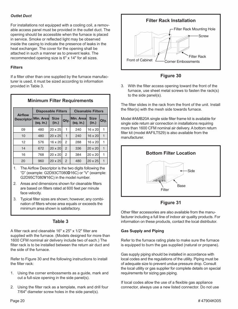
3. With the filter access opening toward the front of thefurnace, use sheet metal screws to fasten the rack(s)to the side panel(s).
The filter slides in the rack from the front of the unit. Installthe filter(s) with the mesh side towards furnace.
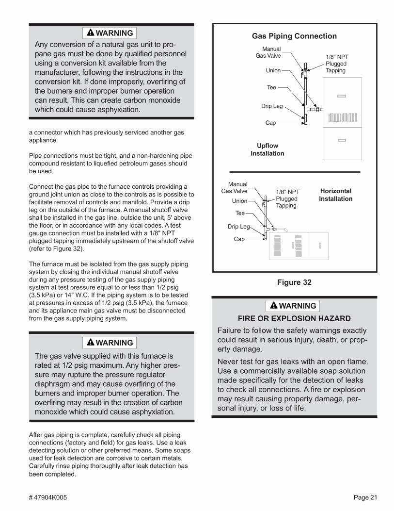
Model #AMB20A single side filter frame kit is available forsingle side return air connection in installations requiringmore than 1600 CFM nominal air delivery. A bottom returnfilter kit (model #AFILT529) is also available from themanufacturer.
Outlet Duct
For installations not equipped with a cooling coil, a remov-able access panel must be provided in the outlet duct. Theopening should be accessible when the furnace is placedin service. Smoke or reflected light may be observedinside the casing to indicate the presence of leaks in theheat exchanger. The cover for the opening shall beattached in such a manner as to prevent leaks. Therecommended opening size is 6" x 14" for all sizes.
Filters
If a filter other than one supplied by the furnace manufac-turer is used, it must be sized according to informationprovided in Table 3.
A filter rack and cleanable 16" x 25" x 1/2" filter aresupplied with the furnace. (Models designed for more than1600 CFM nominal air delivery include two of each.) Thefilter rack is to be installed between the return air duct andthe side of the furnace.
Refer to Figure 30 and the following instructions to installthe filter rack:
1. Using the corner embossments as a guide, mark andcut a full-size opening in the side panel(s).
2. Using the filter rack as a template, mark and drill four7/64" diameter screw holes in the side panel(s).
Table 3
Minimum Filter Requirements
1. The Airflow Descriptor is the two digits following the“D” (example: G2D93CT080D16C) or “V” (example:G2D95CT080V16C) in the model number.
2. Areas and dimensions shown for cleanable filtersare based on filters rated at 600 feet per minuteface velocity.
3. Typical filter sizes are shown; however, any combi-nation of filters whose area equals or exceeds theminimum area shown is satisfactory.
wolfriArotpircseD
sretliFelbasopsiD sretliFelbanaelC
aerA.niM).ni.qs(
eziS).ni(
.ytQaerA.niM).ni.qs(
eziS).ni(
.ytQ
90 084 52x02 1 042 02x61 1
01 084 52x02 1 042 02x61 1
21 675 02x61 2 882 02x61 1
41 276 02x02 2 633 02x02 1
61 867 02x02 2 483 02x02 1
02 069 52x02 2 084 52x02 1
Other filter accessories are also available from the manu-facturer including a full line of indoor air quality products. Forinformation on these products, contact the local distributor.
Gas Supply and Piping
Refer to the furnace rating plate to make sure the furnaceis equipped to burn the gas supplied (natural or propane).
Gas supply piping should be installed in accordance withlocal codes and the regulations of the utility. Piping must beof adequate size to prevent undue pressure drop. Consultthe local utility or gas supplier for complete details on specialrequirements for sizing gas piping.
If local codes allow the use of a flexible gas applianceconnector, always use a new listed connector. Do not use
Figure 31
Bottom Filter Location
FilterBase
Side
# 47904K005 Page 21
a connector which has previously serviced another gasappliance.
Pipe connections must be tight, and a non-hardening pipecompound resistant to liquefied petroleum gases shouldbe used.
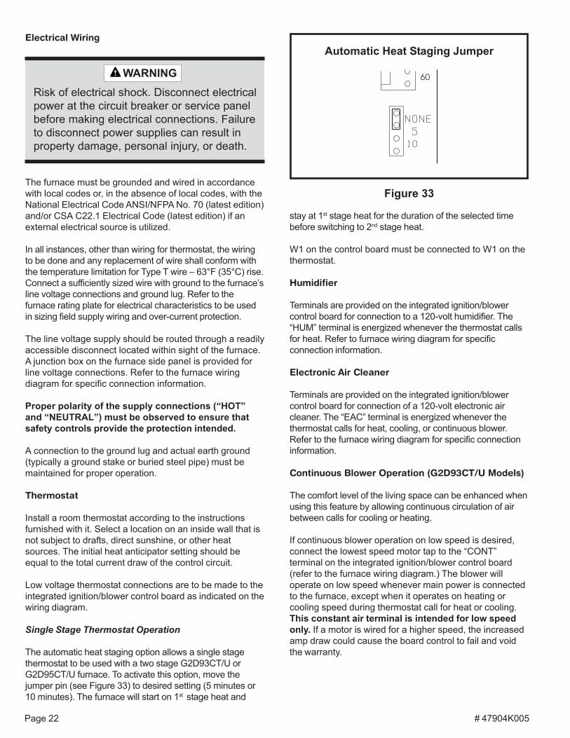
Connect the gas pipe to the furnace controls providing aground joint union as close to the controls as is possible tofacilitate removal of controls and manifold. Provide a dripleg on the outside of the furnace. A manual shutoff valveshall be installed in the gas line, outside the unit, 5' abovethe floor, or in accordance with any local codes. A testgauge connection must be installed with a 1/8" NPTplugged tapping immediately upstream of the shutoff valve(refer to Figure 32).
The furnace must be isolated from the gas supply pipingsystem by closing the individual manual shutoff valveduring any pressure testing of the gas supply pipingsystem at test pressure equal to or less than 1/2 psig(3.5 kPa) or 14" W.C. If the piping system is to be testedat pressures in excess of 1/2 psig (3.5 kPa), the furnaceand its appliance main gas valve must be disconnectedfrom the gas supply piping system.
After gas piping is complete, carefully check all pipingconnections (factory and field) for gas leaks. Use a leakdetecting solution or other preferred means. Some soapsused for leak detection are corrosive to certain metals.Carefully rinse piping thoroughly after leak detection hasbeen completed.
Any conversion of a natural gas unit to pro-pane gas must be done by qualified personnelusing a conversion kit available from themanufacturer, following the instructions in theconversion kit. If done improperly, overfiring ofthe burners and improper burner operationcan result. This can create carbon monoxidewhich could cause asphyxiation.
WARNING Gas Piping Connection
Figure 32
ManualGas Valve
Union
Tee
Drip Leg
Cap
1/8" NPTPluggedTapping
UpflowInstallation
HorizontalInstallation
The gas valve supplied with this furnace israted at 1/2 psig maximum. Any higher pres-sure may rupture the pressure regulatordiaphragm and may cause overfiring of theburners and improper burner operation. Theoverfiring may result in the creation of carbonmonoxide which could cause asphyxiation.
WARNINGFailure to follow the safety warnings exactlycould result in serious injury, death, or prop-erty damage.Never test for gas leaks with an open flame.Use a commercially available soap solutionmade specifically for the detection of leaksto check all connections. A fire or explosionmay result causing property damage, per-sonal injury, or loss of life.
WARNINGFIRE OR EXPLOSION HAZARD
# 47904K005Page 22
Automatic Heat Staging Jumper
Figure 33The furnace must be grounded and wired in accordancewith local codes or, in the absence of local codes, with theNational Electrical Code ANSI/NFPA No. 70 (latest edition)and/or CSA C22.1 Electrical Code (latest edition) if anexternal electrical source is utilized.
In all instances, other than wiring for thermostat, the wiringto be done and any replacement of wire shall conform withthe temperature limitation for Type T wire – 63°F (35°C) rise.Connect a sufficiently sized wire with ground to the furnace’sline voltage connections and ground lug. Refer to thefurnace rating plate for electrical characteristics to be usedin sizing field supply wiring and over-current protection.
The line voltage supply should be routed through a readilyaccessible disconnect located within sight of the furnace.A junction box on the furnace side panel is provided forline voltage connections. Refer to the furnace wiringdiagram for specific connection information.
Proper polarity of the supply connections (“HOT”and “NEUTRAL”) must be observed to ensure thatsafety controls provide the protection intended.
A connection to the ground lug and actual earth ground(typically a ground stake or buried steel pipe) must bemaintained for proper operation.
Thermostat
Install a room thermostat according to the instructionsfurnished with it. Select a location on an inside wall that isnot subject to drafts, direct sunshine, or other heatsources. The initial heat anticipator setting should beequal to the total current draw of the control circuit.
Low voltage thermostat connections are to be made to theintegrated ignition/blower control board as indicated on thewiring diagram.
Single Stage Thermostat Operation
The automatic heat staging option allows a single stagethermostat to be used with a two stage G2D93CT/U orG2D95CT/U furnace. To activate this option, move thejumper pin (see Figure 33) to desired setting (5 minutes or10 minutes). The furnace will start on 1st stage heat and
Electrical Wiring
Risk of electrical shock. Disconnect electricalpower at the circuit breaker or service panelbefore making electrical connections. Failureto disconnect power supplies can result inproperty damage, personal injury, or death.
WARNING
stay at 1st stage heat for the duration of the selected timebefore switching to 2nd stage heat.
W1 on the control board must be connected to W1 on thethermostat.
Humidifier
Terminals are provided on the integrated ignition/blowercontrol board for connection to a 120-volt humidifier. The“HUM” terminal is energized whenever the thermostat callsfor heat. Refer to furnace wiring diagram for specificconnection information.
Electronic Air Cleaner
Terminals are provided on the integrated ignition/blowercontrol board for connection of a 120-volt electronic aircleaner. The “EAC” terminal is energized whenever thethermostat calls for heat, cooling, or continuous blower.Refer to the furnace wiring diagram for specific connectioninformation.
Continuous Blower Operation (G2D93CT/U Models)
The comfort level of the living space can be enhanced whenusing this feature by allowing continuous circulation of airbetween calls for cooling or heating.
If continuous blower operation on low speed is desired,connect the lowest speed motor tap to the “CONT”terminal on the integrated ignition/blower control board(refer to the furnace wiring diagram.) The blower willoperate on low speed whenever main power is connectedto the furnace, except when it operates on heating orcooling speed during thermostat call for heat or cooling.This constant air terminal is intended for low speedonly. If a motor is wired for a higher speed, the increasedamp draw could cause the board control to fail and voidthe warranty.
# 47904K005 Page 23
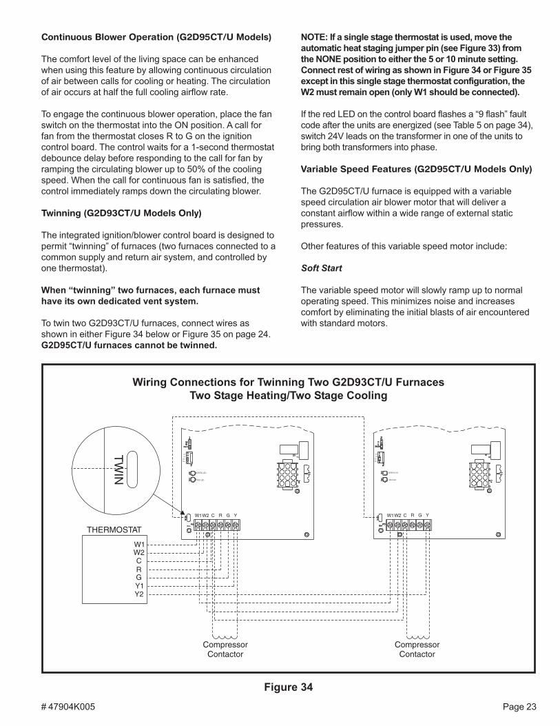
NOTE: If a single stage thermostat is used, move theautomatic heat staging jumper pin (see Figure 33) fromthe NONE position to either the 5 or 10 minute setting.Connect rest of wiring as shown in Figure 34 or Figure 35except in this single stage thermostat configuration, theW2 must remain open (only W1 should be connected).
If the red LED on the control board flashes a “9 flash” faultcode after the units are energized (see Table 5 on page 34),switch 24V leads on the transformer in one of the units tobring both transformers into phase.
Variable Speed Features (G2D95CT/U Models Only)
The G2D95CT/U furnace is equipped with a variablespeed circulation air blower motor that will deliver aconstant airflow within a wide range of external staticpressures.
Other features of this variable speed motor include:
Soft Start
The variable speed motor will slowly ramp up to normaloperating speed. This minimizes noise and increasescomfort by eliminating the initial blasts of air encounteredwith standard motors.
Continuous Blower Operation (G2D95CT/U Models)
The comfort level of the living space can be enhancedwhen using this feature by allowing continuous circulationof air between calls for cooling or heating. The circulationof air occurs at half the full cooling airflow rate.
To engage the continuous blower operation, place the fanswitch on the thermostat into the ON position. A call forfan from the thermostat closes R to G on the ignitioncontrol board. The control waits for a 1-second thermostatdebounce delay before responding to the call for fan byramping the circulating blower up to 50% of the coolingspeed. When the call for continuous fan is satisfied, thecontrol immediately ramps down the circulating blower.
Twinning (G2D93CT/U Models Only)
The integrated ignition/blower control board is designed topermit “twinning” of furnaces (two furnaces connected to acommon supply and return air system, and controlled byone thermostat).
When “twinning” two furnaces, each furnace musthave its own dedicated vent system.
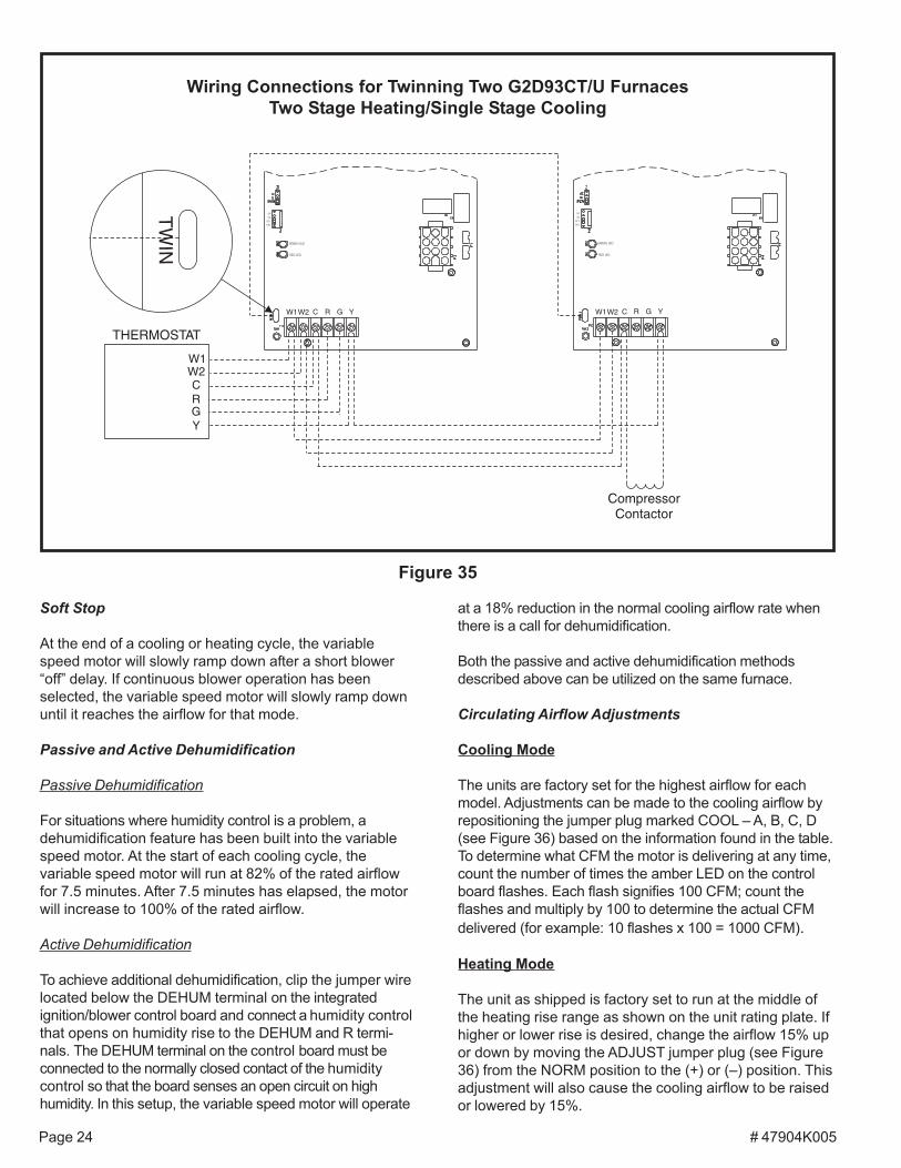
To twin two G2D93CT/U furnaces, connect wires asshown in either Figure 34 below or Figure 35 on page 24.G2D95CT/U furnaces cannot be twinned.
Figure 34
Wiring Connections for Twinning Two G2D93CT/U FurnacesTwo Stage Heating/Two Stage Cooling
# 47904K005Page 24
Soft Stop
At the end of a cooling or heating cycle, the variablespeed motor will slowly ramp down after a short blower“off” delay. If continuous blower operation has beenselected, the variable speed motor will slowly ramp downuntil it reaches the airflow for that mode.
Passive and Active Dehumidification
Passive Dehumidification
For situations where humidity control is a problem, adehumidification feature has been built into the variablespeed motor. At the start of each cooling cycle, thevariable speed motor will run at 82% of the rated airflowfor 7.5 minutes. After 7.5 minutes has elapsed, the motorwill increase to 100% of the rated airflow.
Active Dehumidification
To achieve additional dehumidification, clip the jumper wirelocated below the DEHUM terminal on the integratedignition/blower control board and connect a humidity controlthat opens on humidity rise to the DEHUM and R termi-nals. The DEHUM terminal on the control board must beconnected to the normally closed contact of the humiditycontrol so that the board senses an open circuit on highhumidity. In this setup, the variable speed motor will operate
Figure 35
Wiring Connections for Twinning Two G2D93CT/U FurnacesTwo Stage Heating/Single Stage Cooling
at a 18% reduction in the normal cooling airflow rate whenthere is a call for dehumidification.
Both the passive and active dehumidification methodsdescribed above can be utilized on the same furnace.
Circulating Airflow Adjustments
Cooling Mode
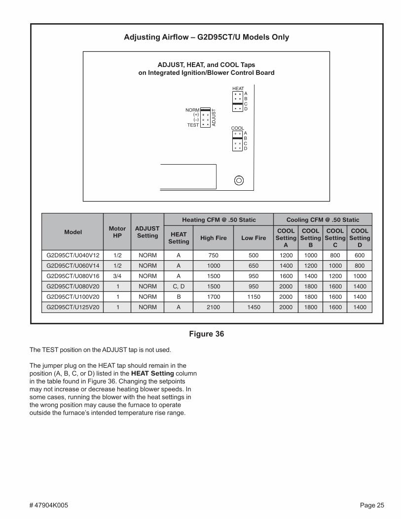
The units are factory set for the highest airflow for eachmodel. Adjustments can be made to the cooling airflow byrepositioning the jumper plug marked COOL – A, B, C, D(see Figure 36) based on the information found in the table.To determine what CFM the motor is delivering at any time,count the number of times the amber LED on the controlboard flashes. Each flash signifies 100 CFM; count theflashes and multiply by 100 to determine the actual CFMdelivered (for example: 10 flashes x 100 = 1000 CFM).
Heating Mode
The unit as shipped is factory set to run at the middle ofthe heating rise range as shown on the unit rating plate. Ifhigher or lower rise is desired, change the airflow 15% upor down by moving the ADJUST jumper plug (see Figure36) from the NORM position to the (+) or (–) position. Thisadjustment will also cause the cooling airflow to be raisedor lowered by 15%.
# 47904K005 Page 25
Figure 36
Adjusting Airflow – G2D95CT/U Models Only
ADJUST, HEAT, and COOL Tapson Integrated Ignition/Blower Control Board
ledoMrotoM
PHTSUJDAgnitteS
citatS05.@MFCgnitaeH citatS05.@MFCgnilooC
TAEHgnitteS
eriFhgiH eriFwoLLOOCgnitteS
A
LOOCgnitteS
B
LOOCgnitteS
C
LOOCgnitteS
D
21V040U/TC59D2G 2/1 MRON A 057 005 0021 0001 008 006
41V060U/TC59D2G 2/1 MRON A 0001 056 0041 0021 0001 008
61V080U/TC59D2G 4/3 MRON A 0051 059 0061 0041 0021 0001
02V080U/TC59D2G 1 MRON D,C 0051 059 0002 0081 0061 0041
02V001U/TC59D2G 1 MRON B 0071 0511 0002 0081 0061 0041
02V521U/TC59D2G 1 MRON A 0012 0541 0002 0081 0061 0041
The TEST position on the ADJUST tap is not used.
The jumper plug on the HEAT tap should remain in theposition (A, B, C, or D) listed in the HEAT Setting columnin the table found in Figure 36. Changing the setpointsmay not increase or decrease heating blower speeds. Insome cases, running the blower with the heat settings inthe wrong position may cause the furnace to operateoutside the furnace’s intended temperature rise range.
# 47904K005Page 26
1. Set the room thermostat to lowest setting.
2. Remove burner access door.
START-UP
These furnaces are equipped with an ignition devicewhich automatically lights the burners. Do not try to lightthe burners by hand.
Before operating, smell all around the appliance area forgas. Be sure to smell next to the floor because some gasis heavier than air and will settle on the floor.
What to do if you smell gas:
• Do not try to light any appliances.
• Extinguish any open flame.
• Do not touch any electric switch; do not use anyphone in your building.
• Immediately call your gas supplier from a neighbor’sphone. Follow the gas supplier’s instructions.
• If you cannot reach your gas supplier, call the firedepartment.
Do not use this furnace if any part has been under water.Immediately call a qualified service technician to inspectthe furnace and to replace any part of the control systemand gas control which has been under water.
IMPORTANT: Refer to the Lighting Instruction label onthe furnace for instructions on operating the specificcontrols used on your unit.
To Start Furnace:
Lighting Instructions
For Your Safety, Read Before Operating
Be sure the manual gas control has been inthe “OFF” position for at least 5 minutesbefore starting the unit. Do not attempt tomanually light the burners.
CAUTION
Should overheating occur or the gas supplyfail to shut off, shut off the manual gas valveto the appliance before shutting off theelectrical supply.
WARNING
3. Move the gas control knob to the “ON” position. Useonly your hand to turn the gas control knob; never usetools. If the knob will not turn by hand, don’t try torepair it; call a qualified service technician. Force orattempted repair may result in a fire or explosion.
4. Replace the burner access door.
5. Turn on the electrical power to the furnace.
6. Set the room thermostat to a point above roomtemperature to light the burners. After the burnershave ignited, set the room thermostat to desiredtemperature.
To Shut Down Furnace:
1. Set the room thermostat to the lowest setting.
2. Turn off all electric power to the furnace.
3. Remove burner access door.
4. Shut off the gas by moving the gas control knob to the“OFF” position.
5. Replace the burner access door.
If you do not follow these instructions exactly,a fire or explosion may result causing prop-erty damage, personal injury, or loss of life.
WARNING
# 47904K005 Page 27
Fan On
A call for fan from the thermostat closes R to G on thecontrol board. The control waits for a 1-second thermostatdebounce delay before responding by energizing the lowheat speed blower. When the call for fan is turned off, thecontrol de-energizes the blower.
Cooling
During a call for cooling, the thermostat energizes the R-Ycircuit of the control board. After a 1-second cooling “on”delay, the control energizes the cooling fan speed. If the fanis already energized, it remains running and does not de-energize for the 1-second cooling fan “on” delay.
The call for cooling has priority over continuous fanoperation while a call for heating has priority over both acall for cooling or continuous fan. Ignition lockouts for anyreason do not affect cooling operation.
As cooling demand is met, the thermostat de-energizesthe R-Y circuit of the control board. After a 60-secondcooling “off” delay, the control de-energizes the coolingspeed fan. At the end of the cooling “off” delay period, thecontrol returns to the standby mode.
Sequence of Operation (G2D95CT/U Models)
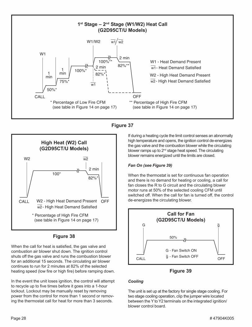
Heating (see Figures 37 and 38 on page 28)
On a call for heat from the room thermostat, the ignitioncontrol performs a 1-second self-check. Upon confirma-tion that the pressure switch contacts are in an openposition, the ignition control energizes the combustionblower on high speed. The control then checks for ad-equate combustion air by making sure the low-fire pres-sure switch contacts are closed.
The igniter energizes and is allowed to warm up for7 seconds before the gas valve energizes on 1st stage andburners ignite. 45 seconds after the control confirmsignition has occurred, the control drops the combustionblower to low speed.
The circulating blower ramps up to 50% of 1st stage heatspeed and operates at that speed for one minute (includingramp up time), then at 75% of 1st stage heat speed for anadditional minute. After that, the circulating blower operatesat full 1st stage heat speed until either the heat call issatisfied or the thermostat initiates a call for 2nd stage heat.On a call for 2nd stage heat, the control energizes thecirculating air blower on full CFM 2nd stage heat.
If the automatic heat staging option is being used (seeSingle Stage Thermostat Operation on page 22), thefurnace does not switch to 2nd stage heat in response to acall from the thermostat but instead operates at 1st stageheat for the duration of the selected time before automati-cally switching to 2nd stage heat.
OPERATION
Sequence of Operation (G2D93CT/U Models)
Heating
When the control is in standby mode, it continually monitorsthermostat input, rollout switch, and flame sense.
On a call for 1st stage heat, W1 and R are connected. Thecontrol verifies the limit switch is closed and both low andhigh pressure switches are open. The control always startson low-fire and ignores 2nd stage call for 30 seconds.
The induced draft blower is energized on high speed andwaits for the low pressure switch to close. The inducerremains on high speed and begins a pre-purge periodwhen the low pressure switch closes. After a 15-secondpre-purge, the control energizes the hot surface igniter fora period of 7 seconds (15 seconds on retries) before thegas valve is energized on 1st stage and burners ignite.After a 30-second blower “on” delay, the control energizesthe low heat circulating air blower. Fifteen seconds afterthe circulating air blower energizes, the combustion airblower switches to low speed and runs at that speed untilthe thermostat is satisfied.
If the 1st stage is not sufficient to satisfy the heatingdemand, the room thermostat initiates call for the 2nd
stage heat (W1 and W2). The control energizes thecombustion blower on high speed and confirms the high-fire pressure switch contacts are closed. If the contactsare closed, the gas valve energizes on the 2nd stage andthe high-heat circulating air blower is energized.
If the automatic heat staging option is being used (seeSingle Stage Thermostat Operation on page 22), thefurnace does not switch to 2nd stage heat in response to acall from the thermostat but instead operates at 1st stageheat for the duration of the selected time before automati-cally switching to 2nd stage heat.
When the 2nd stage heat is satisfied, the control shuts offthe gas valve and runs the combustion blower for a post-purge period of 15 seconds. The circulating air blowercontinues to run according until the selected blower “off”delay time (factory shipped at 120 seconds) ends.
In the event the unit loses ignition, the control will attemptto recycle up to five times before it goes into a 1-hourlockout. Lockout may be manually reset by removingpower from the control for more than 1 second or remov-ing the thermostat call for heat for more than 3 seconds.
If during a heating cycle the limit control senses anabnormally high temperature and opens, the circulating airblower is energized on high speed and continues to runwhile the limit is still open.
# 47904K005Page 28
If during a heating cycle the limit control senses an abnormallyhigh temperature and opens, the ignition control de-energizesthe gas valve and the combustion blower while the circulatingblower ramps up to 2nd stage heat speed. The circulatingblower remains energized until the limits are closed.
Fan On (see Figure 39)
When the thermostat is set for continuous fan operationand there is no demand for heating or cooling, a call forfan closes the R to G circuit and the circulating blowermotor runs at 50% of the selected cooling CFM untilswitched off. When the call for fan is turned off, the controlde-energizes the circulating blower.
Cooling
The unit is set up at the factory for single stage cooling. Fortwo stage cooling operation, clip the jumper wire locatedbetween the Y to Y2 terminals on the integrated ignition/blower control board.
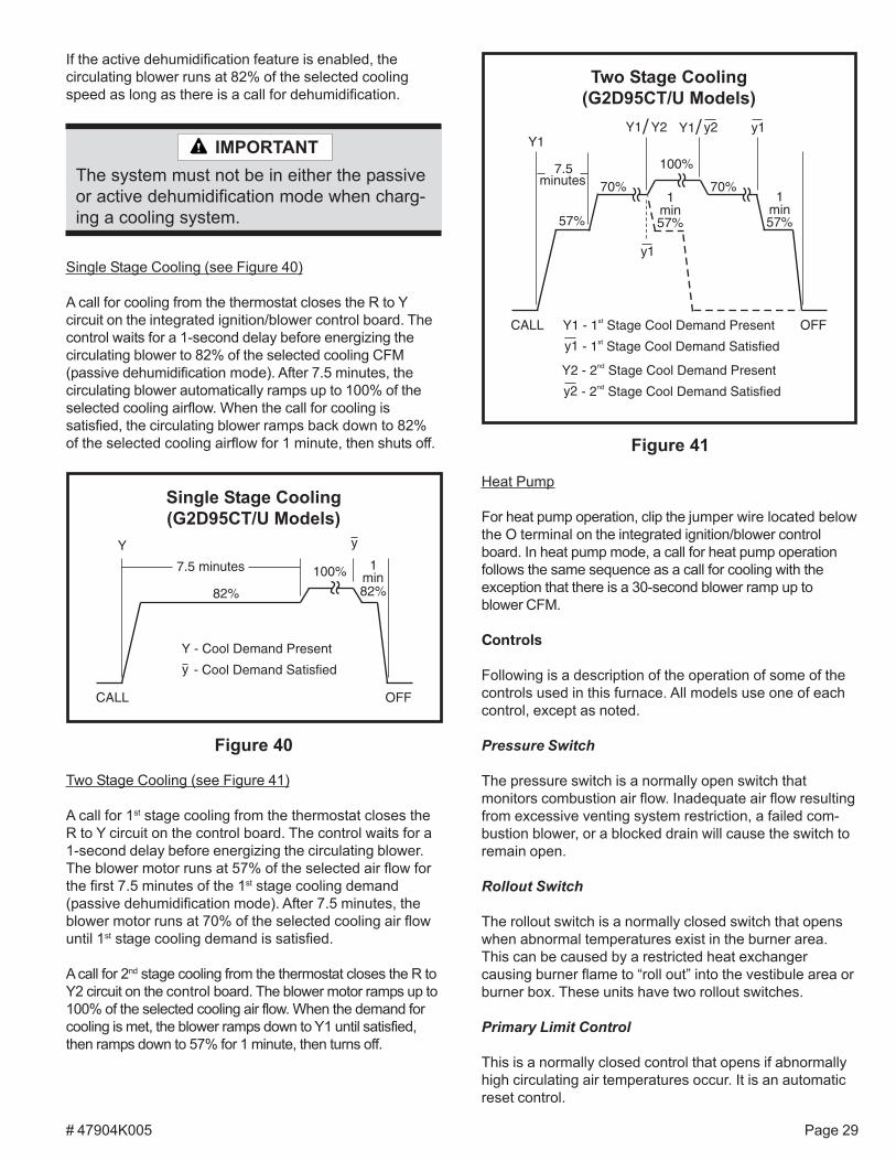
When the call for heat is satisfied, the gas valve andcombustion air blower shut down. The ignition controlshuts off the gas valve and runs the combustion blowerfor an additional 15 seconds. The circulating air blowercontinues to run for 2 minutes at 82% of the selectedheating speed (low fire or high fire) before ramping down.
In the event the unit loses ignition, the control will attemptto recycle up to five times before it goes into a 1-hourlockout. Lockout may be manually reset by removingpower from the control for more than 1 second or remov-ing the thermostat call for heat for more than 3 seconds.
High Heat (W2) Call(G2D95CT/U Models)
W2
100*82%*
2 min
CALL OFFW2 - High Heat Demand Present- High Heat Demand Satisfiedw2
* Percentage of High Fire CFM(see table in Figure 14 on page 17)
w2
Figure 38
Call for Fan(G2D95CT/U Models)
Figure 39
G g
50%
CALL OFF
G - Fan Switch ON
- Fan Switch OFFg
Figure 37
1st Stage – 2nd Stage (W1/W2) Heat Call(G2D95CT/U Models)
W1
100%*
CALL
W2 - High Heat Demand Present- High Heat Demand Satisfiedw2
50%*
75%*
** Percentage of High Fire CFM(see table in Figure 14 on page 17)
1min
W1 - Heat Demand Present- Heat Demand Satisfiedw1
* Percentage of Low Fire CFM(see table in Figure 14 on page 17)
100%**82%**
2 min
OFF
W1/W2 w1 w2
82%*
2 min
w1
1min
# 47904K005 Page 29
Heat Pump
For heat pump operation, clip the jumper wire located belowthe O terminal on the integrated ignition/blower controlboard. In heat pump mode, a call for heat pump operationfollows the same sequence as a call for cooling with theexception that there is a 30-second blower ramp up toblower CFM.
Controls
Following is a description of the operation of some of thecontrols used in this furnace. All models use one of eachcontrol, except as noted.
Pressure Switch
The pressure switch is a normally open switch thatmonitors combustion air flow. Inadequate air flow resultingfrom excessive venting system restriction, a failed com-bustion blower, or a blocked drain will cause the switch toremain open.
Rollout Switch
The rollout switch is a normally closed switch that openswhen abnormal temperatures exist in the burner area.This can be caused by a restricted heat exchangercausing burner flame to “roll out” into the vestibule area orburner box. These units have two rollout switches.
Primary Limit Control
This is a normally closed control that opens if abnormallyhigh circulating air temperatures occur. It is an automaticreset control.
The system must not be in either the passiveor active dehumidification mode when charg-ing a cooling system.
IMPORTANT
If the active dehumidification feature is enabled, thecirculating blower runs at 82% of the selected coolingspeed as long as there is a call for dehumidification.
Two Stage Cooling (see Figure 41)
A call for 1st stage cooling from the thermostat closes theR to Y circuit on the control board. The control waits for a1-second delay before energizing the circulating blower.The blower motor runs at 57% of the selected air flow forthe first 7.5 minutes of the 1st stage cooling demand(passive dehumidification mode). After 7.5 minutes, theblower motor runs at 70% of the selected cooling air flowuntil 1st stage cooling demand is satisfied.
A call for 2nd stage cooling from the thermostat closes the R toY2 circuit on the control board. The blower motor ramps up to100% of the selected cooling air flow. When the demand forcooling is met, the blower ramps down to Y1 until satisfied,then ramps down to 57% for 1 minute, then turns off.
Two Stage Cooling(G2D95CT/U Models)
Figure 41
Y1
y1
57%
100%
CALL OFF
7.5minutes 70%
Y1 - 1 Stage Cool Demand Presentst
- Demand Satisfied1 Stage Coolsty1
Y2 - 2 Stage Cool Demand Presentnd
- 2 Demand Satisfiednd Stage Cooly2
1min
70%
Y1 y2/Y1/ Y2 y1
57%
1min57%
Single Stage Cooling (see Figure 40)
A call for cooling from the thermostat closes the R to Ycircuit on the integrated ignition/blower control board. Thecontrol waits for a 1-second delay before energizing thecirculating blower to 82% of the selected cooling CFM(passive dehumidification mode). After 7.5 minutes, thecirculating blower automatically ramps up to 100% of theselected cooling airflow. When the call for cooling issatisfied, the circulating blower ramps back down to 82%of the selected cooling airflow for 1 minute, then shuts off.
7.5 minutes
Y y
82%
100%
82%
1min
CALL OFF
Y - Cool Demand Present
- Cool Demand Satisfiedy
Single Stage Cooling(G2D95CT/U Models)
Figure 40
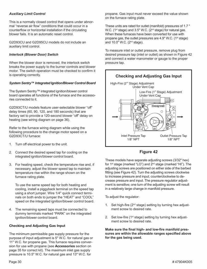
# 47904K005Page 30
Checking and Adjusting Gas Input
Figure 42
OFF
ON
Inlet Pressure Tap1/8" NPT
Outlet Pressure Tap1/8" NPT
High-Fire (2 Stage) AdjustmentUnder Vent Cap
nd
Low-Fire (1 Stage) AdjustmentUnder Vent Cap
st
Auxiliary Limit Control
This is a normally closed control that opens under abnor-mal “reverse air flow” conditions that could occur in acounterflow or horizontal installation if the circulatingblower fails. It is an automatic reset control.
G2D93CU and G2D95CU models do not include anauxiliary limit control.
Interlock (Blower Door) Switch
When the blower door is removed, the interlock switchbreaks the power supply to the burner controls and blowermotor. The switch operation must be checked to confirm itis operating correctly.
System Sentry™ Integrated Ignition/Blower Control Board
The System Sentry™ integrated ignition/blower controlboard operates all functions of the furnace and the accesso-ries connected to it.
G2D93CT/U models feature user-selectable blower “off”delay times (60, 90, 120, and 180 seconds) that arefactory set to provide a 120-second blower “off” delay onheating (see wiring diagram on page 36).
Refer to the furnace wiring diagram while using thefollowing procedure to the change motor speed on aG2D93CT/U furnace:
1. Turn off electrical power to the unit.
2. Connect the desired speed tap for cooling on theintegrated ignition/blower control board.
3. For heating speed, check the temperature rise and, ifnecessary, adjust the blower speed tap to maintaintemperature rise within the range shown on thefurnace rating plate.
To use the same speed tap for both heating andcooling, install a piggyback terminal on the speed tapusing a short jumper. Wire 1/4" quick connect termi-nals on both ends to jumper the “HEAT” and “COOL”speed on the integrated ignition/blower control board.
4. The remaining speed taps must be connected todummy terminals marked “PARK” on the integratedignition/blower control board.
Checking and Adjusting Gas Input
The minimum permissible gas supply pressure for thepurpose of input adjustment is 5" W.C. for natural gas or11" W.C. for propane gas. This furnace requires conver-sion for use with propane (see Accessories section onpage 35 for correct kit). The maximum inlet gas supplypressure is 10.5" W.C. for natural gas and 13" W.C. for
propane. Gas input must never exceed the value shownon the furnace rating plate.
These units are rated for outlet (manifold) pressures of 1.7 "W.C. (1st stage) and 3.5" W.C. (2nd stage) for natural gas.When these furnaces have been converted for use withpropane gas, the outlet pressures are 4.9" W.C. (1st stage)and 10.0" W.C. (2nd stage).
To measure inlet or outlet pressure, remove plug fromdesired pressure tap (inlet or outlet) as shown in Figure 42and connect a water manometer or gauge to the properpressure tap.
These models have separate adjusting screws (3/32" hex)for 1st stage (marked “LO”) and 2nd stage (marked “HI”). Theadjusting screws are positioned on either side of the barbedfitting (see Figure 42). Turn the adjusting screws clockwiseto increase pressure and input; counterclockwise to de-crease pressure and input. The pressure regulator adjust-ment is sensitive; one turn of the adjusting screw will resultin a relatively large change in manifold pressure.
To adjust the regulator:
1. Set high-fire (2nd stage) setting by turning hex adjust-ment screw to desired rate.
2. Set low-fire (1st stage) setting by turning hex adjust-ment screw to desired rate.
Make sure the final high- and low-fire manifold pres-sures are within the allowable ranges specified abovefor the gas being used.
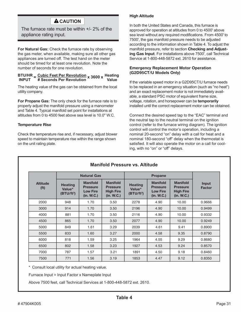
# 47904K005 Page 31
For Natural Gas: Check the furnace rate by observingthe gas meter, when available, making sure all other gasappliances are turned off. The test hand on the metershould be timed for at least one revolution. Note thenumber of seconds for one revolution.
x 3600 x= Cubic Feet Per RevolutionBTU/HR INPUT # Seconds Per Revolution
HeatingValue
The heating value of the gas can be obtained from the localutility company.
For Propane Gas: The only check for the furnace rate is toproperly adjust the manifold pressure using a manometerand Table 4. Typical manifold set point for installations ataltitudes from 0 to 4500 feet above sea level is 10.0" W.C.
Temperature Rise
Check the temperature rise and, if necessary, adjust blowerspeed to maintain temperature rise within the range shownon the unit rating plate.
The furnace rate must be within +/- 2% of theappliance rating input.
CAUTION
Manifold Pressure vs. Altitude
Table 4
* Consult local utility for actual heating value.
Furnace Input = Input Factor x Nameplate Input
Above 7500 feet, call Technical Services at 1-800-448-5872 ext. 2610.
edutitlA)tf(
saGlarutaN enaporP
tupnIrotcaF
gnitaeH*eulaVtf/UTB( 3)
dlofinaMerusserPeriFwoL).C.W.ni(
dlofinaMerusserPeriFhgiH).C.W.ni(
gnitaeH*eulaVtf/UTB( 3)
dlofinaMerusserPeriFwoL).C.W.ni(
dlofinaMerusserPeriFhgiH).C.W.ni(
0002 849 07.1 05.3 8722 09.4 00.01 6669.0
0003 419 07.1 05.3 6912 09.4 00.01 9949.0
0004 188 07.1 05.3 6112 09.4 00.01 2339.0
0054 568 07.1 05.3 7702 09.4 00.01 9429.0
0005 948 16.1 92.3 9302 16.4 14.9 0098.0
0055 338 06.1 72.3 0002 85.4 53.9 0978.0
0006 818 95.1 52.3 4691 55.4 92.9 0868.0
0056 208 85.1 32.3 7291 35.4 42.9 0758.0
0007 787 75.1 12.3 1981 05.4 81.9 0648.0
0057 177 65.1 91.3 3581 74.4 21.9 0538.0
High Altitude
In both the United States and Canada, this furnace isapproved for operation at altitudes from 0 to 4500' abovesea level without any required modifications. From 4500' to7500', the gas manifold pressure needs to be adjustedaccording to the information shown in Table 4. To adjust themanifold pressure, refer to section Checking and Adjust-ing Gas Input. For installations above 7500', call TechnicalService at 1-800-448-5872 ext. 2610 for assistance.
Emergency Replacement Motor Operation(G2D95CT/U Models Only)
If the variable speed motor in a G2D95CT/U furnace needsto be replaced in an emergency situation (such as “no heat”)and an exact replacement motor is not immediately avail-able, a standard PSC motor of equivalent frame size,voltage, rotation, and horsepower can be temporarilyinstalled until the correct replacement motor can be obtained.
Connect the desired speed tap to the “EAC” terminal andthe neutral tap to the neutral terminal on the ignitioncontrol (refer to the furnace wiring diagram). The ignitioncontrol will control the motor’s operation, including anominal 20-second “on” delay with a call for heat and anominal 180-second “off” delay when the thermostat issatisfied. It will also operate the motor on a call for cool-ing, with no “on” or “off” delays.

# 47904K005Page 32
Verify that the unit is operating at the desired speed andwithin the rise range as shown on the unit rating plate.
The correct replacement motor must be installed assoon as possible to ensure continued satisfactoryoperation of the furnace.
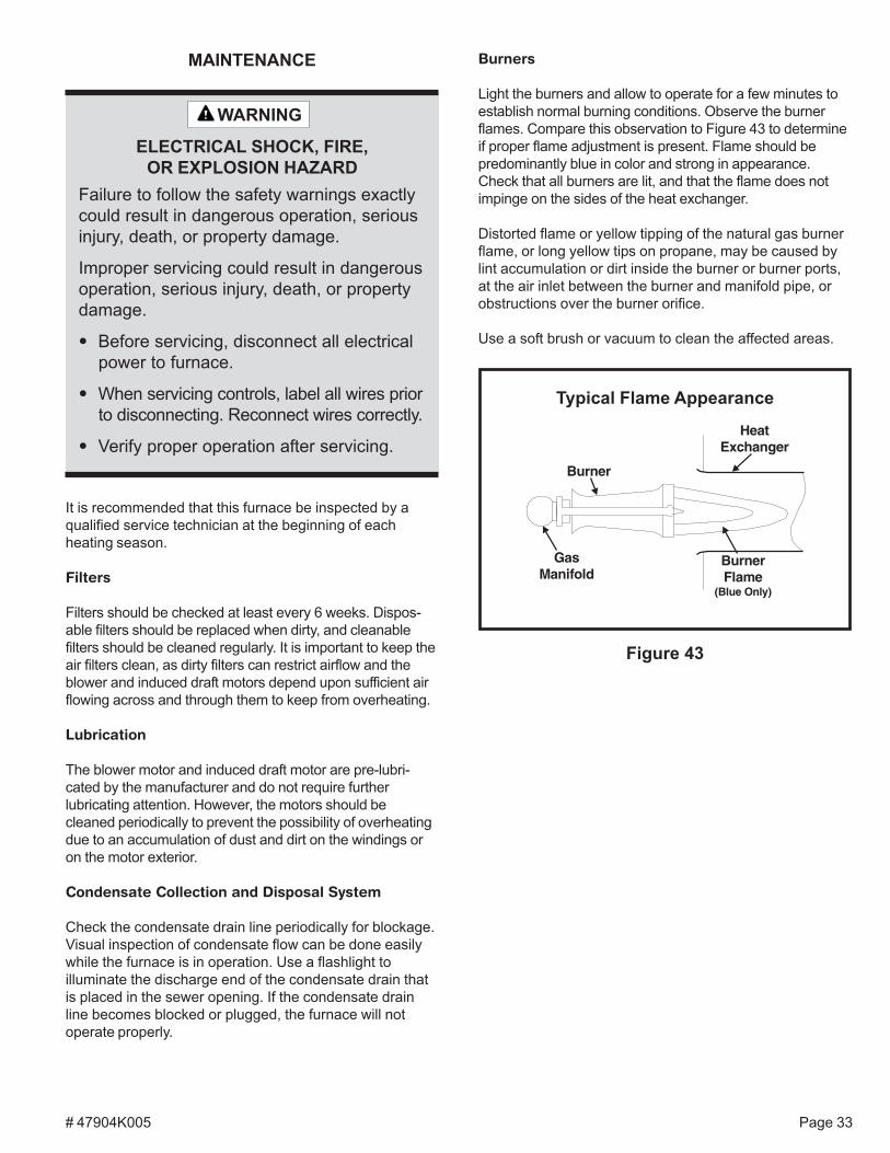
# 47904K005 Page 33
It is recommended that this furnace be inspected by aqualified service technician at the beginning of eachheating season.
Filters
Filters should be checked at least every 6 weeks. Dispos-able filters should be replaced when dirty, and cleanablefilters should be cleaned regularly. It is important to keep theair filters clean, as dirty filters can restrict airflow and theblower and induced draft motors depend upon sufficient airflowing across and through them to keep from overheating.
Lubrication
The blower motor and induced draft motor are pre-lubri-cated by the manufacturer and do not require furtherlubricating attention. However, the motors should becleaned periodically to prevent the possibility of overheatingdue to an accumulation of dust and dirt on the windings oron the motor exterior.
Condensate Collection and Disposal System
Check the condensate drain line periodically for blockage.Visual inspection of condensate flow can be done easilywhile the furnace is in operation. Use a flashlight toilluminate the discharge end of the condensate drain thatis placed in the sewer opening. If the condensate drainline becomes blocked or plugged, the furnace will notoperate properly.
MAINTENANCE Burners
Light the burners and allow to operate for a few minutes toestablish normal burning conditions. Observe the burnerflames. Compare this observation to Figure 43 to determineif proper flame adjustment is present. Flame should bepredominantly blue in color and strong in appearance.Check that all burners are lit, and that the flame does notimpinge on the sides of the heat exchanger.
Distorted flame or yellow tipping of the natural gas burnerflame, or long yellow tips on propane, may be caused bylint accumulation or dirt inside the burner or burner ports,at the air inlet between the burner and manifold pipe, orobstructions over the burner orifice.
Use a soft brush or vacuum to clean the affected areas.
Failure to follow the safety warnings exactlycould result in dangerous operation, seriousinjury, death, or property damage.
Improper servicing could result in dangerousoperation, serious injury, death, or propertydamage.
• Before servicing, disconnect all electricalpower to furnace.
• When servicing controls, label all wires priorto disconnecting. Reconnect wires correctly.
• Verify proper operation after servicing.
WARNING
ELECTRICAL SHOCK, FIRE,OR EXPLOSION HAZARD
Typical Flame Appearance
Figure 43
HeatExchanger
BurnerFlame
(Blue Only)
Burner
GasManifold
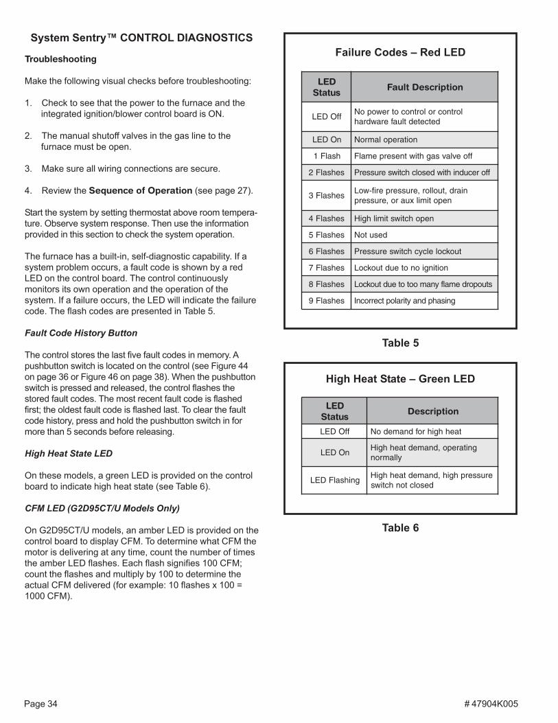
# 47904K005Page 34
System Sentry™ CONTROL DIAGNOSTICS
Troubleshooting
Make the following visual checks before troubleshooting:
1. Check to see that the power to the furnace and theintegrated ignition/blower control board is ON.
2. The manual shutoff valves in the gas line to thefurnace must be open.
3. Make sure all wiring connections are secure.
4. Review the Sequence of Operation (see page 27).
Start the system by setting thermostat above room tempera-ture. Observe system response. Then use the informationprovided in this section to check the system operation.
The furnace has a built-in, self-diagnostic capability. If asystem problem occurs, a fault code is shown by a redLED on the control board. The control continuouslymonitors its own operation and the operation of thesystem. If a failure occurs, the LED will indicate the failurecode. The flash codes are presented in Table 5.
Fault Code History Button
The control stores the last five fault codes in memory. Apushbutton switch is located on the control (see Figure 44on page 36 or Figure 46 on page 38). When the pushbuttonswitch is pressed and released, the control flashes thestored fault codes. The most recent fault code is flashedfirst; the oldest fault code is flashed last. To clear the faultcode history, press and hold the pushbutton switch in formore than 5 seconds before releasing.
High Heat State LED
On these models, a green LED is provided on the controlboard to indicate high heat state (see Table 6).
CFM LED (G2D95CT/U Models Only)
On G2D95CT/U models, an amber LED is provided on thecontrol board to display CFM. To determine what CFM themotor is delivering at any time, count the number of timesthe amber LED flashes. Each flash signifies 100 CFM;count the flashes and multiply by 100 to determine theactual CFM delivered (for example: 10 flashes x 100 =1000 CFM).
Failure Codes – Red LED
Table 5
High Heat State – Green LED
DELsutatS
noitpircseD
ffODEL taehhgihrofdnamedoN
nODELgnitarepo,dnamedtaehhgiH
yllamron
gnihsalFDELerusserphgih,dnamedtaehhgiH
desolctonhctiws
Table 6
DELsutatS
noitpircseDtluaF
ffODELlortnocrolortnocotrewopoN
detcetedtluaferawdrah
nODEL noitarepolamroN
hsalF1 ffoevlavsaghtiwtneserpemalF
sehsalF2 fforecudnihtiwdesolchctiwserusserP
sehsalF3niard,tuollor,erusserperif-woL
nepotimilxuaro,erusserp
sehsalF4 nepohctiwstimilhgiH
sehsalF5 desutoN
sehsalF6 tuokcolelcychctiwserusserP
sehsalF7 noitingionoteudtuokcoL
sehsalF8 stuopordemalfynamoototeudtuokcoL
sehsalF9 gnisahpdnaytiraloptcerrocnI
# 47904K005 Page 35
REPAIR PARTS
The following repair parts are available from the localdistributor. When ordering parts, include the completefurnace model number and serial number which areprinted on the rating plate located on the furnace.
Control Group
TransformerHigh limit controlAuxiliary limitGas valveIntegrated ignition/blower control boardFlame sensorPressure switches – 1st stage and 2nd stageBlower door interlock switchCombustion blower assemblyFlame rollout protector switchHot surface igniterInput choke
Heat Exchanger Group
Heat exchanger – primaryHeat exchanger – secondaryCondensate drain pan (header box)
Blower Group
Blower housing assemblyBlower wheelBlower mountBlower motorBlower motor mount
Burner Group
Gas manifoldBurner orificesBurners
Accessories
ALPKT583 Natural Gas to Propane Conversion KitANGKT556 Propane to Natural Gas Conversion KitAMB20A Single Side Filter Frame KitAFILT524 Side Return Filter KitAFILT529 Bottom Return Filter KitAFOSL443 Fossil Fuel KitACVK2 Concentric Vent Kit
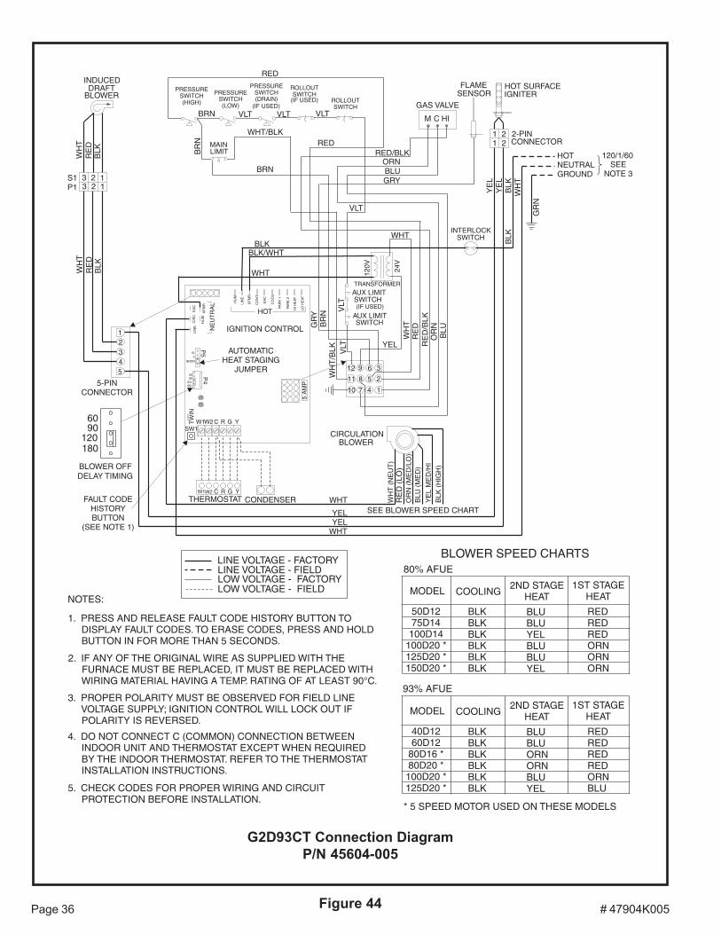
# 47904K005Page 36 Figure 44
G2D93CT Connection DiagramP/N 45604-005
5 A
MP
YC GRW1W2
LIN
EE
AC
XF
MR
CIR
C
HU
M
HU
M
XF
MR
LIN
E
PAR
K 1
CO
OL
EA
C
HI H
EAT
LO H
EAT
NE
UT
RA
L
HOT
IGNITION CONTROL
TRANSFORMER
INDUCEDDRAFT
BLOWER
INTERLOCKSWITCH
122 1
C HI
GAS VALVE
M
PRESSURESWITCH(LOW)
ROLLOUTSWITCH
(IF USED)
MAINLIMIT
PRESSURESWITCH(DRAIN)
(IF USED)
12 9 6 3
11 8 5 2
10 7 4 1
33
120V 24V
HOTNEUTRALGROUND
120/1/60SEE
NOTE 3
12345
BLK
RE
DW
HT
WH
TR
ED
BLK
5-PINCONNECTOR
W2 GR YW1
THERMOSTAT CONDENSER WHT
YELYEL
WHT
BLU
OR
NR
ED
/BLK
RE
DW
HT
YELV
LT
BR
NG
RY
BLKBLK/WHT
WHT
RED/BLK
YE
LY
EL
BLK
WH
T
ORNBLUGRY
GR
N
WHT/BLKRED
BRN
BLK
221
12-PINCONNECTOR
CIRCULATIONBLOWER
FLAMESENSOR
HOT SURFACEIGNITER
WH
T (
NE
UT
)R
ED
(LO
)
BLU
(M
ED
)O
RN
(M
ED
/LO
)
YE
L M
ED
/HI
BLK
(H
IGH
)
SEE BLOWER SPEED CHART
S1P1
ROLLOUTSWITCH
AUX LIMITSWITCH(IF USED)
AUX LIMITSWITCH
VLT
VLT
PRESSURESWITCH(HIGH)
RED
VLT VLTVLT
BR
N
BRN
WHT
CO
NT
PAR
K 2
TW
IN
NONE510
P5
1801209060 P
4
LOW VOLTAGE - FIELDLOW VOLTAGE - FACTORYLINE VOLTAGE - FIELDLINE VOLTAGE - FACTORY
SW1
FAULT CODEHISTORYBUTTON
(SEE NOTE 1)
AUTOMATICHEAT STAGING
JUMPER
BLOWER OFFDELAY TIMING
180120
9060
C
NOTES:
3. PROPER POLARITY MUST BE OBSERVED FOR FIELD LINEVOLTAGE SUPPLY; IGNITION CONTROL WILL LOCK OUT IFPOLARITY IS REVERSED.
1. PRESS AND RELEASE FAULT CODE HISTORY BUTTON TODISPLAY FAULT CODES. TO ERASE CODES, PRESS AND HOLDBUTTON IN FOR MORE THAN 5 SECONDS.
2. IF ANY OF THE ORIGINAL WIRE AS SUPPLIED WITH THEFURNACE MUST BE REPLACED, IT MUST BE REPLACED WITHWIRING MATERIAL HAVING A TEMP. RATING OF AT LEAST 90°C.
WH
T/B
LK
* 5 SPEED MOTOR USED ON THESE MODELS
BLOWER SPEED CHARTS
1ST STAGEHEATMODEL COOLING
2ND STAGEHEAT
BLUBLUYELBLUBLUYEL
BLKBLKBLKBLKBLKBLK
50D1275D14100D14
100D20 *125D20 *150D20 *
REDREDREDORNORNORN
1ST STAGEHEATMODEL COOLING
2ND STAGEHEAT
BLUBLUORNORNBLUYEL
BLKBLKBLKBLKBLKBLK
40D1260D12
80D16 *80D20 *100D20 *125D20 *
REDREDREDREDORNBLU
80% AFUE
93% AFUE
4. DO NOT CONNECT C (COMMON) CONNECTION BETWEENINDOOR UNIT AND THERMOSTAT EXCEPT WHEN REQUIREDBY THE INDOOR THERMOSTAT. REFER TO THE THERMOSTATINSTALLATION INSTRUCTIONS.
5. CHECK CODES FOR PROPER WIRING AND CIRCUITPROTECTION BEFORE INSTALLATION.
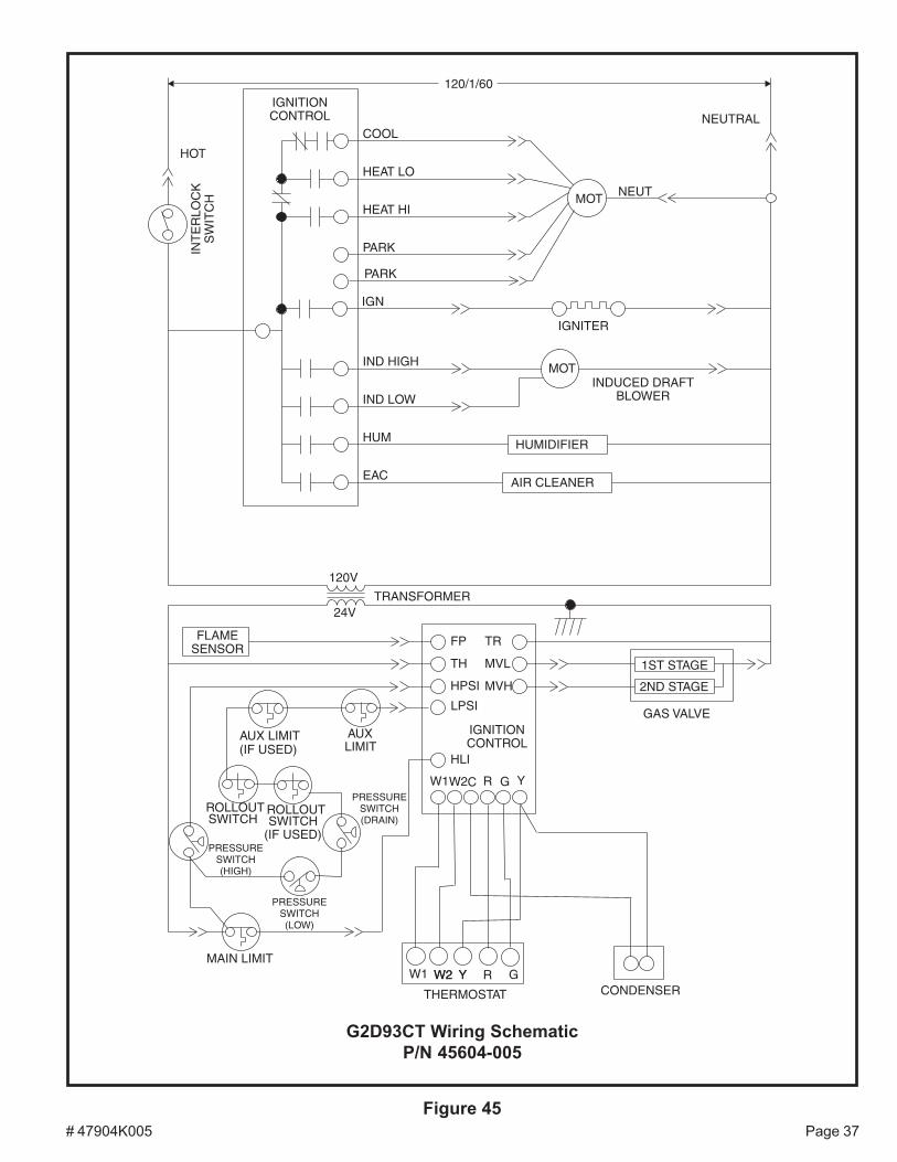
# 47904K005 Page 37Figure 45
G2D93CT Wiring SchematicP/N 45604-005
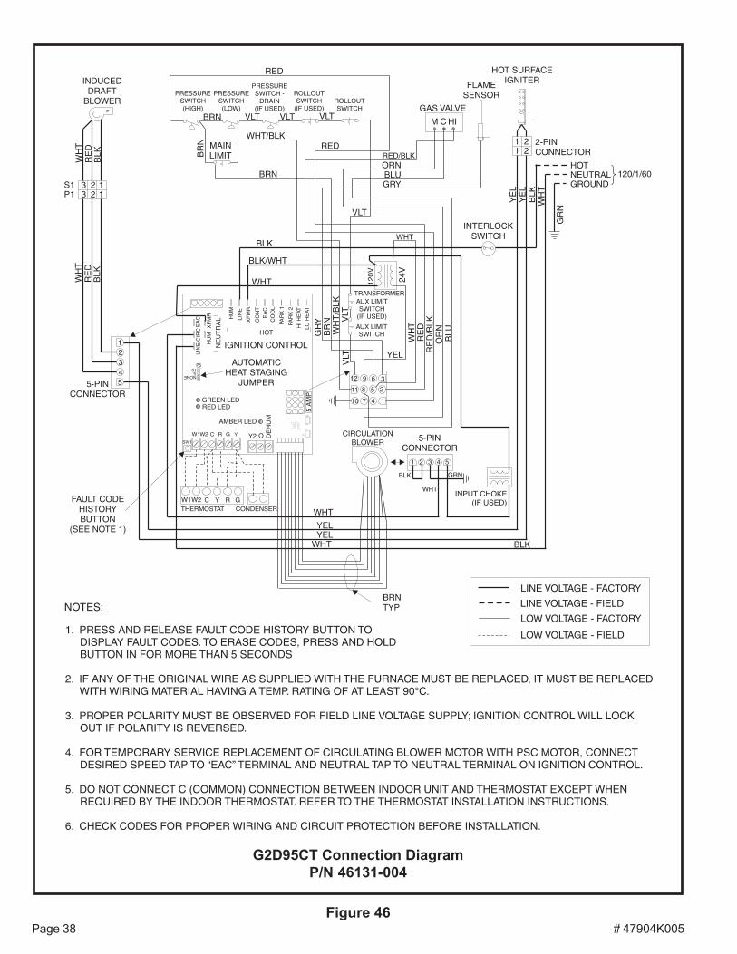
# 47904K005Page 38Figure 46
G2D95CT Connection DiagramP/N 46131-004
5 A
MP
IGNITION CONTROL
TRANSFORMER
INDUCEDDRAFT
BLOWER
INTERLOCKSWITCH
122 1
C HI
GAS VALVE
M
MAINLIMIT
12 9 6 3
11 8 5 2
10 7 4 1
33
120V
24V
HOTNEUTRALGROUND
120/1/60
12345
BLK
RE
DW
HT
WH
TR
ED
BLK
5-PINCONNECTOR
WHT
YELYEL
WHT
BLU
OR
NR
ED
/BLK
RE
DW
HT
YELV
LT
BR
NG
RY
BLK
BLK/WHT
WHT
RED/BLK
YE
LY
EL
BLK
WH
T
ORNBLUGRY
GR
N
WHT/BLKRED
BRN
221
12-PINCONNECTOR
FLAMESENSOR
HOT SURFACEIGNITER
S1P1
AUX LIMITSWITCH
VLT
VLT
PRESSURESWITCH(HIGH)
RED
VLT VLTVLT
BR
N
BRN
WHT
CIRCULATIONBLOWER 5-PIN
CONNECTOR
1 2 4 53
INPUT CHOKE(IF USED)
BLK
GRN
WHT
BLK
YC GRW1W2
W2 GRYW1THERMOSTAT CONDENSER
LIN
EE
AC
XF
MR
CIR
C
HU
M
HU
M
XF
MR
LIN
E
PAR
K 1
CO
OL
EA
C
HI H
EAT
LO H
EAT
NE
UT
RA
L
HOT
CO
NT
PAR
K 2
DE
HU
M
OY2
C
BRNTYP
LINE VOLTAGE - FACTORY
LINE VOLTAGE - FIELD
LOW VOLTAGE - FACTORY
LOW VOLTAGE - FIELD
PRESSURESWITCH(LOW)
PRESSURESWITCH -
DRAIN(IF USED)
ROLLOUTSWITCH
(IF USED)ROLLOUTSWITCH
NONE
105
P5
AUX LIMITSWITCH
(IF USED)
WH
T/B
LK
SW1
GREEN LEDRED LED
AMBER LED
FAULT CODEHISTORYBUTTON
(SEE NOTE 1)
AUTOMATICHEAT STAGING
JUMPER
NOTES:
1. PRESS AND RELEASE FAULT CODE HISTORY BUTTON TODISPLAY FAULT CODES. TO ERASE CODES, PRESS AND HOLDBUTTON IN FOR MORE THAN 5 SECONDS
2. IF ANY OF THE ORIGINAL WIRE AS SUPPLIED WITH THE FURNACE MUST BE REPLACED, IT MUST BE REPLACEDWITH WIRING MATERIAL HAVING A TEMP. RATING OF AT LEAST 90°C.
3. PROPER POLARITY MUST BE OBSERVED FOR FIELD LINE VOLTAGE SUPPLY; IGNITION CONTROL WILL LOCKOUT IF POLARITY IS REVERSED.
4. FOR TEMPORARY SERVICE REPLACEMENT OF CIRCULATING BLOWER MOTOR WITH PSC MOTOR, CONNECTDESIRED SPEED TAP TO “EAC” TERMINAL AND NEUTRAL TAP TO NEUTRAL TERMINAL ON IGNITION CONTROL.
5. DO NOT CONNECT C (COMMON) CONNECTION BETWEEN INDOOR UNIT AND THERMOSTAT EXCEPT WHENREQUIRED BY THE INDOOR THERMOSTAT. REFER TO THE THERMOSTAT INSTALLATION INSTRUCTIONS.
6. CHECK CODES FOR PROPER WIRING AND CIRCUIT PROTECTION BEFORE INSTALLATION.
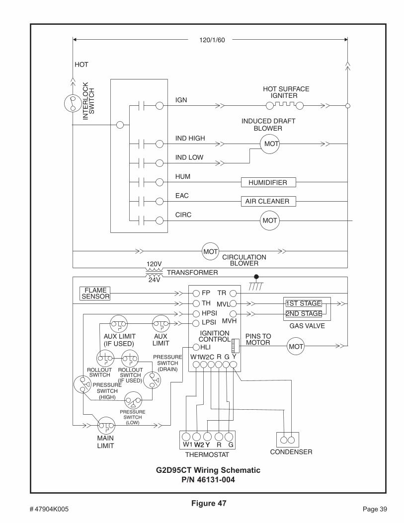
# 47904K005 Page 39Figure 47
G2D95CT Wiring SchematicP/N 46131-004