Embed Size (px)
Citation preview
EcoDWT plus 3
Installation InstructionsFor Lubricating and Hydraulic Oil Storage and Dispensing
Listed under UL Standard SU2258
Meets the requirements of ANSI/NFPA 31ANSI/NFPA 30
NFPA 30aCSA B-139-04
Roth IndustriesPO Box 245
Syracuse, New York 13211Toll Free: 888-266-7684
Fax: 315-475-0200Email: [email protected]
www.rothlubetanks.com
Roth DWT Installation Manual 2 Lubricating & Hydraulic Oil Storage and Dispensing11.14
Table of ContentsSection 1 - The Roth Industries EcoDWT plus 3 Double Wall Tank
Construction Models and Specifications Third Party Testing and Approvals Installation Training Warranty Terms and Product Registration
Section 2 - Installation Parts And Accessories
Parts Supplied with Tank Dispensing System Installation Accessories
Section 3 - Pre-Installation
Permits and ApprovalsWarnings and Cautions Tank Unpacking and Inspection
Section 4 - General Installation Instructions
Site Selection Locating the TankTank Base Installation Flood and Earthquake Considerations Tie Down Kit Piping ConnectionsNormal and Emergency VentingTesting and Inspection
Section 5 - Hose Reel Bracket and Hose Reel Instalation
2” Metal AdaptorHose Reel Bracket Assembly Hose Reel
Section 6 - Completed Installation Review and Warranty Documentation
Section 7 - Yearly Maintenance and Troubleshooting
Yearly MaintenanceTroubleshooting
Fill Chart
Page 3
Page 3Page 4Page 5Page 5Page 6
Page 7
Page 7Page 8
Page 9
Page 9Page 9Page 10 Page 11
Page 11Page 12Page 12Page 13Page 13Page 14Page 15Page 16
Page 17
Page 17Page 17Page 20
Page 21
Page 22
Page 22Page 23
Page 25
Roth DWT Installation Manual 3 Lubricating & Hydraulic Oil Storage and Dispensing11.14
Section 1 - The Roth Industries EcoDWT plus 3 Double Wall Tank
Construction
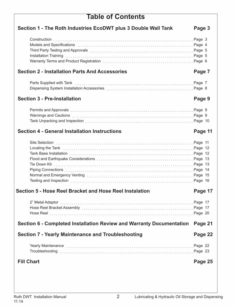
1. The Roth EcoDWT plus 3 storage tank is a double wall tank (DWT) providing both primary and secondary containment tanks for #2 fuel oil, diesel fuel, bio-fuels up to B20, and both new and used automotive motor oils. It is engineered to be the finest fuel storage tank available for residential and light commercial use and one that will provide decades of trouble free service.
2. As the name indicates, it is the ecologically sound choice for fuel oil storage, additionally providing three distinct advantages ( the “plus 3”) over common single wall tanks: superior fire protection over most single wall tanks by keeping the oil cooler and therefore less stress on the tank seams, as shown in UL fire tests; the combination of a steel tank encasing a plastic tank protects the fuel oil products, particularly bio-fuels, with the best light and diffusion barrier; when properly secured in place, the double wall tank provides excellent safe fuel oil storage in flood prone locations, a record established in over forty years of use.
3. The primary containment tank is made of high density polyethylene resin and is formed by a rigorously controlled blow molding process. Polyethylene is a material that combines flexibility with very high resistance to the corrosive effects of both acids and water. Acids are found in all fuel oil products and are, in combination with water, the primary cause of steel tank failure. Water is commonly found in fuel oil storage tanks from water vapor, introduced by the vent piping primarily during the emptying of the tank, condensing inside the tank as the air cools when in contact with the cooler oil. The use of polyethylene, with its high resistance to corrosion, essentially eliminates the foremost reason for failure.
Roth DWT Installation Manual 4 Lubricating & Hydraulic Oil Storage and Dispensing11.14
4. The secondary containment tank is made with 19 gauge galvanized steel. The use of steel offers strength to resist damage to the inner tank from impacts by other objects, rigidity to support the flexible inner tank, and the ability for electrical grounding of the tank where required by local code. The outer tank sides and bottom are formed from one sheet of steel, which is then shaped to receive the panels used at each end of the tank. The seams are caulked and then rolled in a three step robotic procedure, producing a strong, fluid tight and weld-free joint.
5. Each inner and outer tank is tested for defects and liquid tightness. The inner tank is pressure tested to 4.35psi. It is also weighed to make sure it contains the correct amount of material, and finally measured ultrasonically at critical points to verify that it has the required wall thickness. Each sheet of steel for the outer tank is inspected for damage or blemishes that could compromise the galvanized coating. Once the outer tank is assembled, it is pressure tested to .25 - .30psi to ensure the integrity of its seams. The inner tank is then placed inside the outer tank, gaskets placed around the four openings of the inner tank, and the outer tank top installed, riveted into place, and its edge rolled. The leak detector, #3 gaskets, plastic and die-cast metal adaptors, cap nuts and dust plugs are then installed, labels affixed, the warranty packet and tank base placed on top of the tank, and finally a protective plastic shrink wrap is put over the top of the completed tank.
6. The completed tank has four connections at the top and, unlike a standard steel tank and most other poly tanks, none elsewhere. By eliminating a connection below the oil level in the tank, a potential source of leakage is eliminated. The four connections can be used interchangeably, providing the installer with greater flexibility in accommodating difficult or unusual piping installations.
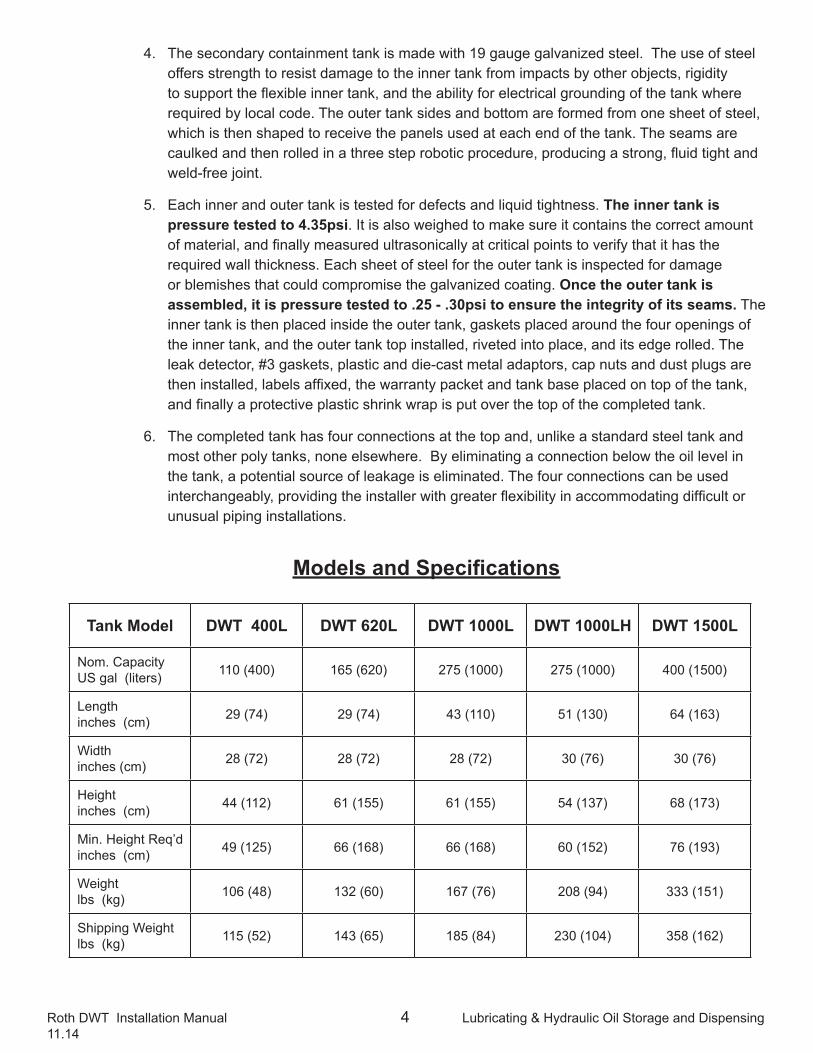
Models and Specifications
Tank Model DWT 400L DWT 620L DWT 1000L DWT 1000LH DWT 1500L
Nom. Capacity US gal (liters) 110 (400) 165 (620) 275 (1000) 275 (1000) 400 (1500)
Length inches (cm) 29 (74) 29 (74) 43 (110) 51 (130) 64 (163)
Width inches (cm) 28 (72) 28 (72) 28 (72) 30 (76) 30 (76)
Height inches (cm) 44 (112) 61 (155) 61 (155) 54 (137) 68 (173)
Min. Height Req’d inches (cm) 49 (125) 66 (168) 66 (168) 60 (152) 76 (193)
Weight lbs (kg) 106 (48) 132 (60) 167 (76) 208 (94) 333 (151)
Shipping Weight lbs (kg) 115 (52) 143 (65) 185 (84) 230 (104) 358 (162)
Roth DWT Installation Manual 5 Lubricating & Hydraulic Oil Storage and Dispensing11.14
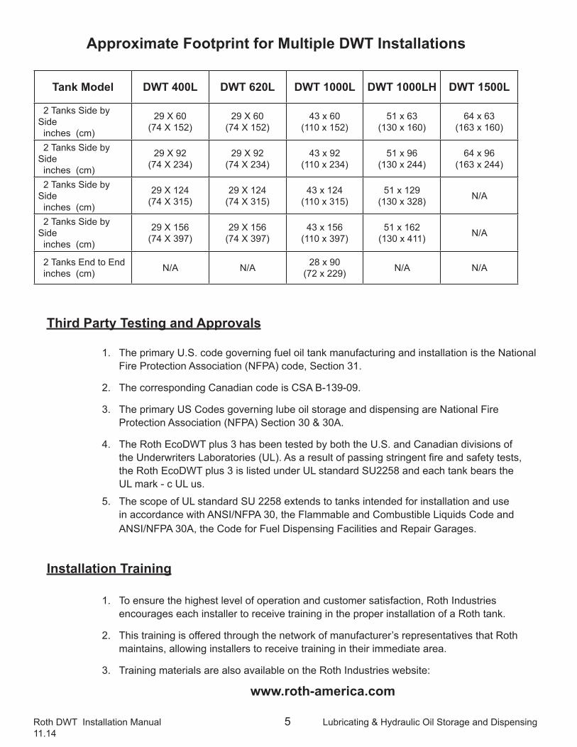
Approximate Footprint for Multiple DWT Installations
Tank Model DWT 400L DWT 620L DWT 1000L DWT 1000LH DWT 1500L
2 Tanks Side by Side inches (cm)
29 X 60(74 X 152)
29 X 60(74 X 152)
43 x 60(110 x 152)
51 x 63(130 x 160)
64 x 63(163 x 160)
2 Tanks Side by Side inches (cm)
29 X 92(74 X 234)
29 X 92(74 X 234)
43 x 92(110 x 234)
51 x 96(130 x 244)
64 x 96(163 x 244)
2 Tanks Side by Side inches (cm)
29 X 124(74 X 315)
29 X 124(74 X 315)
43 x 124(110 x 315)
51 x 129(130 x 328) N/A
2 Tanks Side by Side inches (cm)
29 X 156(74 X 397)
29 X 156(74 X 397)
43 x 156(110 x 397)
51 x 162(130 x 411) N/A
2 Tanks End to End inches (cm) N/A N/A 28 x 90
(72 x 229) N/A N/A
Third Party Testing and Approvals
1. The primary U.S. code governing fuel oil tank manufacturing and installation is the National Fire Protection Association (NFPA) code, Section 31.
2. The corresponding Canadian code is CSA B-139-09.
3. The primary US Codes governing lube oil storage and dispensing are National Fire Protection Association (NFPA) Section 30 & 30A.
4. The Roth EcoDWT plus 3 has been tested by both the U.S. and Canadian divisions of the Underwriters Laboratories (UL). As a result of passing stringent fire and safety tests, the Roth EcoDWT plus 3 is listed under UL standard SU2258 and each tank bears the UL mark - c UL us.
5. The scope of UL standard SU 2258 extends to tanks intended for installation and use in accordance with ANSI/NFPA 30, the Flammable and Combustible Liquids Code and ANSI/NFPA 30A, the Code for Fuel Dispensing Facilities and Repair Garages.
Installation Training
1. To ensure the highest level of operation and customer satisfaction, Roth Industries encourages each installer to receive training in the proper installation of a Roth tank.
2. This training is offered through the network of manufacturer’s representatives that Roth maintains, allowing installers to receive training in their immediate area.
3. Training materials are also available on the Roth Industries website:
www.roth-america.com
Roth DWT Installation Manual 6 Lubricating & Hydraulic Oil Storage and Dispensing11.14
Warranty Terms and Product Registration
1. Under the terms of the warranty, Roth Industries warrants the Product against leakages caused by defects in materials and workmanship for a period of thirty (30) years from the “Start Date”.
2. During the first ten (10) years of the warranty period, Roth shall (i) at its discretion, either repair the Product or provide a replacement product of similar size, design and quality, and (ii) pay all labor costs associated with such repair and/or replacement, all of which shall be at Roth’s expense up to a maximum of one thousand ($1,000) USD in each case. Purchaser shall be responsible for payment of the costs of shipping, freight and insurance on any replacement product, all of which shall be at Purchaser’s expense.
3. In addition, during this first ten (10) year period ONLY, in the event that all conditions contained in the Limited Warranty are otherwise satisfied, Roth shall also reimburse purchaser, up to a maximum amount of US $2 million, for the costs and expenses incurred by Purchaser for damage to purchaser’s property directly and proximately caused by a leakage of oil from a defective Product.
4. During years eleven (11) through year thirty (30) of the warranty period, Roth shall, at its discretion, either repair the Product or provide a replacement product (or 100% credit towards the purchase price of a replacement product) of similar size, design and quality. Purchaser shall be responsible for payment of all labor costs associated with such repair and/or replacement, as well as the costs of shipping, freight and insurance on any replacement product, all of which shall be at Purchaser’s expense.
5. The warranty period (“Start Date”) begins at the date of installation of the Product as recorded on the warranty card and submitted to Roth after installation. If the warranty card is not submitted, the warranty period (“Start Date”) begins at the date of manufacture of the Product. THIS LIMITED WARRANTY SHALL BE VOID IF THE PRODUCT IS NOT INSTALLED WITHIN TWELVE (12) MONTHS AFTER THE DATE OF SALE BY THE PURCHASER (DISTRIBUTOR) TO THE INSTALLER.
6. Though statements above are a part of the warranty statement, they do not reflect all warranty conditions. Please read the limited warranty certificate to be informed of all conditions and rights.
Roth DWT Installation Manual 7 Lubricating & Hydraulic Oil Storage and Dispensing11.14
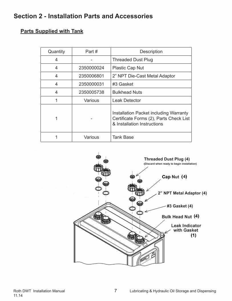
Section 2 - Installation Parts and Accessories
Parts Supplied with Tank
Quantity Part # Description
4 - Threaded Dust Plug
4 2350000024 Plastic Cap Nut
4 2350006801 2” NPT Die-Cast Metal Adaptor
4 2350000031 #3 Gasket
4 2350005738 Bulkhead Nuts
1 Various Leak Detector
1 -Installation Packet including Warranty Certificate Forms (2), Parts Check List & Installation Instructions
1 Various Tank Base
Threaded Dust Plug (4)(Discard when ready to begin installation)
#3 Gasket (4)
2” NPT Metal Adaptor (4)
Roth DWT Installation Manual 8 Lubricating & Hydraulic Oil Storage and Dispensing11.14
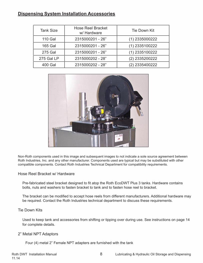
Dispensing System Installation Accessories
Non-Roth components used in this image and subsequent images to not indicate a sole source agreement between Roth Industries, Inc. and any other manufacturer. Components used are typical but may be substituted with other compatible components. Contact Roth Industries Technical Department for compatibility requirements.
Hose Reel Bracket w/ Hardware
Pre-fabricated steel bracket designed to fit atop the Roth EcoDWT Plus 3 tanks. Hardware contains bolts, nuts and washers to fasten bracket to tank and to fasten hose reel to bracket.
The bracket can be modified to accept hose reels from different manufacturers. Additional hardware may be required. Contact the Roth Industries technical department to discuss these requirements.
Tie Down Kits
Used to keep tank and accessories from shifting or tipping over during use. See instructions on page 14 for complete details.
2” Metal NPT Adaptors
Four (4) metal 2” Female NPT adapters are furnished with the tank
Tank Size Hose Reel Bracketw/ Hardware Tie Down Kit
110 Gal 2315000201 - 26” (1) 2335000222
165 Gal 2315000201 - 26” (1) 2335100222275 Gal 2315000201 - 26” (1) 2335100222
275 Gal LP 2315000202 - 28” (2) 2335200222400 Gal 2315000202 - 28” (2) 2335400222
Roth DWT Installation Manual 9 Lubricating & Hydraulic Oil Storage and Dispensing11.14
Section 3 - Pre-Installation
It is very important to read and familiarize yourself with these instructions before installing the tank(s). There are a number of steps that are crucial to a successful installation and to maintaining the warranty.
Permits and Approvals
Installing a single Roth EcoDWT plus 3 inside a building is a straightforward process. Nearly all municipalities have codes governing the installation and use of oil tanks. Always consult with the code officers and inspectors before installing a Roth EcoDWT plus 3 to be sure you are in compliance with all applicable local codes and have obtained all required permits. Code officers may be unfamiliar with the Roth double wall tank, so time taken in acquainting the officer(s) with the tank’s unique advantages and certifications will usually make final approval much easier.
Warnings and Cautions
To the Wholesaler:
1. Fully inspect the tank for shipping damage. The tanks are inspected for damage before shipment from the manufacturing facility and must be inspected for shipping damage upon delivery. If damage is found, the shipping company, not Roth Industries, must be notified.
2. Do not remove shrink wrap covering unless it will be replaced with similar material.
3. Do not store tanks outside without shrink wrap covering to prevent water seepage into the interstitial space between the two tanks and to prevent the destruction or loss of the supplied warranty materials.
4. Tanks should not be stored outside or uncovered for more than thirty (30) days to prevent UV degradation of plastic materials
5. Confirm that the warranty package is with the tank. It is located on top of the tank under the shrink wrap and easily visible. If it is missing contact Roth for a replacement package.
To the Installer:1. Do not remove the shrink wrap until the tank has either been moved inside or is ready to
have the cover placed on it if an outside installation.
2. Failure to follow the instructions given in this installation manual may:
a. Void the tank warranty. b. Compromise the structural integrity of the tank, requiring its replacement. c. Result in personal injury and/or property damage. d. Make the installer liable to penalties under applicable state and local law.
4. Do not install without obtaining appropriate permits and approvals.
Roth DWT Installation Manual 10 Lubricating & Hydraulic Oil Storage and Dispensing11.14
5. Always install the Roth tank according to applicable building and health codes for oil storage systems.
6. Do not install equipment greater than 10 lbs. (4.5 kg.) directly on the tank connections without external support
Tank Unpacking and Inspection
1. The top and upper portions of the Roth EcoDWT plus 3 are covered with shrink wrap plastic designed to keep the top of the tank weathertight. The shrink wrap must be left in place until the tank has been moved inside or is ready to have the cover placed on it if an outside installation. It is transparent, so the tank top and connections can be examined for damage. The base for each tank is shipped on top of the tank to protect the fittings during shipping.
2. The tanks are inspected for damage before shipment from the manufacturing facility and must be inspected for shipping damage upon delivery. If damage is found, the wholesaler or shipper, not Roth Industries, must be notified.
3. In the course of shipping and handling after the tanks leave the Roth warehouse, some minor denting and scraping of the tanks may occur. Minor scratches and scrapes on the surface of the galvanized steel outer tank can be easily repaired by cleaning the surface with any common degreaser and then coating the affected area with any zinc bearing paint designed for such repairs. Most hardware and building supply stores will carry one or more brands of galvanizing repair products.
4. Dents of a ¼ inch depth or less above the curved portions of the sides or in the end panels are generally considered minor and will not affect the integrity of the tank. If the deepest part of the dent forms a sharp projection against the inner tank, or if the dent is on or below the curved sides, this can abrade the surface of the inner tank over time and weaken it. A tank damaged in this way should not be used.
5. If the rolled seam has been struck and is distorted to the left or right ¼ inch or less, the sealing compound will still be intact. Any seam distorted more than ¼ inch or directly dented in will have the sealing compound compromised and should not be used. Any tank installed with unacceptable dents will not be covered by the warranty.
Contact the Roth Industries Technical Department if you have any questions concerning dents or scraping on the units. Typically, you will be asked to send pictures of the tank.
Roth DWT Installation Manual 11 Lubricating & Hydraulic Oil Storage and Dispensing11.14
Section 4 - General Installation InstructionsSite Selection
The Roth EcoDWT plus 3 must be installed indoors for this application.
The following standards must be met:
(Always check local building and fire codes for specific requirements in your location.)
1. Level surface - The Roth EcoDWT plus 3 is an upright tank having a higher center of gravity than a standard single wall tank. This design allows a smaller footprint than a typical single wall tank. The result is also a taller tank profile, requiring the tank to be installed so that it is plumb to within a ½ inch of vertical, as checked on both an end and a side. If the tank is not plumb the proper alignment of piping connections will prove difficult, especially with the use of expansion kits for multiple tank setups. The accuracy of the fuel gauge and the correct operation of the vent whistle will also be affected. If the tank is more than ½ inch out of plumb, the surface must be leveled with an appropriate leveling compound or the product warranty is void.
2. Weight bearing capacity - Since #2 fuel oil weighs 7.2 lbs/gallon, a model 1000L (275 gal.) tank will hold approximately 1730 lbs when full, which brings the total weight of the tank to about 1900 lbs or just short of a ton. Since the model 1000L has a footprint of 8.3 ft2, this means the load bearing surface is carrying about 227 lbs/ft2. NFPA 31-7.3 and CSA B-139-09: 7.3.8 have specific requirements for oil tank foundations that must be followed. The base for the Roth DWT requires full contact support under each of the tubular legs to produce a properly stable installation. Use of masonry blocks such as pavers, sidewalk blocks, and cement wall blocks will not provide sufficient support and will void the warranty.
3. Minimum clearance - A minimum of 2 inches of clearance is needed between the Roth EcoDWT plus 3 and any wall, post, or other permanently installed structural member, support, or barrier. When the tank is filled with oil, its sides could expand horizontally as much as 2 inches, so the clearance is required to prevent contact between, and undue pressure being applied to, either the tank side or the structure next to it. This distance also allows for inspection of the tank sides. CSA B139-09: 7.3.5 states that a minimum clearance of 460 mm (18 in) be made along one side and one end for service accessability. The tank dimensional tables give the minimum height needed for installation, but it is recommended that there be a minimum clearance over a tank of 2 feet to permit removal and reinstallation of the single use leak detector, if necessary.
4. Proper drainage - Although the Roth EcoDWT plus 3 outer tank and base are made from galvanized steel with a minimum expected life span of 30 years with normal use, prolonged exposure to water and water-borne salts and/or acids can significantly reduce that life span. It is very important that the tank installation site has good drainage, and that the surface the tank rests on is dry for the majority of the time. Any water from wash areas or water softener units must be directed away from where the tank is located.
Roth DWT Installation Manual 12 Lubricating & Hydraulic Oil Storage and Dispensing11.14
5. Locating the Tank
1. Make sure the tank will fit through all doors, stairs, halls, and turns taken to reach its intended placement. The tank cannot be dismantled or otherwise altered to make it fit through smaller spaces and any attempt to do so will destroy its structural integrity as well as void the warranty.
2. Examine the desired tank location for deficiencies in the load bearing surface, such as irregularities, slope, and dampness. If a level pad will be poured on the existing floor, it should extend 6 inches past all exposed sides of the tank.
3. The tank must not be installed closer than 5 feet to the heating appliance (NFPA 31 – 7.5.6) and cannot obstruct access to other utilities’ panels, meters, or control valves.
4. Because the connection points of the inner polyethylene tank project above the outer tank top, the DWT must not be installed near a window that will allow exposure to sunlight (UV radiation) on these connections. Although the polyethylene does have limited UV inhibitors in it, prolonged exposure to sunlight can start breaking down the exposed plastic. The same precaution applies to the clear plastic cover on the leak detector.
5. After the site is prepared, remove shrink wrap and other packing materials and thoroughly inspect the tank and accessories for any hidden damage or missing parts. If damaged, contact the wholesaler the tank was purchased from for resolution.
6. Once the inspection is complete, the installation can begin. Each tank has 4 connection ports on the top. These can be used interchangeably during installation for the various tank fittings, providing maximum flexibility for the planned connections.
The certification label on the tank should be visible after installation.
Tank Base Installation
1. The Roth EcoDWT plus 3 uses a one piece base assembly, known as a cradle base, for support. This base is shipped on top of the tank to provide protection for the fitting connections and is held in place by the shrink wrap plastic.
2. The base consists of two or more steel tubular “legs” running horizontally the full width of the tank with the cradle assembly attached to them. The design of the base requires the legs to be in contact with the floor for their entire length, or distortion and possible failure of the base can occur.
3. Once the site is ready for the tank to be set in place, simply set the base on the floor in the approximate location the tank will be installed and place the tank on the base. There is no need to connect the base to the tank, as it is designed to lock in place when the tank is filled with oil. Once the tank is on the base, the unit can be easily slid to its permanent location, allowing for proper clearances.
Failure to use the base may result in tank failure and will void the warranty.
Roth DWT Installation Manual 13 Lubricating & Hydraulic Oil Storage and Dispensing11.14
Flood and Earthquake Considerations
1. Always consult local codes and regulations regarding above ground oil storage tank installations in earthquake or flood prone areas. For seismic rated anchoring requirements contact the Roth Technical Department
2. In areas where a threat of flooding or high winds exists, or in basements with a history of flooding, use of the Roth tie-down kits is recommended.
Tie Down Kit
Tie Down Kits are required with Hose Reel Application
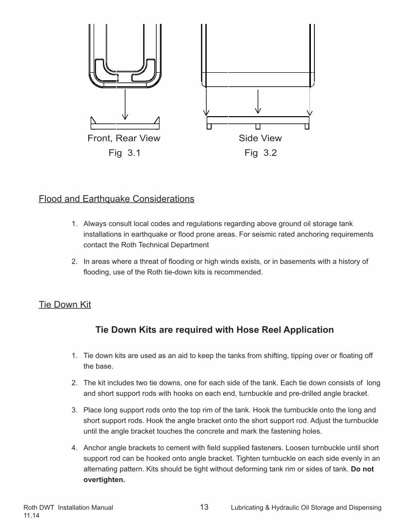
1. Tie down kits are used as an aid to keep the tanks from shifting, tipping over or floating off the base.
2. The kit includes two tie downs, one for each side of the tank. Each tie down consists of long and short support rods with hooks on each end, turnbuckle and pre-drilled angle bracket.
3. Place long support rods onto the top rim of the tank. Hook the turnbuckle onto the long and short support rods. Hook the angle bracket onto the short support rod. Adjust the turnbuckle until the angle bracket touches the concrete and mark the fastening holes.
4. Anchor angle brackets to cement with field supplied fasteners. Loosen turnbuckle until short support rod can be hooked onto angle bracket. Tighten turnbuckle on each side evenly in an alternating pattern. Kits should be tight without deforming tank rim or sides of tank. Do not overtighten.
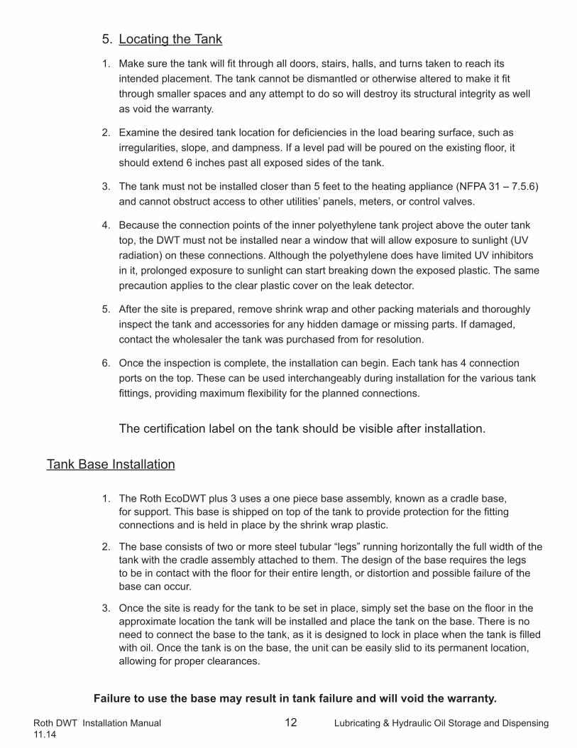
Front, Rear View Side ViewFig 3.1 Fig 3.2
Roth DWT Installation Manual 14 Lubricating & Hydraulic Oil Storage and Dispensing11.14
5. Be sure tank remains level during and after tightening the tie down kits.
6. Tie down kits may not be effective if the tank is less than half full and a flooding event occurs. In areas with a risk of flooding, please contact Roth Industries Technical Department to determine best method for securing tank.
7. Use one kit for 400L, 620L, &1000L tanks Use two kits for 1000LH & 1500L tanks.
8. Additional kits maybe used to increase stability or where conditions or code require it.
Piping Connections
1. All connections to the Roth EcoDWT plus 3 use a flat rubber #3 gasket to seal against the tank opening and to ensure the connection is odor free. The various fittings are secured to the tank with a large black plastic cap nut. Once installed, 18 ft-lb of torque applied to the cap nut seals the connection; hand tightening is the acceptable equivalent of this. The connections to the tank are designed to seal against atmospheric pressure only and not the higher fluid or pumping pressures. It can not be considered an oil tight connection. In the event the tank is overfilled, the connection may allow oil to seep onto the top of the tank.
2. Do not use pipe sealants or PTFE tape on any threaded plastic connections, as these products can cause the plastic to degrade. These sealants can be used on metal to metal connections.
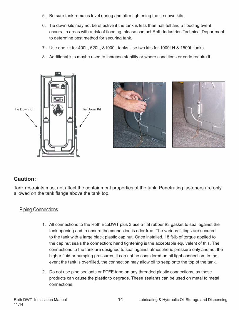
Tie Down Kit Tie Down Kit
Caution: Tank restraints must not affect the containment properties of the tank. Penetrating fasteners are only allowed on the tank flange above the tank top.
Roth DWT Installation Manual 15 Lubricating & Hydraulic Oil Storage and Dispensing11.14
Normal and Emergency Venting
All atmospheric storage vessels require venting to prevent:
• Tank pressure accumulation while filling with liquid• Tank vacuum accumulation while emptying tank
Normal Venting
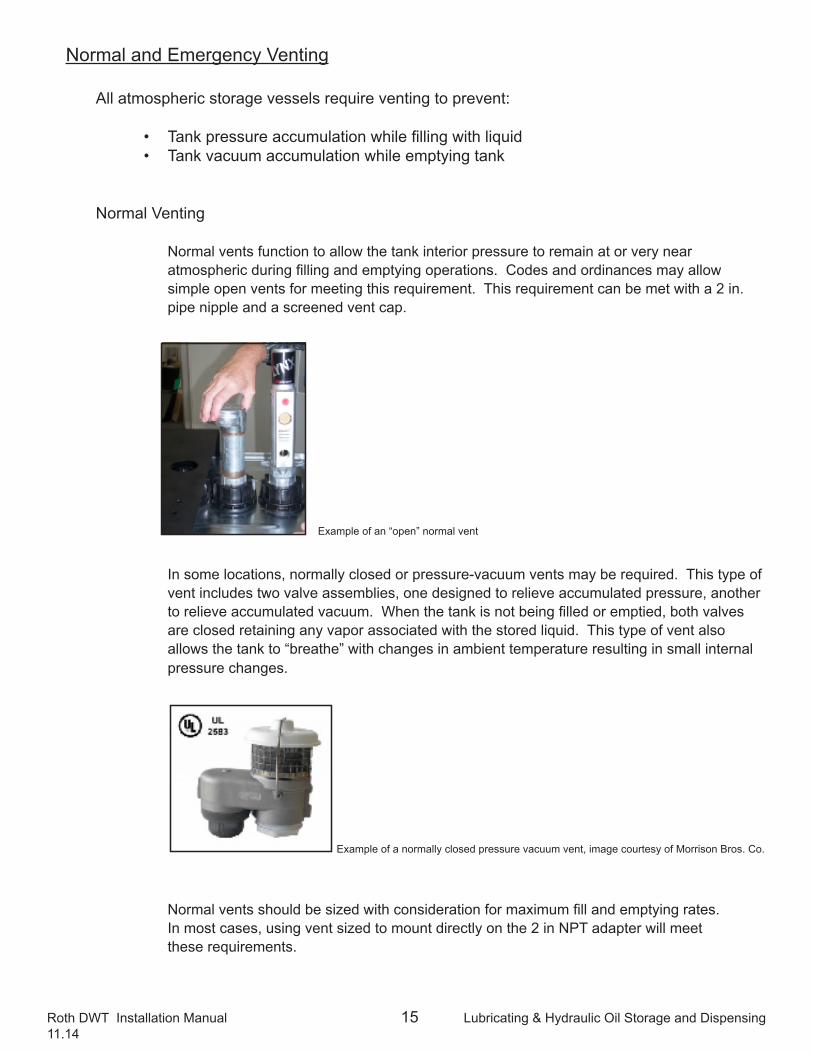
Normal vents function to allow the tank interior pressure to remain at or very near atmospheric during filling and emptying operations. Codes and ordinances may allow simple open vents for meeting this requirement. This requirement can be met with a 2 in. pipe nipple and a screened vent cap.
In some locations, normally closed or pressure-vacuum vents may be required. This type of vent includes two valve assemblies, one designed to relieve accumulated pressure, another to relieve accumulated vacuum. When the tank is not being filled or emptied, both valves are closed retaining any vapor associated with the stored liquid. This type of vent also allows the tank to “breathe” with changes in ambient temperature resulting in small internal pressure changes.
Normal vents should be sized with consideration for maximum fill and emptying rates. In most cases, using vent sized to mount directly on the 2 in NPT adapter will meet these requirements.
Example of an “open” normal vent
Example of a normally closed pressure vacuum vent, image courtesy of Morrison Bros. Co.
Roth DWT Installation Manual 16 Lubricating & Hydraulic Oil Storage and Dispensing11.14
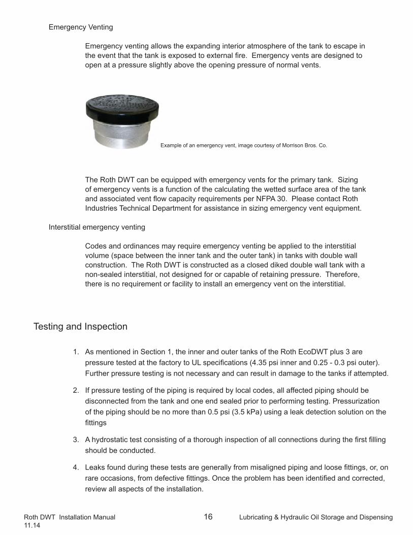
Emergency Venting
Emergency venting allows the expanding interior atmosphere of the tank to escape in the event that the tank is exposed to external fire. Emergency vents are designed to open at a pressure slightly above the opening pressure of normal vents.
The Roth DWT can be equipped with emergency vents for the primary tank. Sizing of emergency vents is a function of the calculating the wetted surface area of the tank and associated vent flow capacity requirements per NFPA 30. Please contact Roth Industries Technical Department for assistance in sizing emergency vent equipment.
Interstitial emergency venting
Codes and ordinances may require emergency venting be applied to the interstitial volume (space between the inner tank and the outer tank) in tanks with double wall construction. The Roth DWT is constructed as a closed diked double wall tank with a non-sealed interstitial, not designed for or capable of retaining pressure. Therefore, there is no requirement or facility to install an emergency vent on the interstitial.
Testing and Inspection
1. As mentioned in Section 1, the inner and outer tanks of the Roth EcoDWT plus 3 are pressure tested at the factory to UL specifications (4.35 psi inner and 0.25 - 0.3 psi outer). Further pressure testing is not necessary and can result in damage to the tanks if attempted.
2. If pressure testing of the piping is required by local codes, all affected piping should be disconnected from the tank and one end sealed prior to performing testing. Pressurization of the piping should be no more than 0.5 psi (3.5 kPa) using a leak detection solution on the fittings
3. A hydrostatic test consisting of a thorough inspection of all connections during the first filling should be conducted.
4. Leaks found during these tests are generally from misaligned piping and loose fittings, or, on rare occasions, from defective fittings. Once the problem has been identified and corrected, review all aspects of the installation.
Example of an emergency vent, image courtesy of Morrison Bros. Co.
Roth DWT Installation Manual 17 Lubricating & Hydraulic Oil Storage and Dispensing11.14
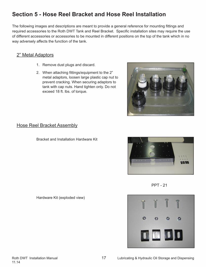
2” Metal Adaptors
1. Remove dust plugs and discard.
2. When attaching fittings/equipment to the 2” metal adaptors, loosen large plastic cap nut to prevent cracking. When securing adaptors to tank with cap nuts. Hand tighten only. Do not exceed 18 ft. lbs. of torque.
Hose Reel Bracket Assembly
Bracket and Installation Hardware Kit
Hardware Kit (exploded view)
The following images and descriptions are meant to provide a general reference for mounting fittings and required accessories to the Roth DWT Tank and Reel Bracket. Specific installation sites may require the use of different accessories or accessories to be mounted in different positions on the top of the tank which in no way adversely affects the function of the tank.
Section 5 - Hose Reel Bracket and Hose Reel Installation
PPT - 21
Roth DWT Installation Manual 18 Lubricating & Hydraulic Oil Storage and Dispensing11.14
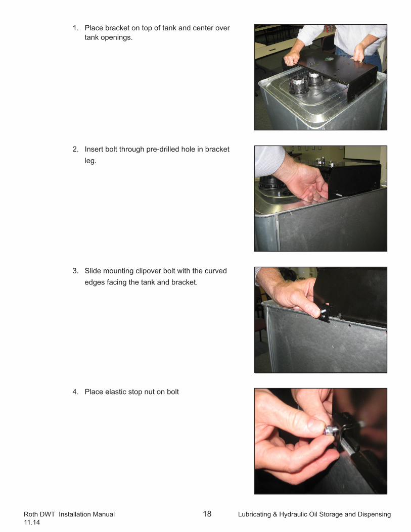
1. Place bracket on top of tank and center over tank openings.
2. Insert bolt through pre-drilled hole in bracket leg.
3. Slide mounting clipover bolt with the curved edges facing the tank and bracket.
4. Place elastic stop nut on bolt
Roth DWT Installation Manual 19 Lubricating & Hydraulic Oil Storage and Dispensing11.14
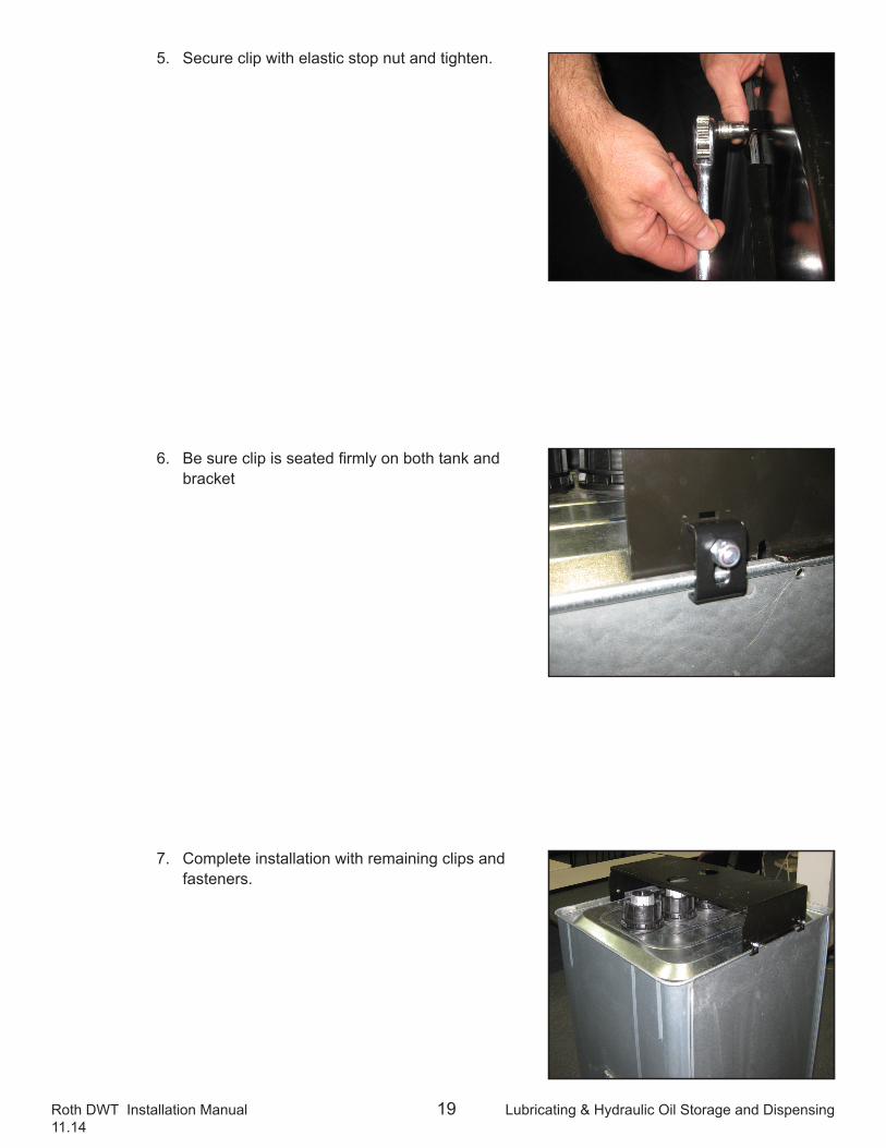
5. Secure clip with elastic stop nut and tighten.
6. Be sure clip is seated firmly on both tank and bracket
7. Complete installation with remaining clips and fasteners.
Roth DWT Installation Manual 20 Lubricating & Hydraulic Oil Storage and Dispensing11.14
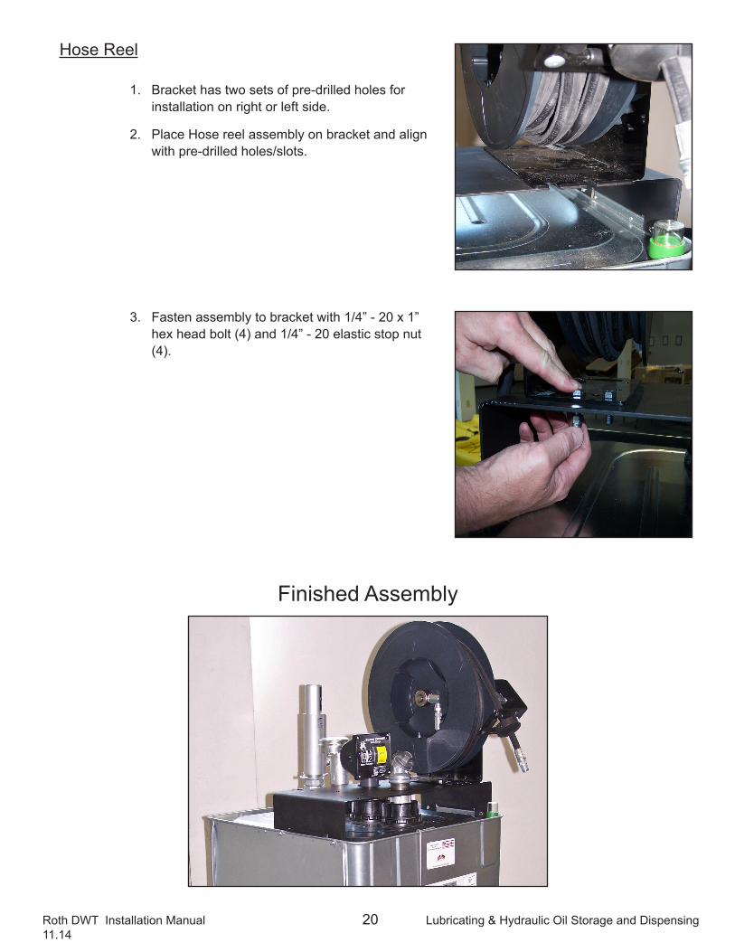
Finished Assembly
Hose Reel
1. Bracket has two sets of pre-drilled holes for installation on right or left side.
2. Place Hose reel assembly on bracket and align with pre-drilled holes/slots.
3. Fasten assembly to bracket with 1/4” - 20 x 1” hex head bolt (4) and 1/4” - 20 elastic stop nut (4).
Roth DWT Installation Manual 21 Lubricating & Hydraulic Oil Storage and Dispensing11.14
Section 6 - Completed Installation Review and Warranty Documentation
1. Once the Roth EcoDWT plus 3 installation is complete, the installer shall review all the work done to verify it is in compliance with the instructions received in training and in this manual, as well as in compliance with applicable local code requirements.
2. Once the review is finished and all requirements are met, the two warranty certificates included with each tank must be completely filled in. One will be returned to Roth Industries at the address found on the certificate and the other will be given to the tank owner for his/her records.
3. Accurate completion of the certificates is extremely important, since this is the only proof that the installation met all warranty requirements.
4. The serial number and date of manufacture are printed on the silver label affixed to each certificate. The date of installation, the name of the tank owner, complete address of the installation, and the installer and/or installation company all need to be provided for the certificate to be valid.
5. Some state, provincial, or local authorities may also require that the installation checklist included in this manual be filled out and submitted as part of the warranty registration process. On both documents the installer’s signature (either individual or company name) is verification that the installation conforms to all Roth instructions and meets the requirements of all applicable codes.
6. Once the completed certificate and installation checklist (if required) are received by Roth, the information is then entered in the database for internal recording keeping and company use only. Roth does not send out notification that the warranty certificate has been received, but owners can call to verify that certificate has been received. This information is for warranty purposes only and will not be shared with any other company for reasons other than warranty maintenance.
7. The warranty is valid on the Roth EcoDWT plus 3 where it is originally installed and therefore remains in effect if ownership of the property is transferred. Any questions concerning the installation or the warranty can be addressed by calling Roth Industries at the telephone numbers listed on the front cover of this manual.
8. The first time the tank is filled, an observer, preferably the installer, should be present to determine that there are no problems that need to be addressed. It is much easier to remedy these problems before the tank is full.
Roth DWT Installation Manual 22 Lubricating & Hydraulic Oil Storage and Dispensing11.14
Section 7 - Yearly Maintenance and Troubleshooting
Yearly maintenance
1. Inspect the site (floor or pad) for any shifting, cracking or unevenness. If any of these conditions exist the integrity of the tank and the installation may be compromised. Steps must be taken to provide a sturdy, level site for the tank.
2. Check that the tank is firmly and squarely set on the base.
3. Inspect all four sides of the tank, the base, and the top for any areas where the galvanized coating has broken down, allowing rust to start. If any spots like this are found, then lightly clean the area with steel wool or fine grit sandpaper, wipe clean, and then coat with any zinc bearing paint intended for galvanized metal.
4. Inspect all the seams in the tank, particularly the seam between the tank body and the top. If there has been excessive pressurization of the tank during filling, the rivets that hold the top in place can be seen pulling into or through the material behind them or in a lifting of the top’s rim to expose the tank body’s edge. If either condition is noted, contact Roth Industries to arrange an inspection of the tank.
5. Check the plastic cap nuts for tightness. They have been found to gradually loosen with the natural expansion and contraction of the tank during filling and emptying, as well as the expansion and contraction of the plastic nuts themselves from the temperature changes. If they are loose turn them until they are hand tight. This will be sufficient to seal the gasket with the appropriate pressure.
6. As pipe joints can loosen over time, inspect all pipe joints for evidence of leakage by fuel oil. If such evidence is found, then contact an oil service technician or plumber to come and retighten the joints.
7. Inspect fill and vent piping for plumbness and that the piping slopes back to tank. Check to see the support brackets are secure and are keeping the weight of the pipes off the tank.
8. Check the top of the tank for any stains that may have occurred from oil seeping onto the top of the tank. If there is oil present on top of the tank, then this must be cleaned up or it will gradually seep into the interstitial space between the two tanks. If the stains are old with no odor, cleanup is optional.
9. Oil stains or oil on top of the tank is usually a sign that the tank was overfilled at some point. The oil company should be notified about this leakage and to verify that the Vent Alarm is working correctly. If it is, then further investigation needs to be done to determine how the overfill occurred and to ensure it isn’t repeated.
By following these procedures, the Roth EcoDWT plus 3 will provide decades of reliable and trouble free oil storage. If in doubt, always call the Roth certified installer or use the numbers in this manual to reach Roth Industries.
Roth DWT Installation Manual 23 Lubricating & Hydraulic Oil Storage and Dispensing11.14
Troubleshooting
1. The red band is showing in the leak detector.
a. Remove the leak detector from the tank by pulling up out of the sealing rubber bushing and observe the amount of fluid (oil or water) visible on the end of the detector tube.
b. If the amount of fluid on the tube is less than a few inches it is nearly always an indication that fluid has seeped into the interstitial from the top of the tank from overfilling the tank.
c. If the amount of fluid on the tube is close to or equal to the amount of oil in the inner tank then it is an indication of a possible leak in the inner tank and the installation needs a closer inspection. Call Roth Industries Inc. to arrange such an inspection.
d. Fluid can removed from the interstitial (space between the two tanks) with a hand pump or with a long rod that has an absorbent material attached to it if the amount is small. The cleanup can be finished by using oil absorbent powder, which will also remove most of the oil smell.
2. Oil smell near the tank
a. If there is the presence of oil of the top of the tank it is an indication of:
1. Leaky pipe joints. Contact an oil service technician or plumber.
2. Plastic cap nuts are loose. Hand tighten or mechanically tighten to 18 ft-lb of torque.
3. Overfill during filling. The oil company should be notified about this leakage and to verify that the Vent Alarm is working correctly.
b. If no oil is visible on the top of the tank then the following must be checked:
1. Plastic cap nuts nay be loose. Hand tighten or mechanically tighten to 18ft-lb of torque.
2. The fill and vent piping is not plumb causing unequal pressure on the o-ring resulting in an air gap on one side of the o-ring. Contact your oil service technician or plumber.
3. Compression fittings on the duplex bushing may be loose.
c. Check the leak detector and following instructions above if red band is showing.
3. Tank sides are bulging and creases have formed on the sides of the tank
a. The sides of the tank may expand up to two (2) inches per side when filled. This is a normal condition.
b. Tank sides bulging more than normal is an indication of one of the following:
Roth DWT Installation Manual 24 Lubricating & Hydraulic Oil Storage and Dispensing11.14
Troubleshooting (cont’d)
1. Too high of a pumping rate during filling. The pumping rate should be 40 - 85 gpm ((150 LPM - 300 LPM) with a maximum line pressure of 85 psi.
2. Restriction in the vent piping. This can be caused by debris in the vent piping and/or vent cap or a problem with the vent whistle. Contact your oil service technician if the vent whistle is causing the problem.
3. The interstitial has water in it and the water has frozen at some point. Call Roth Industries Inc. to arrange an inspection.
Roth DWT Installation Manual 25 Lubricating & Hydraulic Oil Storage and Dispensing11.14
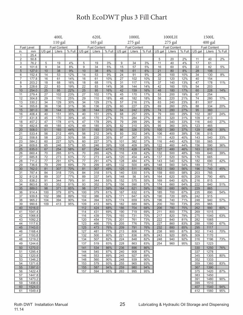
Fuel Level Fuel Content Fuel Content Fuel Content Fuel Content Fuel Contentin. mm US gal Liters % Full US gal Liters % Full US gal Liters % Full US gal Liters % Full US gal Liters % Full1 25.42 50.8 5 20 2% 11 40 2%3 76.2 5 19 4% 5 19 3% 9 34 3% 11 40 4% 17 614 101.6 9 34 8% 9 34 5% 15 57 5% 16 60 6% 22 82 5%5 127.0 10 38 9% 10 38 6% 16 61 6% 21 80 8% 28 1066 152.4 14 53 12% 14 53 9% 24 91 9% 26 100 10% 34 130 8%7 177.8 16 61 14% 16 61 10% 27 102 10% 32 120 12% 40 1548 203.2 18 68 16% 18 68 11% 31 117 11% 37 140 13% 47 178 11%9 228.6 22 83 19% 22 83 14% 38 144 14% 42 160 15% 54 203
10 254.0 25 95 22% 25 95 16% 42 159 16% 48 180 17% 60 228 14%11 279.4 27 102 23% 27 102 17% 45 170 17% 53 200 19% 67 25412 304.8 29 110 25% 29 110 18% 48 182 18% 58 220 21% 74 280 17%13 330.2 34 129 30% 34 129 21% 57 216 21% 63 240 23% 81 30714 355.6 36 136 31% 36 136 22% 60 227 22% 69 260 25% 88 334 20%15 381.0 38 144 33% 38 144 23% 64 242 23% 74 280 27% 95 36016 406.4 40 151 35% 40 151 25% 68 257 25% 79 300 29% 102 387 24%17 431.8 45 170 39% 45 170 27% 75 284 27% 85 320 31% 109 41318 457.2 47 178 41% 47 178 29% 79 299 29% 90 340 33% 116 440 27%19 482.6 49 185 43% 49 185 30% 82 310 30% 95 360 35% 123 46520 508.0 51 193 44% 51 193 31% 86 326 31% 100 380 37% 129 490 30%21 533.4 56 212 49% 56 212 34% 93 352 34% 106 400 39% 136 51522 558.8 58 220 50% 58 220 35% 97 367 35% 111 420 40% 143 540 33%23 584.2 60 227 52% 60 227 37% 101 382 37% 116 440 42% 150 56524 609.6 65 246 57% 65 246 39% 108 409 39% 122 460 44% 156 590 36%25 635.0 67 254 58% 67 254 41% 113 428 41% 127 480 46% 163 61526 660.4 70 265 61% 70 265 42% 116 439 42% 132 500 48% 169 640 39%27 685.8 72 273 63% 72 273 44% 120 454 44% 137 520 50% 176 66528 711.2 77 291 67% 77 291 47% 128 484 47% 143 540 52% 182 690 42%29 736.6 79 299 69% 79 299 48% 132 500 48% 148 560 54% 189 71530 762.0 81 307 70% 81 307 49% 125 511 49% 153 580 56% 196 740 45%31 787.4 84 318 73% 84 318 51% 140 530 51% 159 600 58% 203 76532 812.8 89 337 77% 89 337 54% 148 56 54% 164 620 60% 209 790 48%33 838.2 91 344 79% 91 344 55% 152 575 55% 169 640 62% 216 81534 863.6 93 352 81% 93 352 57% 156 590 57% 174 660 64% 222 840 51%35 889.0 98 371 85% 98 371 59% 164 621 59% 180 680 66% 229 86536 914.4 100 379 87% 100 379 61% 167 632 61% 185 700 67% 235 890 54%37 939.8 102 386 89% 102 386 62% 171 647 62% 190 720 69% 242 91538 965.2 104 394 90% 104 394 63% 174 659 63% 196 740 71% 248 940 57%39 990.6 109 413 95% 109 413 66% 182 689 66% 200 760 73% 255 96540 1016.0 112 424 68% 186 704 68% 206 780 75% 262 990 60%41 1041.4 114 431 69% 190 719 69% 211 800 77% 269 101542 1066.8 116 439 70% 193 731 70% 217 820 79% 275 1040 63%43 1092.2 120 454 73% 201 761 73% 222 840 81% 282 106544 1117.6 123 466 75% 205 776 75% 227 860 83% 288 1090 67%45 1143.0 125 473 76% 209 791 76% 232 880 85% 295 111746 1168.4 127 481 77% 213 806 77% 238 900 87% 302 1143 70%47 1193.8 132 500 80% 221 836 80% 243 920 89% 309 117048 1219.2 134 507 82% 224 848 82% 248 940 92% 316 1196 73%49 1244.6 137 519 83% 228 863 83% 254 960 95% 323 122350 1270.0 141 534 86% 236 896 86% 330 1250 76%51 1295.4 144 545 87% 240 908 87% 337 127852 1320.8 146 553 89% 245 927 89% 345 1305 80%53 1346.2 148 560 90% 248 939 90% 352 133354 1371.6 153 579 93% 255 965 93% 359 1360 83%55 1397.0 155 587 94% 259 980 94% 367 139056 1422.4 157 594 95% 263 995 95% 375 1420 87%57 1447.8 383 145058 1473.2 391 1480 90%59 1498.6 399 151060 1524.0 407 1540 94%61 1549.4 412 1560 95%
Roth EcoDWT plus 3 Fill Chart
400L 620L 1000L 1000LH 1500L 110 gal 165 gal 275 gal 275 gal 400 gal

![TFC KAOHSIUNG FACTORY 30 KMT AMMONIA ... TAAIA[3].pdfT-101 is a flat bed, double wall & double roof anhydrous liquid ammonia storage tank. The internal wall is constructed with low](https://img.pdfslide.net/doc/110x75/5b1a97097f8b9a37258dcb79/tfc-kaohsiung-factory-30-kmt-ammonia-taaia3pdft-101-is-a-flat-bed-double.jpg)