Embed Size (px)
Citation preview

Installation Instructions
BEFORE YOU BEGINRead these instructions completely and carefully.
• IMPORTANT — Save these instructions for local inspector’s use.
• IMPORTANT — Observe all governing codes and ordinances.
• Note to Installer – Be sure to leave these instructions with the Consumer.
• Note to Consumer – Keep these instructions for future reference.
• Product failure due to improper installation is not covered under the Warranty.
WARNING This appliance must be properly grounded.
• ATTENTION INSTALLER — ALL COOKTOPS MUST BE HARD WIRED (DIRECT WIRED) INTO AN APPROVED JUNCTION BOX. A “PLUG AND RECEPTACLE” IS NOT PERMITTED ON THESE PRODUCTS.
• Proper installation is the responsibility of the installer and product failure due to improper installation is NOT covered under warranty.
PARTS INCLUDED
MATERIALS YOU WILL NEED
TOOLS YOU MAY NEED
30 and 36”Electric Cooktop - Induction
CUTTING THE COUNTERTOPIf you are installing the cooktop in a solid surface material such as granite, quartz or any other natural or synthetic solid surface, we recommend that the cutout be prepared by a professional cabinet or countertop installer.Cooktop cutouts in wood or wood-laminate countertops may be able to be prepared using a saber saw and electric drill.
31-2000021 Rev. 2 11-18 GEA
Baffle(For all installations
except over an oven)
2 Hex-Head Screws
Foam TapeWB06K5042
2 Hold Down Brackets
or order alternate installation kit WB01X24570
4 Phillips ScrewsWB01X1137
Saber Saw
Pencil
Safety Glasses
1/8" Drill Bit & Electric or Hand Drill
Ruler or Straightedge
Phillips Head Screwdriver
1/4" Nut Driver
Large Size Wire Nuts
Junction Box (Sized for conduit per local electrical codes.)
90º or Straight Squeeze Connector
for 1” Conduit
Questions? Call us at 1.800.432.2737 or visit GEAppliances.com. In Canada, call 1.800.561.3344 or visit GEAppliances.ca.

2 31-2000021 Rev. 2
Installation InstructionsIMPORTANT SAFETY INSTRUCTIONS
FOR YOUR SAFETY• For Personal Safety, remove house fuse or open
circuit breaker before beginning installation. Failure to do so could result in serious injury or death.
• Be sure your cooktop is installed properly by a qualified installer or service technician.
• To eliminate the risk of burns or fire due to reaching over heated surface elements, cabinet storage located above the surface units should be avoided. If cabinet storage space is to be provided, the risk can be reduced by installing a range hood that projects horizontally a minimum of 5” beyond the bottom of the cabinets. Cabinet installation above the cooktop may be no deeper than 13”.
• Make sure the cabinets and wall coverings around the cooktop can withstand the temperatures (up to 200°F) generated by the cooktop.
• The cooktop should be easy to reach and lighted with natural light during the day.
• Always disconnect the electrical service to the cooktop before repairing or servicing the cooktop. This can be done by disconnecting the fuse or circuit breaker. Failure to do this could result in a dangerous or fatal shock. Know where your main disconnect switch is located. If you do not know, have your electrician show you.
ELECTRICAL REQUIREMENTSThis appliance must be supplied with the proper voltage and frequency, and connected to an individual, properly grounded branch circuit, protected by a circuit breaker or a time delay fuse as noted on name plate and on the chart below.Use the chart below to determine the minimum recommended dedicated circuit protection:
KW Rating240V
KW Rating208V
RecommendedCircuit Size(Dedicated)
20 Amp
4.9 KW–7.2 KW 4.2 KW–6.2 KW 30 Amp
7.3 KW–9.6 KW 6.3 KW–8.3 KW 40 Amp
9.7 KW–12.0 KW 8.4 KW–10.4 KW 50 Amp
We recommend you have the electrical wiring and hookup of your cooktop connected by a qualified electrician. After installation, have the electrician show you where your main cooktop disconnect is located.Wiring must conform to National Electrical Code and all local electrical codes. You can get a copy of the National Electrical Code, ANSI/NFPA No. 70-Latest Edition, by writing to:
National Fire Protection AssociationBatterymarch ParkQuincy, MA 02269
In Canada, wiring must conform to Canadian Electrical Code (CEC).The cooktop conduit wiring is approved for copper wire connection only, and if you have aluminum house wiring, you must use special UL approved connectors for joining copper to aluminum. In Canada, you must use special CSA approved connectors for joining copper to aluminum.You must use a two-wire, three conductor 208/240 VAC, 60 Hertz electrical system. A white (neutral) wire is not needed for this unit. The cooktop must be installed in a circuit that does not exceed 125 VAC nominal to ground.Refer to the name plate on your cooktop for the KW rating for your cooktop. These cooktops require 40 amp service for 30” units, 50 amp service for 36” units.
Name plate location

31-2000021 Rev. 2 3
Installation Instructions
PRE-INSTALLATION CHECKLISTBEFORE YOU BEGINWARNING The electrical power to the cooktop
supply line must be shut off while connections are being made. Failure to do so could result in serious injury or death.A When preparing the cooktop opening, make sure
the inside of the cabinet and the cooktop do not interfere with each other. (See section on preparing the opening.)
B Remove packaging materials and literature package from the cooktop before beginning installation.
C Be sure to place all literature, Owner’s Manual, Installations Instructions, etc. in a safe place for future reference.
D Make sure you have all the tools and materials you need before starting the installation of the cooktop.
E Your home must provide the adequate electrical service needed to safely and properly use your cooktop. (Refer to section on electrical requirements.)
F When installing your cooktop in your home, make sure all local codes and ordinances are followed exactly as stated.
G Make sure the wall coverings, countertop and cabinets around the cooktop can withstand heat (up to 200°F) generated by the cooktop.
H Installing cooktop in combination with other products. Both products must be installed according to their specific product installation instructions. Consideration must be given to the separate electrical requirements and locations:
Over one or two wall ovens: • Only certain models may be installed over
wall ovens. The wall oven and cooktop will both have a label stating which models are approved in combination.
Over a Microwave: • See microwave installation instructions for
how to install a microwave under a cooktop. For vertical dimension of cooktop, see Approximate Cooktop Dimensions section.
In combination with telescopic downdraft vent: • See telescopic downdraft vent instructions for
how to install a vent behind a cooktop. • The countertop must have a deep flat surface
to accommodate the combined installation of the cooktop and vent.
• Allow 12” clearance between the inlet air ports on the bottom of the unit.
Over a warming drawer: • See warming drawer instructions for how to
install a warming drawer under a cooktop. For vertical dimension of cooktop, see Approximate Cooktop Dimensions section.
I Monogram Flush Mount Kit • If you intend to mount your cooktop flush
to the counter, please order kit number JXFLUSH1. The flush mount kit provides supplemental cut-out instructions to mount the product flush with the counter.

4 31-2000021 Rev. 2
Installation InstructionsPREPARING THE OPENING
1 APPROXIMATE COOKTOP DIMENSIONS
3 The following MINIMUM clearance dimensions must be maintained.
If a 30” clearance between the cooking surface and overhead combustible materials or metal cabinets cannot be maintained, a minimum clearance of 24” is required and the underside of the cabinets above the cooktop must be protected with not less than 1/4” insulating millboard covered with sheet metal not less than 30 gage (0.0125”) thick. A ventilation hood may be installed above the cooktop. See the ventilation hood installation instructions for the appropriate dimensions and clearances.
4 Make sure the wall coverings, countertop and cabinets around the cooktop can withstand heat (up to 200°F) generated by the cooktop.
2 CUTOUT DIMENSIONS OF THE COUNTERTOP
To ensure accuracy, it is best to make a template when cutting the opening in the counter.
Size Models X Y Z Front Z Rear*30” PHP9030DJBB
CHP9530SJSS ZHU30RSJSS
29 3/4” 21” 4 5/8” 3 1/4”
30” PHP9030SJSS 29 7/8” 21” 4 5/8” 3 1/4”36” PHP9036DJBB
CHP9536SJSS ZHU36RSJSS
36” 20 1/2” 4 5/8” 3 1/4”
36” PHP9036SJSS 36 1/8” 20 1/2” 4 5/8” 3 1/4”* Depth at rear of cooktop at conduit location.
Cooktop
X
30” models: 19 1/4”36” models: 18 7/8”
Z
Y
30” models: 28 1/16”36” models: 33 3/4”
Use a cabinet base equal to or larger than
the nominal width of the cooktop (30” or 36”).
28 1/2” (30”)33 7/8” (36”)length of cut
1-3/4” MIN. Between rear edge of cutout and the wall behind the cooktop.
19 5/8 (30”)19 1/8” (36”) width of cut
2-1/2” MIN. From front edge of cutout and front edge of countertop.
13" MAX. Depth of
unprotected overhead cabinets
2" MIN. Clearance from cutout to side wall on the left of the unit
15" MIN. Height from countertop to underside of nearest cabinets on both sides of cooktop, including any light rails
2" MIN. Clearance from cutout to nearest vertical wall or cabinet on right side of the unit below the 15” MIN. clearance heightSee label next
to name plate for minimum clearance to
rear wall.
30" MIN. Clearance from countertop to unprotected overhead surface
Wall coverings, cabinets and countertop must withstand heat up to 200°F.
Baffle dimensions
Baffle
Front5”
5 3/16”

31-2000021 Rev. 2 5
Installation Instructions
PREPARING THE OPENING (Cont)
INSTALLING THE COOKTOP
5 VERTICAL CLEARANCESAllow 3” minimum vertical clearance for air space from the cooktop bottom (or 5-7/8” minimum depth from the countertop) to any combustible surfaces, such as the top of a cabinet drawer.
1 INSTALLING THE JUNCTION BOXInstall an approved junction box where it will be easily reached through the front of the cabinet where the cooktop will be located. The cooktop conduit is 4 feet long.
WARNING The junction box must be located where it will allow considerable slack in the conduit for serviceability.
2 PROTECT SURFACE OF COOKTOPPlace a towel or tablecloth onto the countertop. Lay the cooktop upside down onto the protected surface.
3 INSTALL BAFFLESecure the baffle to the cooktop with screws.NOTE: Do not install the baffle when the cooktop is installed over a single oven.
6 FOR AMERICANS WITH DISABILITIES ACT (ADA) FORWARD APPROACH INSTALLATION ONLY
Allow 5” minimum depth between the countertop and an enclosure.NOTE: The enclosure must be made of at least 1/4” wood material. Also, an access panel is required for the junction box, hold-down brackets, and service.
Install junction box so that it can be reached
through the front of the cabinet.
16” Min.
Bottom of Cooktop
Cloth under Cooktop
Hex Head Screws
Rear of Cooktop
DRAWER
3" 5-7/8" 5"

6 31-2000021 Rev. 2
Installation Instructions
INSTALLING THE COOKTOP (Cont)4 ATTACH FOAM TAPE
Apply the foam tape around the outer edge of the glass. Do not overlap the foam tape.
6 INSERT COOKTOP INTO CUTOUTInsert the cooktop centered into the cutout opening. Make sure the front edge of the countertop is parallel to the cooktop. Make final check that all required clearances are met.
Attach Hold Down Brackets to cabinet.
NOTE FOR INSTALLING ABOVE A WALL OVEN: When installing the cooktop above a single wall oven, do not install the baffle. The wall oven will need to be removed during the cooktop installation and then re-installed into its space.IMPORTANT: Maintain a minimum distance of 31-1/4” from the top surface of the countertop to the wall oven platform to ensure that the cooktop and wall oven do not interfere with each other (see picture).
5 MOUNTING PARTSRemove the hold down brackets and screws from the literature package. Screw the Hold Down Bracket to the side of the cooktop unit. Repeat for opposite side of cooktop.
Alternate Installation:You can order an alternate installation kit WB01X24570 with wing nuts and brackets by calling GE Appliances at 800.GE.CARES (800.432.2737). See diagram for instructions.Open the cabinet door. Install the second screw through the bracket and tighten. Then tighten the first screw. Install thumbscrew until it touches the bottom of the countertop.
IMPORTANT: Turn the thumbscrew until it touches the bottom of the countertop. Do not overtighten.
Bottom of Cooktop
Foam Tape
Cooktop Glass
Mounting Screw
Cooktop Countertop
Hold Down Bracket
Cooktop
Hold Down Bracket
Pre-Drilled HoleBottom of Cooktop
Cooktop Glass
Foam Tape
Front of Cooktop
Side of Cooktop
31-1/4” min.(79.4 cm)
SIDE VIEW
Cooktop
Wall Oven
2-1/2” min. (6.4cm)

31-2000021 Rev. 2 7
Installation Instructions
ELECTRICAL CONNECTIONSA When making the wire connections, use the entire
length of conduit provided. The conduit must not be shortened.
B With the cooktop in place, open the front of the cabinet door.
C Insert the wires from the conduit through the opening of the junction box.
The conduit strain relief clamp must be securely attached to the junction box and the flexible conduit must be securely attached to the clamp.
THREE-CONDUCTOR BRANCH CIRCUIT CONNECTIONWhen connecting to a three-conductor branch circuit, if local codes permit:D Connect the
cooktop green ground con duc tor lead to the branch circuit ground (green) using a wire nut.
E Connect the cooktop red lead to the branch circuit red lead in ac cor dance with local codes, using a wire nut.
F Connect the cooktop black lead to the branch circuit black lead in ac cor dance with local codes, using a wire nut. If the residence red, black or white leads are aluminum conductors, see WARNING.
G Install Junction Box Cover.
NEW CONSTRUCTION AND BRANCH CIRCUIT CONNECTION• When installing in new construction, or• When installing in a mobile home, or• When installing in a recreational vehicle, or• When local codes do not permit grounding through
neutral:D Attach the appliance grounding lead (green or
bare copper) in accordance with local codes. If the residence grounding conductor is aluminum, see WARNING.
E Connect the red and black leads from the cooktop conduit to the corresponding leads in the junction box. Connect the ground wire.
F Once the connections are made, secure wires together using wire nuts.
G Install Junction Box Cover.
Ground and Neutral Wires
Junction Box Cover
Ground Wire
Junction Box Cover
Strain Relief
Strain Relief Clamp
Black
Red
Ground
Black
Red
Ground wire location
Strain Relief Clamp
Black
Red
Ground
WARNING Improper connection of alu mi num house wiring to copper leads can result in an electrical hazard or fire. Use only con nec tors designed for joining copper to aluminum and follow the manufacturer’s recom mend ed procedure closely.

8 31-2000021 Rev. 2
Installation Instructions
CHECKLISTS2 OPERATION CHECKLISTA Remove all items from the top of the cooktop
surface.B Turn on the power to the cooktop. (Refer to your
Owner’s Manual.) Verify that all surface burners operate properly.
C Check that the circuit breaker is not tripped nor the house fuse blown.
D Check that conduit is securely connected to the junction box.
NOTE TO ELECTRICIAN:The power leads supplied with this appliance are UL recognized for connections to larger gauge household wiring. The insulation of these leads is rated at temperatures much higher than the temperature rating of household wiring. The current carrying capacity of a conductor is governed by the wire gauge and also the temperature rating of the insulation around the wire.NOTE: ALUMINUM WIRING
• WARNING IMPROPER CONNECTION OF ALUMINUM HOUSE WIRING TO THE COPPER LEADS CAN RESULT IN A SERIOUS PROBLEM.
• Splice copper wires to aluminum wiring using special connectors designed and UL approved for joining copper to aluminum and follow the manufacturer’s recommended connector procedure closely.
NOTE: Wire used, location and enclosure of splices, etc., must conform to good wiring practice and local codes.
1 PRE-TEST CHECKLISTA Remove all protective film, if present, and any
stickers.B Check to be sure that all wiring is secure and
not pinched or in contact with moving parts.C Check level of appliance.D Check that the cooktop is properly grounded.
Instrucciones de instalación
ANTES DE COMENZARLea estas instrucciones por completo y con detenimiento.
• IMPORTANTE — Guarde estas instrucciones para el uso de inspectores locales.
• IMPORTANTE — Cumpla con todos los códigos y ordenanzas vigentes.
• Nota al instalador – Asegúrese de dejar estas instrucciones con el consumidor.
• Nota al consumidor – Conserve estas instrucciones para referencia futura.
• La Garantía no cubre las fallas del producto debido a una instalación incorrecta.
ADVERTENCIA Este artefacto debe tener una correcta conexión a tierra.
• ATENCIÓN INSTALADOR — TODAS LAS ESTUFAS DEBEN CONTAR CON CABLEADO DE CONEXIÓN PERMANENTE (CABLEADO DIRECTO) DENTRO DE UNA CAJA DE CONEXIONES APROBADA. EN ESTOS PRODUCTOS NO SE PERMITE LA CONEXIÓN DEL TIPO “ENCHUFE Y RECEPTÁCULO”.
• La correcta instalación es responsabilidad del instalador y la garantía NO cubre las fallas del producto debido a una instalación incorrecta.
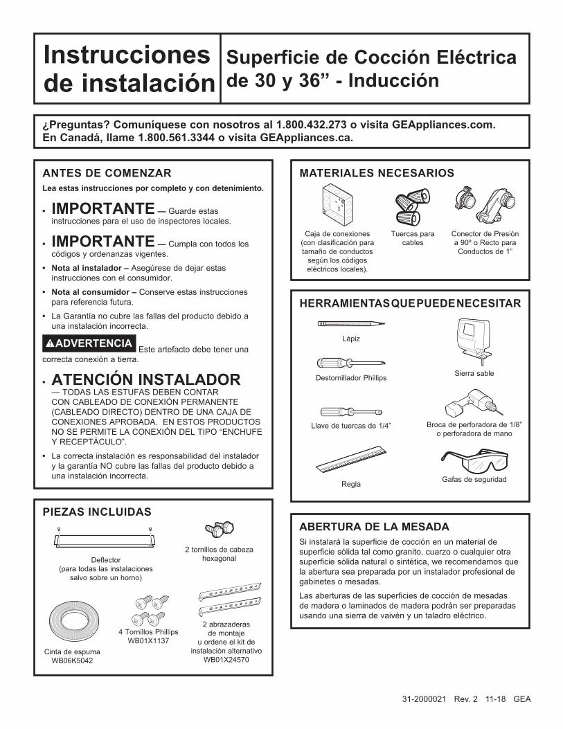
PIEZAS INCLUIDAS
MATERIALES NECESARIOS
HERRAMIENTAS QUE PUEDE NECESITAR
Superficie de Cocción Eléctrica de 30 y 36” - Inducción
ABERTURA DE LA MESADASi instalará la superficie de cocción en un material de superficie sólida tal como granito, cuarzo o cualquier otra superficie sólida natural o sintética, we recomendamos que la abertura sea preparada por un instalador profesional de gabinetes o mesadas.Las aberturas de las superficies de cocción de mesadas de madera o laminados de madera podrán ser preparadas usando una sierra de vaivén y un taladro eléctrico.
31-2000021 Rev. 2 11-18 GEA
Deflector (para todas las instalaciones
salvo sobre un horno)
2 tornillos de cabeza hexagonal
Cinta de espumaWB06K5042
2 abrazaderas de montaje
u ordene el kit de instalación alternativo
WB01X24570
4 Tornillos Phillips WB01X1137
Sierra sable
Lápiz
Gafas de seguridad
Broca de perforadora de 1/8” o perforadora de mano
Regla
Destornillador Phillips
Llave de tuercas de 1/4”
Tuercas para cables
Caja de conexiones (con clasificación para tamaño de conductos
según los códigos eléctricos locales).
Conector de Presión a 90º o Recto para Conductos de 1”
¿Preguntas? Comuníquese con nosotros al 1.800.432.273 o visita GEAppliances.com. En Canadá, llame 1.800.561.3344 o visita GEAppliances.ca.

2 31-2000021 Rev. 2
Instrucciones de instalaciónINSTRUCCIONES DE SEGURIDAD IMPORTANTES
PARA SU SEGURIDAD• Para seguridad personal, quite los fusibles o desconecte
cortacircuitos antes de comenzar la instalación. No hacerlo puede provocar la muerte o una lesión personal grave.
• Verifique que un instalador o un técnico calificados instalen su estufa correctamente.
• A fin de eliminar el riesgo de quemaduras o incendios provocados por inclinarse sobre elementos de superficie calientes, debe evitarse la instalación de gabinetes sobre las unidades de superficie. Si se debe contar con un espacio de gabinetes, puede reducirse el riesgo mediante la instalación de una campana de cocina que sobresalga horizontalmente en 5” como mínimo por la parte inferior de los gabinetes. La instalación de gabinetes por encima de la estufa no debe superar una profundidad de 13”.
• Verifique que los gabinetes y el revestimiento de las paredes ubicadas alrededor de la estufa puedan soportar las temperaturas (hasta 200°F) generadas por el anafe.
• La estufa debe tener un fácil acceso y debe contar con iluminación natural durante el día.
• Siempre desconecte el servicio eléctrico antes de reparar o arreglar la estufa. Esto puede realizarse desconectando los fusibles o el cortacircuitos . No hacerlo puede provocar una descarga peligrosa o fatal. Sepa donde se encuentra el interruptor de desconexión principal. Si no lo sabe, consulte a su electricista.
REQUERIMIENTOS ELÉCTRICOSEste artefacto debe abastecerse con el voltaje y frecuencia adecuados y debe conectarse en un circuito derivado individual con correcta conexión a tierra, protegido por un cortacircuitos o fusible de tiempo retardado, como se señala en la placa de nombre y en el siguiente cuadro.Utilice la tabla de abajo para determinar la protección de circuito dedicado mínima recomendada:
Clasificación de KW 240V
Clasificación de KW 208V
Tamaño de circuito recomendado
(dedicado)
20 Amp
4,9 KW–7,2 KW 4,2 KW–6,2 KW 30 Amp
7,3 KW–9,6 KW 6,3 KW–8,3 KW 40 Amp
9,7 KW–12,0 KW 8,4 KW–10,4 KW 50 Amp
Recomendamos que un electricista calificado conecte el cableado eléctrico y efectúe las conexiones de su estufa anafe. Después de la instalación, solicite al electricista que le muestre donde se encuentra la desconexión principal de la estufa. El cableado debe cumplir con el Código Eléctrico Nacional y con todos los códigos eléctricos locales. Usted puede obtener una copia del Código Eléctrico Nacional ANSI/NFPA No. 70 - última edición escribiendo a:
National Fire Protection AssociationBatterymarch ParkQuincy, MA 02269
El cableado de la estufa está aprobado sólo para conexiones de cables de cobre, y si tiene cableados doméstico de aluminio, usted debe utilizar conectores aprobados por UL para unir cobre con aluminio. Debe utilizarse un sistema eléctrico de 60 hercios, 208/240 VAC de tres conductores y dos hilos. No se necesita un cable blanco (neutral) para esta unidad. La placa de cocción deberá ser instalada en un circuito que no supere los 125 VAC nominales a tierra.Consulte el rótulo sobre su estufa para conocer la clasificación en kilovatios de su estufa.Estas mesadas requieren un servicio de 40 amperes para unidades de 30”, y un servicio de 50 amperes para unidades de 36”.
Ubicación de la placa de nombre

31-2000021 Rev. 2 3
Instrucciones de instalación
LISTA DE CONTROL PRE-INSTALACIÓNANTES DE COMENZARADVERTENCIA La energía eléctrica de la línea
de abastecimiento de la estufa debe estar desconectada mientras se realizan las conexiones. No hacerlo puede provocar la muerte o una lesión personal grave.
A Cuando realice una abertura para la estufa, verifique que la parte interna del gabinete y la estufa no interfieran entre sí. (Ver sección sobre la preparación de la abertura).
B Quite los materiales de embalaje y el paquete con información sobre el producto de la estufa antes de comenzar la instalación.
C Asegúrese de colocar todo el material de información, el Manual de Usuario, las Instrucciones de instalación, etc. en un lugar seguro para referencia futura.
D Asegúrese de contar con todas las herramientas y materiales que necesita antes de comenzar la instalación de la estufa.
E Su hogar debe contar con el servicio eléctrico adecuado necesario para un uso seguro y adecuado de la estufa. (Ver la sección sobre requerimientos eléctricos).
F Cuando instale la estufa en su hogar, asegúrese que todos los códigos y ordenanzas se cumplan al pie de la letra.
G Verifique que el revestimiento de las paredes, la mesada y los gabinetes ubicados alrededor de la estufa puedan soportar el calor (hasta 200°F) generado por la estufa.
H Instalación de la superficie de cocción en combinación con otros productos. Ambos productos deben ser instalados de acuerdo con sus instrucciones de instalación específicas del producto. Se deben tener en consideración los requisitos y ubicaciones eléctricas específicas:
Sobre uno o dos hornos de pared: • Sólo ciertos modelos pueden ser instalados
sobre los hornos de pared. El horno de pared y la superficie de cocción tendrán ambos una etiqueta que indique cuáles modelos están aprobados para uso combinado.
Sobre el Microondas: • Para instalar un microondas debajo de una
superficie de cocción, consulte las instrucciones de instalación del horno microondas. Para conocer la dimensión vertical de la superficie de cocción, consulte la sección de Dimensiones Aproximadas de la Superficie de Cocción.
En combinación con la ventilación telescópica descendente:
• Para instalar una ventilación detrás de la superficie de cocción, consulte las instrucciones de la ventilación telescópica descendente.
• La mesada debe contar con una superficie profunda y plana para ubicar la instalación combinada de la superficie de cocción y la ventilación.
• Deje un espacio de 12” entre los puertos de entrada de aire en la parte inferior de la unidad.
Sobre un cajón para calentar: • Para instalar un cajón para calentar debajo de una
superficie de cocción, consulte las instrucciones de instalación del cajón para calentar. Para conocer la dimensión vertical de la superficie de cocción, consulte la sección de Dimensiones Aproximadas de la Superficie de Cocción
I Kit de Montaje al Ras de Monogram • Si su intención es montar la placa de cocción al ras
de la mesada, ordene el número de kit JXFLUSH1. El kit de montaje al ras provee instrucciones de recorte complementarias para montar el producto al ras de la mesada.

4 31-2000021 Rev. 2
Instrucciones de instalaciónCÓMO PREPARAR LA ABERTURA
1 DIMENSIONES GENERALES DE LA SUPERFICIE DE COCCIÓN
3 Deben mantenerse las siguientes dimensiones MÍNIMAS de espacio libre.
Si no se puede mantener un espacio de 30” entre la superficie de cocción y el material combustible superior o gabinetes de metal, se requiere un espacio libre mínimo de 24”, y el lado inferior de los gabinetes por encima de la estufa debe protegerse con cartón aislante no menor a 1/4” cubierto con planchas metálicas con un grosor no menor a 30 (0.0125”). Podrá ser instalada una campana de ventilación encima de la superficie de cocción. Para conocer las dimensiones y despejes adecuados, consulte las instrucciones de instalación de la campana de ventilación.
4 Verifique que el revestimiento de las paredes, la mesada y los gabinetes ubicados alrededor de la estufa puedan soportar el calor (hasta 200°F) generado por la estufa
2 DIMENSIONES DE LA ABERTURA DE LA MESADA
Para asegurar precisión, es mejor utilizar una plantilla cuando corte la abertura de la mesada.
Estufa
X
30” modelos: 19 1/4”36” modelos: 18 7/8”
Z
Y
30” modelos: 28 1/16”36” modelos: 33 3/4”
Use una base de gabinete igual a o mayor que el
ancho nominal de la placa de cocción (30” o 36”).
28 1/2” (30”)33 7/8” (36”)de ancho de
1-3/4” Mín. entre la abertura cortada y la pared detrás de la estufa
19 5/8 (30”)19 1/8” (36”)
de profundidad e abertura
cortada
2-1/2” Mín. desde el extremo frontal de la abertura cortada y el extremo frontal de la mesada
13" de profundidad
MÁX en gabinetes
aéreos sin protección
2" de espacio libre MÍN desde el corte hasta la pared lateral sobre el lado izquierdo de la unidad
Altura mínima de 15” desde la mesada hasta el lado inferior de los gabinetes más cercanos a ambos lados de la superficie de cocción, incluyendo cualquier riel de luz.
Despeje mínimo de 2” desde la abertura hasta la pared vertical más cercana o el gabinete del lado derecho de la unidad que esté por debajo de una altura de despeje mínimo de 15”.
30" de espacio libre MÍN. desde la mesada hasta la superficie aérea sin protección
El revestimiento de las paredes, los gabinetes y la mesada deben soportar calores de hasta 200°F.
*Profundidad en la parte trasera de la superficie de cocción en la ubicación del conducto.
Para un despeje mínimo en relación a la
pared trasera, lea la etiqueta que está junto a la placa del
nombre.
Dimensiones del deflector
Deflector
Frente5”
5 3/16”
Tamaño Modelos X Y Z FrenteZ Parte Trasera*
30” PHP9030DJBB CHP9530SJSS ZHU30RSJSS
29 3/4” 21” 4 5/8” 3 1/4”
30” PHP9030SJSS 29 7/8” 21” 4 5/8” 3 1/4”36” PHP9036DJBB
CHP9536SJSS ZHU36RSJSS
36” 20 1/2” 4 5/8” 3 1/4”
36” PHP9036SJSS 36 1/8” 20 1/2” 4 5/8” 3 1/4”

31-2000021 Rev. 2 5
Instrucciones de instalación
CÓMO PREPARAR LA ABERTURA (Cont)
CÓMO INSTALAR EL ANAFE
5 ESPACIOS LIBRES VERTICALESDeje un espacio vertical mínimo de 3” para que haya un espacio de aire desde la parte inferior de la superficie de cocción. (o una profundidad mínima de 5-7/8” desde la mesada) hasta cualquier superficie combustible, tal como la parte superior del cajón de un gabinete.
1 INSTALACIÓN DE LA CAJA DE CONEXIONES
Instale una caja de conexiones aprobada en un lugar de fácil acceso a través del frente del gabinete en donde pueda colocarse la estufa. El conducto de la estufa tiene 4 pies de longitud.
ADVERTENCIALa caja de conexiones debe localizarse en donde el conducto esté lo suficientemente flojo para permitir que se le dé servicio.
2 PROTEJA LA SUPERFICIE DEL ANAFEColoque una toalla o mantel sobre la mesada. Apoye la placa de cocción al revés sobre la superficie protegida.
3 INSTALE EL DEFLECTORSujete el deflector la estufa con los tornillos. NOTA: No instale el deflector cuando la estufa está instalado sobre un horno sencillo.
6 INSTALACIÓN POR DELANTE ÚNICAMENTE DE ACUERDO CON LA LEY DE ESTADOUNIDENSES CON INCAPACIDADES (ADA)
Deje un espacio vertical de por lo menos 5” entre la mesada y la cubierta.
NOTA: La cubierta deberá estar hecha de madera de 1/4”. Además, se requiere un panel de acceso para la caja de conexiones , los soportes de los costados, y el servicio técnico.
Instale la caja de conexiones de
modo que pueda alcanzarse a través
del frente del gabinete.
16” Mín.
Parte inferior de la estufa
Paño bajo la estufa
Tornillos con Cabeza Hexagonal
Parte Trasera
de la Placa de Cocción
DRAWER
3" 5-7/8"
CAJÓN
5"

6 31-2000021 Rev. 2
Instrucciones de instalación
CÓMO INSTALAR EL ANAFE (Cont)4 COLOQUE CINTA DE ESPUMA
Aplique la cinta de espuma alrededor de los extremos exteriores del vidrio. No superponga la cinta de espuma.
6 INSERTE LA SUPERFICIE DE COCCIÓN EN EL ENCASTRE
Inserte la estufa centrada en el área cortada. Asegúrese de que el borde frontal del mostrador esté paralelo con respecto a la estufa. Asegúrese de verificar al final que todos los espacios especificados hayan sido respetados.
Adhiera los Soportes al gabinete.
5 PIEZAS MONTABLESSaque las abrazaderas de montaje y tornillos del empaque con material impreso.
Atornille la abrazadera de montaje a un lado de la unidad de la estufa. Repita en el lado opuesto de la estufa.
Instalación Alternativa:Usted puede ordenar un kit de instalación alternativa WB01X24570 con tuercas mariposa y soportes llamando a GE Appliances al 800.GE. CARES (800.432.2737). Para acceder a instrucciones, consulte el diagrama.
Abra la puerta del gabinete. Instale el segundo tornillo a través del soporte y ajuste. Luego ajuste el primer tornillo. Instale el tornillo de mariposa hasta que toque la parte inferior de la mesada.
IMPORTANTE: Gire el tornillo de mariposa hasta que toque la parte inferior de la mesada. No ajuste de más.
Parte inferior del anafe
Cinta de espuma
Vidrio del anafe
Tornillo de montaje
Estufa Mesada
Abrazadera de montaje
Estufa
Soporte
Marca para Realizar Agujero
Parte Inferior de la Superficie de Cocción
Vidrio de la Superficie de Cocción
Adhesivo con Gomaespuma
Frente de la Superficie de Cocción
Lateral de la Superficie de Cocción
NOTA PARA LA INSTALACIÓN SOBRE UN HORNO DE PARED: Al instalar la superficie de cocción sobre un horno de pared simple, no instale el deflector. El horno de pared deberá ser retirado durante la instalación de la superficie de cocción e instalado nuevamente en su espacio.IMPORTANTE: Mantenga una distancia mínima de 31 ¼” desde la superficie superior de la mesada hasta la plataforma del horno de pared, a fin de asegurar que la superficie de cocción y el horno de pared no interfieran uno con el otro (vea la figura).
Mín. de 31 1/4”(79.4 cm)
VISTA LATERAL
Superficie de Cocción
Horno de Pared
Mín. de 2 1/2” (6.4cm)

31-2000021 Rev. 2 7
Instrucciones de instalación
CONEXIONES ELÉCTRICASA Cuando realice las conexiones de cables, utilice toda
la extensión del conducto incluido. El conducto no debe reducirse.
B Con la estufa colocada en su lugar, abra el frente de la puerta del gabinete.
C Inserte los cables del conducto a través de la abertura de la caja de conexiones.
La abrazadera del alivio de tensión del conducto debe estar bien sujeta a la caja de conexiones y el conducto flexible debe estar bien sujeto a la abrazadera.
CONEXIÓN DE CIRCUITO DERIVADO DE TRES CONDUCTORESCuando conecte un circuito derivado de tres conductores, si lo permiten los códigos locales:
D Conecte el cable verde de conductor a tierra de la estufa con la conexión a tierra del circuito derivado (verde) utilizando un tapón de alambre.
E Conecte el cable rojo del anafe con el cable rojo de circuito derivado de acuerdo con códigos locales, utilizando un tapón de alambre.
F Conecte el cable negro del anafe con el cable negro de circuito derivado de acuerdo con códigos locales, utilizando un tapón de alambre. Si los cables rojos, negros o blancos son conductores de aluminio, ver ADVERTENCIA.
G Instale la tapa de la caja de conexiones.
CONEXIÓN DE CONSTRUCCIÓN NUEVA Y DE CIRCUITO DERIVADO• Cuando realice una instalación en una construcción
nueva, o • Cuando realice una instalación en una casa rodante, o• Cuando realice una instalación en un vehículo recreativo, o• Cuando los códigos locales no permiten la conexión a
tierra a través de un cable neutral:
D Conecte el cable a tierra del artefacto (verde o cobre) de acuerdo con los códigos locales. Si el conductor a tierra de la residencia es de aluminio, ver ADVERTENCIA.
E Conecte los cables rojo y negro del conductor de la estufa a los cables correspondientes en la caja de conexiones. Conecte el cable a tierra.
F Una vez que se hayan realizado las conexiones, fije los cables con las tuercas para cables.
G Instale la tapa de la caja de conexiones.
Cables a tierra y neutrales
Tapa de la caja de conexiones
Pinza de alivio de tensión
Negro
Rojo
Descarga a tierra
Pinza de alivio de tensión
Negro
Rojo
Descarga a tierra
Negro
Rojo
Ubicación del cable de
descarga a tierra
Cable a tierra
Tapa de la caja de conexiones
Alivio de tensión
ADVERTENCIA Una conexión inadecuada de cableado doméstico de aluminio con cables de cobre puede generar un peligro eléctrico o un incendio. Sólo use conectores diseñados para unir cobre con aluminio y siga al pie de la letra el procedimiento recomendado del fabricante.

8 31-2000021 Rev. 2
Instrucciones de instalación
LISTAS DE CONTROL2 LISTA DE CONTROL DE
FUNCIONAMIENTOA Retire todos los objetos que se encuentren sobre la
superficie de la estufa.
B Encienda la toma de corriente de la estufa. (Consulte su Manual del propietario). Verifique que todas las hornillas de la superficie funcionen correctamente.
C Verifique que el cortacircuitos no esté desactivado o que se haya fundido el fusible de su hogar.
D Verifique que el conducto esté conectado correctamente a la caja de conexiones.
NOTA AL ELECTRICISTA:Los cables de energía suministrados con este artefacto están reconocidos por UL para conexiones con cableados domésticos de calibres mayores. La aislación de estos cables está clasificada a temperaturas mucho más elevadas que la clasificación del cableado doméstico. La capacidad de transmitir corriente del conductor está determinada por el calibre del cable y también la clasificación de temperatura de la aislación alrededor del cable. NOTA: CABLEADO DE ALUMINIO
• ADVERTENCIA UNA CONEXIÓN INADECUADA DEL CABLEADO DOMÉSTICO DE ALUMINIO CON CABLES DE COBRE PUEDE PROVOCAR UN GRAVE PROBLEMA.
• Empalme cables de cobre con el cableado de aluminio utilizando conectores especiales diseñados y aprobados por UL para unir cobre con aluminio y siga al pie de la letra el procedimiento de conexión recomendado por el fabricante.
NOTA: El cable utilizado, la ubicación y recinto de los empalmes, etc., deben cumplir con una buena práctica de cableado y con los códigos locales.
1 LISTA DE CONTROL PREVIA A LA PRUEBA
A Quite toda la película protectora, si la hubiera, y todos los autoadhesivos.
B Verifique que todo el cableado esté seguro y que no haya sufrido pellizcos o esté en contacto con partes en movimiento.
C Controle el nivel del artefacto.
D Asegúrese que la estufa tenga una conexión a tierra adecuada.