Embed Size (px)
Citation preview

FOR USE WITH WA SERIESWALL MOUNTED AIR CONDITIONERS
SEE TABLE 1 FOR MODEL USAGE
Models:
EHWA3S-B06 EHWA4S-A05EHWA4S-A10 EHWA4S-A15EHWA4S-A20 EHWA5S-A05EHWA5S-A08 EHWA5S-A10EHWA5S-A15 EHWA5S-A20EHWA5S-B06 EHWA5S-B09EHWA5S-B15 EHWA5S-C06EHWA5S-C09 EHWA5S-C15
INSTALLATION INSTRUCTIONSELECTRIC HEAT PACKAGES
Bard Manufacturing Company, Inc.Bryan, Ohio 43506
Since 1914...Moving ahead, just as planned.
Manual: 2100-456Supersedes:File: Volume III, Tab 18Date: 04-29-05

CONTENTS
General InformationNomenclature ................................................... 1Description of Equipment .................................. 1Important ........................................................... 1Shipping Damage ............................................. 1Unpacking Electric Heat Package .................... 1Wiring Main Power ............................................ 3
InstallationInstallation of Heater Package .......................... 5
TablesTable 1 Heater Usage by Model Matrix .......... 2Table 2 Electrical Data .................................... 4Table 3 Terminal and Screw Mounting ............ 7Table 4 Wiring Diagram Usage Matrix .......... 11
FiguresFigure 1 Electrical Connections ...................... 3Figure 2 Installation of Heater Package .......... 6
WA3S, WA4S & WA5S ModelsFigure 3 Rod Support and Screw Mounting .... 7Figure 4A - 4D Terminal Identification ............. 8Figure 5 Wiring Directions ............................... 9
WA3S, WA4S & WA5S ModelsFigure 6 Marking Serial Plate ........................ 10
Wiring Diagrams4097-176 ........................................................ 124097-177 ........................................................ 134097-178 ........................................................ 144097-179 ........................................................ 154097-180 ........................................................ 164097-240 ........................................................ 174097-241 ........................................................ 184097-340 ........................................................ 194097-341 ........................................................ 20

Manual 2100-456Page 1
GENERAL INFORMATION
NOMENCLATURE
EHW A 4S - A 10
DESCRIPTION OF EQUIPMENTThe EHWA series electric heater packages are capableof being field-installed and suitable for use with Bardwall mount air conditioners. The packages consist ofthe electric heat strip, the heater control base whichincludes the heat contactors, and circuit breaker of pulldisconnects, installation instructions and wiringdiagrams. See Table 1 for nominal electrical data andBTU output. Before installation, check unit serial plateto insure the heater package model that you intend toinstall is listed as a heater package that is suitable foruse with the Bard wall mount hi boy unit. See Table 1and Figure 6.
IMPORTANTThe equipment covered in this manual is to be installedby trained, experienced service and installationtechnicians.
SHIPPING DAMAGEUpon receipt of equipment, the carton should bechecked for external signs of shipping damage. Ifdamage is found, the receiving party must contact thelast carrier immediately, preferably in writing,requesting inspection by the carrier�s agent.
UNPACKING ELECTRIC HEAT PACKAGERemove the heat package from the shipping carton. Theheat package must consist of the following:
1. Basic heater.
2. Electric heat control base and wiring.
3. Installation instructions.
4. Wiring diagram (2), one to be applied to unit.
5. Adhesive label to remark serial plate to indicate newmodel number. This is attached to the front of theseinstructions.
ELECTRIC HEATERPACKAGE WALLMOUNT
NOMINAL KW0Z - 0 KW05 - 5 KW06 - 6 KW08 - 8 KW09 - 9 KW10 - 10 KW15 - 15 KW20 - 20 KW
MODELSA - Air Conditioner
SUITABLE FOR USE IN4S � 3 and 4 Ton Stepped Capacity Air
Conditioner Models5S � 5 Ton Stepped Capacity Air Conditioner
Models
ELECTRICAL VERSIONA - 240/208V - 1PhB - 240/208V - 3PhC - 460V - 3Ph

Manual 2100-456Page 2
TABLE 1HEATER USAGE BY MODEL MATRIX
WARNINGOnly use factory provided heaters in approved combinations ofheater models to unit models as shown on this table. Failure touse approved combinations as shown or modification to heaters,could result in fire causing damage, bodily injury or death.
stinUWK0ottaeHcirtcelEgniddarofdengiseD•sledoMV802/032nodradnatSrekaerBtiucriC•
sledoMV064nodradnatStcennocsiD•
detsiLLU•detsiLLUC•
renoitidnoCriAsledoM
sledoM00A-1-802/032
sledoM00B-3-802/032
sledoM00C-3-064
#ledoMretaeH WK #ledoMretaeH WK #ledoMretaeH WK
1S3AW
50A-S4AWHE80A-S5AWHE01A-S4AWHE51A-S4AWHE02A-S4AWHE
58015102
60B-S3AWHE90B-S5AWHE51B-S5AWHE
6951
60C-S5AWHE90C-S5AWHE51C-S5AWHE
6951
1S4AW
50A-S4AWHE80A-S5AWHE01A-S4AWHE51A-S4AWHE02A-S4AWHE
58015102
60B-S5AWHE90B-S5AWHE51B-S5AWHE
6951
60C-S5AWHE90C-S5AWHE51C-S5AWHE
6951
1S5AW
50A-S5AWHE80A-S5AWHE01A-S5AWHE51A-S5AWHE02A-S5AWHE
58015102
60B-S5AWHE90B-S5AWHE51B-S5AWHE
6951
60C-S5AWHE90C-S5AWHE51C-S5AWHE
6951

Manual 2100-456Page 3
WIRING MAIN POWER 1. On all installations, size unit power supply wiring
for the minimum circuit ampacity requirement forthe unit and heater package combination listed onthe unit serial plate.
For existing installations, addition or upgrading of aheater package may require that larger supply wiresbe run to the unit. Resize all power supply wires forthe minimum circuit ampacity rating listed on theunit serial plate that is applicable for yourcombination of unit and heater package.
2. All heater packages covered by this manual arefactory-wired for a single supply circuit. Thefollowing heater packages are field convertible to adual or triple supply circuit if required or desired:
EHWA4S-A10 EHWA4S-A15EHWA4S-A20 EHWA5S-A10EHWA5S-A15 EHWA5S-A20
3. To convert the above heater packages to dual circuitconfiguration before installation, loosen 6 screwsholding jumper bar in place. Remove jumper bar.Circuit A + B + C are now identified on the heaterpackage. See Figure 1.
Wire should be sized to the minimum circuitampacity as specified on the serial plates ofunits that accept these heater packages for circuitsA + B + C.
MIS-365
FIGURE 1ELECTRICAL CONNECTIONS
WARNINGInstall properly sized power supply leads forthe unit/heater combination minimum circuitampacity as listed on the unit serial plate.Hazard of fire. Failure to install properly sizedconductors could result in fire.
Manual 2100-456Page 4
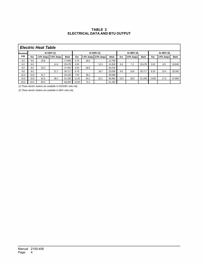
TABLE 2ELECTRICAL DATA AND BTU OUTPUT
lanimoNWK
)1(V042tA )1(V802tA )2(V084tA )2(V064tA
wK spmAhP-1 spmAhP-3 hutB wK spmAhP-1 spmAhP-3 hutB wK spmAhP-3 hutB wK spmAhP-3 hutB
0.5 0.5 8.02 560,71 57.3 0.81 997,21
0.6 0.6 4.41 874,02 05.4 5.21 953,51 0.6 2.7 874,02 25.5 9.6 048,81
0.8 0.8 3.33 403,72 00.6 8.82 874,02
0.9 0.9 7.12 717,03 57.6 7.81 830,32 0.9 8.01 717,03 82.8 4.01 062,82
0.01 0.01 7.14 031,43 05.7 1.63 895,52
0.51 0.51 5.26 1.63 591,15 52.11 1.45 2.13 693,83 0.51 0.81 591,15 08.31 3.71 990,74
0.02 0.02 3.38 062,86 00.51 1.27 591,15
.ylnostinuV802/032nielbaliavaerasretaehcirtceleesehT)1(
.ylnostinuV084nielbaliavaerasretaehcirtceleesehT)2(
Electric Heat Table

Manual 2100-456Page 5
INSTALLATION
2. Before installation, check unit serial plate to insurethat the heater package model that you intend toinstall is listed as a heater package suitable for usewith the unit.
Under no circumstances shall a heater package beinstalled in a unit if the model number of the heaterpackage does not appear on the unit serial plate.
On heater packages with 2 heat strips 10KW heaterfirst in position closest to the outlet air frame. SeeFigures 4C.
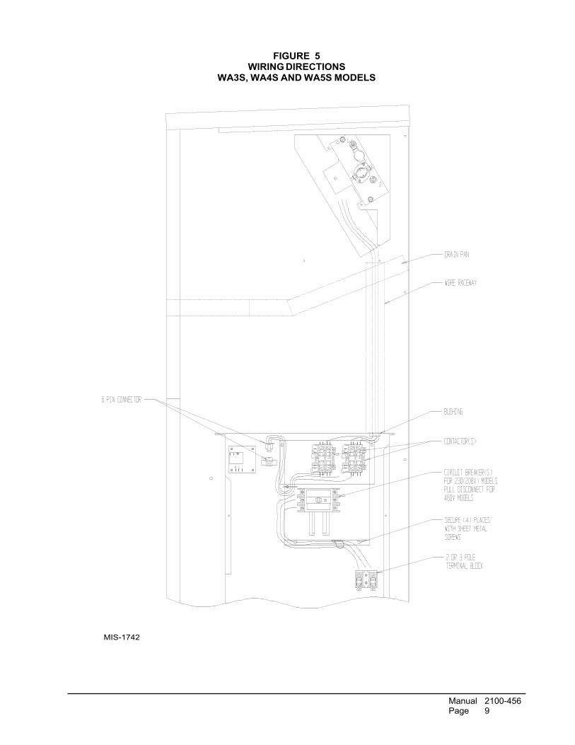
5. Install heater control base into top of control panel asshown in Figure 5. Secure with 4 sheet metal screwsprovided.
6. Plug male 6 pin connector into mating connectormounted in control panel. See Figure 5.
7. Connect red compressor supply lead to L1 ofterminal block. Connect black compressor supplylead to L2 of terminal block. See Figure 5 andwiring diagram.
8. Route wires from heater control base up throughraceway or grommet in top right corner of controlpanel to the heaters. See Figure 5.
9. Wire heater package per wiring diagram suppliedwith this heater package. All wires are stamped withwire numbers that correspond with terminal numberson the wiring diagram and stamped numbers on theheat strip. Low voltage limit switch wires areterminated with insulated quick connect terminals.See Figure 4.
10. Attach adhesive wiring diagram directly above unitwiring diagram on inner control panel cover.
11. Recheck all wiring. Break out appropriate circuitbreaker tabs on inner control panel cover to allowtrip lever to protrude. Replace control panel andheater access panels
12. Resupply power to the unit and check for properoperation.
13. Remark serial plate with self-adhesive label attachedto the front of this manual. See Figure 6.
3. Remove electric heater access panel and controlpanel cover, both inner and outer. See Figure 2.
4. All heaters are installed with the line break limitspositioned to the top of the unit. Install heat strip(s)through heater access opening. Position heat stripsupport rod in heater support hole 1, 2 or 3 asindicated in Table 1 and Figure 3. Secure in placewith 2 sheet metal screws in mounting holes asindicated in Table 1 and Figure 3.
INSTALLATION OF HEATER PACKAGE 1. Disconnect all power to unit before installation.
WARNINGDisconnect all power to unit before installingheater package. Hazard of electrical shock.Failure to disconnect power could result ininjury or death.
WARNINGInstall only heater packages listed on unitserial plate. Hazard of fire or electrical shock.Failure to install listed heater package couldresult in fire, injury or death.

Manual 2100-456Page 6
FIGURE 2INSTALLATION OF HEATER PACKAGE
WA3S, WA4S AND WA5S MODELS
MIS-419

Manual 2100-456Page 7
MIS-358
FIGURE 3ROD SUPPORT AND
SCREW MOUNTING POSITIONS
TABLE 3REFER TO FIGURES 3 AND 4
egakcaPretaeHrebmuNledoM
4erugiFlanimreTretaeH
gniwarDnoitacifitnedI
3erugiFdnatroppuSdoR
noitisoPgnitnuoMwercS
50A-S4AWHE A4 1+1
01A-S4AWHE B4 1+1
51A-S4AWHE C4 2+2
02A-S4AWHE D4 3+3&1+1
50A-S5AWHE A4 1+1
80A-S5AWHE B4 1+1
01A-S5AWHE B4 1+1
51A-S5AWHE C4 2+2
02A-S5AWHE D4 3+3&1+1
60B-S3AWHE B4 1+1
60C-S3AWHE B4 1+1
90C-S3AWHE B4 1+1
60C-S4AWHE B4 1+1
90B-S5AWHE B4 1+1
51B-S5AWHE D4 3+3&1+1
60C-S5AWHE B4 1+1
90C-S5AWHE B4 1+1
51C-S5AWHE D4 3+3&1+1

Manual 2100-456Page 8
FIGURES 4A - 4DHEATER TERMINAL IDENTIFICATION DRAWINGS
Manual 2100-456Page 9
FIGURE 5WIRING DIRECTIONS
WA3S, WA4S AND WA5S MODELS
MIS-1742

Manual 2100-456Page 10
FIG
UR
E 6
MA
RK
ING
SER
IAL
PLA
TE L
AB
EL
MIS
-384

Manual 2100-456Page 11
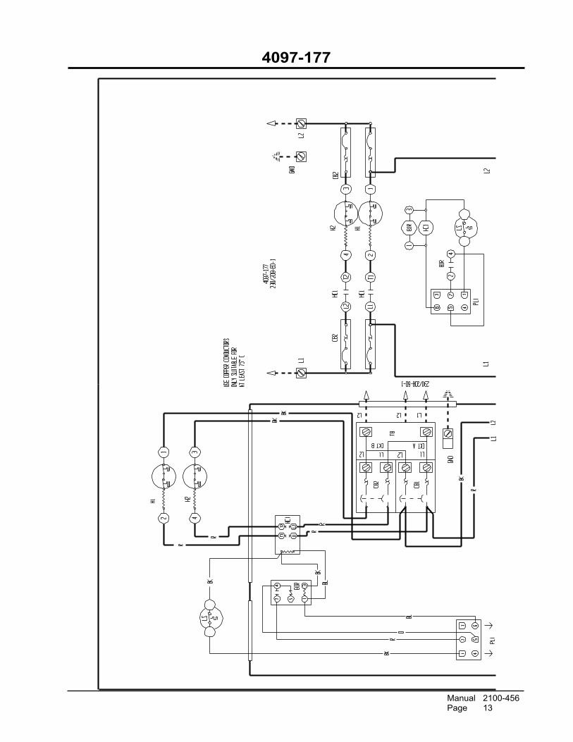
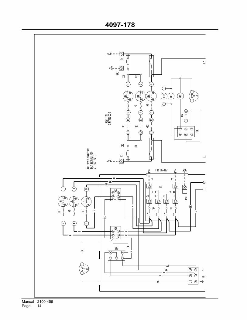
TABLE 4ELECTRIC HEAT WIRING DIAGRAM MODEL USAGE
671-7904 X X
771-7904 X X
871-7904 X X
971-7904 X X
081-7904 X
042-7904 X X X
142-7904 X
043-7904 X X
143-7904 X
EHW
A3S
-B06
EHW
A4S
-A05
EHW
A4S
-A10
EHW
A4S
-A15
EHW
A4S
-A20
EHW
A5S
-A05
EHW
A5S
-A08
EHW
A5S
-A10
EHW
A5S
-A15
EHW
A5S
-A20
EHW
A5S
-B06
EHW
A5S
-B09
EHW
A5S
-B15
EHW
A5S
-C06
EHW
A5S
-C09
EHW
A5S
-C15

Manual 2100-456Page 12
4097-176
Manual 2100-456Page 13
4097-177
Manual 2100-456Page 14
4097-178

Manual 2100-456Page 15
4097-179

Manual 2100-456Page 16
4097-180

Manual 2100-456Page 17
4097-240

Manual 2100-456Page 18
4097-241
Manual 2100-456Page 19
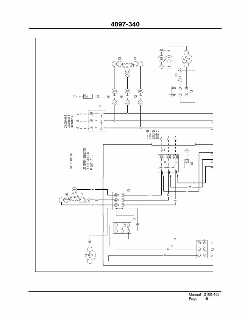
4097-340

Manual 2100-456Page 20
4097-341