Embed Size (px)
Citation preview

INSTALLATION INSTrucTIONS AND OwNer'S MANuAL
uNVeNTeD GAS LOG HeATerMODeLS
INTerMITTeNT MODeLSVFSE-(18,24,30)-1
Vent-Free Burner
This is an unvented gas-fired heater. It uses air (oxy-gen) from the room in which it is installed. Provisions for adequate combustion and ventilation air must be provided. Refer to page 7.
WARNING: If not installed, operated and maintained in accordance with the manufacturer's instructions, this product could expose you to substances in fuel or from fuel combustion which can cause death or seri-ous illness.
WATeR VAPoR: A By-PRoducT of uNVeNTed rOOM HeATerSWater vapor is a by-product of gas combustion. An unvented room heater produces approximately one (1) ounce (30ml) of water for every 1,000 BTu's (.3KW's) of gas input per hour. Refer to page 6.
This appliance may be installed in an aftermarket permanently located, manufactured (mobile) home, where not prohibited by local codes.This appliance is only for use with the type of gas indicated on the rating plate. This appliance is not convertible for use with other gases.Installer: Leave this manual with the appliance.
consumer: Retain this manual for future reference.
— do not store or use gasoline or other flammable vapors and liquids in the vicinity of this or any other appliance.
— WHAT To do If you SMeLL GAS • do not try to light any appliance. • do not touch any electrical switch; do not use
any phone in your building. • Immediately call your gas supplier from a
neighbor’s phone. follow the gas supplier’s instructions.
• If you cannot reach your gas supplier, call the fire department.
— Installation and service must be performed by a qualified installer, service agency or the gas sup-plier.
WARNING: If the information in these instruc-tions are not followed exactly, a fire or explosion may result causing property damage, personal in-jury or loss of life.
EMPIREEMPIREComfort Systems
GAS-FIRED
Page 1

26989-3-0510Page 2
Section PageImportant Safety Information .........................................................................................................................3Safety Information for Users of LP Gas ..........................................................................................................4Introduction......................................................................................................................................................5General Information.........................................................................................................................................6Water Vapor: By Product of Unvented Room Heaters ....................................................................................6Provisions for Adequate Combustion and Ventilation Air ...............................................................................7Clearances .................................................................................................................................................. 7 - 8Combustible Material ......................................................................................................................................9Before Fully Installing the Appliance ..............................................................................................................9Gas Supply .....................................................................................................................................................10Placement of Glowing Embers and Lava Rock .............................................................................................11Operation Instructions/Flame Appearance ....................................................................................................11VFSE Series Remote Electronic Ignition and Control System ............................................................. 12 - 15VFSE-(18,24,30) Lighting Instructions .........................................................................................................16Pilot Flame Characteristics ............................................................................................................................17Cleaning and Servicing ..................................................................................................................................18Wiring ...........................................................................................................................................................18Troubleshooting .............................................................................................................................................19Parts List ........................................................................................................................................................20Parts View ......................................................................................................................................................21Master Parts Distributor List .........................................................................................................................22How to Order Repair Parts ............................................................................................................................22Appliance Service History .............................................................................................................................23
TABLe OF cONTeNTS

26989-3-0510 Page 3
wArNINGWhen used without adequate combustion and ventilation air, heater may give off cARBoN MoNoXIde, an odorless, poisonous gas.
do not install heater until all necessary provisions are made for combustion and ventilation air. consult the written instructions provided with the heater for information concerning combustion and ventilation air. In the absence of instructions, refer to the National fuel Gas code, ANSI Z223.1/NfPA 54, Air for combustion and Ventilation, or applicable local codes.
This heater is equipped with a PILoT LIGHT SAfeTy SySTeM designed to turn off the heater if not enough fresh air is available.
do NoT TAMPeR WITH PILoT LIGHT SAfeTy SySTeM!
If heater shuts off, do not relight until you provide fresh air.If heater keeps shutting off, have it serviced. Keep burner and control compartment clean.
cARBoN MoNoXIde PoISoNING MAy LeAd To deATH.
early signs of carbon monoxide poisoning resemble the flu, with headache, dizziness and/or nausea. If you have these signs, heater may not be working properly. Get fresh air at once! Have heater serviced.Some people – pregnant women, persons with heart or lung disease, anemia, those under the influence of alcohol, those at high altitudes – are more affected by carbon monoxide than others.The pilot light safety system senses the depletion of oxygen at its location. If this heater is installed in a structure having a high vertical dimension, the possibility exists that the oxygen supply at the higher levels will be less than that at the heater. In this type of application, a fan to circulate the structure air will minimize this effect. The use of this fan will also improve the comfort level in the structure. When a fan is used to circulate air, it should be located so that the air flow is not directed at the burner.
• An unvented room heater having an input rating of more than 6,000 Btu per hour shall not be installed in a bathroom
• An unvented room heater having an input rating of more than 10,000 Btu per hour shall not be installed in a bedroom or bath-room.
• Never burn solid fuels in a fireplace where a gas log set is in-stalled.
• due to high temperatures, the appliance should be located out of traffic and away from furniture and draperies.
• do not place clothing or other flammable material on or near the appliance.
• children and adults should be alerted to the hazards of high sur-face temperature and should stay away to avoid burns or clothing ignition.
• young children should be carefully supervised when they are in the same room as the appliance.
• This unit complies with ANSI Z21.11.2 unvented Heaters. check your state or local codes.
• correct installation of logs, proper location of the heater and annual cleaning are necessary to avoid potential problems with sooting. Sooting, resulting from improper installation or operation, can settle on surfaces outside the fireplace.
• Avoid any drafts that could alter burner flame patterns. do not allow fans to blow directly into the fireplace. do not place a blower inside burn box area of firebox. ceiling fans may create drafts that alter burner flame patterns. Sooting and improper burning will occur as a result of drafts.
• WARNING: do not allow fans to blow directly into the fireplace. Avoid any drafts that alter burner flame patterns.
• WARNING: do not use a blower insert, heat exchanger insert or other accessory not approved for use with this heater.
• The installation must conform with local codes or, in the absence of local codes, with the National fuel Gas code, ANSI Z223.1/NfPA54.
• NoTe: Installation and repair should be done by a qualified service person. The appliance should be inspected before use and at least annually by a qualified service person. More frequent cleaning may be required due to excessive lint from carpeting, bedding material, etc. It is imperative that the control compartment, burners and circulating air passageways of the appliance be kept clean.
• Any safety screen or guard removed for servicing an appliance must be replaced prior to operating the appliance. Provide adequate combustion and ventilation air.
• The flow of combustion and ventilation air MuST NoT be ob-structed.
• Provide adequate clearances around air openings into the combus-tion chamber and adequate accessibility clearance for servicing and proper operation. NeVeR obstruct the front opening of the appliance.
• An unvented room heater intended for installation in a solid-fuel burning fireplace shall comply with the following instructions.
• A fireplace screen must be in place when the appliance is operating and, unless other provisions for combustion air are provided, the screen shall have an opening(s) for introduction of combustion air.
• Solid-fuels shall not be burned in a masonry or uL 127 factory-built fireplace in which an unvented room heater is installed.
• Any glass doors shall be fully opened when the appliance is in operation.
• Any outside air ducts and/or ash dumps in the fireplace shall be permanently closed at time of appliance installation.
• WARNING: failure to keep the primary air opening(s) of the burner(s) clean may result in sooting and property damage.
• WARNING: Before installing in a solid-fuel burning fireplace, the chimney flue and firebox must be cleaned of soot, creosote, ashes and loose paint by a qualified chimney cleaner.
IMPoRTANT SAfeTy INfoRMATIoN

26989-3-0510Page 4
Some people cannot smell well. Some people cannot smell the odor of the chemical put into the gas. you must find out if you can smell the odorant in propane. Smoking can decrease your ability to smell. Being around an odor for a time can affect your sensitivity or ability to detect that odor. Sometimes other odors in the area mask the gas odor. People may not smell the gas odor or their minds are on something else. Thinking about smelling a gas odor can make it easier to smell.
The odorant in LP-gas is colorless, and it can fade under some circumstances. For example, if there is an underground leak, the movement of the gas through soil can filter the odorant. Odorants
in LP-Gas also are subject to oxidation. This fading can occur if there is rust inside the storage tank or in iron gas pipes.
The odorant in escaped gas can adsorb or absorb onto or into walls, masonry and other materials and fabrics in a room. That will take some of the odorant out of the gas, reducing its odor intensity.
LP-Gas may stratify in a closed area, and the odor intensity could vary at different levels. Since it is heavier than air, there may be more odor at lower levels. Always be sensitive to the slightest gas odor. If you detect any odor, treat it as a serious leak. Immediately go into action as instructed earlier.
Propane (LP-Gas) is a flammable gas which can cause fires and explosions. In its natural state, propane is odorless and colorless. you may not know all the following safety precau-tions which can protect both you and your family from an accident. Read them carefully now, then review them point
by point with the members of your household. Someday when there may not be a minute to lose, everyone's safety will depend on knowing exactly what to do. If, after reading the following information, you feel you still need more information, please contact your gas supplier.
• Learn to recognize the odor of LP-gas. Your local LP-Gas Dealer can give you a "Scratch and Sniff" pamphlet. Use it to find out what the propane odor smells like. If you suspect that your LP-Gas has a weak or abnormal odor, call your LP-Gas Dealer.
• If you are not qualified, do not light pilot lights, perform service, or make adjustments to appliances on the LP-Gas system. If you are qualified, consciously think about the odor of LP-Gas prior to and while lighting pilot lights or perform-ing service or making adjustments.
• Sometimes a basement or a closed-up house has a musty smell that can cover up the LP-Gas odor. Do not try to light pilot lights, perform service, or make adjustments in an area where the conditions are such that you may not detect the odor if there has been a leak of LP-Gas.
• Odor fade, due to oxidation by rust or adsorption on walls of new cylinders and tanks, is possible. Therefore, people should be particularly alert and careful when new tanks or cylinders are placed in service. Odor fade can occur in new tanks, or reinstalled old tanks, if they are filled and allowed to set too
long before refilling. Cylinders and tanks which have been out of service for a time may develop internal rust which will cause odor fade. If such conditions are suspected to exist, a periodic sniff test of the gas is advisable. If you have any question about the gas odor, call your LP-gas dealer. A periodic sniff test of the LP-gas is a good safety measure under any condition.
• If, at any time, you do not smell the LP-Gas odorant and you think you should, assume you have a leak. Then take the same immediate action recommended above for the occasion when you do detect the odorized LP-Gas.
• If you experience a complete "gas out," (the container is un-der no vapor pressure), turn the tank valve off immediately. If the container valve is left on, the container may draw in some air through openings such as pilot light orifices. If this occurs, some new internal rusting could occur. If the valve is left open, then treat the container as a new tank. Always be sure your container is under vapor pressure by turning it off at the container before it goes completely empty or having it refilled before it is completely empty.
• Do not operate electric switches, light matches, use your phone. Do not do anything that could ignite the gas.
• Get everyone out of the building, vehicle, trailer, or area. Do that IMMEDIATELY.
• Close all gas tank or cylinder supply valves.• LP-Gas is heavier than air and may settle in low areas such
as basements. When you have reason to suspect a gas leak, keep out of basements and other low areas. Stay out until firefighters declare them to be safe.
• Use your neighbor's phone and call a trained LP-Gas service person and the fire department. Even though you may not continue to smell gas, do not turn on the gas again. Do not re-enter the building, vehicle, trailer, or area.
• finally, let the service man and firefighters check for escaped gas. Have them air out the area before you return. Properly trained LP-Gas service people should repair the leak, then check and relight the gas appliance for you.
SoMe PoINTS To ReMeMBeR
NO ODOr DeTecTeD - ODOr FADe
LP-GAS WARNING odoRIf a gas leak happens, you should be able to smell the gas because of the odorant put in the LP-Gas.
That's your signal to go into immediate action!
SAfeTy INfoRMATIoN foR uSeRS of LP-GAS
26989-3-0510 Page 5
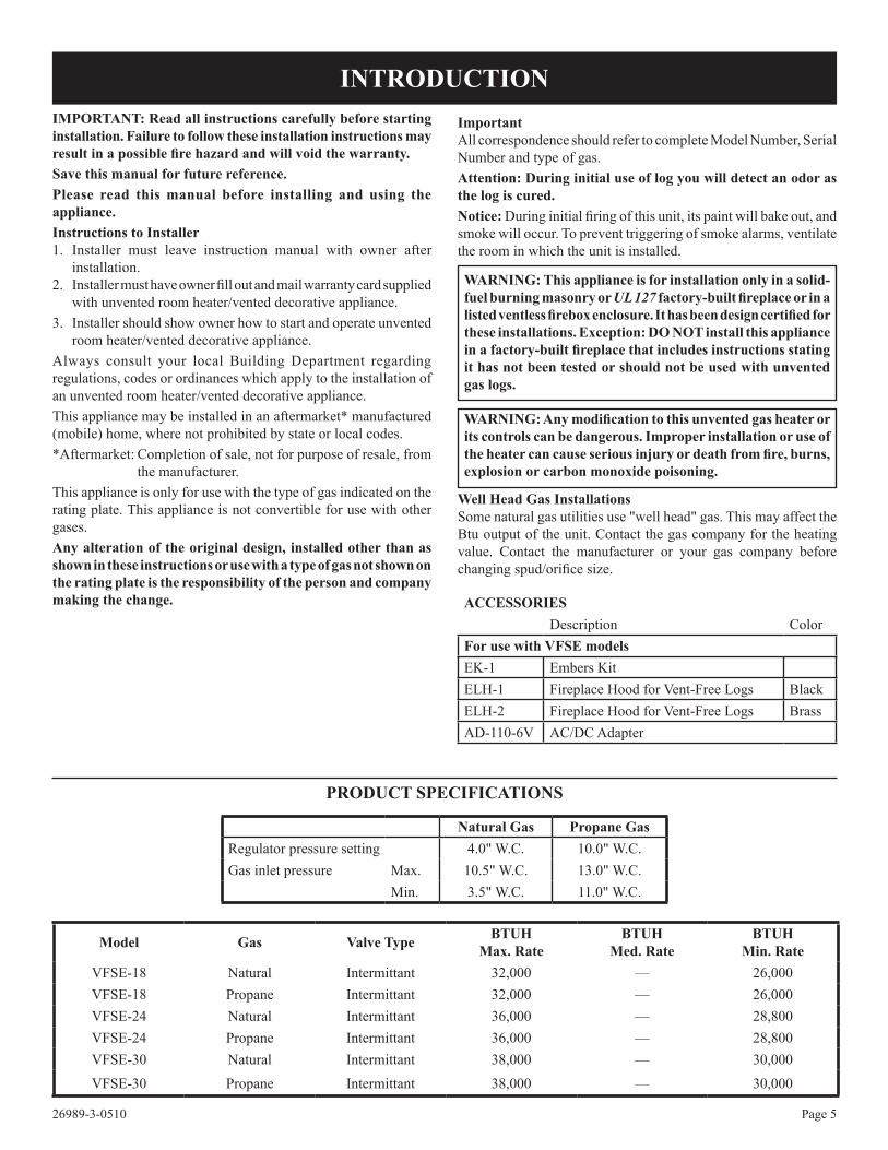
ImportantAll correspondence should refer to complete Model Number, Serial Number and type of gas.Attention: during initial use of log you will detect an odor as the log is cured. Notice: During initial firing of this unit, its paint will bake out, and smoke will occur. To prevent triggering of smoke alarms, ventilate the room in which the unit is installed.
wArNING: This appliance is for installation only in a solid-fuel burning masonry or UL 127 factory-built fireplace or in a listed ventless firebox enclosure. It has been design certified for these installations. exception: do NoT install this appliance in a factory-built fireplace that includes instructions stating it has not been tested or should not be used with unvented gas logs.
WARNING: Any modification to this unvented gas heater or its controls can be dangerous. Improper installation or use of the heater can cause serious injury or death from fire, burns, explosion or carbon monoxide poisoning.
Well Head Gas InstallationsSome natural gas utilities use "well head" gas. This may affect the Btu output of the unit. Contact the gas company for the heating value. Contact the manufacturer or your gas company before changing spud/orifice size.
IMPoRTANT: Read all instructions carefully before starting installation. failure to follow these installation instructions may result in a possible fire hazard and will void the warranty.Save this manual for future reference.Please read this manual before installing and using the appliance.Instructions to Installer1. Installer must leave instruction manual with owner after
installation.2. Installer must have owner fill out and mail warranty card supplied
with unvented room heater/vented decorative appliance.3. Installer should show owner how to start and operate unvented
room heater/vented decorative appliance.Always consult your local Building Department regarding regulations, codes or ordinances which apply to the installation of an unvented room heater/vented decorative appliance.This appliance may be installed in an aftermarket* manufactured (mobile) home, where not prohibited by state or local codes.*Aftermarket: Completion of sale, not for purpose of resale, from
the manufacturer.This appliance is only for use with the type of gas indicated on the rating plate. This appliance is not convertible for use with other gases.Any alteration of the original design, installed other than as shown in these instructions or use with a type of gas not shown on the rating plate is the responsibility of the person and company making the change.
PRoducT SPecIfIcATIoNS
AcceSSOrIeSDescription Color
for use with VfSe modelsEK-1 Embers KitELH-1 Fireplace Hood for Vent-Free Logs BlackELH-2 Fireplace Hood for Vent-Free Logs BrassAD-110-6V AC/DC Adapter
INTrODucTION
Model Gas Valve Type BTuHMax. Rate
BTuHMed. Rate
BTuHMin. Rate
VFSE-18 Natural Intermittant 32,000 — 26,000VFSE-18 Propane Intermittant 32,000 — 26,000VFSE-24 Natural Intermittant 36,000 — 28,800VFSE-24 Propane Intermittant 36,000 — 28,800VFSE-30 Natural Intermittant 38,000 — 30,000
VFSE-30 Propane Intermittant 38,000 — 30,000
Natural Gas Propane GasRegulator pressure setting 4.0" W.C. 10.0" W.C.Gas inlet pressure Max. 10.5" W.C. 13.0" W.C.
Min. 3.5" W.C. 11.0" W.C.

26989-3-0510Page 6
This is an unvented gas-fired heater. It uses air (oxygen) from the room in which it is installed. Provisions for adequate combustion and ventilation air must be provided.Keep room area clear and free from combustible materials, gasoline and other flammable vapors and liquids.Unvented gas heaters are a supplemental zone heater. They are not intended to be a primary heating appliance. Water vapor produced by an unvented heater can create moisture problems in a home when operated for extended periods of time.During manufacturing, fabricating and shipping, various components of this appliance are treated with certain oils, films or bonding agents. These chemicals are not harmful but may produce annoying smoke and smells as they are burned off during the initial operation of the appliance; possibly causing headaches or eye or lung irritation. This is a normal and temporary occurrence.The initial break-in operation should last 2-3 hours with the burner at the highest setting. Provide maximum ventilation by opening windows or doors to allow odors to dissipate. Any odors remaining after this initial break-in period will be slight and will disappear with continued use.This appliance must not be used with glass doors in the closed position. This can lead to pilot outages and severe sooting outside the fireplace.Do not use this room heater if any part has been under water. Immediately call a qualified service technician to inspect the room heater and replace any part of the control system and any gas control which has been under water.
wArNING: This appliance is equipped for (natural or propane) gas. field conversion is not permitted.
Before you get startedCarefully inspect the contents for shipping damage. If any parts are missing or damaged, immediately inform the dealer from whom you purchased the appliance. Do not attempt to install any part of the appliance unless you have all parts in good condition.
Make sure you have received all parts:Check your packing list to verify that all listed parts have been received. You should have the following:• Gas log grate/burner assembly.• Two (2) masonry anchoring screws and two (2) 10 x 1/2" black
sheet metal anchoring screws.
• Plastic bag containing glowing embers (rock wool) for burner coverage.
• Plastic bag containing lava rock.Millivolt controlled heater designed to be operated with optional devices for ON/OFF functions.• Wall switch or thermostat with wire.• Hand held remote control with ON/OFF switch or thermostat.Handle the gas log burner assembly by the grate and legs only. do not pick the unit up by the burner.Gloves are recommended when handling logs to prevent skin irritation. Logs are fragile - Handle with care.Qualified Installing AgencyInstallation and replacement of gas piping, gas utilization equip-ment or accessories and repair and servicing of equipment shall be performed only by a qualified agency. The term "qualified agency" means any individual, firm, corporation, or company that either in person or through a representative is engaged in and is responsible for (a) the installation, testing, or replacement of gas piping or (b) the connection, installation, testing, repair, or servicing of equipment; that is experienced in such work; that is familiar with all precau-tions required, and that has complied with all the requirements of the authority having jurisdiction.
State of Massachusetts: The installation must be made by a licensed plumber or gas fitter in the Commonwealth of Massachusetts.Sellers of unvented propane or natural gas-fired supplemental room heaters shall provide to each purchaser a copy of 527 CMR-30 upon sale of the unit.
The installation must conform with local codes or, in the absence of local codes, with the National Fuel Gas Code, ANSI Z223.1.**Available from the American National Standards Institute, Inc. 11 West 42nd St., New York, N.Y. 10018.
High Altitudes: For altitudes/elevation above 2,000 feet ratings should be reduced at the rate of 4 percent for each 1,000 feet above sea level. Contact the manufacturer.
Water vapor is a by-product of gas combustion. An unvented room heater produces approximately one (1) ounce (30ml) of water for every 1,000 BTU's (.3KW's) of gas input per hour. Unvented room heaters must be used as supplemental heat (a room) rather than a primary heat source (an entire house). In most supplemental heat applications, the water vapor does not create a problem. In most applications, the water vapor enhances the low humidity atmosphere experienced during cold weather.
The following steps will help insure that water vapor does not become a problem. 1. Be sure the heater is sized properly for the application, including
ample combustion air and circulation air.2. If high humidity is experienced, a dehumidifier may be used to
help lower the water vapor content of the air.3. Do not use an unvented room heater as the primary heat source
(an entire house).
GeNerAL INFOrMATION
WATeR VAPoR: A By-PRoducT of uNVeNTed RooM HeATeRS
26989-3-0510 Page 7
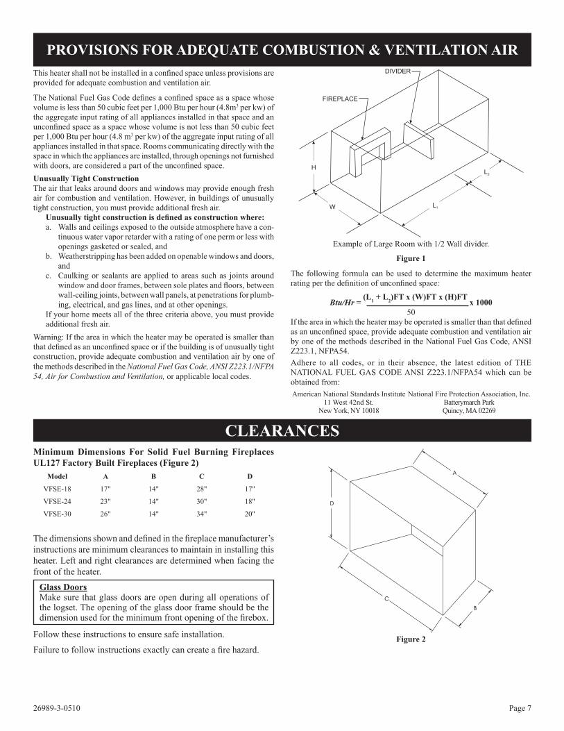
Example of Large Room with 1/2 Wall divider.
figure 1
The following formula can be used to determine the maximum heater rating per the definition of unconfined space:
Btu/Hr = (L1 + L2)fT x (W)fT x (H)fT
x 100050
If the area in which the heater may be operated is smaller than that defined as an unconfined space, provide adequate combustion and ventilation air by one of the methods described in the National Fuel Gas Code, ANSI Z223.1, NFPA54.Adhere to all codes, or in their absence, the latest edition of THE NATIONAL FUEL GAS CODE ANSI Z223.1/NFPA54 which can be obtained from: American National Standards Institute National Fire Protection Association, Inc. 11 West 42nd St. Batterymarch Park New York, NY 10018 Quincy, MA 02269
Minimum dimensions for Solid fuel Burning fireplaces uL127 factory Built fireplaces (figure 2)
figure 2
This heater shall not be installed in a confined space unless provisions are provided for adequate combustion and ventilation air.
The National Fuel Gas Code defines a confined space as a space whose volume is less than 50 cubic feet per 1,000 Btu per hour (4.8m3 per kw) of the aggregate input rating of all appliances installed in that space and an unconfined space as a space whose volume is not less than 50 cubic feet per 1,000 Btu per hour (4.8 m3 per kw) of the aggregate input rating of all appliances installed in that space. Rooms communicating directly with the space in which the appliances are installed, through openings not furnished with doors, are considered a part of the unconfined space.unusually Tight constructionThe air that leaks around doors and windows may provide enough fresh air for combustion and ventilation. However, in buildings of unusually tight construction, you must provide additional fresh air. unusually tight construction is defined as construction where:
a. Walls and ceilings exposed to the outside atmosphere have a con-tinuous water vapor retarder with a rating of one perm or less with openings gasketed or sealed, and
b. Weatherstripping has been added on openable windows and doors, and
c. Caulking or sealants are applied to areas such as joints around window and door frames, between sole plates and floors, between wall-ceiling joints, between wall panels, at penetrations for plumb-ing, electrical, and gas lines, and at other openings.
If your home meets all of the three criteria above, you must provide additional fresh air.
Warning: If the area in which the heater may be operated is smaller than that defined as an unconfined space or if the building is of unusually tight construction, provide adequate combustion and ventilation air by one of the methods described in the National Fuel Gas Code, ANSI Z223.1/NFPA 54, Air for Combustion and Ventilation, or applicable local codes.
PRoVISIoNS foR AdeQuATe coMBuSTIoN & VeNTILATIoN AIR
cLeArANceS
Model A B c D
VFSE-18 17" 14" 28" 17"
VFSE-24 23" 14" 30" 18"
VFSE-30 26" 14" 34" 20"
The dimensions shown and defined in the fireplace manufacturer’s instructions are minimum clearances to maintain in installing this heater. Left and right clearances are determined when facing the front of the heater.
Glass doorsMake sure that glass doors are open during all operations of the logset. The opening of the glass door frame should be the dimension used for the minimum front opening of the firebox.
Follow these instructions to ensure safe installation.
Failure to follow instructions exactly can create a fire hazard.
H
W L1
L2
FIREPLACE
DIVIDER

26989-3-0510Page 8
Mantel clearances with Hood (figure 5)You must have non-combustible materials above the fireplace opening. Non-combustible material must extend at least 8" above fireplace opening. With sheet metal, you must have non-combustible material behind it.Heat resistant materials such as slate and marble must be at least 1/2" thick. Sheet metal should not be installed onto combustible material. Example: A mantel may project from the wall a maximum of 2" at a mini-mum of 13-1/2" above the opening, and a maximum of 6" at a minimum of 15" above the opening.
figure 5If your installation does not meet the above minimum clearances, you must proceed to one of the following steps:• Raise the mantel to the proper height.• Remove the mantel.floor clearance (figure 6)If installing heater at floor level, the minimum distance to combustibles is “0” inches.
HEATER IN FIREPLACEOR FIREBOX
COMBUSTIBLEMATERIAL
figure 6
Sidewall & ceiling clearances (figure 3)
figure 3
The sides of the fireplace opening must be 6" from any combustible wall. The ceiling must be at least 41" for 18", 24" and 30" logs from the fireplace opening.
Mantel clearances Without Hood (figure 4)You must have non-combustible materials above the fireplace opening. Non-combustible material must extend at least 12" above fireplace opening. With sheet metal, you must have non-combustible material behind it.Heat resistant materials such as slate and marble must be at least 1/2" thick. Sheet metal should not be installed onto combustible material.
figure 4If your installation does not meet the above clearances, you must proceed to one of the following steps:• Use a hood• Raise the mantel to the proper height.• Remove the mantel.
cLeARANceS (continued)Non-combust ib le Material distance
Requirements for Safe Installation
12" or more Non-combustible materialLess than 12" Non-combustible material must be extended
to at least 8" with the installation of the op-tional fireplace hood. If you cannot extend non-combustible material at least 8", you must operate heater with flue damper open.
26989-3-0510 Page 9
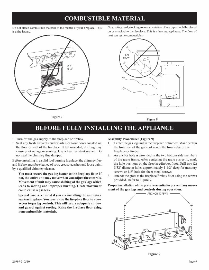
Do not attach combustible material to the mantel of your fireplace. This is a fire hazard.
figure 7
No greeting card, stockings or ornamentation of any type should be placed on or attached to the fireplace. This is a heating appliance. The flow of heat can ignite combustibles.
Figure 8
cOMBuSTIBLe MATerIAL
• Turn off the gas supply to the fireplace or firebox.• Seal any fresh air vents and/or ash clean-out doors located on
the floor or wall of the fireplace. If left unsealed, drafting may cause pilot outage or sooting. Use a heat resistant sealant. Do not seal the chimney flue damper.
Before installing in a solid fuel burning fireplace, the chimney flue and firebox must be cleaned of soot, creosote, ashes and loose paint by a qualified chimney cleaner.
you must secure the gas log heater to the fireplace floor. If not, the entire unit may move when you adjust the controls. Movement of unit may cause shifting of the gas logs which leads to sooting and improper burning. Grate movement could cause a gas leak.Special care is required if you are installing the unit into a sunken fireplace. you must raise the fireplace floor to allow access to gas log controls. This will insure adequate air flow and guard against sooting. Raise the fireplace floor using noncombustible materials.
Assembly Procedure: (figure 9)1. Center the gas log unit in the fireplace or firebox. Make certain
the front feet of the grate sit inside the front edge of the fireplace or firebox.2. An anchor hole is provided in the two bottom side members
of the grate frame. After centering the grate correctly, mark the hole positions on the fireplace/firebox floor. Drill two (2) 5/32" diameter holes approximately 1-1/2" deep for masonry screws or 1/8" hole for sheet metal screws.
3. Anchor the grate to the fireplace/firebox floor using the screws provided. Refer to Figure 9.
Proper installation of the grate is essential to prevent any move-ment of the gas logs and controls during operation.
figure 9
BefoRe fuLLy INSTALLING THe APPLIANce
26989-3-0510Page 10
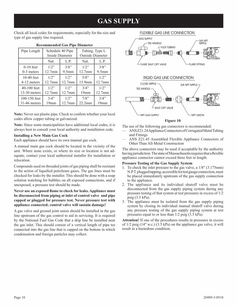
Check all local codes for requirements, especially for the size and type of gas supply line required.
Note: Never use plastic pipe. Check to confirm whether your local codes allow copper tubing or galvanized.Note: Since some municipalities have additional local codes, it is always best to consult your local authority and installation code.Installing a New Main Gas cockEach appliance should have its own manual gas cock.A manual main gas cock should be located in the vicinity of the unit. Where none exists, or where its size or location is not ad-equate, contact your local authorized installer for installation or relocation.Compounds used on threaded joints of gas piping shall be resistant to the action of liquefied petroleum gases. The gas lines must be checked for leaks by the installer. This should be done with a soap solution watching for bubbles on all exposed connections, and if unexposed, a pressure test should be made. Never use an exposed flame to check for leaks. Appliance must be disconnected from piping at inlet of control valve and pipe capped or plugged for pressure test. Never pressure test with appliance connected; control valve will sustain damage!A gas valve and ground joint union should be installed in the gas line upstream of the gas control to aid in servicing. It is required by the National Fuel Gas Code that a drip line be installed near the gas inlet. This should consist of a vertical length of pipe tee connected into the gas line that is capped on the bottom in which condensation and foreign particles may collect.
figure 10The use of the following gas connectors is recommended:— ANS Z21.24 Appliance Connectors of Corrugated Metal Tubing
and Fittings— ANS Z21.45 Assembled Flexible Appliance Connectors of
Other Than All-Metal ConstructionThe above connectors may be used if acceptable by the authority having jurisdiction. The state of Massachusetts requires that a flexible appliance connector cannot exceed three feet in length.Pressure Testing of the Gas Supply System1. To check the inlet pressure to the gas valve, a 1/8" (3.175mm)
N.P.T. plugged tapping, accessible for test gauge connection, must be placed immediately upstream of the gas supply connection to the appliance.
2. The appliance and its individual shutoff valve must be disconnected from the gas supply piping system during any pressure testing of that system at test pressures in excess of 1/2 psig (3.5 kPa).
3. The appliance must be isolated from the gas supply piping system by closing its individual manual shutoff valve during any pressure testing of the gas supply piping system at test pressures equal to or less than 1/2 psig (3.5 kPa).
Attention! If one of the procedures results in pressures in excess of 1/2 psig (14" w.c.) (3.5 kPa) on the appliance gas valve, it will result in a hazardous condition.
GAS SuPPLy
Recommended Gas Pipe diameterPipe Length Schedule 40 Pipe
Inside DiameterTubing, Type L
Outside DiameterNat. L.P. Nat. L.P.
0-10 feet0-3 meters
1/2”12.7mm
3/8”9.5mm
1/2”12.7mm
3/8”9.5mm
10-40 feet4-12 meters
1/2”12.7mm
1/2”12.7mm
5/8”15.9mm
1/2”12.7mm
40-100 feet13-30 meters
1/2”12.7mm
1/2”12.7mm
3/4”19mm
1/2”12.7mm
100-150 feet31-46 meters
3/4”19mm
1/2”12.7mm
7/8”22.2mm
3/4”19mm

26989-3-0510 Page 11
Refer to Parts List, Page 20 to order loose material (rock wool).
Placing Lava Rock in front of Burner on fireplace floor
Spread lava rocks on fireplace floor in front of the burner pan. The lava rocks are for decorative effect and are not required for fireplace operation.
ATTeNTION: DO NOT PLACE LAVA ROCKS ON BURN-ER, LOGS OR ROCK WOOL. THE LAVA ROCKS SHOULD ONLY BE PLACED ON THE FIREPLACE FLOOR.
Flames from the pilot (rear right back side of the pan burner) as well as the main flame should be visually checked as the log set is installed.In normal operation at full rate after 10 to 15 minutes, the flame appearance should be sets of yellow flames.NOTe: All flames will be random by design, flame height will go up and down.Glowing embers (rock wool) can cover the pan burner in between the front and middle logs, but very little is necessary to cover this area. Excess ember material causes the yellow flame to become orange and stringy. Apply just enough to obtain slow glow and a gold yellow flame.Avoid any drafts that alter burner flame patterns. Do not allow fans to blow directly into fireplace. Do not place a blower inside the burner area of the firebox. Ceiling fans may create drafts that alter flame patterns. Sooting and improper burning will result.During manufacturing, fabricating and shipping, various components of this appliance are treated with certain oils, films or bonding agents. These chemicals are not harmful, but may produce annoying smoke and smells as they are burned off during the initial operation of the appliance, possibly causing headaches or eye or lung irritation. This is a normal and temporary occurrence.The initial break-in operation should last 2-3 hours with the burner at the highest setting. Provide maximum ventilation by opening windows or doors to allow odors to dissipate. Any odors remaining after this initial break-in will be slight and will disappear with continued use.
Placement of the glowing embers (rock wool) is very individual and light coverage will provide your best effects. We recommend separation of the rock wool by hand and make your coverage as light and fluffy as possible.
Place just enough embers on the burner to obtain the glow and a gold, yellow flame.
Do not place embers (rock wool) over large ports in rear portion of burner.
Rock wool should not be placed in the area of the pilot assembly.
Replacement of loose material (glowing embers) must be purchased from Empire Comfort Systems, Inc. Application of excess loose material (glowing embers) may adversely affect performance of the heater. WARNING: All previously applied loose material must be removed prior to reapplication.
PLAceMeNT of GLoWING eMBeRS ANd LAVA RocK
oPeRATIoN INSTRucTIoNS/fLAMe APPeARANce
Intermittant - figure 11
26989-3-0510Page 12
VfSe SeRIeS ReMoTe eLecTRoNIc IGNITIoN ANd coNTRoL SySTeM
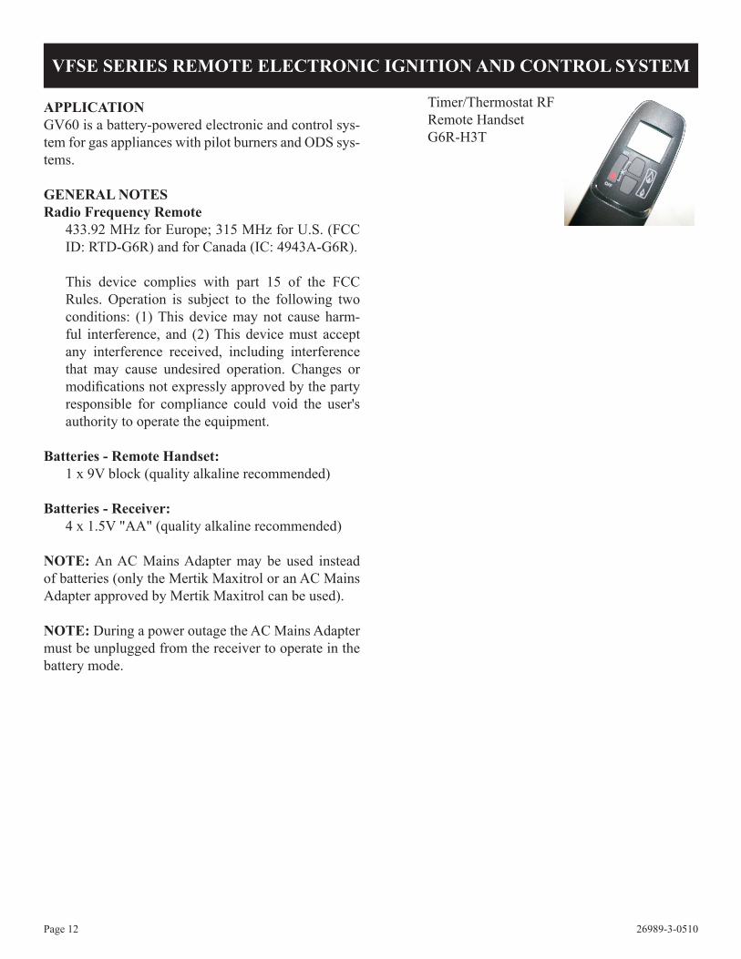
Timer/Thermostat RFRemote HandsetG6R-H3T
APPLIcATIoNGV60 is a battery-powered electronic and control sys-tem for gas appliances with pilot burners and ODS sys-tems.
GeNerAL NOTeSRadio frequency Remote
433.92 MHz for Europe; 315 MHz for U.S. (FCC ID: RTD-G6R) and for Canada (IC: 4943A-G6R).
This device complies with part 15 of the FCC Rules. Operation is subject to the following two conditions: (1) This device may not cause harm-ful interference, and (2) This device must accept any interference received, including interference that may cause undesired operation. Changes or modifications not expressly approved by the party responsible for compliance could void the user's authority to operate the equipment.
Batteries - Remote Handset:1 x 9V block (quality alkaline recommended)
Batteries - Receiver:4 x 1.5V "AA" (quality alkaline recommended)
NOTe: An AC Mains Adapter may be used instead of batteries (only the Mertik Maxitrol or an AC Mains Adapter approved by Mertik Maxitrol can be used).
NOTe: During a power outage the AC Mains Adapter must be unplugged from the receiver to operate in the battery mode.

26989-3-0510 Page 13
Standard, display, Timer/Thermostat Rf Remote Handset
• Simultaneously press and hold the OFF and (large flame) buttons until a short beep confirms the start sequence has be-gun; release buttons.
• Continuing beeps confirm the ignition is in process.
• Once pilot ignition is confirmed, there is main gas flow.
• After the ignition the remote will go automatically into tem-perature control mode.
NOTe: If the pilot does not stay lit after several tries, turn the main valve knob to OFF and follow the instructions "Turn Off Gas to Appliance" See Lighting Instructions.
To TuRN off APPLIANcePress OFF button on remote handset. NoTe: Press (small flame) to turn main gas to pilot gas.
ADJuSTMeNT - FLAMe HeIGHTStandard, display, Timer/Thermostat Rf Remote Handsets
• In standby mode: Press (large flame) to increase flame height.
• Press (small flame) to decrease flame height or to set appli-ance at pilot flame.
• For fine adjustment tap the large/small flames.
Quick flame Adjust - display, Timer/Thermostat Rf Remote Handset
• If (large flame) or (small flame) are pressed for 0.5 seconds, the motor will turn the valve to high fire or pilot flame.
NOTe: If the appliance will not operate, follow the instructions "TURN OFF GAS TO APPLIANCE" (See page 16).
SeTTING °c/24 HouR oR °f/12 HouR cLocKdisplay, Timer/Thermostat Rf Remote Handsets
• Press OFF and (small flame) until display changes from Fahrenheit/12 hour clock to Celsius/24 hour clock and vice versa.
AuToMATIc oPeRATIoN
wArNINGWiring of valve and receiver must be completed before start-ing ignition. Failure to do so could damage the electronics.
SeTTING THe eLecTrONIcS cODeNOTe: The remote control and receiver are pre-programmed at the factory. However, if for some reason they do not communicate to each other, follow these steps to re-program.
Radio frequency Remote
A code is selected automatically for all Mertik Maxitrol electron-ics from among 65,000 random codes available. The receiver has to learn the code of the handset:
• Press and hold the receiver's reset button (see figure 12) until you hear two (2) beeps. After the second, longer beep, release the reset button.
• Within the subsequent 20 seconds press the (small flame) button on the remote handset until you hear an additional long beep confirming the code is set.
NOTe: This is a one time setting only, and is not required when changing the batteries in the remote or receiver.
To TuRN oN APPLIANceWARNING
When pilot ignition is confirmed, motor turns automatically to maximum flame height.
• Turn MANUAL knob to the ON, full counterclockwise position (See Figure 15).
• Place ON/OFF switch (if equipped) in (ON position).
figure 12
figure 13 figure 14
VfSe SeRIeS ReMoTe eLecTRoNIc IGNITIoN ANd coNTRoL SySTeM

26989-3-0510Page 14
NOTe: The display shows the set temperature every 30 sec-onds.
SeTTING THe TeMPeRATuRe• Select either the TEMP MODE or the TEMP MODE by
briefly pressing the SET button.• Hold the SeT button until the TEMP display flashes.
• Set the desired temperature with (large flame) or (small flame).
• Press OFF or simply wait to complete programming.• NOTe: When the desired room temperature is SET on the
hand held remote, the burner will automatically turn on when the room temperature drops 3 degrees Fahrenheit (F) below the SET temperature. The remote system will turn the burner off when the room temperature reaches 3 degrees Fahrenheit (F) above the SET temperature. The pilot will remain lit be-tween burner cycles when using the thermostatic remote con-trol feature.
SeTTING THe TIMer• Select Timer mode by briefly pressing the SET button.• Press and hold the SET button until the P1 (sun symbol)
is displayed and the time flashes. Set the hour by pressing the
(large flame) and set the minutes by pressing the (small flame).
• Briefly press SeT button for the next burner cycle time.• Example: P1 (moon symbol) continue through P2 (sun
symbol) and P2 (moon symbol).• Once all four (4) times are set, press OFF or simply wait to
complete programming.
MANuAL oPeRATIoNFollow appliance lighting instructions for gaining access to the gas control and the pilot burner. Access to the pilot burner is only required for ignition with a match.
When turning main valve knob, do not force. Knob has a slip clutch that clicks until the end stops are reached. This allows for manual flame height adjustment as well as adjustment to pilot standby position.
1. SToP! Read the safety information included before proceed-ing.
2. Turn main valve knob to the OFF, full clockwise position.
3. Turn MANUAL knob to the MAN, full clockwise position.
4. Place ON/OFF switch (if equipped) in O (OFF position).5. Wait five (5) minutes to clear out any gas. Verify that no gas
is in the area around the appliance, including near the floor. If you detect gas SToP! Follow "A" in the safety information on page 18. If no gas is present, proceed to step 6.
6. Place ON/OFF switch in (ON position).
SeTTING THe TIMedisplay, Timer/Thermostat Rf Remote Handsets
• The display will flash after either: a. Installing the battery or
b. Simultaneously pressing the (large flame) and (small flame)
• Press (large flame) to set the hour and the (small flame) to set the minute.
• Press OFF to return to manual mode or simply wait and it will automatically return to the manual mode.
cHANGING THe Mode of oPeRATIoNBriefly pressing the SeT button changes the mode of operation in the following order:
NOTE: MANUAL mode can also be reached by pressing either
the (large flame) or the (small flame).and back to
MAN Mode - Manual flame Height Adjustment
• Press (large flame) to turn on the main burner.
• Press (large flame) to increase the flame height.• Press (small flame) to decrease the flame height or to go to
pilot standby position.
NOTe: While pressing either button a symbol indicating trans-mission appears on the display. The receiver confirms transmission with a beep.
TEMP - daytime Temperature Mode(appliance must be in standby mode; pilot ignited): The room temperature is measured and compared to the set temperature. The flame height is then automatically adjusted to achieve the Daytime set temperature.
TEMP - Nighttime Setback Temperature Mode(appliance must be in standby mode; pilot ignited):The room temperature is measured and compared to the Night-time Setback temperature. The flame height is then automatically adjusted to achieve the Nighttime Setback temperature.
TIMER - Timer Mode(appliance must be in standby mode; pilot ignited):The timer setting allows you to set two (2) burner TEMP times and two (2) burner TEMP times every 24 hours.For TEMP to operate as a thermostat, TEMP must be set at 40°F (4°C) or higher.If the TEMP setting is decreased to ≤ 39°F (3.9°C), the motor will turn the valve to the standby position in the moon times and await the next burner TEMP cycle.
MAN TEMPTEMP TIMER MAN
VfSe SeRIeS ReMoTe eLecTRoNIc IGNITIoN ANd coNTRoL SySTeM

26989-3-0510 Page 15
7. With the MANUAL knob in MAN position a manual pi-lot valve operator and piezo igniter are accessible.
Ignition with match: Fully push down manual pilot valve operator and hold in, to start pilot gas flow. Immediately light the pilot with a match, while continuing to hold in the manual pilot valve operator for about one (1) min-ute after the pilot is lit. Release manual pilot valve operator. If pilot does not stay lit, wait five (5) minutes and repeat.
Ignition with piezo igniter: Change the ignition cable from the receiver to the valve. Use the push piezo igniter to ignite. If pilot does not stay lit, wait five (5) minutes and repeat. NOTe: If the pilot does not stay lit after several tries, turn the gas control knob (main valve knob) to OFF and proceed to step 11.
8. If applicable, reinstall the top cover on the burner base before proceeding.
9. Turn MANUAL knob to the ON, full counterclockwise position.
10. Turn main valve knob to the full ON, full coun-terclockwise position.
11. If the appliance will not operate, follow the instructions "TURN OFF GAS TO APPLIANCE" and call the service technician or gas supplier.
TuRN off GAS To APPLIANce• Press OFF button on remote.• Follow appliance instructions for gaining accessibility to the
gas control.• Place ON/OFF switch in O (off position).• Turn main valve knob to the OFF full clockwise
position.• Replace appliance top cover.
MISceLLANeOuSLow Battery IndicationReceiver: three short beeps will sound when motor turnsRemote with display: "BATT" will appear on display
NOTe: Thermostatic Displays/Handsets: If the battery of the handset is low or if the transmitter is out of the commu-nication range, the motor turns down the valve to pilot gas after 6 hours.
NOTe: With very low battery the GV60 system shuts off the fire completely. This will not happen if the power supply is interrupted.
Battery replacementBattery replacement is recommended at the beginning of each heating season. Do not use metal tools to remove batteries. Using a metal tool could cause a short that may damage the receiver.
Location of ReceiverWhen the RF-receiver is placed in the appliance, the surrounding metal can reduce reception considerably. The position of th an-tenna on the receiver also influences reception. It is recommended to straighten the antenna. The antenna must not come in contact or cross the ignition wire, this may render the receiver inoperable.
NOTe: Keep receiver free from debris and dirt. Protect the re-ceiver with a plastic bag until all construction is com-plete.
PIEZO IGNITER
ON/OFF SWITCHIN POSITIONON
8 WIRERECEIVER JACK
MICROSWITCH
MAIN VALVE KNOBIN POSITIONOFF
MANUAL PILOTVALVE OPERATOR
MANUAL KNOBIN POSITIONMAN
CONNECTIONPIEZO IGNITERTAB 2.8 X 0.8 mm
CUTOUT FOR PILOTGAS ADJUSTMENT
MANUAL KNOBIN POSITION FORAUTOMATIC IGNITION
VfSe SeRIeS ReMoTe eLecTRoNIc IGNITIoN ANd coNTRoL SySTeM
figure 15
figure 16

26989-3-0510Page 16
TO TURN OFF GAS TO APPLIANCE
foR youR SAfeTy ReAd BefoRe LIGHTING
A. This appliance has a pilot which must be lighted by hand. When lighting the pilot, follow these instructions exactly.
B. BeFOre LIGHTING smell all around the appliance area for gas. Be sure to smell next to the floor because some gas is heavier than air and will settle on the floor.
WHAT To do If you SMeLL GAS• do not try to light any appliance.• do not touch any electrical switch; do not use any phone in your building.• Immediately call your gas supplier from a neighbor's
phone. follow the gas supplier's instructions.
• If you cannot reach your gas supplier, call the fire department.
c. use only your hand to push in or turn the gas control knob. Never use tools. If the knob will not push in or turn by hand, don't try to repair it; call a qualified service technician. force or attempted repair may result in a fire or explosion.
d. do not use this appliance if any part has been under water. Immediately call a qualified service technician to inspect the appliance and to replace any part of the control system and any gas control which has been under water.
LIGHTING INSTRUCTIONS
VfSe-(18,24,30) LIGHTING INSTRucTIoNS
wArNING: If you do not follow these instructions exactly, a fire or explosion may result causing property damage, personal injury or loss of life.
1. STOP! Read the safety information above.2. Open bottom louver assembly (if applicable).3. Press the "I/O" (ON/OFF) button on the valve face to
"OFF."4. Wait five (5) minutes to clear out any gas, then smell for gas
including near the floor. If you smell gas, STOP! Follow "B" in the safety information above. If you don't smell gas, go to the next step.
LIGHTING PRoceduRe - HANdSeT MeTHod1. Turn control arrow on valve face to "ON." Press the "I/O"
button to "I." Press the "OFF" and "UP" buttons on the handset, firmly at the same time. A long "Beep" will sound, followed by 5 short "beeps." Ignitor will spark and will con-tinue until pilot is lit. For full Remote Control operation see Appliance Installation manual.
LIGHTING PRoceduRe - MANuAL MeTHod1. Press teh "I/O" (ON/OFF) button to "I."2. Turn control arrow on valve face to "MAN."3. Using a small bladed screwdriver, press and hold button
within hole on control. Manually depress piezo igniter but-ton to light pilot. If pilot does not light, steps 2-3 can be im-mediately repeated. If the pilot will not stay lit after several tries, follow the instructions "To Turn Off Gas to Appliance" and call your service technician or gas supplier.
4. When the pilot is lit and stable, turn flame height control knob counterclockwise and the main burner will ignite. To adjust flame height, turn flame height control knob.
“I/O”(ON/OFF)SWITCH
CORRECT PILOT FLAME INCORRECT PILOT FLAME
THERMOCOUPLE(NATURAL)
ELECTRODE
PILOT
THERMOCOUPLE(LPG)
THERMOCOUPLE(NATURAL)
ELECTRODE
PILOT
THERMOCOUPLE(LPG)
MAN
NO
75 OF
SET
OFF
Press firmlyat same time
PRESS IN& HOLD
MAN
TO IGNITE PILOTHANDSET MODE
To Ignite BurnerMANUAL MODE
PIEZOIGNITER
MANuAL MODe - To turn off main burner, tun flame height control knob fully clockwise . To fully shut down, press "I/O" button to "O."HANDSeT MODe - Press "OFF" button on handset. To fully shut down, press "I/O" button to "O."
26989-3-0510 Page 17
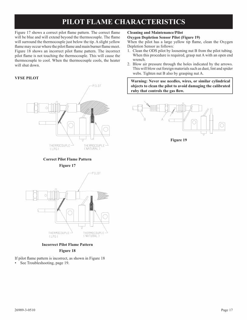
Figure 17 shows a correct pilot flame pattern. The correct flame will be blue and will extend beyond the thermocouple. The flame will surround the thermocouple just below the tip. A slight yellow flame may occur where the pilot flame and main burner flame meet. Figure 18 shows an incorrect pilot flame pattern. The incorrect pilot flame is not touching the thermocouple. This will cause the thermocouple to cool. When the thermocouple cools, the heater will shut down.
VfSe PILoT
correct Pilot flame Patternfigure 17
Incorrect Pilot flame Patternfigure 18
If pilot flame pattern is incorrect, as shown in Figure 18• See Troubleshooting, page 19.
cleaning and Maintenance/Pilotoxygen depletion Sensor Pilot (figure 19)When the pilot has a large yellow tip flame, clean the Oxygen Depletion Sensor as follows:1. Clean the ODS pilot by loosening nut B from the pilot tubing.
When this procedure is required, grasp nut A with an open end wrench.
2. Blow air pressure through the holes indicated by the arrows. This will blow out foreign materials such as dust, lint and spider webs. Tighten nut B also by grasping nut A.
Warning: Never use needles, wires, or similar cylindrical objects to clean the pilot to avoid damaging the calibrated ruby that controls the gas flow.
figure 19
PILoT fLAMe cHARAcTeRISTIcS

26989-3-0510Page 18
Annual inspection and cleaning by your dealer or qualified service technician is recommended to prevent malfunction and/or sooting.
TurN OFF HeATer AND ALLOw TO cOOL BeFOre cLeANING.Remove logs, handling carefully by holding gently at each end. Gloves are recommended to prevent skin irritation from ceramic fibers. If skin becomes irritated, wash gently with soap and water. Refer to manual for correct log placement.
PeRIodIc cLeANING – Refer to parts diagram for location of items discussed below.• Do not use cleaning fluid to clean logs or any part of heater.• Logs - brush with soft bristle brush or vacuum with brush
attachment.• Remove loose particles and dust from the burner areas,
controls, piezo covers and grate. Don’t remove media from inside burner box.
• Inspect and clean burner air intake hole. Remove lint or particles with brush. Failure to keep air intake hole clean will result in sooting and poor combustion.
ANNuAL cLeANING/INSPecTIoN – Refer to parts diagram for location of items discussed below.
• Inspect and clean burner air intake hole. Remove lint or particles with vacuum or brush. Failure to keep air intake
hole clean will result in sooting and poor combustion.• Inspect and clean all burner ports.• Inspect ODS pilot for operation and accumulation of lint at air
intake holes.• Verify flame pattern and log placement for proper operation.• Verify smooth and responsive ignition of main burner.• Check level of ceramic media in burner. Burner should be full,
up to the level of openings in burner top.
cLeANING AND SerVIcING
wIrING
MA
GR
MO
SW
PA
NE
L
SW TCSPARK
O
I
IGNITION CABLE
THERMOCOUPLE
RF ANTENNA
THERMO CURRENT
CABLE #1
ON/OFF SWITCH
8 WIRE CABLE
INTERRUPTER
BLOCK
COMBINATION CONTROL
MANUAL KNOB
PIEZO IGNITER
MAIN VALVE KNOB
CONNECTION FOR
MANUAL IGNITION
THERMO CURRENT
CABLE #2 OR ON/OFF
SWITCH WITH SOLDERED CABLE
BUTTON “RESET”
BATTERY
COMPARTMENT
VfSe Wiring diagram figure 20

26989-3-0510 Page 19
If the gas quality is bad, your pilot may not stay lit, the burners may produce soot and the heater may backfire when lit. If the gas quality or pressure is low, contact your local gas supplier immediately.
1. When ignitor button is pressed, there is no spark at odS/pilot. a. Ignitor electrode positioned wrong - Replace pilot.b. Ignitor electrode is broken - Replace pilot.c. Ignitor electrode not connected to ignitor cable - Reconnect
ignitor cable.d. Ignitor cable pinched or wet. Keep ignitor cable dry - Free
ignitor cable if pinched by any metal or tubing. e. Broken ignitor cable - Replace ignitor cable.f. Bad piezo ignitor - Replace piezo ignitor.
2. Appliance produces unwanted odors.a. Appliance burning vapors from paint, hair spray, glues,
etc. - Ventilate room. Stop using odor causing products while heater is running.
b. Gas leak - Locate and correct all leaks. 3. Appliance shuts off during use. (Pilot and main burner are
off.)a. Not enough fresh air is available for ODS/pilot to operate
- Open window and/or door for ventilation.b. Low line pressure - Contact local gas company.c. ODS/pilot is partially clogged - Clean ODS/pilot.d. Defective thermocouple - Replace pilot.
4. Appliance shuts off during use. (Pilot stays on.)a. Low line pressure - Check line pressure to the valve.
5. Gas odor even when control knob is in off position.a. Gas leak - Locate and correct all leaks.b. Control valve defective - Replace control valve.
6. When ignitor button is pressed, there is spark at odS/pilot, but no ignition.a. Gas supply turned off or manual shutoff valve closed - Turn
on gas supply or open manual shutoff valve.b. Control knob not in PILOT position - Turn control knob
to PILOT position.c. Control knob not pressed in while in PILOT position - Press
in control knob while in PILOT position.d. Air in gas lines when installed - Continue holding down
control knob. Repeat igniting operation until air is removed.
e. ODS/pilot is clogged - Replace ODS/pilot assembly or get it serviced.
g. Gas regulator setting is not correct - Replace gas regulator.
7. odS/pilot lights but flame goes out when control knob is released.a. Control knob not fully pressed in - Press in control knob
fully.b. Control knob not pressed in long enough - After ODS/pilot
lights, keep control knob pressed in 30 seconds.c. Manual Shutoff valve not fully open - Fully open manual
shutoff valve.d. Thermocouple connection loose at control valve - Hand
tighten until snug, then tighten 1/4 turn more.
e. Pilot flame not touching thermocouple, which allows thermocouple to cool, causing pilot flame to go out. This problem could be caused by either low gas pressure or dirty or partially clogged ODS/pilot - Contact local gas company.
f. Thermocouple damaged - Replace thermocouple.h. Control valve damaged - Replace control valve.
8. Burner does not light after odS/pilot is lit.a. Burner orifice clogged - Clean burner or replace main burner
orifice.b. Burner orifice diameter is too small - Replace burner
orifice.c. Inlet gas pressure is too low - Contact qualified service
person. 9. If burning at main burner orifice occurs (a loud, roaring
blow torch noise).a. You must turn off burner assembly and contact a qualified
service person.b. Manifold pressure is too low - Contact local gas
company.c. Burner orifice clogged - Clean burner or replace burner
orifice. 10. Logs appear to smoke after initial operation.
a. Vapors from paint or curing process of logs - Problem will stop after a few hours of operation. Run the heater with the damper open if you have one, or open a window for the first few hours.
Log heater is intended to be smokeless. Turn OFF heater and call qualified service person.
11. Heater produces a whistling noise when main burner is lit.a. Turning control knob to HIGH position when main burner
is cold - Turn control knob to LOW position and let warm up for a minute.
b. Air in gas line - Operate burner until air is removed from line. Have gas line checked by local gas company.
c. Dirty or partially clogged burner orifice - Clean burner or replace burner orifice.
12. No gas to pilot.a. LP-regulator shut down due to inlet pressure too high -
Verify LP tank regulator is installed and set at 11" to 13" w.c. Replace regulator on heater.
TrOuBLeSHOOTINGSyMPToMS - PoSSIBLe cAuSeS ANd coRRecTIoN

26989-3-0510Page 20
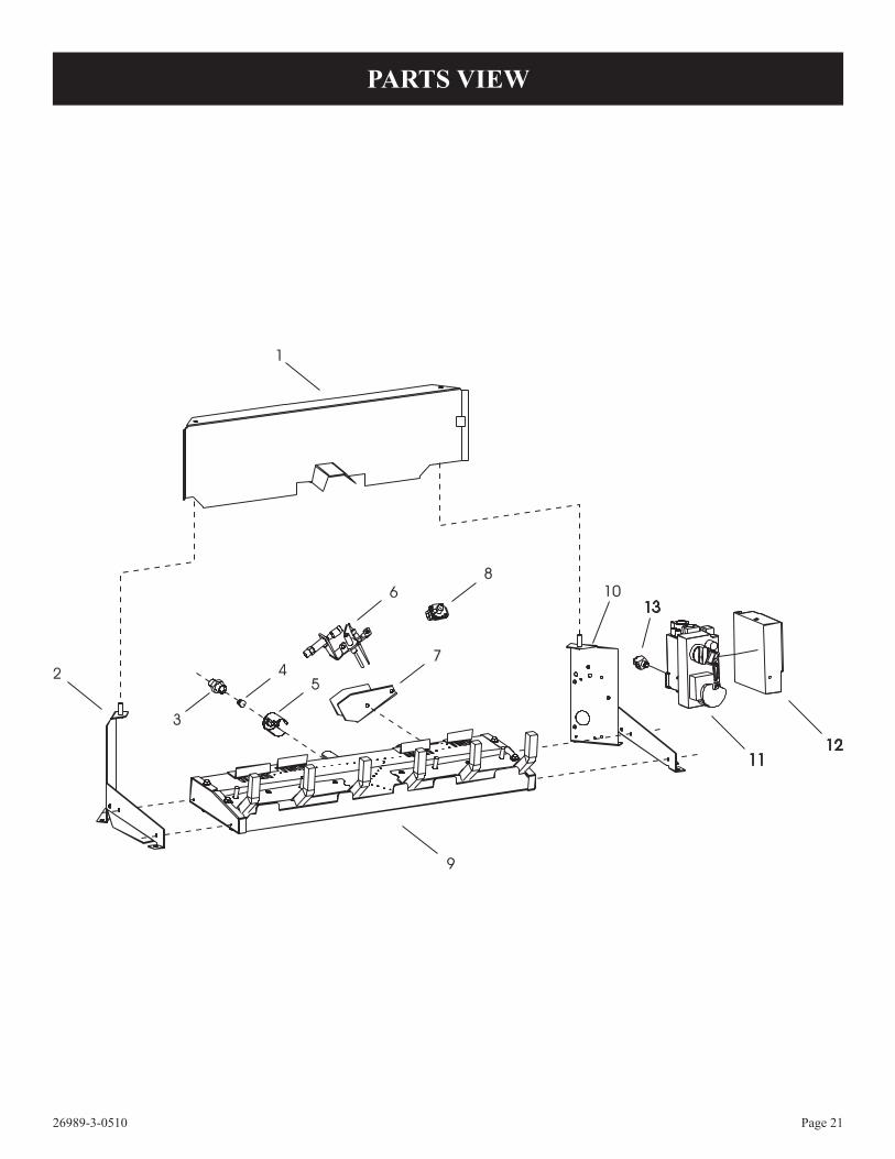
Attention: When ordering parts, it is very important that part number and description of part coincide.
USE ONLY MANUFACTURER'S REPLACEMENT PARTS. USE OF ANY OTHER PARTS COULD CAUSE INjURY OR DEATH.
PARTS LIST
INdeX No.
PART No.
deScRIPTIoN
1 15426 REAR LOG SUPPORT (VFSE-18)1 15427 REAR LOG SUPPORT (VFSE-24)1 15428 REAR LOG SUPPORT (VFSE-30)2 11376 BURNER SUPPORT - LEFT
(VFSE-(18,24,30))3 P-200 ORIFICE FITTING4 P-250 ORIFICE - LP (VFSE-18)4 P-245 ORIFICE - LP (VFSE-24)4 P-265 ORIFICE - LP (VFSE-30)4 P-243 ORIFICE - NAT (VFSE-18)4 P-244 ORIFICE - NAT (VFSE-24)4 P-211 ORIFICE - NAT (VFSE-30)5 R-5675 AIR SHUTTER - LP5 R-5676 AIR SHUTTER - NAT6 R5170 PILOT, LP6 R5171 PILOT, NAT7 11833 PILOT SHIELD (NAT ONLY)8 R7063 PILOT REGULATOR (NAT ONLY)9 14033 BURNER ASSEMBLY (VFSE-18) 9 14035 BURNER ASSEMBLY (VFSE-24) 9 14037 BURNER ASSEMBLY (VFSE-30)
10 11308 BURNER SUPPORT-RIGHT11 R10563 VALVE, MAXITROL (LP)11 R10562 VALVE, MAXITROL (NAT)12 R10566 ELECTRONIC CONTROL 13 R10572 CONNECTOR, THERMOCOUPLE
NS R10559 BATTERY, 9-VOLTNS 12389 CERAMIC MEDIANS R2809 DAMPER CLAMP (INCLUDED IN
HARDWARE PACKAGE)NS 11788 DECORATIVE ROCK (2 REQ’D)NS R10518 FASTENER, HOOKNS R10519 FASTENER, LOOPNS R10573 HEX PLUG, 1/2 NPTNS R10568 IGNITER WIRE, MAXITROLNS R10564 REMOTE CONTROL KIT
(INCLUDES TRANSMITTER, HAR-NESS AND RECEIVER)
NS R10565 REMOTE CONTROL THERMOSTAT NS 15999 ROCK WOOL (VFSE-18)NS 15970 ROCK WOOL (VFSE-(24,30)) NS R10569 SWITCH AND WIRE ASSEMBLYNS 14040 TUBING ASSEMBLY - NAT
VALVE TO REGULATORNS 14041 TUBING ASSEMBLY - NAT
REGULATOR TO PILOTNS 11291 TUBING ASSEMBLY-
VALVE TO BURNER NS 11335 TUBING ASSEMBLY- LP
VALVE TO PILOT NS R10570 WIRE ASSY, THERMOCOUPLENS R10567 WIRE HARNESS (8 PIN)
NS - NOT SHOWN
INdeX No.
PART No.
deScRIPTIoN
26989-3-0510 Page 21
13
1112
PARTS VIeW

26989-3-0510Page 22
To Order Parts Under Warranty, please contact your local Empire dealer. See the dealer locator at www.empirecomfort.com. To provide warranty service, your dealer will need your name and address, purchase date and serial number, and the nature of the problem with the unit. To Order Parts After the Warranty Period, please contact your dealer or one of the Master Parts Distributors listed below. This list grows from time to time. For the current list, please click on the Master Parts button at www.empirecomfort.com.Please note: Master Parts Distributors are independent businesses that stock the most commonly ordered Original Equipment repair parts for Heaters, Grills, and Fireplaces manufactured by Empire Comfort Systems Inc.
Star-fire distributors1355 Evans AvenueAkron, OH 44305
Phone: 330-630-2794Toll free: 800-875-6220fax: 330-633-8701Parts: Heater & Hearth and Grills
dey distributing1401 Willow Lake BoulevardVadnais Heights, MN 55101
Phone: 651-490-9191Toll free: 800-397-1339Website: www.deydistributing.comParts: Heater & Hearth
east coast energy Products10 East Route 36West Long Branch, Nj 07764
Phone: 732-870-8809Toll free: 800-755-8809fax: 732-870-8811Website: www.eastcoastenergy.comParts: Heater & Hearth and Grills
Victor division of f. W. Webb company200 Locust StreetHartford, CT 06114
Phone: 860-722-2433Toll free: 800-243-9360fax: 860-293-0479Toll free fax: 800-274-2004Websites: www.fwwebb.com & www.victormfg.comParts: Heater & Hearth and Grills
MASTeR PARTS dISTRIBuToR LIST
Parts Not under WarrantyParts can be ordered through your Service Person, Dealer, or a Master Parts Distributor. See this page for the Master Parts Distribu-tors list. For best results, the service person or dealer should order parts through the distributor. Parts can be shipped directly to the service person/dealer.Warranty PartsWarranty parts will need a proof of purchase and can be ordered by your Service Person or Dealer. Proof of purchase is required for warranty parts.All parts listed in the Parts List have a Part Number. When ordering parts, first obtain the Model Number from the name plate on your equipment. Then determine the Part Number (not the Index Number) and the Description of each part from the following appropriate illustration and list. Be sure to give all this information . . .
Appliance Number Part Description
Appliance Serial Number Part Number
Type of Gas (Propane or Natural)
Do not order bolts, screws, washers or nuts. They are standard hardware items and can be purchased at any local hardware store. Shipments contingent upon strikes, fires and all causes beyond our control.
HoW To oRdeR RePAIR PARTS
26989-3-0510 Page 23
APPLIANce SeRVIce HISToRyDate dealer Name Service Technician Name Service Performed/Notes

26989-3-0510Page 24
EMPIREEMPIREComfort Systems
Empire Comfort Systems Inc.918 Freeburg Ave. Belleville, IL 62220
If you have a general question about our products, please e-mail us at [email protected]. If you have a service or repair question, please contact your dealer.
www.empirecomfort.com