Embed Size (px)
Citation preview
Code No. 0816321Rev. 3 (08/10)
INSTALLATION INSTRUCTIONS FOR BATTERY POWEREDSENSOR ACTIVATED LAVATORY FAUCETS
LIMITED WARRANTY
Sloan Valve Company warrants its EBF-615 and EBF-650 Faucets to be made of first class materials, free from defects of material or workmanship under normaluse and to perform the service for which they are intended in a thoroughly reliable and efficient manner when properly installed and serviced, for a period of threeyears (1 year for special finishes) from date of purchase. During this period, Sloan Valve Company will, at its option, repair or replace any part or parts which proveto be thus defective if returned to Sloan Valve Company, at customer’s cost, and this shall be the sole remedy available under this warranty. No claims will be allowedfor labor, transportation or other incidental costs. This warranty extends only to persons or organizations who purchase Sloan Valve Company’s products directly fromSloan Valve Company for purpose of resale. This warranty does not cover the life of the batteries.
THERE ARE NO WARRANTIES WHICH EXTEND BEYOND THE DESCRIPTION ON THE FACE HEREOF. IN NO EVENT IS SLOAN VALVE COMPANY RESPONSIBLE FORANY CONSEQUENTIAL DAMAGES OF ANY MEASURE WHATSOEVER.
PRIOR TO INSTALLATION
EBF-615Pedestal,
Battery Powered,Sensor ActivatedLavatory Faucet
EBF-6504” Centerset,
Battery Powered,Sensor ActivatedLavatory Faucet
Prior to installing the Sloan EBF-615 or EBF-650 faucet, install the items listed below. Also, refer to rough-in illustrations on Page 2.• Lavatory/sink• Drain line• Hot and cold water supply lines or tempered water supply lineMixing ValveWhen installing the faucet with a Sloan Mixing Valve, these Installation Instructions AND the Installation Instructions packaged with the Mixing ValveMUST be followed.Important:• ALL PLUMBING IS TO BE INSTALLED IN ACCORDANCE WITH APPLICABLE CODES AND REGULATIONS.• KEEP THREAD SEALANT OUT OF YOUR WATERWAY TO PREVENT COMPONENT PART DAMAGE! DO NOT USE ANY SEALANT ON COMPRESSION
FITTINGS. FOR THREADED PIPE FITTINGS, DO NOT APPLY SEALANT TO THE FIRST TWO “STARTER” THREADS.• FLUSH ALL WATER LINES UNTIL WATER IS CLEAR BEFORE CONNECTING SOLENOID TO SUPPLY STOPS.DO NOT INSTALL THE BATTERIES UNTIL THE FAUCET IS COMPLETELY INSTALLED. If batteries are installed before sensor cable is connected to control module, thefaucet will not properly set the sensing range for the sink on which it is installed.
TOOLS REQUIRED FOR INSTALLATION
• Open end wrenches for the following hex sizes: 1/2”, 9/16”, 5/8”,11/16”, 1”
• Basin wrench• Phillips head screwdriver, #2• Hammer (if installing plastic or hollow wall anchors to mount the
control module)
• Pliers• 1/4" drill bit (if installing plastic wall anchors to mount the
control module)• 5/16" drill bit (if installing hollow wall anchors to mount the
control module)• 3/8" drill bit (if installing toggle nut anchors to mount control module)
Bak-Chek® Tee UsageWhen connecting the EBF-615 or EBF-650 faucet to both hot and cold water supplies, a Bak-Chek® Tee is provided and required as illustrated inStep 3. Water temperature can be controlled by adjusting the supply stops. When connecting the faucet to a single line water supply or a pre-tempered water supply, a Bak-Chek® Tee is not required. A Bak-Chek® Tee is not required or provided when a Temperature Mixing Valve is includedwith the faucet.
FAUCET ROUGH-IN
A Install Faucet Spout as shown. Use plumber’s putty to secure optionalTrim Plate, if used.Important: After installing Mounting Nut, apply thread sealant or Teflontape to threads of Water Supply Tube.
Sloan Valve Company recommends installation of our trim plate with anti-rotation feature to prevent rotation of this single-hole pedestal-style faucet.
2
EBF-615 Faucet with Bak-Chek® Tee for Hot andCold Water Supply (shown with 4” trim plate)
EBF-615 Faucet with ADM Variation Mixing Valve forHot and Cold Water Supply (shown with 8” trim Plate)
EBF-615 Faucet with BDM and BDT VariationMixing Valves for Hot and Cold Water Supply
(shown with 4” trim Plate)
ADAPTER(OPTIONAL)
ADAPTER(OPTIONAL) ADAPTER
(OPTIONAL)ADAPTER
(OPTIONAL)
ADAPTER(OPTIONAL) ADAPTER
(OPTIONAL)ADAPTER(OPTIONAL)
ADAPTER(OPTIONAL) ADAPTER
(OPTIONAL)
ADAPTER(OPTIONAL)
ADAPTER(OPTIONAL)
ADAPTER(OPTIONAL)
ADAPTER(OPTIONAL)
EBF-650 Faucet with Bak-Chek® Teefor Hot and Cold Water Supply
EBF-650 Faucet with BDM and BDT Variation MixingValves for Hot and Cold Water Supply
FAUCET1/4” NPTWATER SUPPLYTUBE BASE GASKET
FAUCET SENSOR CABLE
ADAPTER(OPTIONAL)
ADAPTER(OPTIONAL) ADAPTER
(OPTIONAL)
FAUCET SIDE VIEW
EBF-615
ADAPTER(OPTIONAL)
ADAPTER(OPTIONAL)
EBF-650
APPLY THREAD SEALANTAFTER INSTALLINGMOUNTING NUT
SPACER
APPLY PLUMBER’SPUTTY AROUND EDGE
MOUNTING SPACER
FLAT WASHER
LOCKWASHER
MOUNTING NUT1/4” NPT PIPE TO 3/8” TUBECOMPRESSION FITTING
TRIM PLATE(OPTIONAL)
1A - Install Faucet Spout and Optional Trim Plate — EBF-615
3
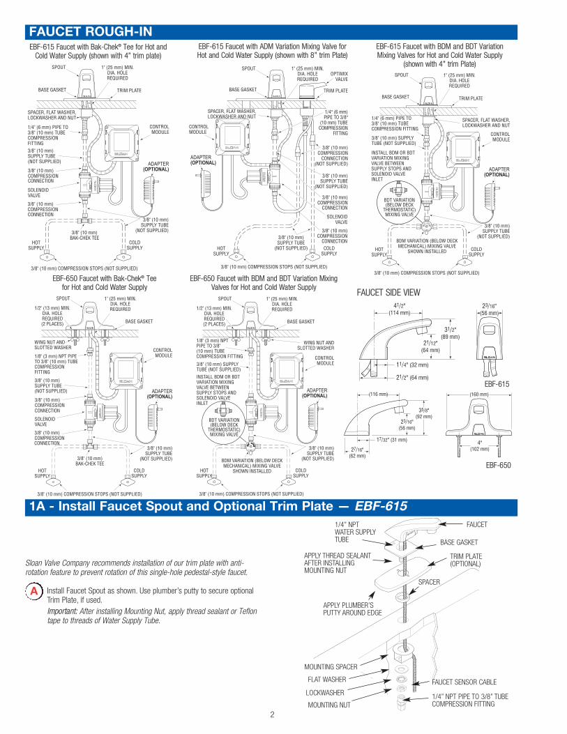
1B - Install Faucet Spout — EBF-650
A Install Faucet Spout as shown.Important: Apply thread sealant or Teflon tape to threads of WaterSupply Pipe Nipple.
Refer to the Installation Instructions included with the ETF-578-A Trim Platefor additional information about using an 8" Trim Plate with an EBF-650faucet.
FAUCET
1/8” NPT PIPE NIPPLE
BASE GASKET
FAUCET SENSOR CABLE
APPLY THREAD SEALANT
SLOTTED MOUNTINGWASHERS (2)WING NUTS (2)
1/8” NPT PIPE TO 3/8” TUBECOMPRESSION FITTING
2 - Install Solenoid Valve
A Install 3/8 inch (10 mm) supply tube (furnished by installer) betweenthe Compression Fittings on Spout and the top outlet of Solenoid Valve.
Flow direction of Solenoid Valve is indicated by an arrow on Valve Body.
3/8” (10 mm) SOLENOIDVALVE COMPRESSIONFITTING (TOP OUTLET)
3/8” (10 mm) SUPPLY TUBE(NOT SUPPLIED)
3/8” (10 mm)COMPRESSION FITTING
ModelEBF-615
Shown
3 - Connect Supply Line(s) from Supply Stop(s) to Solenoid Valve Inlet
Dual Line Hot and Cold Water Supply ApplicationsInstall a 3/8 inch (10 mm) copper supply tubebetween Bak-Chek® Compression Tee and hotand cold supply stops. (Supply tubes and stopsfurnished by installer.) Install a 3/8 inch (10 mm)copper supply tube between Bak-ChekCompression Tee and inlet side of SolenoidValve. Tighten Compression Fittings securely.
Note: Failure to install the Bak-Chek® Tee can result in a cross flow connection when the faucet is off and the supply stops are open. If pressure of the hot and cold water supply differ, hot water can migrate into the cold water supply or vice-versa. Most plumbing codes require that the Bak-Chek® be used to prevent this.
3/8” (10 mm) BAK-CHEK TEE USED
ON DUAL WATERSUPPLY
APPLICATIONSONLY
3/8” (10 mm)COMPRESSION
FITTING
3/8” (10 mm)SUPPLY TUBE
SOLENOIDVALVE
SUPPLYSTOP
A3/8” (10 mm)
COMPRESSIONFITTING
3/8” (10 mm)SUPPLY TUBE
SOLENOIDVALVE
SUPPLYSTOP
B Single Line Water Supply ApplicationsInstall a 3/8 inch (10 mm) copper supply tubebetween the supply stop and inlet side ofSolenoid Valve. (Supply tube and supply stopfurnished by installer.) Tighten CompressionFittings securely.
Important: Keep thread sealant out of your waterway and prevent componentpart damage! Do not use sealant on compression fittings. When threadsealant is used, do not apply it to the first two “starter” threads.Important: Flush dirt, debris, and sediment from the supply line(s).
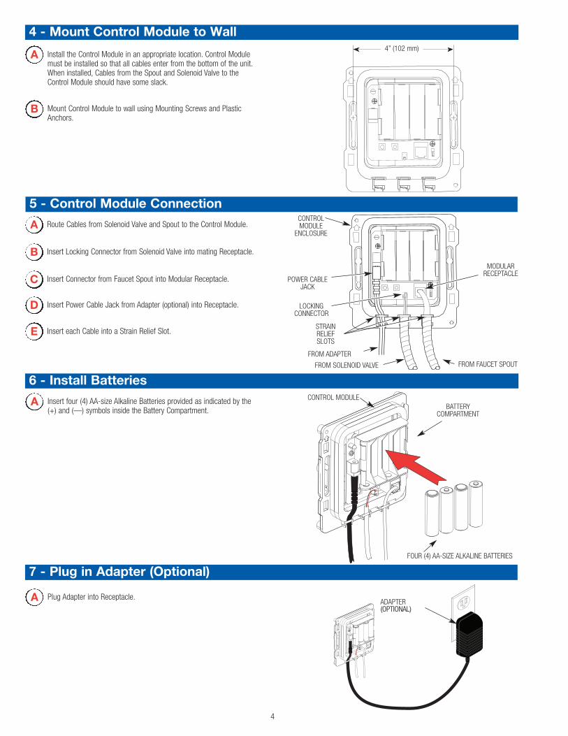
6 - Install Batteries
4
BATTERYCOMPARTMENT
CONTROL MODULEA Insert four (4) AA-size Alkaline Batteries provided as indicated by the(+) and (—) symbols inside the Battery Compartment.
4 - Mount Control Module to Wall
5 - Control Module Connection
B Insert Locking Connector from Solenoid Valve into mating Receptacle.
C Insert Connector from Faucet Spout into Modular Receptacle.
E Insert each Cable into a Strain Relief Slot.
B Mount Control Module to wall using Mounting Screws and PlasticAnchors.
A Install the Control Module in an appropriate location. Control Modulemust be installed so that all cables enter from the bottom of the unit.When installed, Cables from the Spout and Solenoid Valve to theControl Module should have some slack.
A Route Cables from Solenoid Valve and Spout to the Control Module.CONTROLMODULE
ENCLOSURE
FROM SOLENOID VALVE
FROM ADAPTER
STRAINRELIEFSLOTS
FROM FAUCET SPOUT
POWER CABLEJACK
4” (102 mm)
MODULARRECEPTACLE
LOCKINGCONNECTOR
FOUR (4) AA-SIZE ALKALINE BATTERIES
D Insert Power Cable Jack from Adapter (optional) into Receptacle.
7 - Plug in Adapter (Optional)
A Plug Adapter into Receptacle.ADAPTER(OPTIONAL)
Activate ( "dry fire") Faucet by placing hands in front of the Sensor. TheSolenoid Valve should “click.” Once hands are removed the SolenoidValve should click again. If this does not occur, refer to theTroubleshooting section of this instruction manual.Once "dry firing" segment is complete, remove spray head. Opensupply stop(s) then activateFaucet by placing hands infront of the Sensor. TheSolenoid Valve should"click" and water shouldflow from the Spout.
8 - Start-UpB Activate Faucet for 30 seconds by placing hands in front of the Sensor.
The Solenoid Valve should “click” and water should flow from theSpout. If this does not occur, refer to the Troubleshooting section of thisinstruction manual.
A
5
C Close supply stop(s) and reinstall Spray Head in Spout using the Keyprovided. Reopen supply stop(s), activate Faucet and check for leaks.
9 - Range Adjustment
A The Range Potentiometer is located in the Control Module.
Important: Range Potentiometer adjustment screw rotates only 3/4 of a turn;DO NOT over-rotate. Over-rotating will damage range adjustment screw.
CONTROL MODULE
RANGEPOTENTIOMETER
A SCREWDRIVER IS PROVIDED ONTHE INSIDE COVER OF THECONTROL MODULE FOR MAKINGRANGE ADJUSTMENTS
The OPTIMA Plus EBF-615 and EBF-650 Faucets are factory set tooperate when hands are placed 4 to 5 inches (102 to 127 mm) fromSensor. This range should be satisfactory for most installations. Ifrange adjustment is required, refer to the following range adjustmentprocedure.
B Cycle Faucet several times to assure that the Sensor will notinadvertently pick up reflection off the edge of the sink. If reflectionoccurs, adjust Range Potentiometer counterclockwise very slightly andagain cycle Faucet.Repeat adjustment procedure until desired range is achieved.
10 - Noise Reduction (NR) and Time Out (Mode) Jumper Settings
TIME OUT (MODE) JUMPER
NOISE REDUCTION (NR) JUMPER
For jumper settings, refer to Table below or label on cover of ControlModule along with the instructions in this Step.
Noise Reduction (NR) Setting• When operating the faucet on batteries alone, set the NR jumper to
bridge pins 1 and 2.• When operating the faucet using the plug-in adapter with battery
backup, bridge pins 2 and 3.
Time Out (Mode) SettingThe Faucet Time Out Setting determines the maximum time theFaucet will run upon continuous activation. This timing can bechanged to meet individual application requirements.Unless otherwise specified, Faucets leave the factory set with a 30second Time Out.
DESCRIPTION PINS1 2 3
NOISE REDUCTION (NR) SETTING
Normal Operation(Adapter w/Battery Backup Operation)NR Enabled(Battery Operation Only)
TIME OUT (MODE) SETTING
13.75 Second On Demand
30 Second On Demand
1. A continuousinvisible beam ofinfrared light isemitted from thesensor located onthe throat of thelavatory faucet.
2. As the user’shands enter thebeam’s effectiverange (beneaththe spray head),the beam isreflected backinto the sensor receiver and activates thesolenoid valve. Tempered water flows fromthe faucet into the sink until the hands areremoved from the beam or until the faucetreaches an automatic time out limit setting.
3 When hands aremoved awayfrom the sensor,the loss ofreflected lightinitiates anelectrical signalthat deactivates the solenoid valve, shuttingoff the water flow. The circuit thenautomatically resets and is ready for thenext user.
6
Battery Replacement Procedure (Water does not need to be turned off)
Care and CleaningDO NOT USE abrasive or chemical cleaners (including chlorine bleach)to clean faucets as they may dull the luster and attack the chrome orspecial decorative finishes. Use ONLY soap and water, then wipe drywith clean cloth or towel.While cleaning the bathroom tile, the faucet should be protected fromany splattering of cleaner. Acids and cleaning fluids will discolor orremove chrome plating.
The Sloan Optima Plus EBF-615 and EBF-650 faucets are furnishedwith four (4) AA-size alkaline batteries that provide up to two (2) yearsof operation (8000 cycles per month). A flashing LED signal indicatesthat battery power will be depleted within one (1) month.
C Reinstall Cover. Refer toStep 11.
B Remove old batteries andinsert four (4) new AA-sizeAlkaline Batteries asindicated by the (+) and(—) symbols inside theBattery Compartment.
A Remove Cover as follows:1. Remove the two (2)
Cover Screws.2. Press in the middle of
both sides. 3. Pull Cover straight out
from Control ModuleBase.
1
2
2
3
Operation
11 - Install Cover onto Control Module
A Install Cover over the Control Module making sure that all four (4)locking tabs snap into place. Secure using the two (2) screws provided.Cover can be installed in only one orientation.
CONTROL MODULE
CONTROL MODULECOVER
COVER SCREW (2)
LOCKING TAB (4)
Troubleshooting Guide
7
Solenoid Screen Filter Cleaning Procedure
A Turn off water supply at supply stop(s). Activate Faucet to relievesystem pressure.
B Remove Water Supply Line from Inlet Side of Solenoid Valve. RemoveCap, Water Line Fitting, Gasket, Filter Housing and Filter from SolenoidValve Housing.
C Slide Filter off Filter Housing. Clean Filter using fresh tap water only. Ifnecessary, use a small brush to clean. Use caution while cleaning toprevent damage to Filter.If any Filter components are damaged, replace as necessary. Examinethe Gasket for wear or damage; replace if necessary.
D Reinstall Filter on Filter Housing.Install Filter Housing, Gasket, Water Line Fitting and Cap onto SolenoidValve Housing.Tighten Cap securely.
FILTER
E Reinstall Water supply Line to Inlet Side of Solenoid Valve.
INLET SIDE OF SOLENOID VALVE HOUSING
FILTER HOUSING
WATER LINE FITTING
GASKET
CAP
When assistance is required, please contact your local SloanRepresentative or Sloan Valve Company Installation EngineeringDepartment at:
1-888-SLOAN-14 (1-888-756-2614)
1. PROBLEM: Sensor LED does not function (indicator light on sensor windowin faucet spout does not flash during initial 10 minute set-upmode).
CAUSE: There is no visible indicator light. Normal operation.SOLUTION: This is a normal operating feature of the faucet.
2. PROBLEM: Faucet does not deliver any water when Sensor is activated.INDICATOR: Solenoid valve produces audible “CLICK.”
CAUSE: Water supply stop(s) closed.SOLUTION: Open supply stop(s) completely.
INDICATOR: Solenoid valve DOES NOT produce an audible “CLICK.”CAUSE: Solenoid Lead is not properly connected to the Control Module.
SOLUTION: Disconnect and reconnect Solenoid Lead to the Control Module.CAUSE: No battery or Transformer (optional) power is being supplied to
Sensor.SOLUTION: Ensure that the batteries are installed properly. Check that the
orientation of each battery matches the positive (+) and negative(—) symbols shown on the bottom of the battery compartment.Reinsert the Batteries into the Control Module. Transformer(optional) is unplugged or wall receptacle has no power.
CAUSE: Sensor Cable is not properly connected to the Control Module.SOLUTION: Disconnect and reconnect Sensor Cable to the Control Module.
CAUSE: Sensor range is set at minimum distance.SOLUTION: Increase Sensor range. Refer to Step 9, Range Adjustment.
CAUSE: Control Module assembly is defective.SOLUTION: Replace Control Module assembly.
3. PROBLEM: Faucet delivers only a slow flow or dribble when Sensor isactivated.
CAUSE: Water supply stop(s) partially closed.SOLUTION: Open supply stop(s) completely.
CAUSE: Solenoid Filter is clogged.SOLUTION: Remove, clean and reinstall Filter. Refer to Solenoid Screen Filter
Cleaning Procedure on Page 6. Replace with new Solenoid FilterKit if necessary.
CAUSE: Aerator is clogged.SOLUTION: Remove, clean and reinstall Aerator.
4. PROBLEM: Faucet does not stop delivering water or continues to drip afteruser is no longer detected (automatic shut-off fails even whenbatteries are removed).
CAUSE: Solenoid Valve has been connected backwards.SOLUTION: Disconnect Solenoid Valve compression fittings at both the inlet
and outlet positions. The water should flow from inlet through theSolenoid Valve to the outlet according to the direction of thearrow shown on the side of the Solenoid Valve. Reconnect thecompression fittings in the correct orientation.
CAUSE: Solenoid Valve is dirty.SOLUTION: Backflush by reversing water flow (opposite to the direction
shown by the arrow on the side of the Solenoid Valve) throughthe Solenoid Valve. Reconnect the compression fittings in thecorrect orientation. Activate faucet.
CAUSE: Solenoid Valve Module is defective.SOLUTION: Replace Solenoid Valve Module.
5. PROBLEM: The water temperature is too hot or too cold on a faucetconnected to hot and cold supply lines with Bak-Chek Tee.
CAUSE: Supply stops are not adjusted properly.SOLUTION: Adjust supply stops.
NOTE: For some systems, a Thermostatic Mixing Valve may be required.
6. PROBLEM: The Red LED turns on in the control module (below deck).CAUSE: One (or more) of the batteries is “dead.”
SOLUTION: To ensure proper operation, insert four (4) new AA-size Alkalinebatteries. Check that the orientation of each battery matches thepositive (+) and negative (—) symbols shown on the bottom ofthe battery compartment. Reinsert Batteries into the ControlModule.
CONTROLMODULE
ENCLOSURE
FROM SOLENOID VALVE
FROM OPTIONALADAPTER
STRAINRELIEFSLOTS
FROM FAUCET SPOUT
POWER CABLEJACK
MODULARRECEPTACLE
LOCKINGCONNECTOR
SLOAN VALVE COMPANY • 10500 SEYMOUR AVENUE • FRANKLIN PARK, IL 60131Phone: 1-800-9-VALVE-9 or 1-847-671-4300 • Fax: 1-800-447-8329 or 1-847-671-4380
www.sloanvalve.comCopyright © 2010 SLOAN VALVE COMPANY Rev. 3 (08/10)The information contained in this document is subject to change without notice.
LLOO
DD
CC
HHOOTT
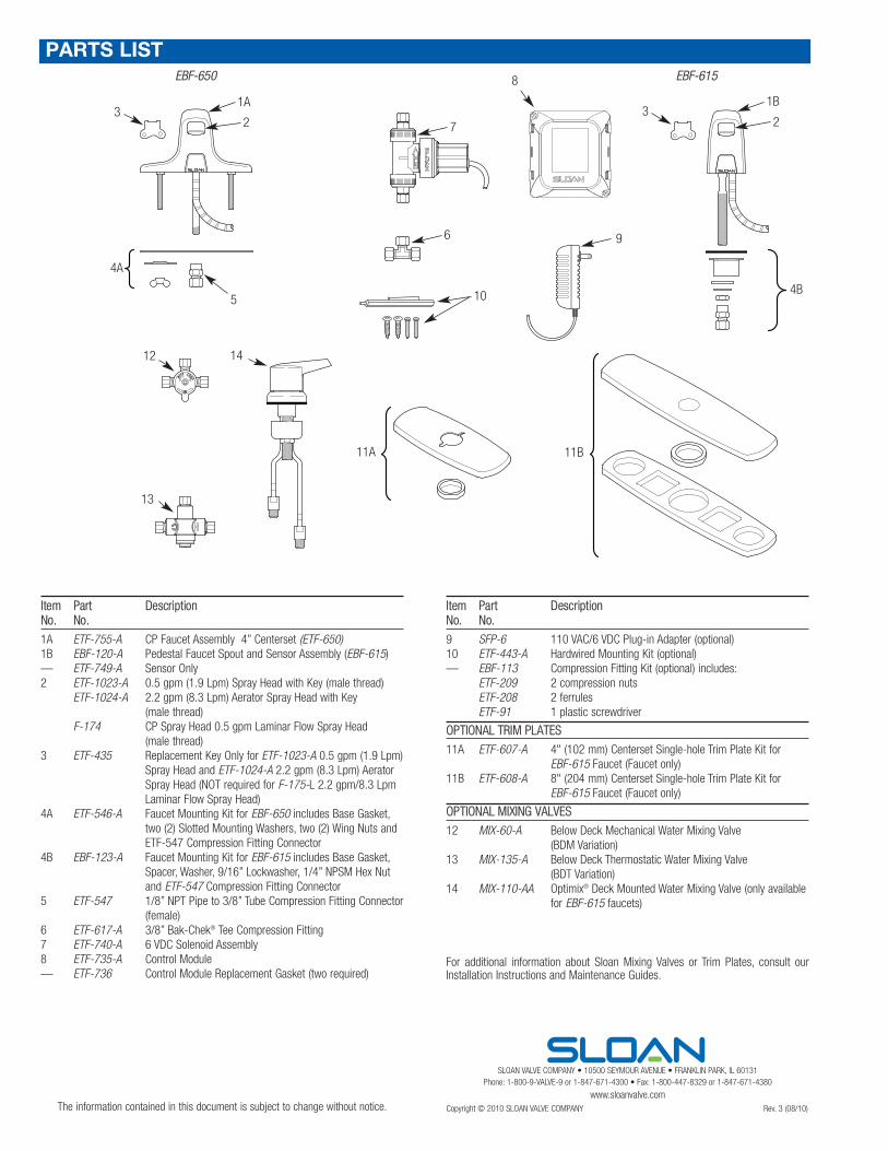
Item Part DescriptionNo. No.
1A ETF-755-A CP Faucet Assembly 4” Centerset (ETF-650)1B EBF-120-A Pedestal Faucet Spout and Sensor Assembly (EBF-615)— ETF-749-A Sensor Only2 ETF-1023-A 0.5 gpm (1.9 Lpm) Spray Head with Key (male thread)
ETF-1024-A 2.2 gpm (8.3 Lpm) Aerator Spray Head with Key(male thread)
F-174 CP Spray Head 0.5 gpm Laminar Flow Spray Head(male thread)
3 ETF-435 Replacement Key Only for ETF-1023-A 0.5 gpm (1.9 Lpm)Spray Head and ETF-1024-A 2.2 gpm (8.3 Lpm) AeratorSpray Head (NOT required for F-175-L 2.2 gpm/8.3 LpmLaminar Flow Spray Head)
4A ETF-546-A Faucet Mounting Kit for EBF-650 includes Base Gasket,two (2) Slotted Mounting Washers, two (2) Wing Nuts andETF-547 Compression Fitting Connector
4B EBF-123-A Faucet Mounting Kit for EBF-615 includes Base Gasket,Spacer, Washer, 9/16” Lockwasher, 1/4” NPSM Hex Nutand ETF-547 Compression Fitting Connector
5 ETF-547 1/8” NPT Pipe to 3/8” Tube Compression Fitting Connector(female)
6 ETF-617-A 3/8” Bak-Chek® Tee Compression Fitting7 ETF-740-A 6 VDC Solenoid Assembly8 ETF-735-A Control Module— ETF-736 Control Module Replacement Gasket (two required)
LO
D
C
HOT
EBF-615
1A
4A
EBF-650
23
5
1B
2
6
11A 11B
12
13
14
3
4B
7
PARTS LIST8
9
10
Item Part DescriptionNo. No.
9 SFP-6 110 VAC/6 VDC Plug-in Adapter (optional)10 ETF-443-A Hardwired Mounting Kit (optional)— EBF-113 Compression Fitting Kit (optional) includes:
ETF-209 2 compression nutsETF-208 2 ferrulesETF-91 1 plastic screwdriver
OPTIONAL TRIM PLATES
11A ETF-607-A 4" (102 mm) Centerset Single-hole Trim Plate Kit forEBF-615 Faucet (Faucet only)
11B ETF-608-A 8" (204 mm) Centerset Single-hole Trim Plate Kit forEBF-615 Faucet (Faucet only)
OPTIONAL MIXING VALVES
12 MIX-60-A Below Deck Mechanical Water Mixing Valve(BDM Variation)
13 MIX-135-A Below Deck Thermostatic Water Mixing Valve(BDT Variation)
14 MIX-110-AA Optimix® Deck Mounted Water Mixing Valve (only availablefor EBF-615 faucets)
For additional information about Sloan Mixing Valves or Trim Plates, consult ourInstallation Instructions and Maintenance Guides.