Embed Size (px)
Citation preview
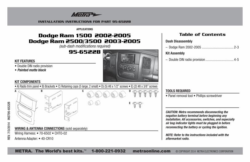
APPLICATIONS
METRA. The World’s best kits.™ metraonline.com1-800-221-0932 © COPYRIGHT 2014 METRA ELECTRONICS CORPORATION
REV.
7/3
/201
4 I
NST9
5-65
22B
CAUTION: Metra recommends disconnecting the negative battery terminal before beginning any installation. All accessories, switches, and especially air bag indicator lights must be plugged in before reconnecting the battery or cycling the ignition.
NOTE: Refer to the instructions included with the aftermarket radio.
Table of Contents
INSTALLATION INSTRUCTIONS FOR PART 95-6522B
• Double DIN radio provision• Painted matte black
• A) Radio trim panel • B) Brackets • C) Retaining caps (5 large, 2 small) • D) (5) #8 x 1/2” screws • E) (2) #8 x 3/8” screws
KIT FEATURES
KIT COMPONENTS
WIRING & ANTENNA CONNECTIONS (sold separately)Wiring Harness: • 70-6502 • CHTO-02
Antenna Adapter: • 40-CR10
• Panel removal tool • Phillips screwdriverTOOLS REQUIRED
Dodge Ram 1500 2002-2005Dodge Ram 2500/3500 2003-2005
(sub-dash modifications required)
95-6522B
A B C D
E
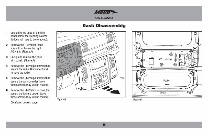
Dash Disassembly
– Dodge Ram 2002-2005 ....................................2-3
Kit Assembly
– Double DIN radio provision ................................4-5
95-6522B
1. Unclip the top edge of the trim panel below the steering column (it does not have to be removed).
2. Remove the (1) Phillips-head screw from below the right A/C vent. (Figure A)
3. Unclip and remove the dash trim panel. (Figure A)
4. Remove the (4) Philips screws that secure the radio. Disconnect and remove the radio.
5. Remove the (4) Philips screws that secure the a/c controller (save these screws they will be reused).
6. Remove the (4) Phillips screws that secure the factory pocket (save these screws they will be reused).
Continued on next page
Dash Disassembly
(Figure A) (Figure B)
2
A/C controller
95-6522B
Dash Disassembly
(Figure C)
(Figure D)
3
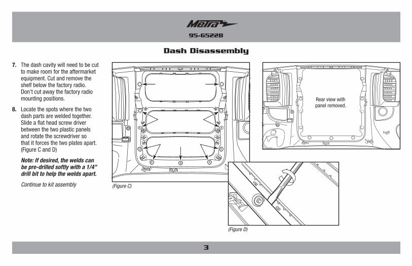
7. The dash cavity will need to be cut to make room for the aftermarket equipment. Cut and remove the shelf below the factory radio. Don’t cut away the factory radio mounting positions.
8. Locate the spots where the two dash parts are welded together. Slide a flat head screw driver between the two plastic panels and rotate the screwdriver so that it forces the two plates apart. (Figure C and D)
Note: If desired, the welds can be pre-drilled softly with a 1/4” drill bit to help the welds apart.
Continue to kit assembly
Rear view with panel removed.
95-6522B
Kit Assembly
(Figure A) (Figure B)
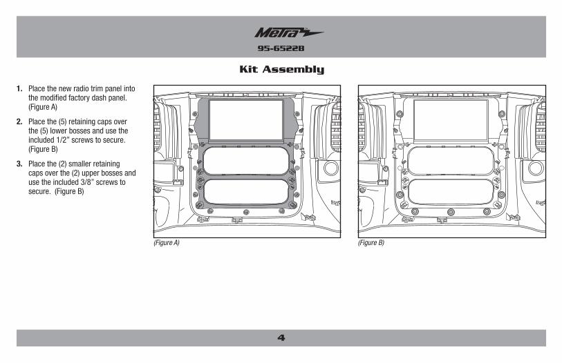
1. Place the new radio trim panel into the modified factory dash panel. (Figure A)
2. Place the (5) retaining caps over the (5) lower bosses and use the included 1/2” screws to secure. (Figure B)
3. Place the (2) smaller retaining caps over the (2) upper bosses and use the included 3/8” screws to secure. (Figure B)
4
95-6522B
Kit Assembly
(Figure A)
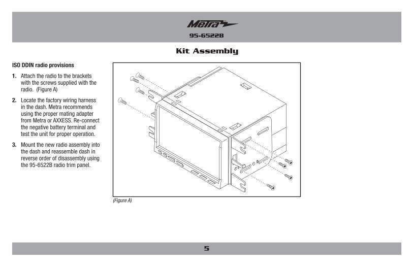
ISO DDIN radio provisions
1. Attach the radio to the brackets with the screws supplied with the radio. (Figure A)
2. Locate the factory wiring harness in the dash. Metra recommends using the proper mating adapter from Metra or AXXESS. Re-connect the negative battery terminal and test the unit for proper operation.
3. Mount the new radio assembly into the dash and reassemble dash in reverse order of disassembly using the 95-6522B radio trim panel.
5
Notes
6
Notes
7
METRA. The World’s best kits.™ metraonline.com1-800-221-0932 © COPYRIGHT 2014 METRA ELECTRONICS CORPORATION
REV.
7/3
/201
4 I
NST9
5-65
22B
KNOWLEDGE IS POWEREnhance your installation and fabrication skills by enrolling in the most recognized and respected mobile electronics school in our industry.Log onto www.installerinstitute.com or call 800-354-6782 for more information and take steps toward a better tomorrow.
Metra recommends MECP certified technicians
INSTALLATION INSTRUCTIONS FOR PART 95-6522B
INSTRUCCIONES DE INSTALACIÓN PARA LA PIEZA 95-6522B
AplicAciones
METRA. The World’s best kits.™ metraonline.com1-800-221-0932 © COPYRIGHT 2014 METRA ELECTRONICS CORPORATION
REV.
7/3
/201
4 I
NST9
5-65
22B
PRECAUCIÓN: Metra recomienda desconectar el terminal negativo de la batería antes de comenzar cualquier instalación. Todos los accesorios, interruptores y, especialmente, las luces indicadoras de airbag deben estar enchufados antes de volver a conectar la batería o comenzar el ciclo de ignición.
Nota: Remítase a las instrucciones incluidas con el radio de posventa.
Indice
• Herramienta para quitar paneles • Destornillador Phillips
HerrAmientAs requeridAs
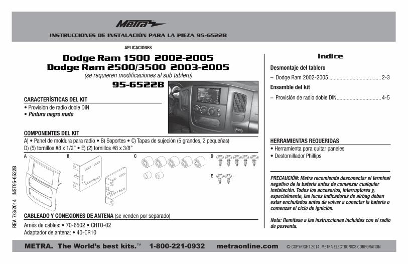
• Provisión de radio doble DIN• Pintura negro mate
A) • Panel de moldura para radio • B) Soportes • C) Tapas de sujeción (5 grandes, 2 pequeñas) D) (5) tornillos #8 x 1/2” • E) (2) tornillos #8 x 3/8”
cArActerísticAs del kit
componentes del kit
cABleAdo Y coneXiones de AntenA (se venden por separado)
Arnés de cables: • 70-6502 • CHTO-02Adaptador de antena: • 40-CR10
Dodge Ram 1500 2002-2005Dodge Ram 2500/3500 2003-2005
(se requieren modificaciones al sub tablero)
95-6522B
A B C D
E
Desmontaje del tablero
– Dodge Ram 2002-2005 ....................................2-3
Ensamble del kit
– Provisión de radio doble DIN ...............................4-5
95-6522B
Desmontaje del tablero
2
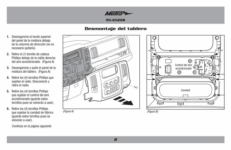
1. Desenganche el borde superior del panel de la moldura debajo de la columna de dirección (no es necesario quitarlo).
2. Retire el (1) tornillo de cabeza Phillips debajo de la rejilla derecha del aire acondicionado. (Figura A)
3. Desenganche y quite el panel de la moldura del tablero. (Figura A)
4. Retire los (4) tornillos Phillips que sujetan el radio. Desconecte y retire el radio.
5. Retire los (4) tornillos Phillips que sujetan el control del aire acondicionado (guarde estos tornillos pues se volverán a usar).
6. Retire los (4) tornillos Phillips que sujetan la cavidad de fábrica (guarde estos tornillos pues se volverán a usar).
Continúa en la página siguiente
(Figura A) (Figura B)
Control del aire acondicionado
Cavidad
95-6522B
Desmontaje del tablero
3
(Figura C)
(Figura D)
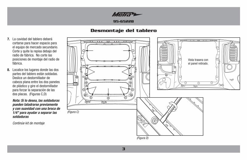
7. La cavidad del tablero deberá cortarse para hacer espacio para el equipo de mercado secundario. Corte y quite la repisa debajo del radio de fábrica. No corte las posiciones de montaje del radio de fábrica.
8. Localice los lugares donde las dos partes del tablero están soldadas. Deslice un destornillador de cabeza plana entre los dos paneles de plástico y gire el destornillador para forzar la separación de las dos placas. (Figuras C,D)
Nota: Si lo desea, las soldaduras pueden taladrarse previamente y con suavidad con una broca de 1/4” para ayudar a separar las soldaduras
Continúe kit de montaje
Vista trasera con el panel retirado.
95-6522B
Ensamble del kit
(Figura A) (Figura B)
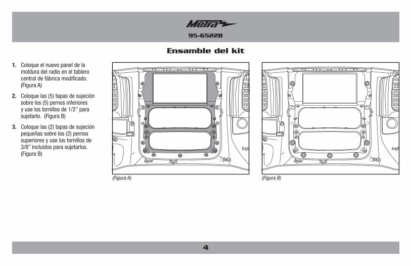
1. Coloque el nuevo panel de la moldura del radio en el tablero central de fábrica modificado. (Figura A)
2. Coloque las (5) tapas de sujeción sobre los (5) pernos inferiores y use los tornillos de 1/2” para sujetarlo. (Figura B)
3. Coloque las (2) tapas de sujeción pequeñas sobre los (2) pernos superiores y use los tornillos de 3/8” incluidos para sujetarlos. (Figura B)
4
95-6522B
Ensamble del kit
5
(Figure A)
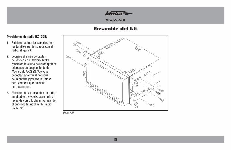
Provisiones de radio ISO DDIN
1. Sujete el radio a los soportes con los tornillos suministrados con el radio. (Figura A)
2. Localice el arnés de cables de fábrica en el tablero. Metra recomienda el uso de un adaptador adecuado de acoplamiento de Metra o de AXXESS. Vuelva a conectar la terminal negativa de la batería y pruebe la unidad para verificar que funcione correctamente.
3. Monte el nuevo ensamble de radio en el tablero y vuelva a armarlo al revés de como lo desarmó, usando el panel de la moldura del radio 95-6522B.

95-6522B
6
95-6522B
7
INSTRUCCIONES DE INSTALACIÓN PARA LA PIEZA 95-6522B
METRA. The World’s best kits.™ metraonline.com1-800-221-0932 © COPYRIGHT 2014 METRA ELECTRONICS CORPORATION
REV.
7/3
/201
4 I
NST9
5-65
22B
KNOWLEDGE IS POWEREnhance your installation and fabrication skills by enrolling in the most recognized and respected mobile electronics school in our industry.Log onto www.installerinstitute.com or call 800-354-6782 for more information and take steps toward a better tomorrow.
Metra recomienda técnicos con certificación del Programa de Certificación en Electrónica Móvil (Mobile Electronics Certification Program, MECP).
EL CONOCIMIENTO ES PODERMejore sus habilidades de instalación y fabricación inscribiéndose en la escuela de dispositivos electrónicos móviles más reconocida y respetada de nuestra industria. Regístrese en www.installerinstitute.com o llame al 800-354-6782 para obtener más información y avance hacia un futuro mejor.