Embed Size (px)
Citation preview

"
Introduction
Installation Instructions for
Removable Windload Postfor Impact Rated doors
Contents
,'~~,. ...•.
.',(. \11)" . Lj~l'1Lt" rvY.
, i
The purpose of these instructions is to guide the installer in equipping a garage door with a removable postor posts for use against high windload conditions. Under normal operations, the removable post is not to beengaged. The horizontal struts provide the structural strength for normal operation and wind conditions. The
principal purpose ofthe removable post is to provide an additional structural member between the concretefloor and the header support.
ImportantThe addition of the Windload Post to an existing garage door will increase the wind load capacity of the door
assembly as shown on the Windload drawing. However, it is necessary that the garage building structure alsobe capable of withstanding this wind load pressure. The ultimate strength ofthe entire system is a function ofthe garage door reinforcement, door jamb attachment and building structure.
Warnings & Safety Information 2
Key Drawing 3Windload Post Installation .4-5
Windload Post Operation 6Windload Post Labels 7Windload Post Parts 8
This installation manual provides the trained door system technician information required to install, troubleshoot and maintain an Impact Rated Windload Post installation.
READ COMPLETE INSTRUCTIONS BEFORE INSTALLING.
Some installation tasks listed in this document are found in other documents.
Please refer to the appropriate document(s) as directed;PN:409783 Jamb Installation Detail
Windload Drawing accompanying this unit
410833-0001 04/14/2009 www.overheaddoor.com ©2009 Overhead Door Corporation

SAFETY INFORMATIONOVERVIEW OF POTENTIAL HAZARDS
READ THIS SAFETY INFORMATIONOverhead doors are large, heavy objects that move with the help of springs under high tension and electric motors. Since moving objects, springs under tension, and
electric motors can cause injuries, your safety and the safety of others depend on you reading the information in this manual. If you have questions or do not understandthe information presented, call your nearest trained door system technician.
In this section, and those that follow, the words Danger, Warning, and Caution are used to emphasize important safety information. The word:
A DANGER indicates an imminently hazardous situation which, if not avoided, will result in death or serious injury.
A WARNING indicates a potentially hazardous situation which, if not avoided, could result in death or serious injury.
A CAUTION indicates a potentially hazardous situation which, if not avoided, may result in injury or property damage.
The word NOTE is used to indicate important steps to be followed or important considerations.
IMPORTANT SAFETY INSTRUCTIONSREAD AND FOllOW All INSTRUCTIONS
SAVE THESE INSTRUCTIONS
, Do NOT allow children to play with the Door Operator.Could result in Death
or Serious Injury I Do NOT operate a Door that jams or one that has a broken spring.
When replacing cover, make sure wires are NOT pinching or near moving parts.Could result in Death'
or Serious Injury I Operator must be fully grounded.
Potential Hazard
MOVING DOOR
~ELECTRICALSHOCK
Effect
it. WARNING
it. WARNING
Keep people clear of opening while Door is moving.
Turn OFF power before removing operator cover.
Prevention
••~
~~~••••
HIGH SPRINGTENSION
it. WARNING
Could result in Death
or Serious Injury
Do NOT try to remove, install, repair or adjust springs or anything to which door spring parts are fastened, such as,wood blocks, steel brackets, cables or other like items.
Installations, repairs and adjustments must be done by a trained door system technician using proper tools andinstructions.
2 410833-0001 04/14/2009 www.overheaddoor.com ©2009 Overhead Door Corporation

~~ BOTTOM STRUT CABLE(not required on all doors)
For storage or when not in use, post should be mounted securely on wall(using scab brackets and provided track bolts and wing nuts) as close to dooras possible. Wall mount hardware provided.3 410833-0001 04/14/2009
Key DrawingThe Impact Rated Wind load Post is designed to be installed on any sectionalgarage door at the center hinge locations. Certain Thermacore® doors mayallow for the post to be installed independent of center hinges. Fbr two ormore posts, each post must be evenly spaced across the door width and/orcentered on a stile with a hinge. Refer to the Windload Drawing for locations.
Use the same installation procedure for one, two, or three post assemblies.
NOTE: Impact Rated Windload Post will not work on doors with strutstaller than 2-1/4".
NOTE: Doors must have at least one (1) strut installed per section.Struts can be a maximum of 2-1/4" tall.
. ,lA,~b 0. r~· ~lq
CLEVIS PI~ " fC4\17t5
©2009 OverheadDoorCorporation
FLOOR PLATE
www.overheaddoor.com
DOOR /BOTTOM
STRUT
POST BRACKET
POST MOUNTEDTO DOOR AT
NON HINGE LOCATION
BOTTOM STRUTCABLE STORAGE
(not required on all doors)
([fJ
POST LABEL
~/SCAB /
BRACKET
HASP
SCAB
BRACKET
Windload Post Installation
HASPLOCK BAR
1/2" DIAHOLES
Fig4
POST
· :'; ~
, '~NW~:/~l(71(0
STEP 5
Remove the post assembly. With the floor plate stillin place, mark the location of the four mountingholes and the two holes for the hasp lock bars.Remove the floor plate and drill four 3/16" diametermounting holes, 1" deep; and two W' diameter lockbar holes, 2" deep.Attach the floor plate to the floor usin1gthe fouranchor bolts (supplied).
STEP 4
• Raise the post assembly enough to slide the floorplate underneath.Align the two Vz" holes in the floor plate with thelock bars of the hasps on the sides of the postassembly. See Figure 4.
Fig 2b
POST
Fig 2a
DOOR PANEL
~
STEP 3
• With the door in the closed position, place the postassembly against the door struts, but no more than2 - 1/4" from door panel, resting on the floor andaligned with hinges as shown in Figure 3.Ensure that the post assembly is plumb.
STEP 2 {continued}• Attach two Post Brackets to each hinge on the door
s'~ilehinges that will receive the wind load post asshown in Figure 2a.OR
Attach two Post Brackets to each section joint ofthe door (in the location shown on the WindloadDrawing that will receive the wind load post) asshown in Figure 2b.
REMOVEBOLT
or
CLEVIS PIN
Fig 1
STEP 2
Determine the location of the Impact RatedWind load Post installation ensuring that it alignson a door stile with hinges. Refer to the WindloadDrawing for quantity of posts and post locations.For two or more posts, each post must be evenlyspaced across the door width and centered on astile with a hinge. (Some doors may not requireposts centered on a stile with a hinge.) Use thesame installation procedure for one, two, or threepost assemblies.
STEP 1
• Close the garage door.Unplug the garage door opener (if equipped).Detach the opener drawbar by removing the boltor pin that attaches it to the bracket on the door asshown in Figure 1.
Fig 3
4 410833-0001 04/14/2009 www.overheaddoor.com ©2009 Overhead Door Corporation

HEADER SUPPORTBRACKET
.'.'
Fig9
\
SPRINGTYPECOTTERPIN
HASP LOCKBAR
Fig 10
WING SCAB
W" ~V"""'~c""" pOST "" 0"
0000
The Impact Rated Wind load Post installation iscomplete. Remove the post and store in a safe andsecure location near door until needed.
STEP 10
• Apply Instruction Labels (shown on page 7) todoor section and to the Impact Rated Wind loadPost. Refer to Key Drawing on page 3 of theseinstructions for approximate locations.
Refer to the Windload Drawing to determine if this
installation requires a bottom cable.
Route the Strut Cable between the door and the
bottom strut leaving the cable eyes near the hasp.Insert the clevis pin into the top eye of the hasp,through both Strut Cable eyes and into the bottomeye of the hasp. See Figure 10.
Insert the sp,ing type cotte' pin into the clev~~,
BOTTOM r{A.f~7l8CABLE
WINDLOAD POSTS WITH BOTTOM CABLE.
STEP 9
Mount both scab brackets equally spaced to theback of the Windload Post using bolt and wing nut.See Figure 9.
HEADERLINK
FigS
Fig 7
STORAGE
STEP 8
Install post storage mounting bolts (provided) towall near the door on a structurally sound woodsubstrate capable of supporting the post.
NOTE: Return the post to the installed position if youremoved the post to mount the Header Support Bracket.
STEP 7
Insert the cables (three for 7' high door and four for
8' high door) through the 7/16" diameter holes inthe post.
• Assemble the ends of the cables as shown using
clevis pin and cotter pin. See Figure 8.
STEP 6 (continued)
NOTE: The header support bracket should be attachedto a structurally sound wood substrate capable ofwithstanding the post load stated on the WindloadDrawing (Also see Drawing #409783 for wood jambinstallation details) .
HASPLOCKBAR
Fig6Rotate the header links and header support
bracket horizontally towards the header. Attachthe header support bracket to the header withthe four 5/16" x 1 3,4" lag screws (provided). SeeFigure 7.
Fig 5POST
Return post to its original position on door.Engage the lock bars of the hasps with the floorplate. See Figure 6.
SPRINGTYPE WASHER
C~m/·----~I:~WASHER I - ,,..-.~~CP ~.JHEADER CP CLEVIS PINLINK
STEP 6
Attach the two header links to the top of the post
using the clevis pin, washers, and spring typecotter pins.Attach the header support bracket to the otherend of the header links with the clevis pin, washer,
and spring type cotter pin.
5 410833-0001 04/14/2009 www.overheaddoor.com ©2009 Overhead Door Corporation
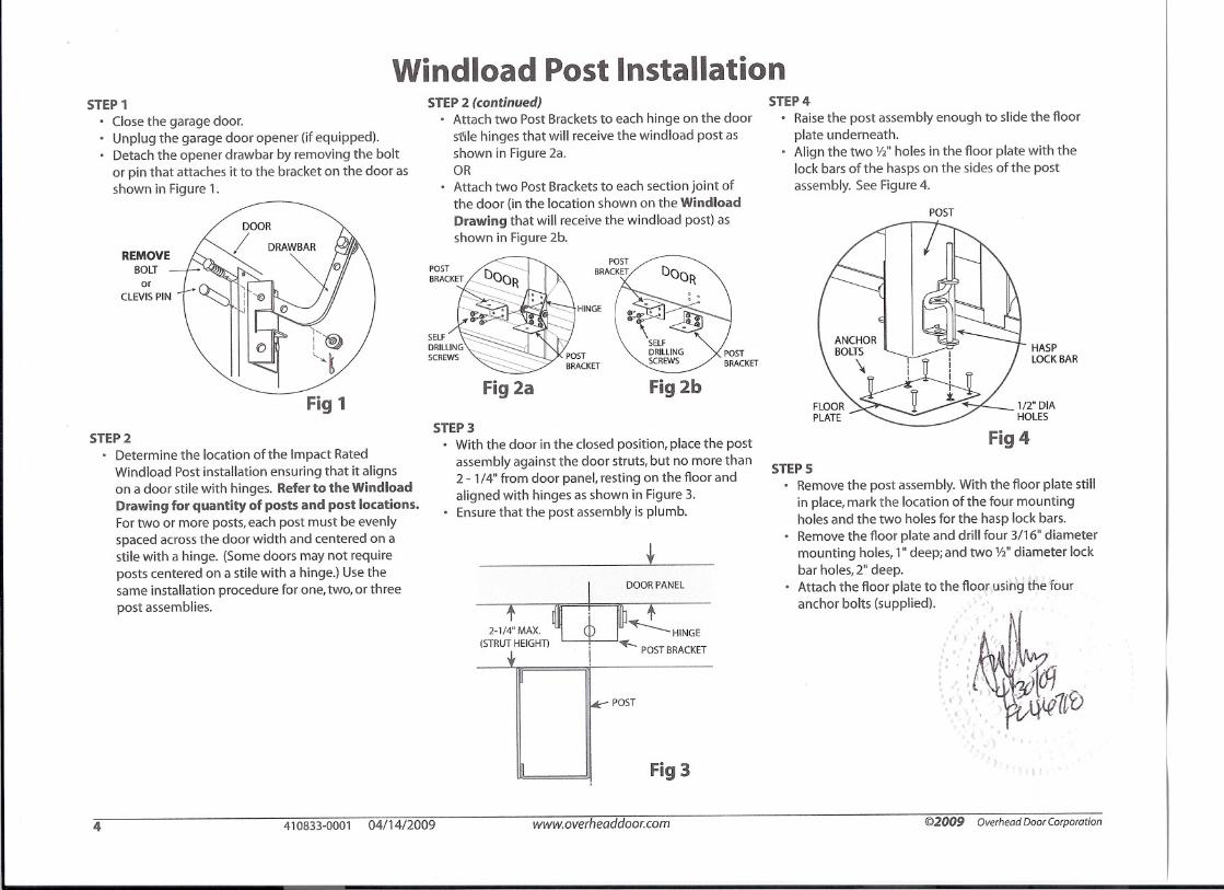
Windload Post Operation
Reverse these steps to remove the Impact Rated Windload Post.
~. ";I~A':' -.;?!i<J _
':. /, .~~7tb, ) ,
CLEVIS PIN .: 'HEADER SUPPORT
'~ .' • BRACKET
Fig 12
BOTTOM STRUT CABLE
(not required on all doors)
POST
Fig 11
REMOVE
BOLT
or
CLEVIS PIN
A CAUTION: Do NOT attempt to operate garage doorwhile the Impact Rated Wind load Post is attached fagarage door.
STEP 2
• With the door in the closed position, attach the header linksto the header support bracket using the spring type cotterpin and washers (supplied).
• Place the post bottom on the floor plate, slide the hasp lockbars into the floor plate holes, and secure hasps.Attach the cable assemblies (three for 7' high door and fourfor 8' high door) to the post brackets using clevis pins andspring type cotter pins.
Doors with Bottom Strut Cable onlyRoute the Bottom Strut Cable between the bottom strut andthe door.
Insert the clevis pin into the top eye of the hasp,through both Strut Cable eyes and into the bottomeye of the hasp.Insert the spring type cotter pin into the clevis pin.
STEP 1
Close the garage door.Unplug the garage door opener (if equipped).
• Detach the opener drawbar by removing the bolt or pin thatattaches it to the bracket on the door as shown in
Figure 11.
6 410833-0001 04/14/2009 www.overheaddoor.com ©2009 Overhead Door Corporation

Post label
Windload Post labels
.,
Door label
,
I ,
·>·,N'>~I~09f&~{qltb
If :.sr BaTT OM ST nurCABLE ASSEMBLYDEPEIJ::m;G Ot.\'I\IJOLO.'O
REOlJiRE.'.tFJ; T$
~~.'~~w~·"JW~~ ~~the O'r!I'/IU/ ,Y/"C0 192/
Removable Windload PostIntroductiun
Your garage door is equipped with a Removable I)ost orposts for llse against high wind load conditions. Undernonnal operations, the Rcmovable Post is nut to heengaged. The principal ofthe Rcmovable Post is toprovide an additional structural member betwecn theconcrete floor and the header support.
The Removable Windlo"d Post shollid he eng"gedfor willd spced in cxccss of 75 mph.
IIi~h Windload I'ren,,,.,,tion
I. Close thc garage door.
2. Unplug the garage door opener (if equipped) andremove pin that attaches opener drawbar arm togarage door.
3. Lock both lelt and right hand slide locks (if supplied).
4. Attach the RClllov"ble Post according to the InstructionLabel attached to the garage door section.
CAUTION: Garage door is now in a lockedposition. Do Not attempt to operate.
3/11/05410410-0002
POSTI\ss~.tm.Y
rlOOR PLATE
POST lUJK Hb"CEHSUPPOAiHR~CK~r
CHITERSTIlE
u.STRocnorlLMH1 S
srnur
HINGE Cf\~nE"SSE/.WLY
~~.~~~w~,.'~~ ~~tlte (Hr!JU'Uf.,YI/IC0 19.21
Removable Windload Post
Illtroduction
Y ollr garage door is equipped with a Remov"ble Post or posts!t,r use against high windload conditions. Under normaloperations, the Removable Post is not to he engaged. Thehorizontal struts (see figure to lelt) provide the stmctural strengtht<,r normal operation and wind conditions. The principal of theRemuvable I'ost is to provide an additional stmctural memberbetween the concrete floor and the header supp0I1.
The Rcmov"blc Windload Post should bc engaged 1'01'
wind specd in excess of 75 mph.
Hi~h Windload Preparation
I. Close the garage door.
2. Unplug the garage door opener (if cquippcd) andremovc pin that attachcs opencr drawbar arm togarage door.
3. Lock both left and right band slide locks (if supplied).
4. Engage the header links to the header support bracket clevispins. (Refer to illustrations for reeommended cngagementsteps).
5. Thread thc cable assemblies through the post and attach to thehingc brackets using thc clevis bolts and cottcr pins that arcprovided. Ifa bottom strut cable is required, loopcable around bottom strut and attach to hasp loek bar with
clevis pin and cotter pin provided.
6. Epgage the hasp lock bars into the floor plate and securc.
7. For doors with more than one Removable Post, repeat steps 4
through 6 on the remaining posts.
CAUTION: Garage door is now in a locked position.Do Not attempt to operate.
8. To return to standard door operation, disengage theRcmov"ble Post hasp lock bars at the floor plate and store thelock bars in thc up position. Rcmovc thc cable asscmblicsfrom the hinge brackets. Store thc cable assemblies withthc Removable Post as shown on Page 3 of installationinstruction 410408-000] .
410410-0000Overhead Door Corporation Lewisville, TX
4/7/05410410-0001
7 410833-0001 04/14/2009 www.overheaddoor.com ©2009 Overhead Door Corporation

Windload Post Parts
OCP -:DQ)Cable Assy Windload Residential409347-0001
Header Link, Vertical Post408879-0001
~
RrmQ""bl.Wlltdlo"dPoSIml.., •.."•••4••••,
~;~~
--'-~'---'_._'-"'.~_ •._ ~~•.•.__, _._·on·" .••.•.•..-.--- ..-..- ....-...-----~~._._.-~,~;::.-::..;:o::.:;:~''''~',.•~'':.,:'''-:-:::.:..~=;..";:.:::.:;.;,;"~':""'-•.,, •.•.,.~:;, ••
flY l{~7~Instr Instl Post Impact-rF.lted410833-0001
'4J~lJ."-tP'
~~
"'..uU.ltt...,..,p
Label Wind load Post,Universal410410-0000
I PART NUMBERPART DESCRIPTION QNTY
UNIT I
MEASURE410405-0001
Kit Fastener, Impact Rated Windload Post1EA
408876-0001
Header Support 1EA
408879-0001
Header Link 2EA
409437-0003
Post Bracket 8EA
410406-0001
Windload Post 4EA
409347-0001
Cable Assy Windload Residential 1EA
409331-0002
Floor Plate 1EA
405964-0001
Scab Angle Bracket 2EA
410833-0001
Instr Instl Post Impact-rated '1EA
41 041 0-0000
Label Wind load Post, Universal 1\ 1,EA
~.~\~u.
o
oFloor Plate, 4-1/4" Long 10409331-0002
oo
oo
....
Post41 0406-0001
4-1/4"
~~/4'
010
Header Support, Vertical Post408876-0001
Post Bracket ~409437-0003 =~
Scab Angle Bracket405964-0001
410405-0001, Kit Fastener ContentsPART
PART DESCRIPTION QNTYUNIT!
NUMBERMEASURE
608308-0001
Wing Nut, 1/4-20 2EA
608304-0001
Masonry Anchor, 3/16" X 1-3/4" L4EA
608070-0001
Cotter Pin,1.875" L 7EA
608069-0004
Clevis Pin,.250" Dia X 5" L 4EA
608069-0002
Clevis Pin,375" Dia X 3.50" L3EA
605879-0001
Self Drilling Screw,1/4-20 X 3/4" L16EA
605574-0001
Lag Screw,5/16" X 1 -3/4" L6EA
080302-3240
FlatWasher,7/16" X 1-1/4" OD2EA
080019-0003
60LT,Track,1/4-20 Xl" L 2EA
608761-0001
T-Plug,.512 2EA
8 410833-0001 04/14/2009 www.overheaddoor.com ©2009 Overhead Door Corporation