Embed Size (px)
Citation preview
INSTALLATION INSTRUCTIONS
ISCI SPYDER HANDBRAKE SPY-HB-RT-13 Great care has gone into providing complete and thorough installation instructions. Use the torque values listed on the Assembly Drawing when tightening all fasteners. Use the supplied Loctite on all fasteners that do not have any mechanical locking device. See terms and conditions located at the end of this document.
NOTE: THE PHOTOS IN THESE INSTRUCTIONS ARE FROM A 2010 RT.
DIFFERENCES WILL BE NOTED!!
1. Ensure that all parts and the proper quantities of parts that are listed in the Parts List on the Assembly Drawing are in the package. Some of these items are pre-assembled.
2. Refer to Spyder Shop Manual and remove all side body panels, Middle, Upper and Lower from the right side and the Central Panel.
3. Remove two Lateral Support Screws from the top of the Driver’s Footrest Support.
!
!!
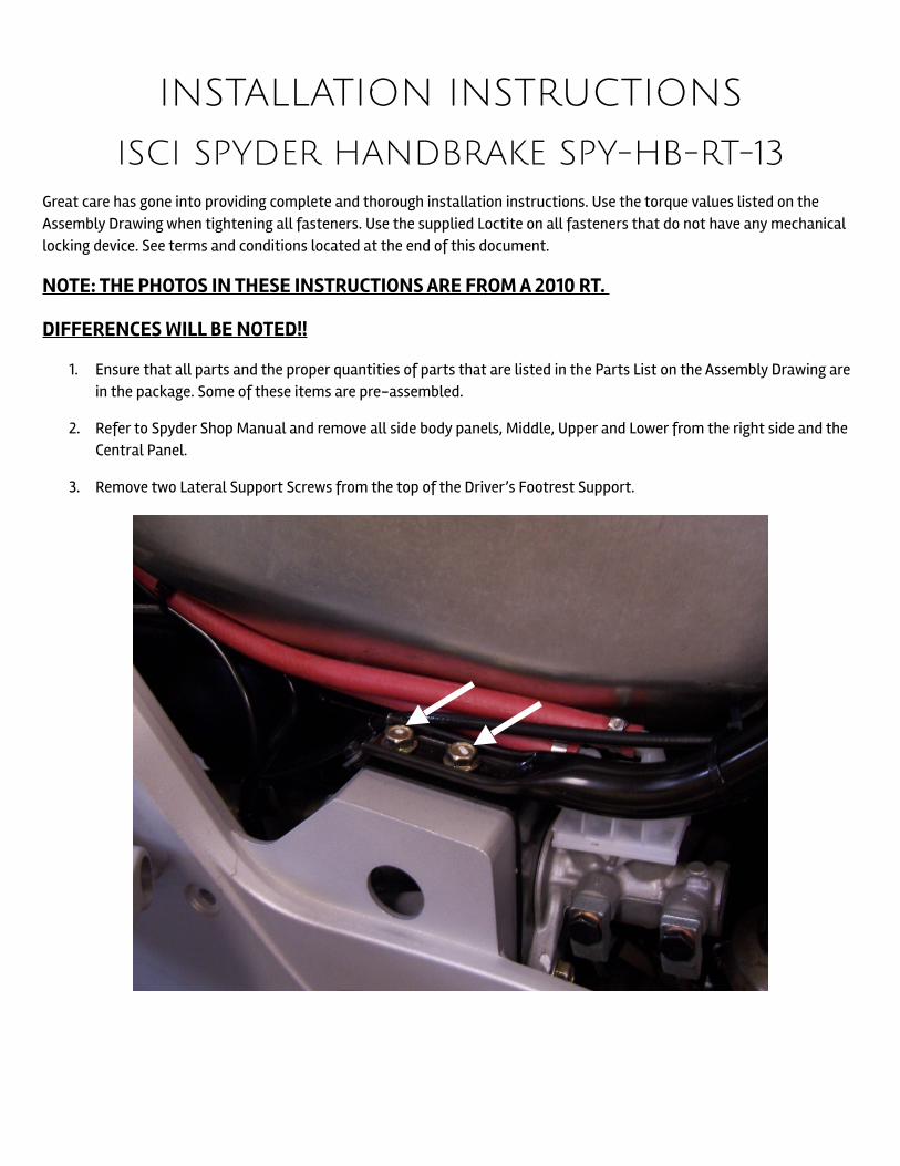
!4. Assemble Clevis Pin, 3/8” Spacer, and Washers and Spring as shown below.
!
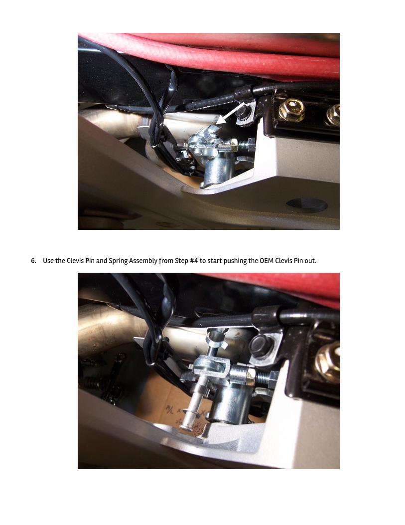
5. Unhook the Hook Lock from the Clevis on the Master Cylinder Rod. DO NOT REMOVE THE PIN FROM THE CLEVIS AT THIS TIME!!
!
!6. Use the Clevis Pin and Spring Assembly from Step #4 to start pushing the OEM Clevis Pin out.
!
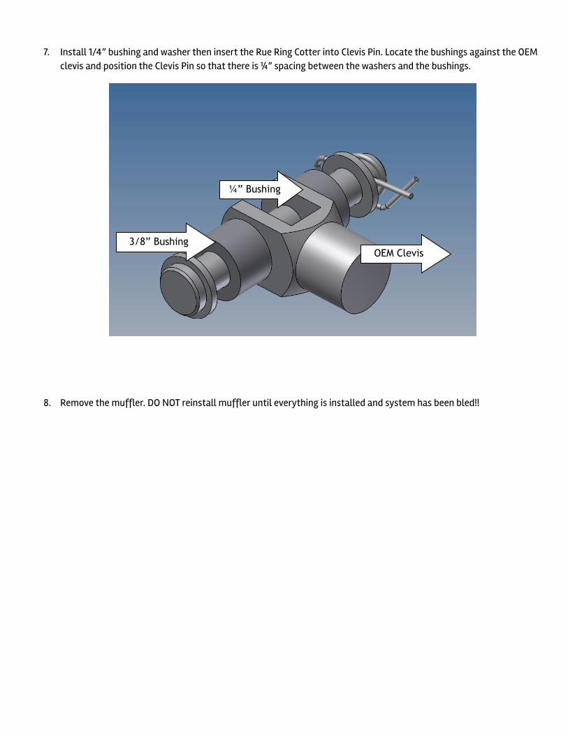
7. Install 1/4” bushing and washer then insert the Rue Ring Cotter into Clevis Pin. Locate the bushings against the OEM clevis and position the Clevis Pin so that there is ¼” spacing between the washers and the bushings.
!
!!
8. Remove the muffler. DO NOT reinstall muffler until everything is installed and system has been bled!!
¼” Bushing
3/8” Bushing OEM Clevis
!
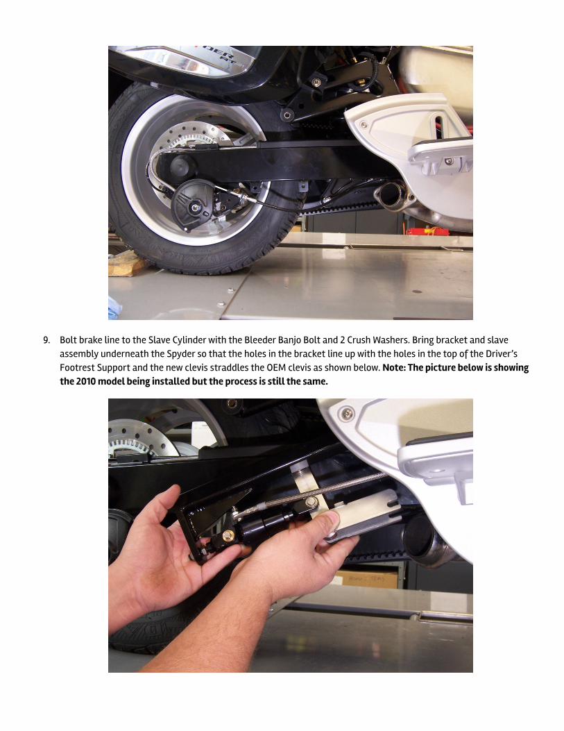
9. Bolt brake line to the Slave Cylinder with the Bleeder Banjo Bolt and 2 Crush Washers. Bring bracket and slave assembly underneath the Spyder so that the holes in the bracket line up with the holes in the top of the Driver’s Footrest Support and the new clevis straddles the OEM clevis as shown below. Note: The picture below is showing the 2010 model being installed but the process is still the same.
!
!
!
!
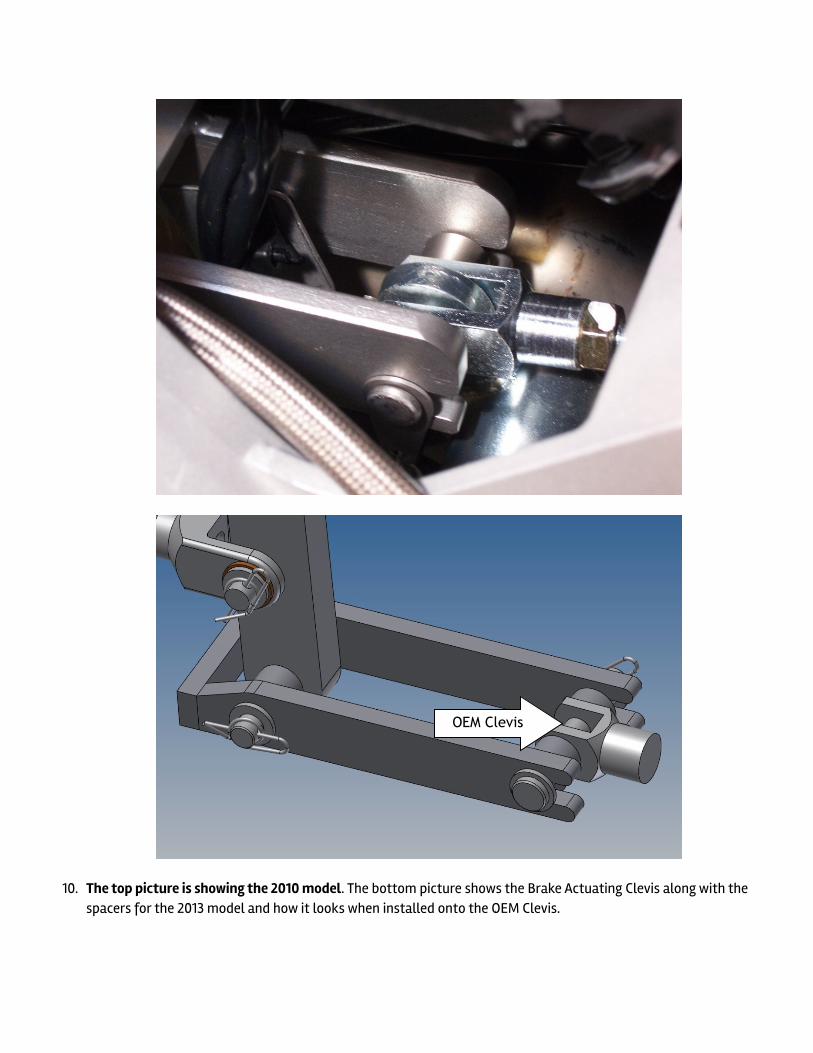
10. The top picture is showing the 2010 model. The bottom picture shows the Brake Actuating Clevis along with the spacers for the 2013 model and how it looks when installed onto the OEM Clevis.
!!
OEM Clevis
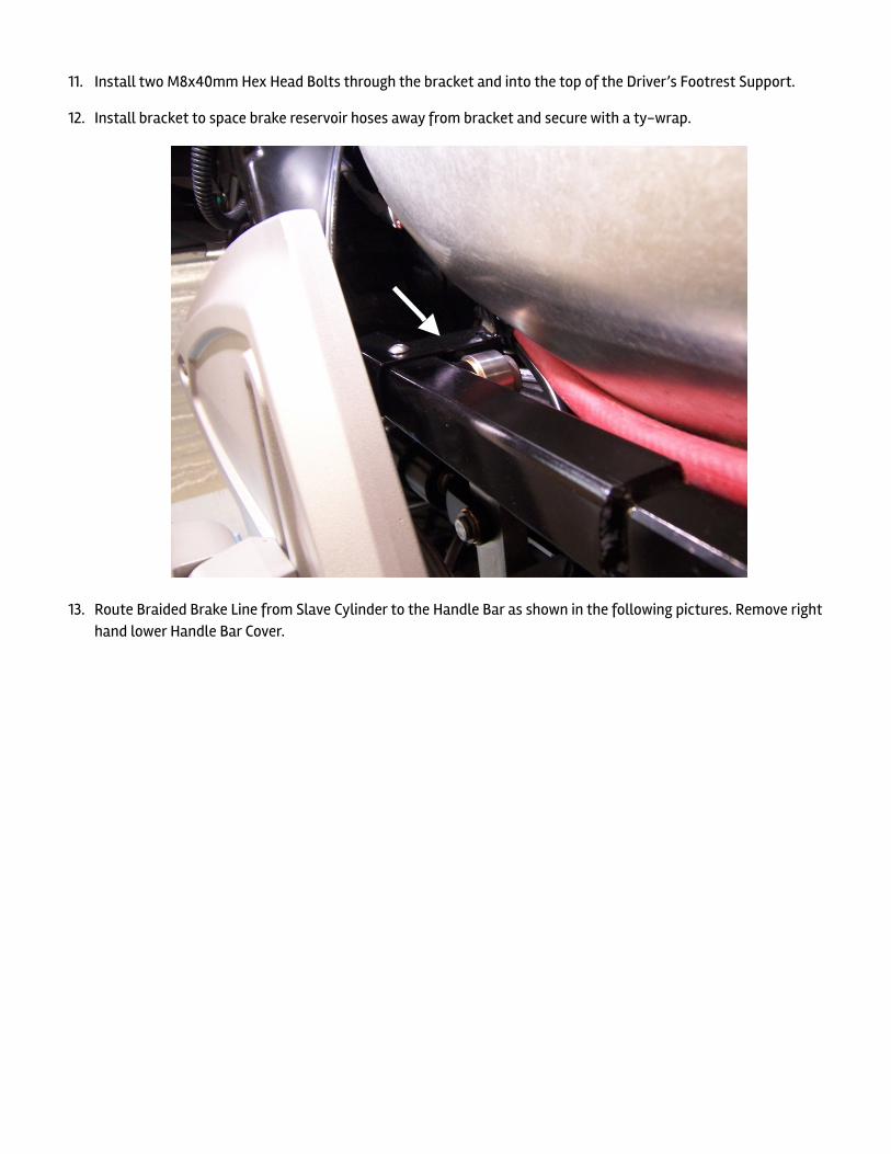
11. Install two M8x40mm Hex Head Bolts through the bracket and into the top of the Driver’s Footrest Support.
12. Install bracket to space brake reservoir hoses away from bracket and secure with a ty-wrap.
!
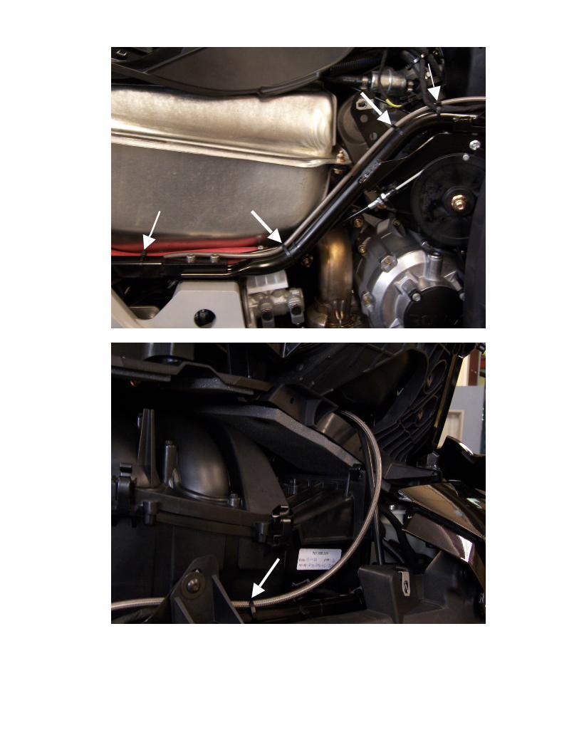
13. Route Braided Brake Line from Slave Cylinder to the Handle Bar as shown in the following pictures. Remove right hand lower Handle Bar Cover.
!
!
!
!!
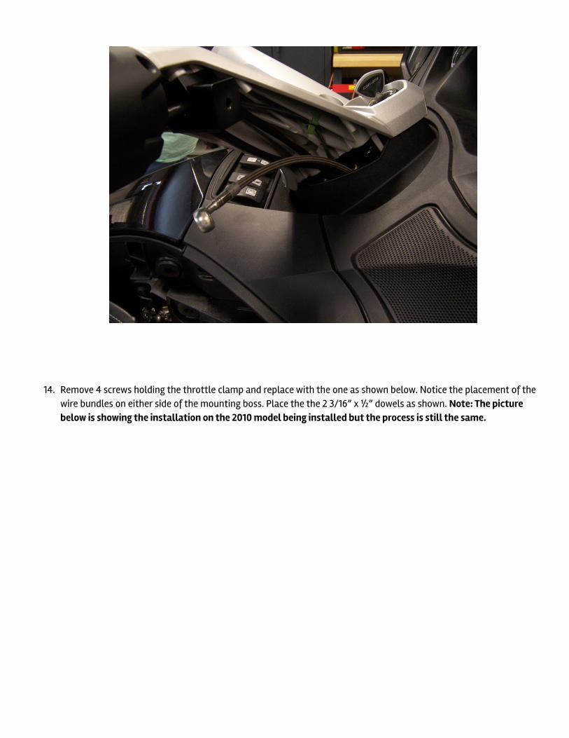
14. Remove 4 screws holding the throttle clamp and replace with the one as shown below. Notice the placement of the wire bundles on either side of the mounting boss. Place the the 2 3/16” x ½” dowels as shown. Note: The picture below is showing the installation on the 2010 model being installed but the process is still the same.
!
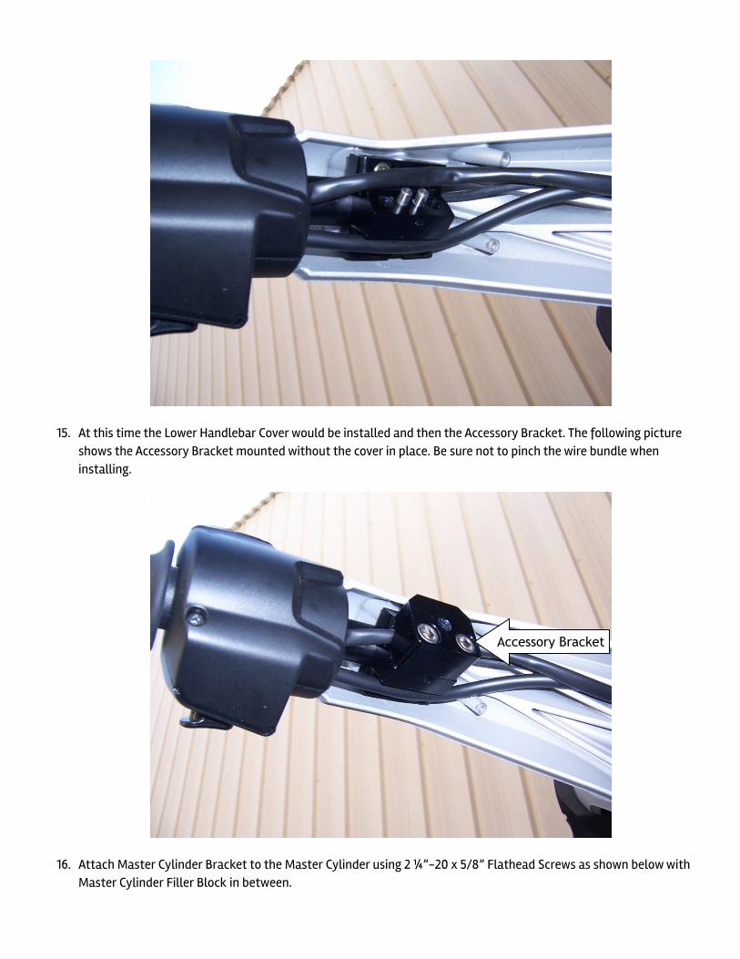
15. At this time the Lower Handlebar Cover would be installed and then the Accessory Bracket. The following picture shows the Accessory Bracket mounted without the cover in place. Be sure not to pinch the wire bundle when installing.
!
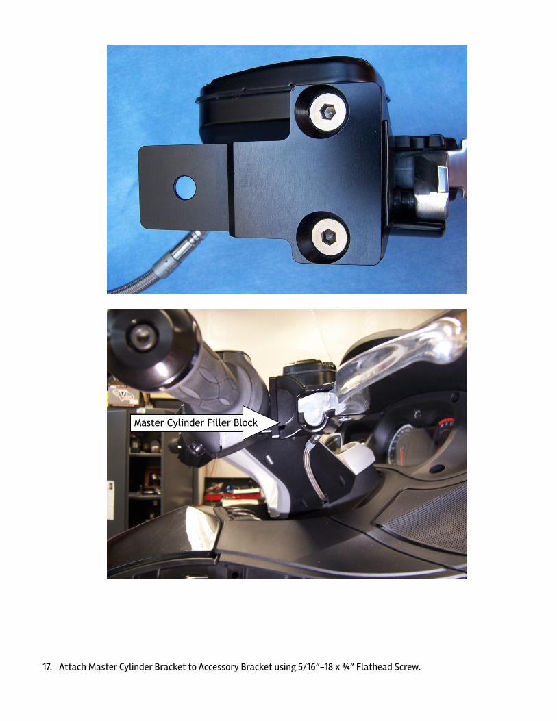
16. Attach Master Cylinder Bracket to the Master Cylinder using 2 ¼”-20 x 5/8” Flathead Screws as shown below with Master Cylinder Filler Block in between.
Accessory Bracket
!
!
!!
!17. Attach Master Cylinder Bracket to Accessory Bracket using 5/16”-18 x ¾” Flathead Screw.
Master Cylinder Filler Block
!
!
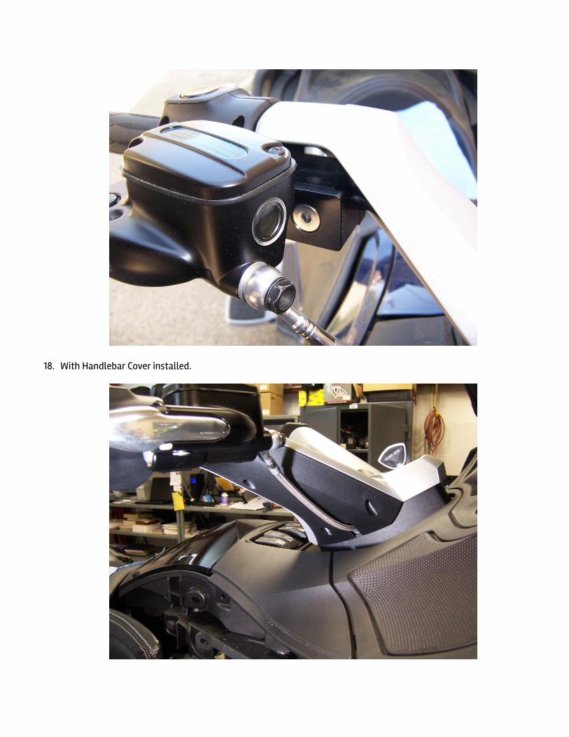
18. With Handlebar Cover installed.
!
19. Attach brake line to the master cylinder using the supplied black banjo bolt and two crush washers. Fill master cylinder with DOT 4 brake fluid and bleed till there is no air coming out of the bleeder valve. Connecting a clear tube to the bleeder will help from making a mess and you can easily see when there is no more air coming from the slave cylinder.
20. Use ty-wraps to secure brake line along the Lateral Support Tube and on the Slave Cylinder Mounting Bracket as shown on pages 6 and 7.
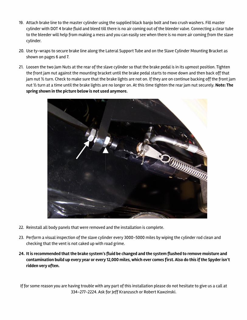
21. Loosen the two Jam Nuts at the rear of the slave cylinder so that the brake pedal is in its upmost position. Tighten the front jam nut against the mounting bracket until the brake pedal starts to move down and then back off that jam nut ½ turn. Check to make sure that the brake lights are not on. If they are on continue backing off the front jam nut ½ turn at a time until the brake lights are no longer on. At this time tighten the rear jam nut securely. Note: The spring shown in the picture below is not used anymore.
!
22. Reinstall all body panels that were removed and the installation is complete.
23. Perform a visual inspection of the slave cylinder every 3000-5000 miles by wiping the cylinder rod clean and checking that the vent is not caked up with road grime.
24. It is recommended that the brake system’s fluid be changed and the system flushed to remove moisture and contamination build up every year or every 12,000 miles, which ever comes first. Also do this if the Spyder isn’t ridden very often.
!If for some reason you are having trouble with any part of this installation please do not hesitate to give us a call at
334-277-2224. Ask for Jeff Kranzusch or Robert Kawzinski.

!