Embed Size (px)
Citation preview

KIT# 521440-1B06/03/14
KSR
O
A
D
M
A
S
T
E
R,
I
N
C.
ROADMASTER, Inc. 6110 NE 127th Ave. Vancouver, WA 98682 360-896-0407 fax 360-735-9300 www.roadmasterinc.com
BASEPLATE KIT INSTALLATION INSTRUCTIONS
Special tools needed:plastic pop rivet gun
fits Jeep Grand Cherokee and Dodge Durango
ITEM QTY NAME MATERIAL1...........4.......... 10mm x 1.5 x 90mm BOLT ............................................................................... 356115-002...........4.......... 10mm LOCK WASHER .................................................................................... 355715-003...........4.......... 3/8” FLAT WASHER ......................................................................................... 350304-004...........2.......... 1/2” x 3 1/2” BOLT ............................................................................................. 350103-005...........2.......... 1/2” x 2 1/4” BOLT ............................................................................................. 350098-006...........4.......... 1/2” LOCK WASHER ........................................................................................ 350309-007...........2.......... 1/2” HEX NUT ................................................................................................... 350258-008...........2.......... QUICK LINK ..................................................................................................... 200008-009...........2.......... 8” SAFETY CABLES ........................................................................................ 650648-0810.........2.......... 3/16” x 2” x 3” BACKING PLATE ...................................................................... A-00014711 .........2.......... 1 1/4” O.D. x 0.25 WALL x 1” PIPE SPACER ................................................... A-00094512.........1.......... DRIVER SIDE RECEIVER ............................................................................... C-00206213.........1.......... PASSENGER SIDE RECEIVER ....................................................................... C-00206314.........1.......... DRIVER SIDE ARM .......................................................................................... C-00206415.........1.......... PASSENGER SIDE ARM ................................................................................. C-00206516.........2.......... 3/16” x 1” x 2” THREADED BACKING PLATE W/ ROD ................................... C-00196417.........4.......... PLASTIC POP RIVET ....................................................................................... 350431-0018.........2.......... 1 1/4” O.D. x 0.25 WALL x 1” PIPE SPACER ................................................... A-00094519.........2.......... 3/16” x 1 1/2” x 3” BACKING PLATE ................................................................ A-00018520.........2.......... 1/2” HEX NUT ................................................................................................... 350258-0021.........2.......... 1/2” LOCK WASHER ........................................................................................ 350309-0022.........2.......... 1/2” x 2 1/4” BOLT ............................................................................................. 350098-0023.........2.......... 1/2” FLAT WASHER ......................................................................................... 350308-0024.........1.......... 1/2" SPLIT LOOM 4" ......................................................................................... 300089-0025.........2.......... ZIP TIES ........................................................................................................... 300140-10
1
2
3
45
6
7
8
910
11
12
13
14
15
1618
19
20
21
22
ITEMS 18,19,20,21,& 22 REQUIRED FOR VEHICLES WITHOUT TOW HOOKS

KIT# 521440-1B06/03/14
KS
Fig.A
Fig.B
This is one of our EZ series brackets, which allows the visible front portion of the bracket to be easily removed from the front of the
vehicle (Fig.A and Fig.B). The bracket consists of a main receiver brace, two removable front brac-es, and a hardware pack. The main receiver brace mounts to the frame rails and the bumper core. The removable front braces install in the main receiver brace. Before starting the installation, lay out the kit components in order, as they will be used. This will give you a visual idea of how the components work, and will also confirm that everything is pres-ent and accounted for.
IMPORTANT: All brackets must be assembled with all the bolts left loose for final adjustment and positioning (before tightening) unless otherwise instructed. All bolts must be torqued for proper strength. If more than one bolt is used per fastening point, the diagram may only show one.
• Use flat washers over all slotted holes • Use lock washers on all fasteners
• Installation of most mounting brackets requires moderate mechani-cal aptitude and skills. We strongly recommend professional installa-tion by an experienced installer.
• The installer must read the instructions and use all bolts and partssupplied. Failure to do so could result in loss of the towed vehicle.
• Use Loctite® Red on all bolts used for mounting this bracket.
• Every 3,000 miles, the owner must inspect the fasteners for propertorque, according to the bolt torque requirements chart on the last pageof these instructions. The owner must also inspect all mounts andbrackets for cracks or other signs of fatigue every 3,000 miles.Failure to do so could result in loss of the towed vehicle.
• The owner must check the vehicle manufacturer's instructions forthe proper procedure(s) to prepare the vehicle for towing. Somevehicles must be equipped with a transmission lube pump, an axle dis-connect, driveline disconnect or free-wheeling hubs before they can betowed. Failure to properly equip the vehicle will cause severe damageto the transmission.
• If running changes were made by the vehicle manufacturer after thisbracket was designed, some bolts or other fasteners in the hardwarepack may no longer be the correct size. It is the installer’s responsi-bility to verify that the bracket is securely fastened to the vehicle andfitted with the correct hardware to account for these changes. Failure tosecurely fasten the bracket could result in loss of the towed vehicle.
• If the towed vehicle has been in an accident, it must be properly re-paired before attaching the bracket. Do not install the bracket if anystructural frame damage is found. Failure to repair the damage couldresult in the loss of the towed vehicle.
ROADMASTER Limited Warranty, including One-Year Conditional Warranty Text and Product Registration Card, in Carton.
• Roadmaster manufactures many styles of brackets. If your brackethas removable arms, they must be removed before driving thevehicle, unless the arms can be pinned or padlocked in place.If not secured, the arms could vibrate out, resulting in non-warrantydamage or personal injury.
• Some motorhome chassis have such a tight turning radius that you candamage your motorhome, towed vehicle, tow bar or bracket while turningsharply. Before getting on the road, test your turning radius in anempty parking lot. Turning too sharply could result in non-warrantydamage to towing system, motorhome and/or towed vehicle.
• Do not back up with the towed vehicle attached or non-warrantydamage will occur to your towing system, motorhome and/or towedvehicle.
• The safety cables must connect the towing vehicle to the towedvehicle frame to frame, with the cables crossed, with enough slackfor sharp turns. Refer to the cable instructions for proper routing.Failure to leave enough slack in the safety cables, or failure to connectthe safety cables frame to frame, will result in the loss of the towedvehicle.
• This bracket is designed for use with ROADMASTER tow bars andROADMASTER adaptors only. Using this bracket with other brands,without an approved ROADMASTER adaptor, may result in non-warranty damage or injury.
• Do not use this document for custom fabrication, as it may not showall parts or structural components. Custom fabrication or an attempt tocopy this bracket design could result in loss of the towed vehicle.
• Upon final installation, the installer must inspect the bracket to en-sure adequate clearance, particularly around hoses, air conditionerlines, radiators, etc., or non-warranty damage to the towed vehiclewill result.
• This bracket is only warranteed for the original installation. Installinga used bracket on another vehicle is not recommended and will voidthe warranty.
Failure to follow these instructions can result in property damage, personal injury or even death.WARNINGWARNING
BASEPLATE KIT INSTALLATION INSTRUCTIONS
ROADMASTER, Inc. 6110 NE 127th Ave. Vancouver, WA 98682 360-896-0407 fax 360-735-9300 www.roadmasterinc.com

KIT# 521440-1B06/03/14
KS
1. Important: please use all supplied bolts and parts and read all instructions carefully before beginning thisinstallation. The majority of questions you may have can be answered within the text, and proper installation will ensure safe and secure travel. Now, begin the installation. For '14 and later models only: remove two plastic fasteners attaching the upper fascia to the core support (Fig.C).
2. Remove two 13mm (head) bolts, five 10mm (head) bolts and one plastic fastener attaching the lower splash shield tothe subframe and core support (Fig.D).
3. On each side, remove one 10mm screw and use apair of side cutters to remove two plastic pop rivets attach-ing the fender liner to the fascia (Fig.E — passenger side). Note: due to manufacturing variances, some vehicles may have plastic fasteners instead.
4. On each side, pull out on the lower edge of the fenderflair to detach it from the fascia (Fig.F). Note: due to manu-facturing variances, fender flair may not be present.
5. Twist counterclockwise to remove the five plastic fas-teners attaching the lower fascia to the core support and splash shield (Fig.G — driver's side).
Fig.D
Fig.E Fig.F
Fig.G
BASEPLATE KIT INSTALLATION INSTRUCTIONS
ROADMASTER, Inc. 6110 NE 127th Ave. Vancouver, WA 98682 360-896-0407 fax 360-735-9300 www.roadmasterinc.com
All illustrations and specifications contained herein are based on the latest information available at the time of publication approval. ROADMASTER, INC. reserves the right to make changes at any time without notice in material, specification and models or to discontinue models.
Fig.C

KIT# 521440-1B06/03/14
KS
6. For '14 and later Summit models only: carefully push in on the corner of the fascia to release the locking pin. Then,pull down and forward on the bottom of the fascia to release it at the spot indicated by the yellow arrow in Figure H. Now, pull out and forward on the corners of the fascia to remove it.
For all other models: pull out and forward on the corners of the fascia to remove it (Fig.I).
7. Support the subframe with a jack stand.
Fig.J
BASEPLATE KIT INSTALLATION INSTRUCTIONS
ROADMASTER, Inc. 6110 NE 127th Ave. Vancouver, WA 98682 360-896-0407 fax 360-735-9300 www.roadmasterinc.com
All illustrations and specifications contained herein are based on the latest information available at the time of publication approval. ROADMASTER, INC. reserves the right to make changes at any time without notice in material, specification and models or to discontinue models.
Fig.K
8. Trim the passenger side air deflector using the yellowlines in Figure J as a guide for trimming.
9. On each side, remove three 10mm (head) bolts at-taching the air deflector to the bumper core and radiator support (Fig.K). Note: some models may not have this air deflector. If that is the case, proceed to the next step.
Caution! Under no circumstances should you attempt to move, adjust or disconnect the ACC unit, if the vehicle is so equipped. Doing so may cause cruise control malfunction and/or computer error codes that may require the dealership to repair or reset.
10. For models without tow hooks: skip to step 13.
For models with tow hooks: complete steps 10through 12. Remove the 30mm nut attaching the tow hook to the rear of the tow hook bracket (Fig.L).
Fig.L
Fig.H Fig.I
KIT# 521440-1B06/03/14
KS
BASEPLATE KIT INSTALLATION INSTRUCTIONS
ROADMASTER, Inc. 6110 NE 127th Ave. Vancouver, WA 98682 360-896-0407 fax 360-735-9300 www.roadmasterinc.com
All illustrations and specifications contained herein are based on the latest information available at the time of publication approval. ROADMASTER, INC. reserves the right to make changes at any time without notice in material, specification and models or to discontinue models.
Fig.O Fig.P
Fig.Q
11. Working on the driver's side only, remove the two front 16mm (head) bolts attaching the front of the tow hook to thebumper core (Fig.M).
12. Remove two 16mm (head) bolts attaching the tow hook mount to the bottom of the frame rail (Fig.N). The tow hookmount and bracket will not be replaced. Note: retain the tow hook mount and bracket so they can be replaced if the brack-et is ever removed. Now, place the supplied 4" split loom over the metal cooling line and secure the ends in place with zipties in the spots indicated by yellow arrows in Figure N.
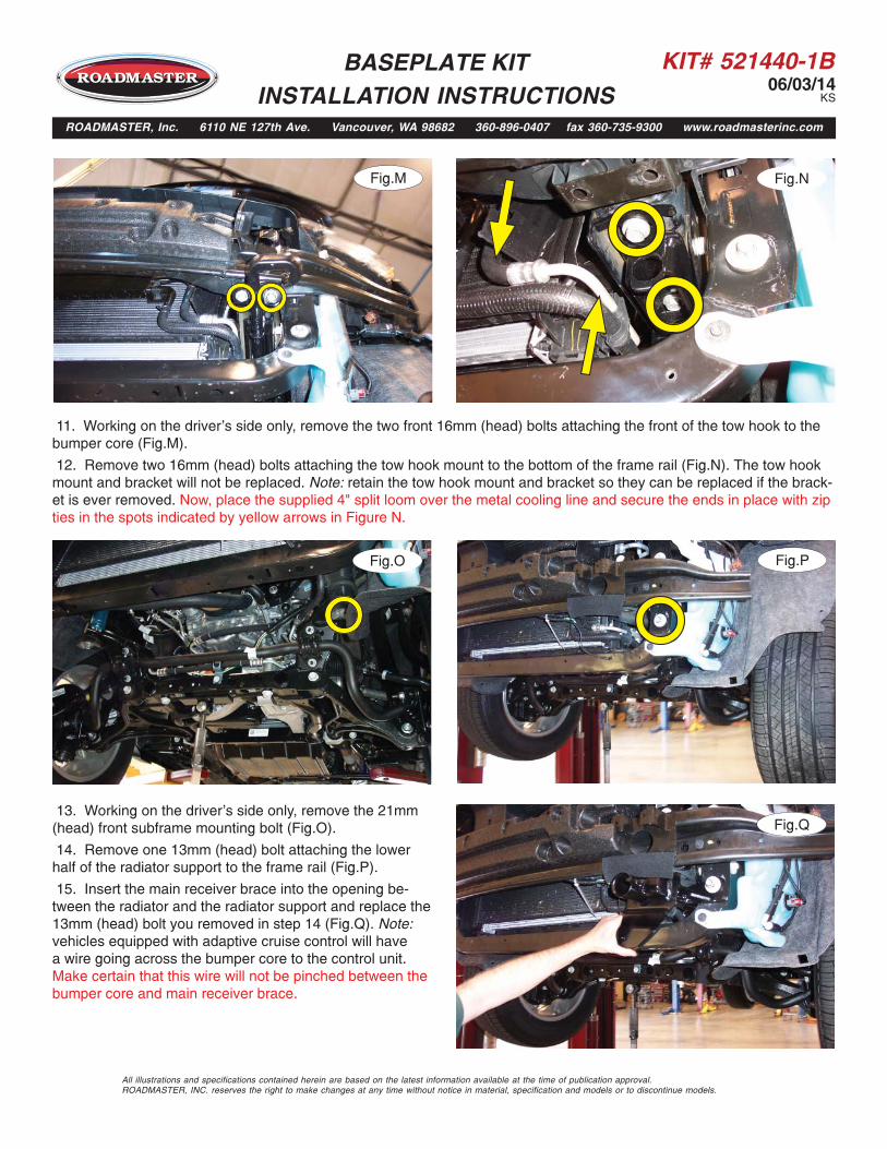
13. Working on the driver's side only, remove the 21mm(head) front subframe mounting bolt (Fig.O).
14. Remove one 13mm (head) bolt attaching the lowerhalf of the radiator support to the frame rail (Fig.P).
15. Insert the main receiver brace into the opening be-tween the radiator and the radiator support and replace the13mm (head) bolt you removed in step 14 (Fig.Q). Note:vehicles equipped with adaptive cruise control will havea wire going across the bumper core to the control unit.Make certain that this wire will not be pinched between thebumper core and main receiver brace.
Fig.NFig.M

KIT# 521440-1B06/03/14
KS
BASEPLATE KIT INSTALLATION INSTRUCTIONS
ROADMASTER, Inc. 6110 NE 127th Ave. Vancouver, WA 98682 360-896-0407 fax 360-735-9300 www.roadmasterinc.com
Fig.T
Fig.V18. Repeat steps 13 through 17 for the passenger side.
19. For models with tow hooks: using the 16mm (head)bolts you removed in step 11, bolt through the outside up-per mounting point of the main receiver brace and into thetow hook mount (Fig.T).
For models without tow hooks: on each side, place one of the 1¼" x 1" pipe spacers between the outside mounting point on the main receiver brace and the bumper core. Place one of the supplied ½" flat washers over a ½" x 2¼" bolt and bolt up through the main receiver brace, pipe spacer and into one of the supplied 3/16" x 1½" x 3" back-ing plates. Finish with a ½" lock washer and nut (Fig.U).
20. Working on the driver's side only, and using the insideupper mounting point of the main receiver brace as a tem-plate, drill a ½" hole through the bottom of the bumper core(Fig.V).
16. Place one 3/8" flat washer and one 10mm lock washer over two of the supplied 10mm x 1.5 x 90mm bolts, and onboth sides of the radiator support, bolt through the main receiver brace and into the two weld nuts located in the bottomthe frame rail (Fig.R).
17. Place thread lock on the 21mm (head) subframe bolt that you removed in step 13 and bolt through the lower mount-ing point of the main receiver brace (Fig.S).
Fig.U
Fig.SFig.R
All illustrations and specifications contained herein are based on the latest information available at the time of publication approval. ROADMASTER, INC. reserves the right to make changes at any time without notice in material, specification and models or to discontinue models.

KIT# 521440-1B06/03/14
KS
BASEPLATE KIT INSTALLATION INSTRUCTIONS
ROADMASTER, Inc. 6110 NE 127th Ave. Vancouver, WA 98682 360-896-0407 fax 360-735-9300 www.roadmasterinc.com
Fig.AA
Fig.Z
21. Place one of the supplied 3/16" x 1" x 2" threaded backing plate with wire into the opening in the end of the bumpercore and over the inside upper mounting point of the main receiver brace (Fig.W).
22. Place a 1¼" x 1" pipe spacer between the upper inside mounting point and the bumper core (Fig.X). Place a ½" lockwasher over a ½" x 2¼" bolt and bolt through the inside upper mounting point of the main receiver brace, bumper coreand into the threaded backing plate (Fig.Y).
23. Repeat steps 20 through 22 for the passenger side.
24. Torque all bolts to the bolt torque requirements foundat the end of this document, starting with the bumper coremounting points. Using a pair of pliers, snap the wires offthe backing plates.
25. On each side, using a ½" drill bit, and the lowermounting point of the main receiver brace as a template,drill through the front and back of the radiator support(Fig.Z). Note: use caution and a metal plate to avoid drillinginto engine components.
26. On each side, place one of the supplied ½" x 3½"bolts through the main receiver brace and core support.Finish with one of the supplied 3/16" x 2" x 3" backingplates, ½" lock washer and ½" nut (Fig.AA — driver's side).
Fig.Y
Fig.XFig.W
All illustrations and specifications contained herein are based on the latest information available at the time of publication approval. ROADMASTER, INC. reserves the right to make changes at any time without notice in material, specification and models or to discontinue models.

KIT# 521440-1B06/03/14
KS
BASEPLATE KIT INSTALLATION INSTRUCTIONS
ROADMASTER, Inc. 6110 NE 127th Ave. Vancouver, WA 98682 360-896-0407 fax 360-735-9300 www.roadmasterinc.com
27. On each side, if the vehicle is so equipped, hold the side air deflector in place over the main receiver brace and trimusing the yellow lines in Figure BB as a guide for trimming.
28. Trim the lower air deflector (Fig.CC) on both sides, using the yellow lines as a reference for trimming. Note: makecertain that you do not cut off any of the mounting tabs on the air deflector. Figure DD Shows the completed trimming onone side.
29. For '14 and later Summit models only: skip tothe supplement found at the end of these instructions forfascia trimming and replacement. For all other models:proceed to the next step.
30. Reinstall the fascia by reversing steps 1 through 6.Note: for some models, you will need a pop rivet gun andthe supplied pop rivets to reattach the fender liners. FigureEE shows the completed installation on a 2014 JeepGrand Cherokee Overland.
31. Insert the removable front bracket arms into the frontreceiver braces, and twist each one 90 degrees to lock.
32. Attach the 8" safety cables with the cable connectors(Q-Links) to the front of the receiver braces (Fig.FF).
Fig.BB Fig.CC
Fig.DD Fig.EE
Fig.FF
All illustrations and specifications contained herein are based on the latest information available at the time of publication approval. ROADMASTER, INC. reserves the right to make changes at any time without notice in material, specification and models or to discontinue models.

KIT# 521440-1B06/03/14
KS
BASEPLATE KIT INSTALLATION INSTRUCTIONS
ROADMASTER, Inc. 6110 NE 127th Ave. Vancouver, WA 98682 360-896-0407 fax 360-735-9300 www.roadmasterinc.com
BOLT TORQUE REQUIREMENTS
METRIC BOLTSThread Size Grade Plated / Unplated12mm-1.25 ........8.8 ............70 ft./lb. 65 ft./lb. 12mm-1.5 ..........8.8 ............66 ft./lb. 61 ft./lb.12mm-1.75 ........8.8 ...........65 ft./lb. 60 ft./lb.14mm-2.0 ..........8.8 .........104 ft./lb. 97 ft./lb.
METRIC BOLTSThread Size Grade Plated / Unplated 8mm-1.0 ............8.8 ............20 ft./lb. 18 ft./lb. 8mm-1.25 .........8.8 ............19 ft./lb. 18 ft./lb.10mm-1.25 ........8.8 ...........38 ft./lb. 36 ft./lb.10mm-1.5 ..........8.8 ...........37 ft./lb. 35 ft./lb.
STANDARD BOLTSThread Size Grade Torque5/16..................... 5 ........................... 13 ft./lb. 3/8....................... 5 ........................... 23 ft./lb.7/16..................... 5 ........................... 37 ft./lb.1/2....................... 5 ........................... 56 ft./lb.5/8....................... 5 ......................... 150 ft./lb.
Note: The torque values represented below are intended as general guidelines. Torque requirements for specific applications may vary. Roadmaster does not warrant this information to be accurate for all applications and disclaims all liability for any claims or damages which may result from its use.
All illustrations and specifications contained herein are based on the latest information available at the time of publication approval. ROADMASTER, INC. reserves the right to make changes at any time without notice in material, specification and models or to discontinue models.
33. Attach the ends of the safety cables to the tow vehicle's safety cables.
34. Install the tow bar to the mounting bracket according to the manufacturer's instructions.
Note: if the bracket is so equipped, the holes in the alignment tabs which are welded to the arms and main receiver braces are for padlocks only. Under no circumstances should you bolt the alignment tabs together. Bolting the alignment tabs together may result in non-warranty damage to the bracket.

KIT# 521440-1B06/03/14
KS
All illustrations and specifications contained herein are based on the latest information available at the time of publication approval. ROADMASTER, INC. reserves the right to make changes at any time without notice in material, specification and models or to discontinue models.
BASEPLATE KIT INSTALLATION INSTRUCTIONS
ROADMASTER, Inc. 6110 NE 127th Ave. Vancouver, WA 98682 360-896-0407 fax 360-735-9300 www.roadmasterinc.com
Fig.B
Fig.C
1. Trim the fascia as shown in Figure A. Use the yellow lines as a reference for trimming. Then, proceed to the stepsbelow.
2. On each side, remove a metal clip attaching the fender liner mounting strip to the fascia (Fig.B) and pull the strip offthe tab and let it hang for now.
Fig.A
Trimming and Fascia Replacement SupplementThis section pertains to '14 and later Summit models only.
For all other models, see the instructions on the previous page.
3. Reinstall the fascia but leave the corners unattached for now. Push in on the fascia so the locking pin moves from theoutside of the fender (Fig.C) to the inside of the fender (Fig.D).
Fig.D
locking pinlocking pin
locking pinlocking pin

KIT# 521440-1B06/03/14
KS
BASEPLATE KIT INSTALLATION INSTRUCTIONS
ROADMASTER, Inc. 6110 NE 127th Ave. Vancouver, WA 98682 360-896-0407 fax 360-735-9300 www.roadmasterinc.com
All illustrations and specifications contained herein are based on the latest information available at the time of publication approval. ROADMASTER, INC. reserves the right to make changes at any time without notice in material, specification and models or to discontinue models.
4. Lift up on the fender liner mounting strip to raise thelocking pin, and push it into its locking position. Reattach the mounting clip, reversing step 2 in this supplement. Figure E shows how the completed installation should look once the locking pin is seated.
5. Finish reinstalling the fascia, reversing steps 1 through5 found at the beginning of these instructions.
6. Insert the removable front bracket arms into the frontreceiver braces, and twist each one 90 degrees to lock.
7. Attach the 8" safety cables with the cable connectors(Q-Links) to the front of the receiver braces.
8. Attach the ends of the safety cables to the tow ve-hicle's safety cables.
9. Install the tow bar to the mounting bracket according to
Fig.E
fastener properly fastener properly seated in U-shaped seated in U-shaped
mountmount
the manufacturer's instructions.
Note: if the bracket is so equipped, the holes in the alignment tabs which are welded to the arms and main receiver braces are for padlocks only. Under no circumstances should you bolt the alignment tabs together. Bolting the alignment tabs together may result in non-warranty damage to the bracket.