Embed Size (px)
Citation preview

1
Installation instructions
IBC AeroFix
Version 17.01 Date: 27-Jun-2017

2
Version 17.01, 27-Jun-2017
Contents
0. Introduction .........................................................................................................................................3
01. Tool list .............................................................................................................................................4
02. General information, standards and regulations ..................................................................................4
03. System variants ................................................................................................................................8
04. Technical data...................................................................................................................................9
05. System planning ............................................................................................................................. 10
06. System design/dimensioning ........................................................................................................... 13
07. System installation .......................................................................................................................... 14
08. System security device .................................................................................................................... 42
09. Final inspection ............................................................................................................................... 44
10. Parts list .......................................................................................................................................... 45
11. Appendix ........................................................................................................................................ 51
12. Notes .............................................................................................................................................. 56

3
Version 17.01, 27-Jun-2017
0. Introduction
Dear customer,
Congratulations, you have chosen an IBC product! Now you can enjoy the quality and reliability of the IBC
AeroFix flat roof system.
To ensure that you can install and start up your IBC AeroFix flat roof system quickly and simply we have
enclosed detailed assembly instructions. They should help you to quickly become familiar with the
assembly of the bracket and the modules.
Please read these instructions carefully before installation. If you still have questions after reading them,
please contact your IBC partner, who will be happy to assist you.
We wish you a sunny day!
Your team
IBC SOLAR AG

4
Version 17.01, 27-Jun-2017
01. Tool list
Cordless screwdriver with various bits (Torx 40, SW8 socket, ...)
Bit holder 300 mm
Pencil
Tape measure
Folding rule
Plumb line
Angle grinder with diamond grinding wheel
Torx screwdriver with T-handle, size TX40
Torque wrench
Assembly gloves
Assembling jig
Static friction measureing device (in the planning phase)
02. General information, standards and regulations
The IBC AeroFix flat roof system is for mounting solar modules onto flat roofs.
The modules are attached on supports using clamps.
The number of parts varies depending on installation size..
Important information:
Your IBC AeroFix flat roof system will be delivered complete with all accessories!
Before you begin, please check that all parts are included by using the attached packing list and
parts list.
Electrical work must be carried out by a qualified electrician!
The processing guidelines and in individual cases specific guidelines from the relevant
manufacturer for the roofing and modules must be adhered to!

5
Version 17.01, 27-Jun-2017
Condition for the 10-year guarantee to be granted: this only applies with the use of IBC
components. The guarantee is not valid for components from other suppliers. Complete
guarantee conditions are stated in the guarantee document.
We advise the use of gloves to avoid injuries
Other important information and dimensioning standards
The entire PV system must be mounted according to the generally recognised technical regulations.
Please ensure that you observe the accident prevention regulations of the German employer‘s liability
insurance associations (Berufsgenossenschaften), in particular:
BGV A1 General instructions
BGV A3 Electrical systems and equipment
BGV C22 Construction work
BGV D36 Ladders and steps
Please ensure that installation is adapted to on-site conditions and corresponds to the respective generally
recognised technical regulations. Local regulations must be observed.
Please observe all regulations and guidelines under public law during planning, erection, operation and
maintenance of grid-connected PV plants including the following: EN standards, DIN standards, TAB,
accident prevention regulations, the guidelines from the association of property insurers (VDS – fire
protection guidelines), the professional guidelines of the roofing association and general guidelines (e.g.
timber structures, roofing and roof-sealing works).
Please note in particular (this is not an exhaustive list):
DIN / VDE 0100, particularly part 712 (erection of power installations with nominal voltage up to
1000 V)
DIN / VDE 0298 (electric cables)
VDI 6012 (local energy systems in buildings – photovoltaic)
DIN / VDE 0126 (solar energy systems for domestic use)
DIN / VDE 0185 part 1 to 4 (lightning protection)
DIN 18338 Roof covering and roof sealing works
DIN 18451 Scaffolding work
DIN 18015 Planning and erection of electrical installations in residential buildings

6
Version 17.01, 27-Jun-2017
TAB (technical closing conditions for connecting to the low-voltage grid of power supply
companies)
VDEW guidelines (guidelines for connection and parallel operation of decentralised power
generation in the low-voltage grid)
Notes on solar from the German Institute of Civil Engineering (DIBt), in the current edition
DIBt building regulation list, in the current edition
DIN 4102-1:1998 Fire behaviour of building materials and elements – part 1: Building materials;
classification, requirements and tests
DIN EN 13501-1:2010-01 Fire classification of construction products and building elements – part
1: Classification using the results from fire behaviour tests on construction products
EN 1991-1-3 (General actions – snow loads)
EN 1991-1-4 (General actions – wind loads)
EN 1993-1-1 Design of steel structures: General rules and rules for buildings
EN 1995-1-1 Design of timber structures
EN 1999-1-1 Design of aluminium structures
General certificate of building approval Z-30.3-6: Products, connecting devices and structural
components made from stainless steel
Solar modules
Framed solar modules may only be used if they fulfill the following criteria:
Module width: 950 – 1000 mm
Module length: 1630 – 1700 mm
Module manufacturers approval regarding module clamping
Hold valid IEC 61215 / IEC 61646 and protection class II / IEC 61730
Framed solar modules
Please note that the guarantee for the solar modules will expire if modifications are made to the module
frames (e.g. by drilling additional holes). For warranty reasons, the assembly instructions from the
respective solar module manufacturer must be strictly adhered to.

7
Version 17.01, 27-Jun-2017
Lightning and surge protection
Please note that the lightning and surge protection of the PV system is to meet the current requirements
for
DIN / VDE 0185 part 1 to 4,
DIN / VDE 0100 part 712 and
VdS 2010
For more detailed information please refer to the local regulations and the aforementioned standards and
guidelines.
In general we recommend that you integrate the assembly system and the module frames into the local
potential equalisation and use surge protection devices.
Potential equalisation is always necessary if the solar modules used do not meet requirements for
protection class II and/or transformerless inverters are used.
The cross-section of the potential equalisation conductor must correspond to the main DC cables but must
be at least 6 mm² (copper).
If the building has a lightning protection system and the PV generator is not in the protection area of the
arresting device, then the module frame and assembly system must be integrated into the external
lightning protection and surge protection devices must also be installed.
The electroconductive connection must be implemented with at least 16 mm² (copper).
Cable routing
Even when you are installing the frame, certain points regarding cable routing and wiring should be kept in
mind.
To avoid surge voltage couplings from lightning strikes, the resulting conductor loop must be kept
as small as possible.
The cable routing must allow for any future slipping caused by snow and ice.
Water must not be allowed to collect around the wiring, continuous water drainage must be
provided.
The wires must be installed with maximum possible UV and weather protection.

8
Version 17.01, 27-Jun-2017
03. System variants
Southern orientation
East-west orientation
Fig. 1: AeroFix 15-S / AeroFix 15-S Kits
Fig. 2: AeroFix 10-S
Fig. 3: AeroFix 10-EW beginning / ending with wind plates
Fig. 4 AeroFix 10-EW beginning / ending with modules

9
Version 17.01, 27-Jun-2017
04. Technical data
IBC AeroFix 15-S 10-S 10-EW
Application purpose Flat roof Flat roof Flat roof
Inclination (*) 15 10 10
Module orientation South South East-west
Max. permissible roof pitch (*) 10 10 10
Module width (mm) *A 950-1000 950-1000 950-1000
Module length (mm) *B 1630-1700 1630-1700 1630-1700
Weight (kg/m²) *C 7 8 11
Linear load (kg/m) *D 13 14 18
Center-to-center distance (m) 1.8 1.6 2.3
Minimum module field size zone H zone F and G
none 2x3 or 3x2
none 2x3 or 3x2
none 2x3 or 3x2
Maximum layout (thermal separation) 15 x 15 15 x 15 14 x 15
Minimum distance to roof edge (m) no no no
Material Aluminium stainless steel
Aluminium stainless steel
Aluminium stainless steel
Max. building height (m) *E 25 25 25
Approx. space reqirement m²/kWp (1,65 x 0,99 module)
10 10
Tab. 1: Technical data
Product guarantee in accordance with complete guarantee conditions in the version valid at the time of
assembly that you received from your IBC SOLAR trade partner. Guarantee assumes assembly is in
accordance with applicable assembly instructions. We reserve the right to make modifications which will
improve our product.
*A Approval required from module manufacturer
*B Other lengths on request
*C regular weight including mountings systems, roof protection matt and module (20 kg)
*D Depending on rail distance
*E Building heights >25 m are possible after isolated case check.

10
Version 17.01, 27-Jun-2017
05. System planning
The planning and static calculations of AeroFix flat roof systems is carried out using IBC PV Manager
software or based on the checklist to be submitted with the associated module layout plan, which can be
used to assess the degree of utilisation and the suitability of the assembly components for your roof.
The proof of the plant safety and the static load capacity of the system components have to be
calculated for every single project!
Before initiating the planning phase, there must be an extensive check of the existing building and
technical documentation must be completed. In particular, the constructor should be informed of any
damage to the roof cladding. The functionality of existing roof waterproofing should be provided for the
operating period of the new PV system to be installed.
Drainage
The customer must check that the structural condition is consistent with the design (building size, roof
pitch, roof cladding, obstacles etc.).
It must be ensured at all times that rain water is discharged to drainage collection points and this should be
incorporated into the planning of the PV system.
Pitched roofs
For roof pitches >3° is required securing the module fields in the direction of the roof pitch. This can be
done for example with east-west orientated roofs using a ground rail coupling to be taken across the roof
ridge.
Restriction of module field sizes
Due to different linear expansion coefficients for the structural profiles compared to those for the roof
cladding, there may be thermal constraints on the roof waterproofing. This is excluded by restricting the
module field sizes (splitting individual module fields).
AeroFix 15-S and AeroFix 10-S must be separated at the latest after 15 rows and after 15 modules in the
row.
AeroFix 10-EW must be separated at the latest after 14 rows (7-V rows) and after 15 modules in the row.
The field beginning and ending with modules is not counted as a row.

11
Version 17.01, 27-Jun-2017
Load-bearing reserve
In order to apply the additional loads from the PV system onto the roof, the load-bearing capacity of the
roof and the insolation must be assured by a static expert before planning the installation of the
photovoltaic system.
Important information:
The assembly system including the modules will load 7 kg/m² (11 kg/m²) to the surface of the roof.
Any additional ballast required to secure the system must also be taken into consideration in accordance
with static calculations. On average, loadings of approx. 5-10 kg/m² are to be expected.
Fig. 7 thermal separation within the module row
Fig. 6 AeroFix South separation between rows
Fig. 5 AeroFix EW separation between rows
12
Version 17.01, 27-Jun-2017
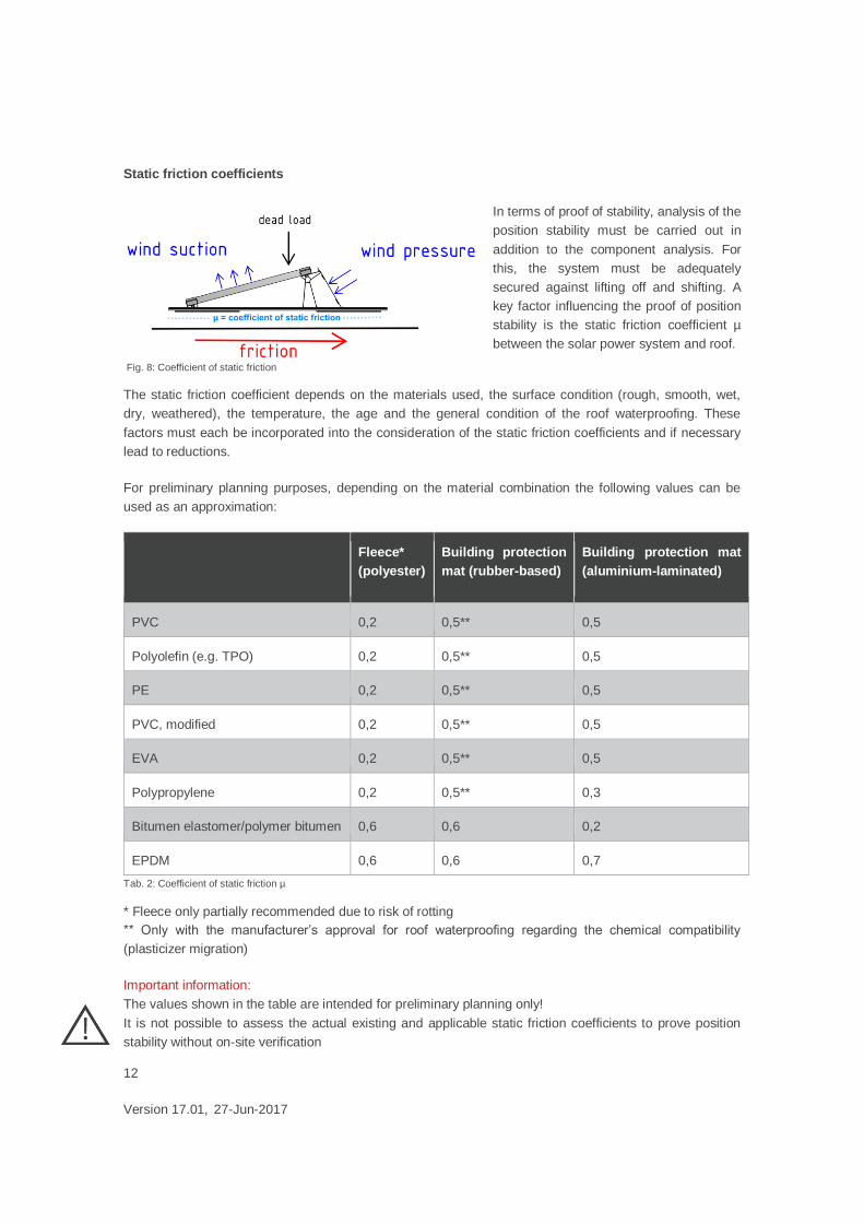
Static friction coefficients
In terms of proof of stability, analysis of the
position stability must be carried out in
addition to the component analysis. For
this, the system must be adequately
secured against lifting off and shifting. A
key factor influencing the proof of position
stability is the static friction coefficient µ
between the solar power system and roof.
The static friction coefficient depends on the materials used, the surface condition (rough, smooth, wet,
dry, weathered), the temperature, the age and the general condition of the roof waterproofing. These
factors must each be incorporated into the consideration of the static friction coefficients and if necessary
lead to reductions.
For preliminary planning purposes, depending on the material combination the following values can be
used as an approximation:
Fleece*
(polyester)
Building protection
mat (rubber-based)
Building protection mat
(aluminium-laminated)
PVC 0,2 0,5** 0,5
Polyolefin (e.g. TPO) 0,2 0,5** 0,5
PE 0,2 0,5** 0,5
PVC, modified 0,2 0,5** 0,5
EVA 0,2 0,5** 0,5
Polypropylene 0,2 0,5** 0,3
Bitumen elastomer/polymer bitumen 0,6 0,6 0,2
EPDM 0,6 0,6 0,7
Tab. 2: Coefficient of static friction µ
* Fleece only partially recommended due to risk of rotting
** Only with the manufacturer’s approval for roof waterproofing regarding the chemical compatibility
(plasticizer migration)
Important information:
The values shown in the table are intended for preliminary planning only!
It is not possible to assess the actual existing and applicable static friction coefficients to prove position
stability without on-site verification
Fig. 8: Coefficient of static friction
13
Version 17.01, 27-Jun-2017
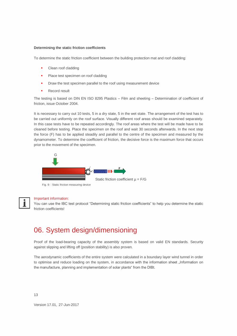
Determining the static friction coefficients
To determine the static friction coefficient between the building protection mat and roof cladding:
Clean roof cladding
Place test specimen on roof cladding
Draw the test specimen parallel to the roof using measurement device
Record result
The testing is based on DIN EN ISO 8295 Plastics – Film and sheeting – Determination of coefficient of
friction, issue October 2004.
It is necessary to carry out 10 tests, 5 in a dry state, 5 in the wet state. The arrangement of the test has to
be carried out uniformly on the roof surface. Visually different roof areas should be examined separately.
In this case tests have to be repeated accordingly. The roof areas where the test will be made have to be
cleaned before testing. Place the specimen on the roof and wait 30 seconds afterwards. In the next step
the force (F) has to be applied steadily and parallel to the centre of the specimen and measured by the
dynamometer. To determine the coefficient of friction, the decisive force is the maximum force that occurs
prior to the movement of the specimen.
G
Static friction coefficient µ = F /G
Important information:
You can use the IBC test protocol “Determining static friction coefficients” to help you determine the static
friction coefficients!
06. System design/dimensioning
Proof of the load-bearing capacity of the assembly system is based on valid EN standards. Security
against slipping and lifting off (position stability) is also proven.
The aerodynamic coefficients of the entire system were calculated in a boundary layer wind tunnel in order
to optimise and reduce loading on the system, in accordance with the information sheet „Information on
the manufacture, planning and implementation of solar plants“ from the DIBt.
Fig. 9: : Static friction measuring device

14
Version 17.01, 27-Jun-2017
07. System installation
Before constructing the PV system the roof must be cleared of dirt, snow and ice.
7.1 Base rails
Measure roof and mark out edge and corner areas
Install base rails with integrated building protection mat
Fig. 10 Roof preperation
Fig. 11 Installation base rails

15
Version 17.01, 27-Jun-2017
Fig. 12 Installation base rails
Fig. 13 Installation base rails
16
Version 17.01, 27-Jun-2017
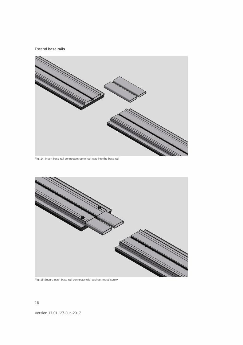
Extend base rails
Fig. 14: Insert base rail connectors up to half-way into the base rail
Fig. 15 Secure each base rail connector with a sheet-metal screw

17
Version 17.01, 27-Jun-2017
Base rail alignment
Fig. 16 Join the base rails together and screw in 2 more sheet-metal screws
Fig. 17 Align the base rails so that they are parallel and vertical.

18
Version 17.01, 27-Jun-2017
Important information:
On very uneven roofs, it can happen that the base rail rests on the roof covering.
In this case additional protection mats must be placed. Building protection mats can be ordered separately.
Fig. 18 Distance between base rails: module length + 20 mm or module length - 160 mm

19
Version 17.01, 27-Jun-2017
7.2 Third Base rail
In order not to exceed the permissible surface pressure of the roof insulation, a third base rail may be
necessary. The additional baserail with supports is placed cetrally under the modules. Module clamps are
not reqired here.
Fig. 19 Thrid base rail AeroFix10-S and 15-S
Fig. 20 Third base rail AeroFix10-EW
20
Version 17.01, 27-Jun-2017
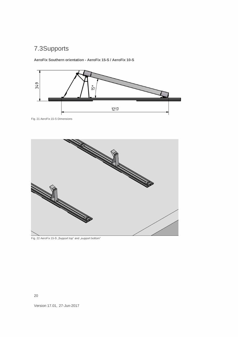
7.3 Supports
AeroFix Southern orientation - AeroFix 15-S / AeroFix 10-S
Fig. 21 AeroFix 15-S Dimensions
Fig. 22 AeroFix 15-S „Support top“ and „support bottom“
21
Version 17.01, 27-Jun-2017
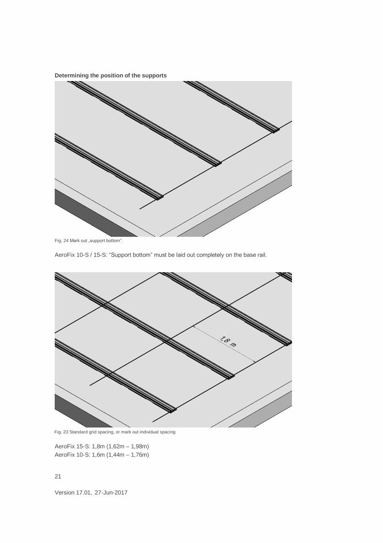
Determining the position of the supports
AeroFix 10-S / 15-S: “Support bottom” must be laid out completely on the base rail.
AeroFix 15-S: 1,8m (1,62m – 1,98m)
AeroFix 10-S: 1,6m (1,44m – 1,76m)
Fig. 24 Mark out „support bottom“.
Fig. 23 Standard grid spacing, or mark out individual spacing

22
Version 17.01, 27-Jun-2017
Fig. 25 Screw the „support bottom“ onto the base rail on the marking with screw M8x16
Fig. 26 Mounted „support bottom“

23
Version 17.01, 27-Jun-2017
Distance between supports AeroFix 15-S
Module width Distance x
950 mm 715 mm
960 mm 725 mm
970 mm 736 mm
980 mm 746 mm
990 mm 756 mm
1000 mm 767 mm
Tab. 3: AeroFix 15-S, Distance between „support top“ and „support bottom“
Fig. 27 AeroFix 15-S, Screw „support bottom“ onto the base rail at „x“ distance with 2 M8x16 screws

24
Version 17.01, 27-Jun-2017
Distance between supports AeroFix 10-S
Module width Distance x
950 mm 763 mm
960 mm 773 mm
970 mm 783 mm
980 mm 793 mm
990 mm 803 mm
1000 mm 813 mm
Tab. 4: AeroFix 10-S, Distance between „support top“ and „support bottom“
Fig. 28 AeroFix 10-S, Screw „support bottom“ onto the base rail at „x“ distance with 2 M8x16 screws

25
Version 17.01, 27-Jun-2017
Attaching the ballast rail
The number and position of the ballast rail is determined by the static calculations for the project.
See more at chapter “7.4”
Fig. 29 The ballast rail is attached directly in front of the „support top“ and secured onto the base rail with 2 M8x16
screws

26
Version 17.01, 27-Jun-2017
AeroFix East-west orientation - AeroFix 10-EW
Determining the position of the supports
Define the position of the „lower support“. The
distance from the leading edge of the base rail to
the „support bottom“ must be at least 1250 mm
when using a wind deflector.
Important information:
If you end with a wind plate you will need
the AeroFix 10-S “support top” instead
the AeroFi 10-EW “support top”
Define the position of the “lower support”.
The “support bottom” must be fully supported
on the base rail.
Fig. 31 AeroFix 10-EW with wind plate finish
Fig. 30 AeroFix 10-EW with module finish
Fig. 32 AeroFix 10 with wind deflector finish
Fig. 33 AeroFix 10 with module finish

27
Version 17.01, 27-Jun-2017
Fig. 35 Screw the “support bottom” into the base rail on the marking with screw M8x16
Fig. 34 Standard grid spacing 2.3 m

28
Version 17.01, 27-Jun-2017
Distance between supports
Module width Distance x
950 mm 763 mm
960 mm 773 mm
970 mm 783 mm
980 mm 793 mm
990 mm 803 mm
1000 mm 813 mm
Tab. 5: Distance between “support top” and “support bottom“
Fig. 36 Screw “supports top” onto the base rail at “x” distance with 2 M8x16 screws

29
Version 17.01, 27-Jun-2017
Attaching the ballast rail
The number and position of the ballast rail is determined by the static calculations for the project. For more
information on ballast please refer to chapter „7.4“.
Fig. 37 The ballast rail is attached directly in front of the „support top“ and secured onto the base rail with 2 M8x16
screws

30
Version 17.01, 27-Jun-2017
7.4 Ballast
Important information:
When adding ballast to the base rail it is not permitted to completely seal the space between the base rail
and the module with ballast stones!
Fig. 38 AeroFix 15-S, AeroFix 10-S ballast with ballast rail and base rail
Fig. 39 AeroFix 10-EW ballast with ballast rail and base rail

31
Version 17.01, 27-Jun-2017
Important information:
We recommend that you use stones with the following measurements (w x l x h):
NF 11,5 x 24 x 7,1 cm
2DF 11,5 x 24 x 11,3 cm
3DF 17,5 x 24 x 11,3 cm
Stone 40 x 40 x 4 cm
The ballast should always be placed under the module. The max. ballasting potential on the base rail is
and corresponds, in the above-mentioned blocks, the Aerofix 15-S (Aerofix 10-S / AeroFix 10-EW):
If the system has to be loaded with more than 42 kg (28 kg) per module a ballast rail is necessary.
The assignment of the ballast track should always be done from the outside inward. When using the
ballast stones recommended here, a maximum weighting of up to 120 kg/module is possible when the
ballast rail is used in combination with the base rail.
Important information:
When using alternative ballast rails (i.e. L-profiles) and alternative ballast materials (i.e. concrete slabs) the
adequate corrosion protection and frost resistance of materials is to ensure!
Fig. 40: Ballasting oft he base rail
Fig. 41: Assignment of ballast rail

32
Version 17.01, 27-Jun-2017
7.5 Snow load rail
The snow load rail for all mounting support is required, if the allowed snow load on the modules is exceed
in corner clamping. The snow load rail is inserted in the mountuing supports and is fixed with clips on the
module. The clips do not replace the module clamp. The installation instructions and maximum allowed
loads of the respective solar module manufacturers must be exactly kept.
Fig. 42 Snow load rail in the "support bottom"
Fig. 43 Snow load rail in the "support top"

33
Version 17.01, 27-Jun-2017
Important information:
The snow load rail can only be installed with the middle clamp G4 and at the end of the row with the EC
adapter. The clips of the sno load rail do not replace the module clamps.
Fig. 45 Snow load rail long with 2 clips and G4 middle clamp
Fig. 44 Short and long snow load rail

34
Version 17.01, 27-Jun-2017
7.6 Module assembly
The procedure for installing “AeroFix10-S / AeroFix 10-EW” is identical to that of „AeroFix 15“.
Fig. 47 The module must lie flat against the end stop on the “support top“ (with wind plate mounting)
Fig. 46 Insert the module into the “support top” and “support bottom“

35
Version 17.01, 27-Jun-2017
Ensure that a distance of 65 mm is maintained between the module frame and the rear panel of the upper
support. Beginning with the outer clamps, tighten the modules to a torque of 15 Nm. For this we
recommend a torque wrench with Torx bit size TX40.
Fig. 48 Module on the end stop and clamped
Fig. 49 Lay out the modules and attach using module clamps (in front “support top” without wind plate mounting)

36
Version 17.01, 27-Jun-2017
The middle and outer clamp are delivered pre-
assembled.
The middle clamp G3 covers a clamping area of
30-50 mm.
However the outer clamp G3 must be ordered for
each module height.
G3 Middle and outside clamp
The middle clamp G4 covers a clamping area of
33-46 mm.
The EC adapter is installed with the middle clamp
G4 or G3 and replaces the traditional outer clamp.
G4 middle clamp and EC adapter
Important information:
Depending on the height of the module frame, a different version of the outer clamp G3 will be required.
The EC adapter for G4 middle clamp covers only the frame sizes 33, 35, 38, 40, 45 and 46mm.
The tightening torque of the clamps must not exceed 15 Nm!
Do not use a ratchet or a wrench with high leverage as the maximum tightening torque could easily be
exceeded.
Please only use a Torx screwdriver with T-handle or cordless screwdrivers with the appropriate torque
settings.
The middle and outer clamps G3 can be inserted into the supports directly from above where required.
1. Insert 2. Press 3. Fixed
Fig. 50: Inserting the middle clamp G3

37
Version 17.01, 27-Jun-2017
The middle clamp G4 is pivoted from above into the support or introduced laterally, where it is needed.
The adaptor EC is clamped by the given frame height with the middle clamp G4 and substitutes thus the
end clamp.
Fig. 51 Pivoting the middle clamp G4
Fig. 52 EC adapter with middle clamp G4 Fig. 53 EC adapter frame hights

38
Version 17.01, 27-Jun-2017
7.7 Wind plate assembly
Beginning with the rear side of the left module row, mount the wind plate on the supports. Screw the left
side of the wind plate to the base rail with screw M8x16. Slide the wind deflector for the next module
sideways on the previously mounted plate and mount onto the next support. Ensure that the lateral tabs
clasp the wind plate. Screw both plates onto the base rail. Repeat process with the other wind plates in the
row.
The first and last wind plates in the module row or single wind plates have to be attached with a sheet-
metal screw to the support (Fig.57) .
For AeroFix 10-EW, wind plates and AeroFix 10S “support top” are only required on the modules if
the first/last row begins/ends with an “support top”
individual modules are omitted with a module field
Fig. 54 Mounted wind plate
Fig. 55 Wind plate assembly starting from the left

39
Version 17.01, 27-Jun-2017
Fig. 56 Wind plate assembly starting from the left
Fig. 57 Insert wind plate

40
Version 17.01, 27-Jun-2017
Fig. 58 Wind plate assembly
Fig. 59 Fixation wind plate

41
Version 17.01, 27-Jun-2017
7.8 Cable clip assembly
Fig. 61 assembly cable clip 90°
Fig. 60 assembly cable clip 0°

42
Version 17.01, 27-Jun-2017
08. System security device
For a roof inclination >3° it is an additional system security device necessary. With the anti-slip safety
device, the module arrays are connected to each other via the ridge. Alternatively, the anti-slip syftey
device can be attached at the building. The fastening to the building must be planned and statically tested
by the customer. The anti-slip safety device is then attached every second to fourth row. Damage to the
roof cladding from the anti-slip safety device can be prevented in the long-term through suitable measures
by the customer.
Mounting the anti-slip safety device. The perforated tape links the ground rails over the ridge.
Fig. 63 Longitudinally mounted anti-slip saftey device
Fig. 62 Cross-mounted anti-slip safety device

43
Version 17.01, 27-Jun-2017
Placement of the anti-slip device over the
ridge. The roof cladding must be protected
from any damage.
The perforated tape is connected to the
base rail with a M8x16 socket head screw.
The perforated tape is connected to the
base rail with at least two M8x16 socket
head screws.
Fig. 64: Ridge placement
Fig. 65: Base rail anti-slip security device cross connection
Fig. 66 Ground rail anti-slip security device longitudinal connection

44
Version 17.01, 27-Jun-2017
09. Final inspection
After completing the PV system inspect the screw and clamp connections. Check the entire structure for
strength and stability and check the roof cladding for damage.
It is advisable to document the completed system.

45
Version 17.01, 27-Jun-2017
10. Parts list
Image Product no. Description
AeroFix 10 / 15
Base rail with integrated building protection mat
6101100029 Base Rail G2, 800mm
6101100030 Base Rail G2, 1500mm
6101100031 Base Rail G2, 2200mm
6101100032
Base Rail G2, 3100mm
6101100033 Base Rail G2, 4200mm
6101100034 Base Rail G2, 5400mm
Base rail with integrated building protection mat foil-
laminated (ak)
6101100035 Base Rail ak G2, 800mm
6101100036 Base Rail ak G2, 1500mm
6101100037 Base Rail ak G2, 2200mm
6101100038 Base Rail ak G2, 3100mm
6101100039 Base Rail ak G2, 4300mm
6101100040 Base Rail ak G2, 5400mm

46
Version 17.01, 27-Jun-2017
Image Product no. Description
6101100041 Base rail connector
6101100022 Ballast rail
Middle clamp G3
6700400125 Middle clamp G3 30-50 mm
End clamp G3
6700400127 End clamp G3 31 mm
6700400164 End clamp G3 32 mm
6700400129 End clamp G3 33 mm
6700400130 End clamp G3 35 mm
6700400132 End clamp G3 38 mm
6700400134 End clamp G3 40 mm
6700400136 End clamp G3 42 mm
6700400138 End clamp G3 45 mm
6700400140 End clamp G3 46 mm
6700400142 End clamp G3 50 mm

47
Version 17.01, 27-Jun-2017
Image Product no. Description
6700400144 Middle clamp G4 33-46mm
6700400161 EC adapter 33-46mm
6900600010 Self-drilling-screw 4.8x19 – SW8
6900100012 Socket Cap Screw M8x16 A2 TX40
AeroFix 10 –S
6101100042 Support top
Also used in AeroFix 10-EW with wind plate beginning and
ending.
6101100043 Support bottom
Also used in AeroFix 10-EW with module beginning and
ending.
6101100016 Wind plate
Also used in AeroFix 10-EW with wind plate beginning and
ending.

48
Version 17.01, 27-Jun-2017
Image Product no. Description
AeroFix 10-EW
6101100044 Support top
Without windplate mounting
6101100045 Support bottom
SeroFix 15-S
6101100046 Support top
6101100047 Support bottom
6101100019 Wind plate

49
Version 17.01, 27-Jun-2017
Image Product no. Descriptionv
Optional
6101100020 Building protection mat
500x172x15 mm
6101100021 Building protection mat (ak), foil-laminated
500x172x15 mm
6101100025 Slide protection
Coil 10 m
- 25 mm width
- Ø 9 mm
6101100027 Cable clip 0°
6101100028 Cable clip 90°
6700200039 Clamp for equipotential bonding

50
Version 17.01, 27-Jun-2017
Tab. 6: Parts list, for illustration only
Image Product no. Description
Optional
6101100023 Assembling jig
for
- ground rail distance
- support distance
6101100024 Static friction measuring device
to determine the static friction coefficients
incl.:
- case
- dynamometer
6101100048 Snow load rail long G2
incl.:
– 2 clip
6101100049 Snow load rail short G2
incl.:
– 1 clip

51
Version 17.01, 27-Jun-2017
11. Appendix
11.1 Information about IBC AeroFix
Tightening torques of screw connections
The tightening torques of the screw connections used in the IBC AeroFix flat roof system should be
dimensioned in accordance with DIN ISO 3506. Due to the difficulty in determining the friction coefficients
in the external area, dimensioning in accordance with DIN ISO 3506 can prove difficult. We therefore
recommend the following tightening torques:
Screw connection Tightening torque
M8 (module clamp) 15 Nm
M8 (other) 10 Nm
Tab. 7: Tightenning torques
11.2 Maintenance instructions
In addition to the electrical inspections prescribed for the entire PV system, we recommend regular
inspection of the PV generator considering the following points.
Check:
the solar modules for damage and dirt
that all mechanical connections are firmly mounted (retightening screw joints)
the assembly system and module frame for mechanical damage from snow and ice loads
the roof drainage
the roof cladding for tightness
all electrical cables for damage (e.g. from animals)
all electrical plug and screw connections are secure and protected against accidental touching
If it becomes necessary to clean the modules, this must be done without chemical cleaning products and
using only clear water.
The modules can easily be replaced by removing the module cabling and releasing the corresponding
module clamps. Please observe the relevant safety requirements when doing this.

52
Version 17.01, 27-Jun-2017
11.3 IBC Aerofix Stiction Log
IBC AeroFix flat-roof system
Test record
Determination of stiction coefficients CUSTOMER INFORMATION
Name Phone
Company Mobile
Street / No. Fax
Post code/city E-mail
CONSTRUCTION PROJECT Customer
name Phone
Street / No. Mobile
Post code/city Fax
Com.: E-mail
TEST PROCEDURE
The test specimen (10 kg on IBC stiction gauge)
is placed onto the roof membrane with the
appropriate protective matting. After the defined
waiting period (around 30 seconds) has elapsed,
parallel force is applied centrally to the test
specimen using the tension spring, and then
measured using the spring scale. It is important
that the force be applied evenly. The maximum
force that can be applied before the test
specimen begins to move indicates the
coefficient of friction.
The tests are to be performed in accordance with the October 2004 edition of DIN EN ISO 8295, Plastics -
Films and sheeting - Determining coefficients of friction.
A total of 10 tests are to be carried out: five dry, five wet. The tests are to be distributed evenly across the roof
surface.
Visually dissimilar roof areas are to be tested separately from one another. The tests are to be repeated
accordingly.
Before testing begins, the roof membrane areas where measurements are being taken should be cleaned.
Static friction coefficient µ = F /G

53
Version 17.01, 27-Jun-2017
Sketch of roof structure (from top to bottom)
Date:
Time:
Temperature:
Dry Wet
Test No. Test
specimen weight
Measured force
µ Test
specimen weight
Measured force
µ
G (kg) F (kg) F / G G (kg) F (kg) F / G
1
2
3
4
5
Evaluation (based on lowest measured value)
µ =
Appendix:
Roof layout plan with measuring point locations / test procedures
Signature person in charge

54
Version 17.01, 27-Jun-2017
11.4 Checklist IBC AeroFix

55
Version 17.01, 27-Jun-2017

56
Version 17.01, 27-Jun-2017
12. Notes

57
Version 17.01, 27-Jun-2017
IBC SOLAR AG
Am Hochgericht 10
96231 Bad Staffelstein
Phone +49 (0) 9573-92 24 0
Fax +49 (0) 9573-92 24 111
info @ ibc-solar.de
www.ibc-solar.com


![IBC-LW [Large] (432V and 480V) IBC-LHW [Large High Rate ......p/n: P-164000541 Revision 04 IBC-LW [Large] (432V and 480V) IBC-LHW [Large High Rate] (432V and 480V) Installation Manual](https://img.pdfslide.net/doc/110x75/5e6875ee2288d344b302aa0a/ibc-lw-large-432v-and-480v-ibc-lhw-large-high-rate-pn-p-164000541.jpg)