Embed Size (px)
Citation preview

INSTALLATION INSTRUCTIONS
Read this manual before starting to work! This information is necessary for the safe and efficient operation of the equipment.
AUT SERIES SURGICAL LIGHTS
(STANDARD RADIAL ARM MODELS ONLY)
TEC-B-0078 REV308/28/14

COMPETENCY AND INSTALLATION REQUIREMENTSThis product is a Class 2 medical device that is subject to FDA Part 820 requirements. Installation can only take place by qualified and trained individuals. An Installation Qualification Report is required as proof of system operational validation prior to clinical use. Contact Skytron for installation needs.
Distributed by:
US - SKYTRON5085 Corporate Exchange Blvd. S.E.Grand Rapids, MI 49512 (616) 656-2900www.skytron.us
Manufactured by:DKK Dai-lchi Shomei Co., LTD32-26 Sakashita 1-ChomeItabash i-Ku, Tokyo 174-0043JAPAN
SKYTRON EUROPE BVFloresstraat 528022 AD ZwolleTHE NETHERLANDS
The base language for this document is ENGLISH. Any translations must be from the base language document.
Printed copies are not controlled documents.
Although current at the time of publication, SKYTRON'S policy of continuous development makes this manual subject to change without notice. If current manuals are required, contact your local SKYTRON representative or contact SKYTRON directly at the distribution addresses listed above.
Page 1
AURORA 3 INSTALL • REV3
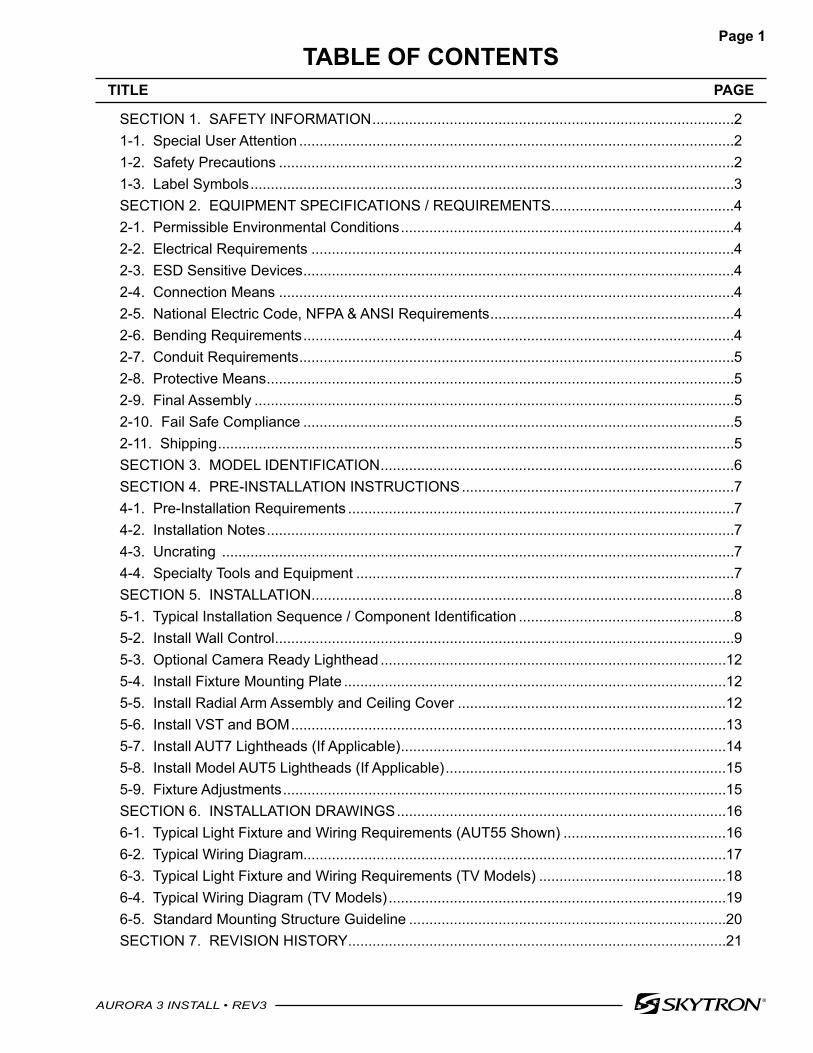
TABLE OF CONTENTSTITLE PAGE
SECTION 1. SAFETY INFORMATION .........................................................................................21-1. Special User Attention ...........................................................................................................21-2. Safety Precautions ................................................................................................................21-3. Label Symbols .......................................................................................................................3SECTION 2. EQUIPMENT SPECIFICATIONS / REQUIREMENTS .............................................42-1. Permissible Environmental Conditions ..................................................................................42-2. Electrical Requirements ........................................................................................................42-3. ESD Sensitive Devices ..........................................................................................................42-4. Connection Means ................................................................................................................42-5. National Electric Code, NFPA & ANSI Requirements ............................................................42-6. Bending Requirements ..........................................................................................................42-7. Conduit Requirements ...........................................................................................................52-8. Protective Means ...................................................................................................................52-9. Final Assembly ......................................................................................................................52-10. Fail Safe Compliance ..........................................................................................................52-11. Shipping ...............................................................................................................................5SECTION 3. MODEL IDENTIFICATION .......................................................................................6SECTION 4. PRE-INSTALLATION INSTRUCTIONS ...................................................................74-1. Pre-Installation Requirements ...............................................................................................74-2. Installation Notes ...................................................................................................................74-3. Uncrating ..............................................................................................................................74-4. Specialty Tools and Equipment .............................................................................................7SECTION 5. INSTALLATION ........................................................................................................85-1. Typical Installation Sequence / Component Identification .....................................................85-2. Install Wall Control .................................................................................................................95-3. Optional Camera Ready Lighthead .....................................................................................125-4. Install Fixture Mounting Plate ..............................................................................................125-5. Install Radial Arm Assembly and Ceiling Cover ..................................................................125-6. Install VST and BOM ...........................................................................................................135-7. Install AUT7 Lightheads (If Applicable) ................................................................................145-8. Install Model AUT5 Lightheads (If Applicable) .....................................................................155-9. Fixture Adjustments .............................................................................................................15SECTION 6. INSTALLATION DRAWINGS .................................................................................166-1. Typical Light Fixture and Wiring Requirements (AUT55 Shown) ........................................166-2. Typical Wiring Diagram........................................................................................................176-3. Typical Light Fixture and Wiring Requirements (TV Models) ..............................................186-4. Typical Wiring Diagram (TV Models) ...................................................................................196-5. Standard Mounting Structure Guideline ..............................................................................20SECTION 7. REVISION HISTORY .............................................................................................21
Page 2
AURORA 3 INSTALL • REV3
SECTION 1. SAFETY INFORMATION1-1. Special User AttentionThe procedures described in this manual will be performed by representatives of the owner (staff or contracted service), therefore it is the responsibility of the owner to ensure that all safety precautions are followed. Only qualified and trained individuals should attempt the installation of this product.
1-2. Safety PrecautionsThe following is a summary of DANGERS, WARNINGS, and CAUTIONS denoted in this manual. These precautions are found throughout the manual where they are applicable. Carefully read the manual before proceeding to operate or service the equipment.
DANGER
DANGER with the safety alert symbol, is used to indicate a hazardous situation that, if not avoided, will result in death or serious injury.
WARNING
WARNING with the safety alert symbol, is used to indicate a hazardous situation that, if not avoided, could result in death or serious injury.
To avoid the risk of electric shock, this equipment must only be connected to a supply mains with protective earth ground.
DO NOT remove lighthead when support arm is in down position. The BOM will be severely damaged and it may result in bodily injury.
CAUTION
CAUTION with the safety alert symbol, is used to indicate a hazardous situation that, if not avoided, could result in minor or moderate injury.
Connection of the fixture wires must be made using crimp connectors. Main terminal devices shall be so located or shielded that, should a wire of a stranded conductor escape when the conductors are fitted, there is no risk of accidental contact between live parts and accessible parts. Acceptable shielding methods include UL approved shrink tubing and electrical tape. DO NOT use damaged wire.
CAUTIONCAUTION without the safety alert symbol, is used to address practices not related to personal injury but with a possibility of damage to equipment.
This equipment is intended for use by healthcare professionals only. This equipment may cause radio interference or may disrupt the operation of nearby equipment. It may be necessary to take mitigation measures, such as re-orienting or relocating the lighthead or shielding the location.
This fixture requires that electrical connections are made by a licensed electrician in accordance with state, local, and national electrical codes using UL (Underwriters Laboratory) recognized materials.
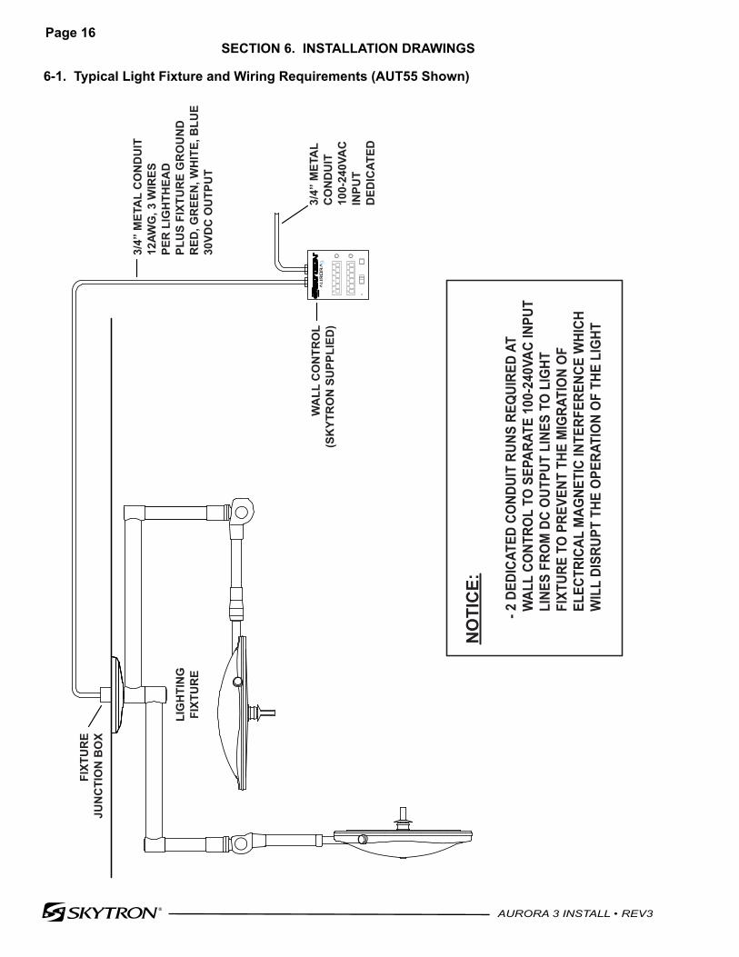
This fixture requires two (2) dedicated conduit raceways at the wall control to separate the 100-240VAC facility supply lines from the DC supply lines to the lighting fixture. Failure to observe this requirement will allow the migration of electrical magnetic interference and will disrupt the operation of the lights.
Page 3
AURORA 3 INSTALL • REV3
CAUTION (CONT'D)
This fixture requires a properly circuit protected, appropriately sized, dedicated circuit. An isolated power supply circuit must be protected by an appropriately sized double pole, single throw circuit breaker.
SKYTRON surgical lights are packaged in special containers designed to prevent damage from vibration or shock. Always use SKYTRON supplied containers for shipment.
Aurora 3 lightheads operate on DC VOLTAGE. The PC boards are susceptible to static charges even when not powered. Pay close attention to wiring diagrams, wire labeling and color
codes. Wires must remain separate and not touch any other wires or metal parts. Incorrect wiring may result in incorrect polarity being supplied to the lighthead. This WILL DAMAGE internal circuitry and components VOIDING WARRANTY.
The mounting plate must be accurately leveled within 0.1° to prevent lighthead drift.
To prevent support arm damage, the longer screws must be installed in the holes towards the lighthead.
NOTICE
Indicates important information not related to personal injury.
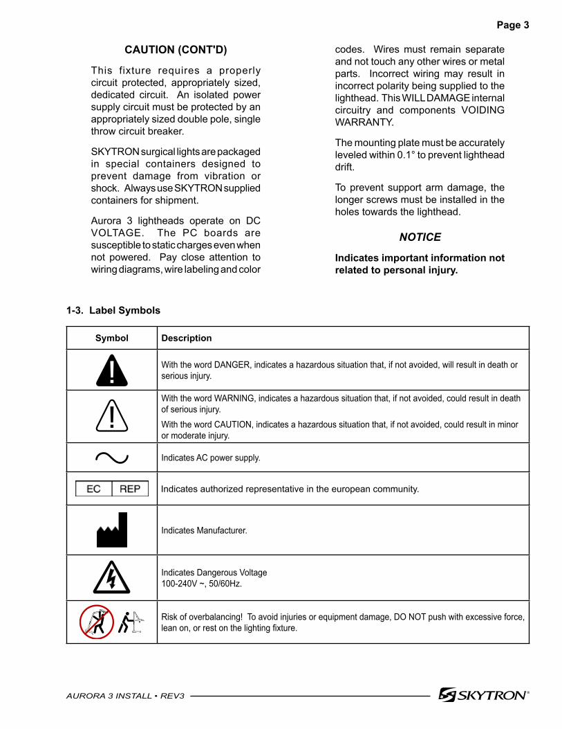
1-3. Label Symbols
Symbol Description
With the word DANGER, indicates a hazardous situation that, if not avoided, will result in death or serious injury.
With the word WARNING, indicates a hazardous situation that, if not avoided, could result in death of serious injury.With the word CAUTION, indicates a hazardous situation that, if not avoided, could result in minor or moderate injury.
Indicates AC power supply.
Indicates authorized representative in the european community.
Indicates Manufacturer.
Indicates Dangerous Voltage 100-240V ~, 50/60Hz.
Risk of overbalancing! To avoid injuries or equipment damage, DO NOT push with excessive force, lean on, or rest on the lighting fixture.

Page 4
AURORA 3 INSTALL • REV3
SECTION 2. EQUIPMENT SPECIFICATIONS / REQUIREMENTS
CAUTIONThis equipment is intended for use by healthcare professionals only. This equipment may cause radio interference or may disrupt the operation of nearby equipment. It may be necessary to take mitigation measures, such as re-orienting or relocating the lighthead or shielding the location.
2-1. Permissible Environmental Conditions
a. During Transport and Storage (in Original Packaging Materials)• Ambient Temperature: 14° to 140° F (-10 to 60 °C)• Relative Humidity: 10% to 85% (No Condensation)• Atmospheric Pressure: 14 to 31 inHg (500 to 1060 hPa)
b. During Use - For Dry Locations• Ambient Temperature: 60° to 85° F (15 to 30 °C)• Relative Humidity: 30% to 60% (No Condensation)• Atmospheric Pressure: 20.7 to 31.3 inHg (700 to 1060 hPa)
2-2. Electrical RequirementsCAUTION
This fixture requires that electrical connections are made by a licensed electrician in accordance with state, local, and national electrical codes using UL (Underwriters Laboratory) recognized materials.
DO NOT turn on main power to fixture until all lightheads are installed, connections are complete, and the fixture has been reviewed by a SKYTRON representative.ELECTRICAL HAZARDS EXIST!Exercise caution when working on this fixture, the installation of this fixture must be made only by qualified and authorized personnel familiar with the essential knowledge and techniques.
2-3. ESD Sensitive DevicesWhen installing devices with electronic circuit boards (e.g., lightheads, wall control units), appropriate precautions should be taken to prevent damage caused by electrostatic discharge (ESD). These precautions include as a minimum, the use of an ESD wrist strap that is properly connected to an ESD ground.
2-4. Connection Means
CAUTION
Connection of the fixture wires must be made using crimp connectors. Main terminal devices shall be so located or shielded that, should a wire of a stranded conductor escape when the conductors are fitted, there is no risk of accidental contact between live parts and accessible parts. Acceptable shielding methods include UL approved shrink tubing and electrical tape. DO NOT use damaged wire.
2-5. National Electric Code, NFPA & ANSI RequirementsThe installation of connecting cords between equipment parts shall meet the requirements of the National Electrical Code, ANSI/NFPA70, IEC 60601-1 and all local codes, as applicable.
2-6. Bending RequirementsConnection leads shall be constructed in such a manner that moveable leads in normal use are not bent around a radius of less than five times the outer diameter of the lead concerned. Avoid conditions employing severe bends to ensure the integrity of conductors.
Page 5
AURORA 3 INSTALL • REV3
2-7. Conduit RequirementsCAUTION
This fixture requires two (2) dedicated conduit raceways at the wall control to separate the 100-240VAC facility supply lines from the DC supply lines to the lighting fixture. Failure to observe this requirement will allow the migration of electrical magnetic interference and will disrupt the operation of the lights.
Use of approved metal conduit shall be employed throughout the fixture's wiring circuit where applicable.
2-8. Protective Means
WARNING
To avoid the risk of electric shock, this equipment must only be connected to a supply mains with protective earth ground.
CAUTION
This fixture requires a properly circuit protected, appropriately sized, dedicated circuit. An isolated power supply circuit must be protected by an appropriately sized double pole, single throw circuit breaker.
Proper performance and safety of this fixture can only be achieved by an adequate grounding system. Fixture ground must be a dedicated ground point ultimately bonded to the facilities grounding system to prevent the migration of electrical interference generated by other devices.
2-9. Final AssemblyAll installations of SKYTRON surgical lights should be under the direct supervision of a SKYTRON authorized representative.Prior to the fixture being placed in service, the SKYTRON authorized representative must initialize the fixture and complete the installation report.To maintain product warranty and performance, this product requires routine service. Contact your SKYTRON representative for factory service or preventive maintenance contracts.
2-10. Fail Safe ComplianceIn order for dual or triple lighthead systems to maintain fail safe compliance, a battery back up (UPS) or generator back up power system must be provided in the mains wiring prior to the wall control which will restore power in five (5) seconds or less.
NOTICE
Fail safe devices are not supplied by SKYTRON.
2-11. ShippingCAUTION
SKYTRON surgical lights are packaged in special containers designed to prevent damage from vibration or shock. Always use SKYTRON supplied containers for shipment.
Page 6
AURORA 3 INSTALL • REV3
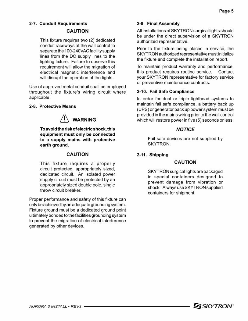
SECTION 3. MODEL IDENTIFICATION(Standard Radial Arm Configurations)
MODEL AUT5, AUT5TV 1 - 24" (610mm) Diameter Lighthead
MODEL AUT55, AUT5TV5, AUT55TV 2 - 24" (610mm) Diameter Lightheads
AUT5 AUT7
MODEL AUT75, AUT7TV5, AUT75TV 1 - 30" (762mm) Diameter Lighthead 1 - 24" (610mm) Diameter Lighthead
MODEL AUT7, AUT7TV 1 - 30" (762mm) Diameter Lighthead
MODEL AUT555, AUT55TV5, AUT555TV 3 - 24" (610mm) Diameter Lightheads
AUT5 AUT5 AUT7
MODEL AUT575, AUT57TV5, AUT575TV 1 - 30" (762mm) Diameter Lighthead
2 - 24" (610mm) Diameter Lightheads
Page 7
AURORA 3 INSTALL • REV3
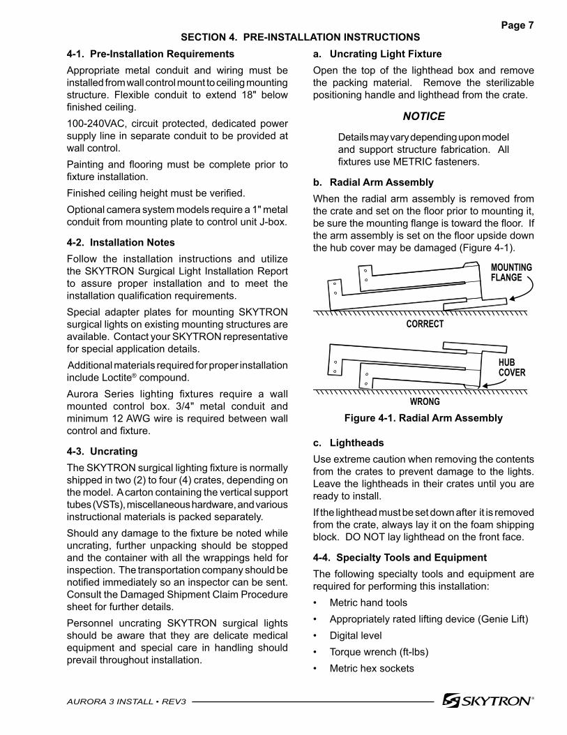
SECTION 4. PRE-INSTALLATION INSTRUCTIONSa. Uncrating Light FixtureOpen the top of the lighthead box and remove the packing material. Remove the sterilizable positioning handle and lighthead from the crate.
NOTICE
Details may vary depending upon model and support structure fabrication. All fixtures use METRIC fasteners.
b. Radial Arm AssemblyWhen the radial arm assembly is removed from the crate and set on the floor prior to mounting it, be sure the mounting flange is toward the floor. If the arm assembly is set on the floor upside down the hub cover may be damaged (Figure 4-1).
MOUNTING FLANGE
CORRECT
WRONG
HUBCOVER
Figure 4-1. Radial Arm Assembly
c. LightheadsUse extreme caution when removing the contents from the crates to prevent damage to the lights. Leave the lightheads in their crates until you are ready to install.If the lighthead must be set down after it is removed from the crate, always lay it on the foam shipping block. DO NOT lay lighthead on the front face.
4-4. Specialty Tools and EquipmentThe following specialty tools and equipment are required for performing this installation:• Metric hand tools• Appropriately rated lifting device (Genie Lift)• Digital level• Torque wrench (ft-lbs)• Metric hex sockets
4-1. Pre-Installation RequirementsAppropriate metal conduit and wiring must be installed from wall control mount to ceiling mounting structure. Flexible conduit to extend 18" below finished ceiling.100-240VAC, circuit protected, dedicated power supply line in separate conduit to be provided at wall control.Painting and flooring must be complete prior to fixture installation.Finished ceiling height must be verified.Optional camera system models require a 1" metal conduit from mounting plate to control unit J-box.
4-2. Installation NotesFollow the installation instructions and utilize the SKYTRON Surgical Light Installation Report to assure proper installation and to meet the installation qualification requirements.Special adapter plates for mounting SKYTRON surgical lights on existing mounting structures are available. Contact your SKYTRON representative for special application details. Additional materials required for proper installation include Loctite® compound.Aurora Series lighting fixtures require a wall mounted control box. 3/4" metal conduit and minimum 12 AWG wire is required between wall control and fixture.
4-3. Uncrating The SKYTRON surgical lighting fixture is normally shipped in two (2) to four (4) crates, depending on the model. A carton containing the vertical support tubes (VSTs), miscellaneous hardware, and various instructional materials is packed separately.Should any damage to the fixture be noted while uncrating, further unpacking should be stopped and the container with all the wrappings held for inspection. The transportation company should be notified immediately so an inspector can be sent. Consult the Damaged Shipment Claim Procedure sheet for further details.Personnel uncrating SKYTRON surgical lights should be aware that they are delicate medical equipment and special care in handling should prevail throughout installation.
Page 8
AURORA 3 INSTALL • REV3
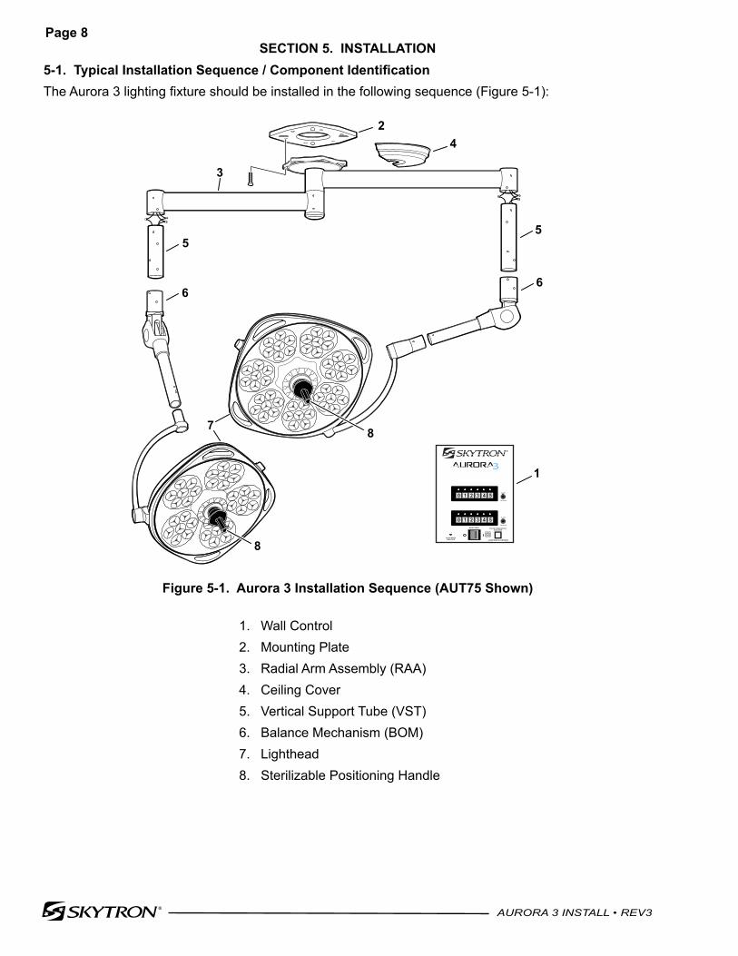
5-1. Typical Installation Sequence / Component IdentificationThe Aurora 3 lighting fixture should be installed in the following sequence (Figure 5-1):
40,000 HOURINDICATOR
COLOR TEMPERATUREINDICATOR
4,500K WHEN ILLUMINATED
MAIN POWER
2A, 250V
Fast Acting
2A, 250V
Fast Acting
0 1 2 3 4 5
0 1 2 3 4 5
1
3
4
55
2
87
66
8
Figure 5-1. Aurora 3 Installation Sequence (AUT75 Shown)
1. Wall Control2. Mounting Plate3. Radial Arm Assembly (RAA)4. Ceiling Cover5. Vertical Support Tube (VST)6. Balance Mechanism (BOM)7. Lighthead8. Sterilizable Positioning Handle
SECTION 5. INSTALLATION

Page 9
AURORA 3 INSTALL • REV3
5-2. Install Wall ControlNOTICE
3/4" metal conduit and minimum 12AWG wire (3 wires per lighthead plus fixture ground) is required between wall control and fixture. Flexible conduit should extend 18" below finished ceiling.
NOTICE
Separate dedicated conduit required for 100-240VAC supply lines to wall control.
All wiring to be in accordance with local, state and national electrical codes.
a. Remove the front panel assembly from the wall control box for ease in wire connection. Remove the (4) screws. Set the front panel assembly aside.b. Install the wall control box enclosure as desired for the application (surface or recessed mount) as shown in the wall control illustration (Figure 5-2).c. Attach recess mount flange if required for recessed applications (Figure 5-2).
NOTICE
Room placement of the wall control will vary by application. Always follow current standards from the NFPA (National Fire Protection Agency), NEC (National Electrical Code) and IEC (International Electrotechnical Commission) for proper compliance.
The selection of anchorage fasteners shall be determined by the engineer of record and will vary by application. The selected fasteners must not interfere with wall control components.
Seismic applications require the use of approved fasteners.
CAUTIONAurora 3 lightheads operate on DC VOLTAGE. The PC boards are susceptible to static charges even when not powered. Pay close attention to wiring diagrams, wire labeling and color codes. Wires must remain separate and not touch any other wires or metal parts. Incorrect wiring may result in incorrect polarity being supplied to the lighthead. This WILL DAMAGE internal circuitry and components VOIDING WARRANTY.
d. Connect the electrical conductors from front face plate assembly to the wiring from the fixture. Observe wire markings and colors. Avoid undue stress on conductors and internal components.
CAUTION
Connection of the fixture wires must be made using crimp connectors. Main terminal devices shall be so located or shielded that, should a wire of a stranded conductor escape when the conductors are fitted, there is no risk of accidental contact between live parts and accessible parts. Acceptable shielding methods include UL approved shrink tubing and electrical tape.
e. Make electrical connections using approved crimp connectors. Observe wire markings and colors (Figure 5-3).f. Attach the front panel assembly using the (4) screws removed in Step a. Use care to avoid pinching conductors and creating excessive bends in wiring.
Page 10
AURORA 3 INSTALL • REV3
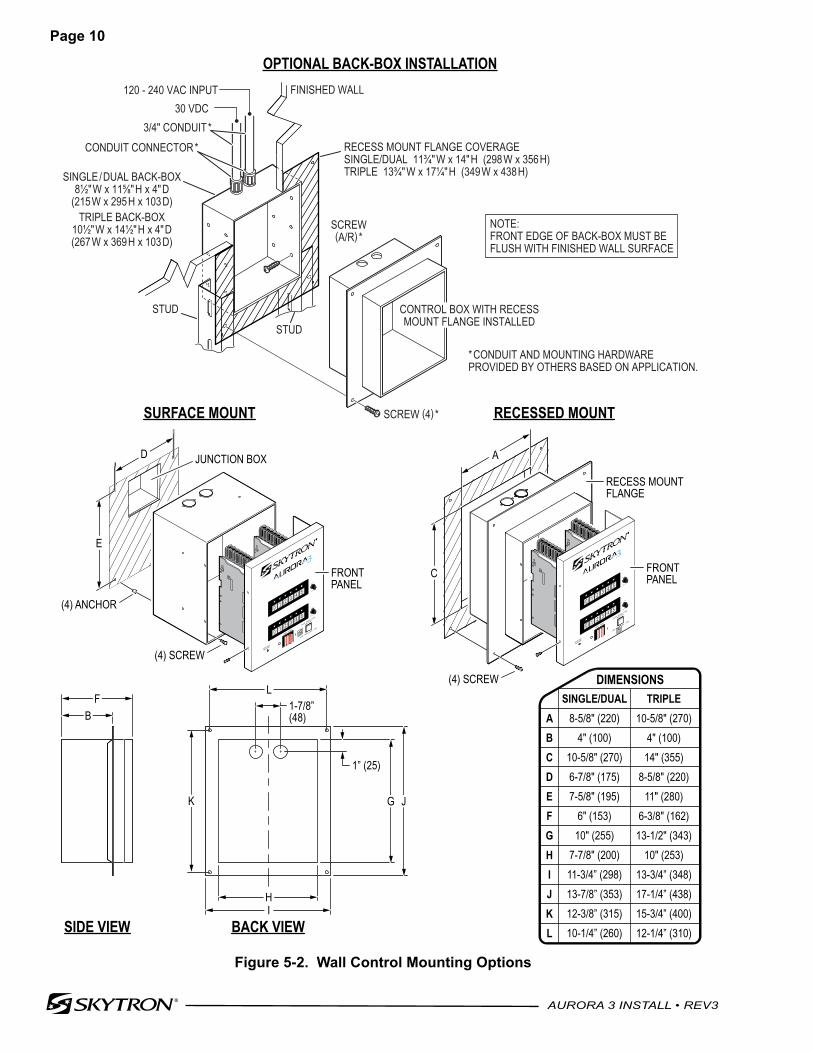
OPTIONAL BACK-BOX INSTALLATION
20,000 HOUR
INDIC ATOR
COLOR TEMPER ATURE
INDIC ATOR
4,500K WHEN ILLUMINATED
MAIN POWER
2A, 250V
Fast Acting
2A, 250V
Fast Acting
0 1 2 3 4 5
0 1 2 3 4 5
40,000 HOUR
INDICATOR
COLOR TEMPER ATURE
INDIC ATOR
4,500K WHEN ILLUMINATED
MAIN POWER
2A, 250V
Fast Acting
2A, 250V
Fast Acting
0 1 2 3 4 5
0 1 2 3 4 5
(4) SCREW
RECESS MOUNTFLANGE
FRONTPANELC
A
40,000 HOUR
INDICATOR
COLOR TEMPER ATURE
INDIC ATOR
4,500K WHEN ILLUMINATED
MAIN POWER
2A, 250V
Fast Acting
2A, 250V
Fast Acting
0 1 2 3 4 5
0 1 2 3 4 5
FRONTPANEL
(4) SCREW
JUNCTION BOX
(4) ANCHOR
D
E
RECESSED MOUNTSURFACE MOUNT
FB
SIDE VIEW BACK VIEW
SINGLE/DUAL8-5/8" (220)
4" (100)10-5/8" (270)6-7/8" (175)7-5/8" (195)
6" (153)10" (255)
7-7/8" (200)11-3/4” (298)13-7/8” (353)12-3/8” (315)10-1/4” (260)
TRIPLE10-5/8" (270)
4" (100)14" (355)
8-5/8" (220)11" (280)
6-3/8" (162)13-1/2" (343)
10" (253)13-3/4” (348)17-1/4” (438)15-3/4” (400)12-1/4” (310)
ABCDEFGHIJKL
1” (25)
1-7/8”(48)
K
L
HI
G J
DIMENSIONS
NOTE:FRONT EDGE OF BACK-BOX MUST BEFLUSH WITH FINISHED WALL SURFACE
SCREW (4) *
RECESS MOUNT FLANGE COVERAGESINGLE/DUAL 11¾"W x 14"H (298W x 356H)TRIPLE 13¾"W x 17¼"H (349W x 438H)SINGLE/DUAL BACK-BOX
8½"W x 11⅝"H x 4"D(215W x 295H x 103D)
TRIPLE BACK-BOX10½"W x 14½"H x 4"D(267W x 369H x 103D)
3/4" CONDUIT*
FINISHED WALL
CONTROL BOX WITH RECESSMOUNT FLANGE INSTALLED
CONDUIT CONNECTOR*
30 VDC120 - 240 VAC INPUT
STUD
STUD
SCREW(A/R)*
*CONDUIT AND MOUNTING HARDWAREPROVIDED BY OTHERS BASED ON APPLICATION.
Figure 5-2. Wall Control Mounting Options
Page 11
AURORA 3 INSTALL • REV3
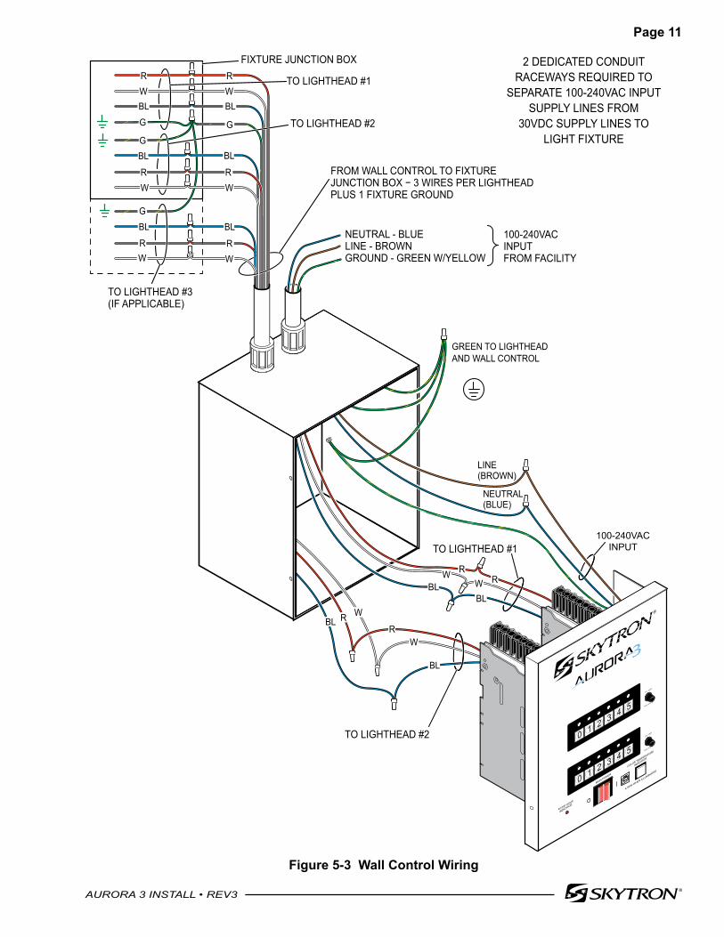
Figure 5-3 Wall Control Wiring
40,000 HOUR
INDICATOR
COLOR TEMPERATURE
INDICATOR
4,500K WHEN ILLUMINATED
MAIN POWER
2A, 250V
Fast Acting
2A, 250V
Fast Acting
0 1 2 3 4 5
0 1 2 3 4 5
TO LIGHTHEAD #2
TO LIGHTHEAD #1
NEUTRAL - BLUE LINE - BROWN GROUND - GREEN W/YELLOW
FROM WALL CONTROL TO FIXTUREJUNCTION BOX − 3 WIRES PER LIGHTHEADPLUS 1 FIXTURE GROUND
100-240VACINPUTFROM FACILITY
TO LIGHTHEAD #2
TO LIGHTHEAD #1
FIXTURE JUNCTION BOXRW
BL
RW
BL
RR
BL
W
WBL
RR
BLBLW
W
2 DEDICATED CONDUITRACEWAYS REQUIRED TO
SEPARATE 100-240VAC INPUTSUPPLY LINES FROM
30VDC SUPPLY LINES TOLIGHT FIXTURE
GREEN TO LIGHTHEADAND WALL CONTROL
BL BL
TO LIGHTHEAD #3(IF APPLICABLE)
G
G
R
BLG
R
G
R
BL
100-240VAC INPUT
NEUTRAL (BLUE)
LINE(BROWN)
WR
W W
W
Page 12
AURORA 3 INSTALL • REV3
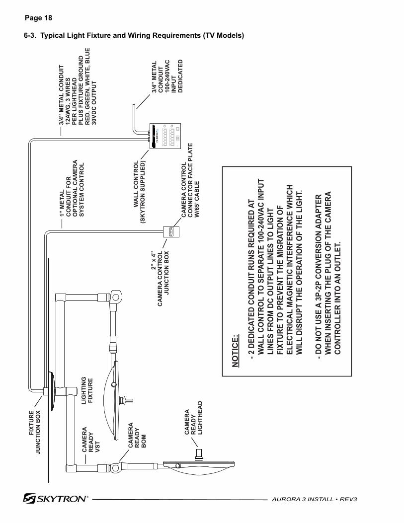
5-3. Optional Camera Ready LightheadThe optional camera ready lighthead system includes a connector faceplate with a 65 ft. cable that connects to the light fixture junction box.The faceplate is mounted in a 2" x 4" junction box and the cable is run through a 1" metal conduit to the light fixture junction box. D-sub 9-pin connectors are provided for cable connection at the fixture junction box and at the RAA/VST connection point.The camera ready lighthead must be installed with the corresponding camera ready BOM and VST. Refer to AUT TV fixture diagrams (Sections 6-3 and 6-4).
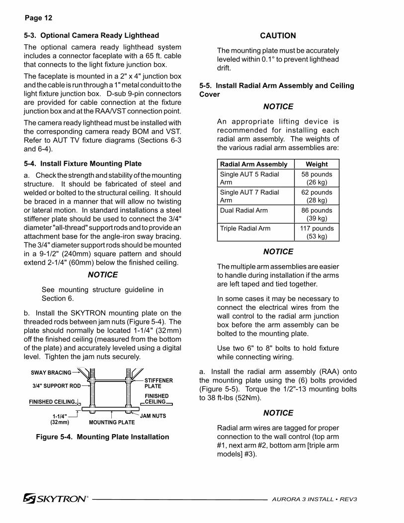
5-4. Install Fixture Mounting Platea. Check the strength and stability of the mounting structure. It should be fabricated of steel and welded or bolted to the structural ceiling. It should be braced in a manner that will allow no twisting or lateral motion. In standard installations a steel stiffener plate should be used to connect the 3/4" diameter "all-thread" support rods and to provide an attachment base for the angle-iron sway bracing. The 3/4" diameter support rods should be mounted in a 9-1/2" (240mm) square pattern and should extend 2-1/4" (60mm) below the finished ceiling.
NOTICE
See mounting structure guideline in Section 6.
b. Install the SKYTRON mounting plate on the threaded rods between jam nuts (Figure 5-4). The plate should normally be located 1-1/4" (32mm) off the finished ceiling (measured from the bottom of the plate) and accurately leveled using a digital level. Tighten the jam nuts securely.
FINISHED CEILING
3/4" SUPPORT ROD
SWAY BRACINGSTIFFENERPLATE
JAM NUTSMOUNTING PLATE
1-1/4"(32mm)
FINISHEDCEILING
Figure 5-4. Mounting Plate Installation
CAUTION
The mounting plate must be accurately leveled within 0.1° to prevent lighthead drift.
5-5. Install Radial Arm Assembly and Ceiling Cover
NOTICE
An appropriate lifting device is recommended for installing each radial arm assembly. The weights of the various radial arm assemblies are:
Radial Arm Assembly WeightSingle AUT 5 Radial Arm
58 pounds (26 kg)
Single AUT 7 Radial Arm
62 pounds (28 kg)
Dual Radial Arm 86 pounds (39 kg)
Triple Radial Arm 117 pounds (53 kg)
NOTICE
The multiple arm assemblies are easier to handle during installation if the arms are left taped and tied together.
In some cases it may be necessary to connect the electrical wires from the wall control to the radial arm junction box before the arm assembly can be bolted to the mounting plate.
Use two 6" to 8" bolts to hold fixture while connecting wiring.
a. Install the radial arm assembly (RAA) onto the mounting plate using the (6) bolts provided (Figure 5-5). Torque the 1/2"-13 mounting bolts to 38 ft-lbs (52Nm).
NOTICE
Radial arm wires are tagged for proper connection to the wall control (top arm #1, next arm #2, bottom arm [triple arm models] #3).
Page 13
AURORA 3 INSTALL • REV3
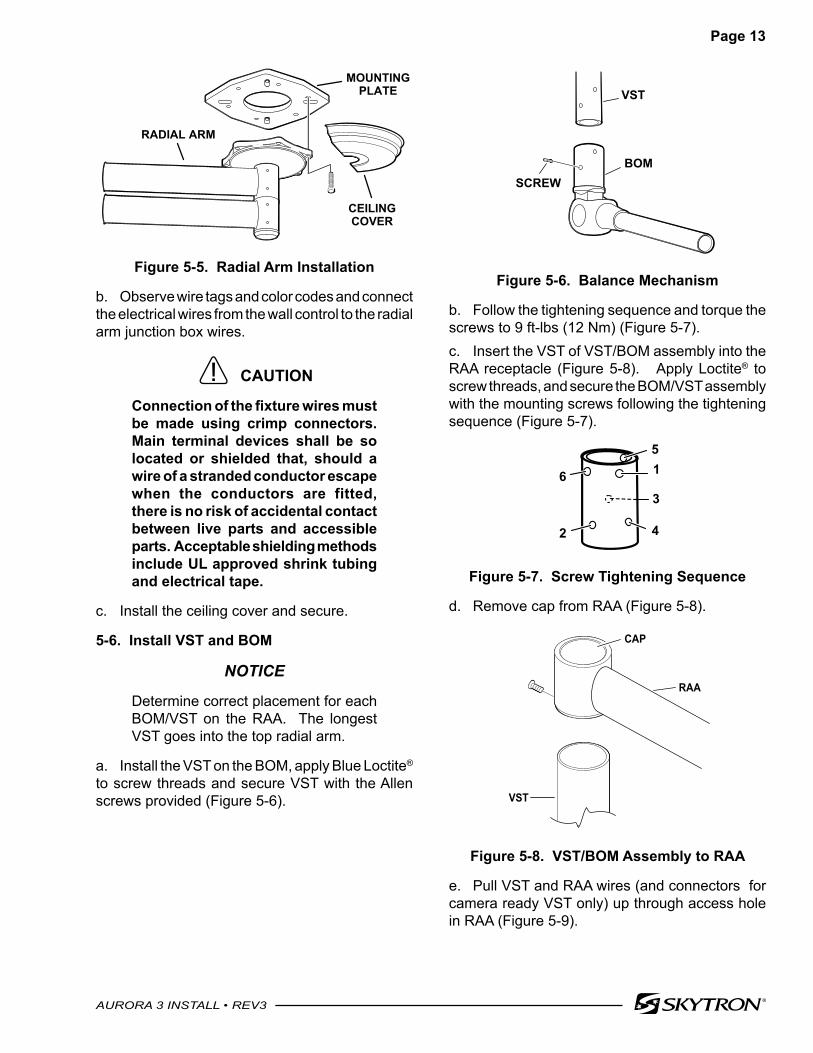
VST
BOMSCREW
Figure 5-6. Balance Mechanism
b. Follow the tightening sequence and torque the screws to 9 ft-lbs (12 Nm) (Figure 5-7).c. Insert the VST of VST/BOM assembly into the RAA receptacle (Figure 5-8). Apply Loctite® to screw threads, and secure the BOM/VST assembly with the mounting screws following the tightening sequence (Figure 5-7).
51
3
42
6
Figure 5-7. Screw Tightening Sequence
d. Remove cap from RAA (Figure 5-8).
RAA
VST
CAP
Figure 5-8. VST/BOM Assembly to RAA
e. Pull VST and RAA wires (and connectors for camera ready VST only) up through access hole in RAA (Figure 5-9).
RADIAL ARM
CEILINGCOVER
MOUNTINGPLATE
Figure 5-5. Radial Arm Installation
b. Observe wire tags and color codes and connect the electrical wires from the wall control to the radial arm junction box wires.
CAUTION
Connection of the fixture wires must be made using crimp connectors. Main terminal devices shall be so located or shielded that, should a wire of a stranded conductor escape when the conductors are fitted, there is no risk of accidental contact between live parts and accessible parts. Acceptable shielding methods include UL approved shrink tubing and electrical tape.
c. Install the ceiling cover and secure.
5-6. Install VST and BOM
NOTICE
Determine correct placement for each BOM/VST on the RAA. The longest VST goes into the top radial arm.
a. Install the VST on the BOM, apply Blue Loctite® to screw threads and secure VST with the Allen screws provided (Figure 5-6).
Page 14
AURORA 3 INSTALL • REV3
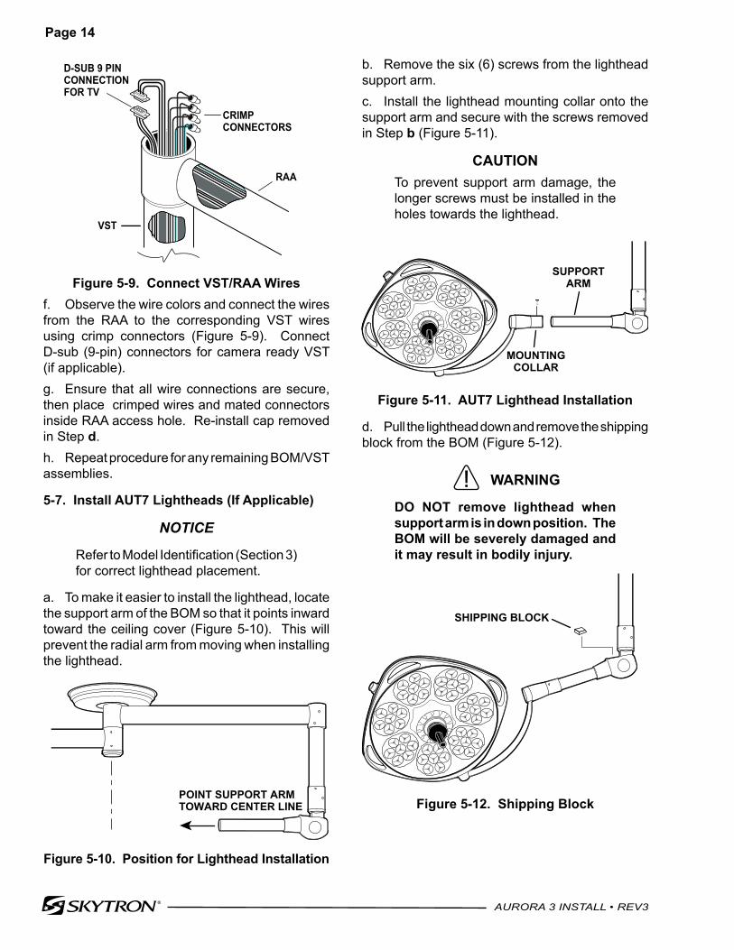
b. Remove the six (6) screws from the lighthead support arm.c. Install the lighthead mounting collar onto the support arm and secure with the screws removed in Step b (Figure 5-11).
CAUTIONTo prevent support arm damage, the longer screws must be installed in the holes towards the lighthead.
SUPPORTARM
MOUNTINGCOLLAR
Figure 5-11. AUT7 Lighthead Installation
d. Pull the lighthead down and remove the shipping block from the BOM (Figure 5-12).
WARNING
DO NOT remove lighthead when support arm is in down position. The BOM will be severely damaged and it may result in bodily injury.
SHIPPING BLOCK
Figure 5-12. Shipping Block
RAA
VST
CRIMPCONNECTORS
D-SUB 9 PINCONNECTIONFOR TV
Figure 5-9. Connect VST/RAA Wiresf. Observe the wire colors and connect the wires from the RAA to the corresponding VST wires using crimp connectors (Figure 5-9). Connect D-sub (9-pin) connectors for camera ready VST (if applicable).g. Ensure that all wire connections are secure, then place crimped wires and mated connectors inside RAA access hole. Re-install cap removed in Step d.h. Repeat procedure for any remaining BOM/VST assemblies.
5-7. Install AUT7 Lightheads (If Applicable)
NOTICE
Refer to Model Identification (Section 3)for correct lighthead placement.
a. To make it easier to install the lighthead, locate the support arm of the BOM so that it points inward toward the ceiling cover (Figure 5-10). This will prevent the radial arm from moving when installing the lighthead.
POINT SUPPORT ARMTOWARD CENTER LINE
Figure 5-10. Position for Lighthead Installation
Page 15
AURORA 3 INSTALL • REV3
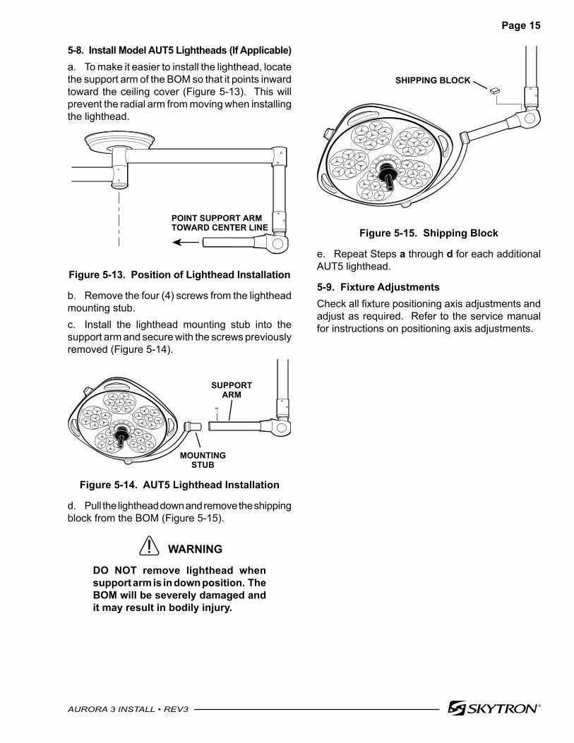
5-8. Install Model AUT5 Lightheads (If Applicable)a. To make it easier to install the lighthead, locate the support arm of the BOM so that it points inward toward the ceiling cover (Figure 5-13). This will prevent the radial arm from moving when installing the lighthead.
POINT SUPPORT ARMTOWARD CENTER LINE
Figure 5-13. Position of Lighthead Installation
b. Remove the four (4) screws from the lighthead mounting stub.c. Install the lighthead mounting stub into the support arm and secure with the screws previously removed (Figure 5-14).
SUPPORTARM
MOUNTINGSTUB
Figure 5-14. AUT5 Lighthead Installation
d. Pull the lighthead down and remove the shipping block from the BOM (Figure 5-15).
WARNING
DO NOT remove lighthead when support arm is in down position. The BOM will be severely damaged and it may result in bodily injury.
SHIPPING BLOCK
Figure 5-15. Shipping Block
e. Repeat Steps a through d for each additional AUT5 lighthead.
5-9. Fixture AdjustmentsCheck all fixture positioning axis adjustments and adjust as required. Refer to the service manual for instructions on positioning axis adjustments.
Page 16
AURORA 3 INSTALL • REV3
6-1. Typical Light Fixture and Wiring Requirements (AUT55 Shown)
- 2 D
EDIC
ATED
CO
NDUI
T RU
NS R
EQUI
RED
AT W
ALL
CONT
ROL
TO S
EPAR
ATE
100-
240V
AC IN
PUT
LIN
ES F
ROM
DC
OUT
PUT
LINE
S TO
LIG
HT F
IXTU
RE T
O P
REVE
NT T
HE M
IGRA
TIO
N O
F E
LECT
RICA
L M
AGNE
TIC
INTE
RFER
ENCE
WHI
CH W
ILL
DISR
UPT
THE
OPE
RATI
ON
OF
THE
LIG
HT
3/4”
MET
AL
CO
ND
UIT
100-
240V
AC
INPU
TD
EDIC
ATED
3/4”
MET
AL
CO
ND
UIT
12AW
G, 3
WIR
ESPE
R L
IGH
THEA
DPL
US
FIXT
UR
E G
RO
UN
DR
ED, G
REE
N, W
HIT
E, B
LUE
30VD
C O
UTP
UT
WA
LL C
ON
TRO
L(S
KYT
RO
N S
UPP
LIED
)
FIXT
UR
EJU
NC
TIO
N B
OX
LIG
HTI
NG
FIXT
UR
E
NO
TIC
E:
SECTION 6. INSTALLATION DRAWINGS
Page 17
AURORA 3 INSTALL • REV3
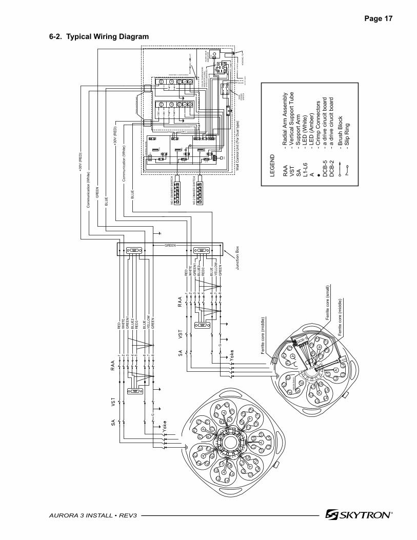
6-2. Typical Wiring Diagram
BROWNBLUE
.........
.........
.........
.........
Page 18
AURORA 3 INSTALL • REV3
6-3. Typical Light Fixture and Wiring Requirements (TV Models)
- 2 D
EDIC
ATED
CO
NDUI
T RU
NS R
EQUI
RED
AT W
ALL
CONT
ROL
TO S
EPAR
ATE
100-
240V
AC IN
PUT
LIN
ES F
ROM
DC
OUT
PUT
LINE
S TO
LIG
HT F
IXTU
RE T
O P
REVE
NT T
HE M
IGRA
TIO
N O
F E
LECT
RICA
L M
AGNE
TIC
INTE
RFER
ENCE
WHI
CH W
ILL
DISR
UPT
THE
OPE
RATI
ON
OF
THE
LIG
HT.
- DO
NO
T US
E A
3P-2
P CO
NVER
SIO
N AD
APTE
R W
HEN
INSE
RTIN
G T
HE P
LUG
OF
THE
CAM
ERA
CO
NTRO
LLER
INTO
AN
OUT
LET.
3/4”
MET
AL
CO
ND
UIT
100-
240V
AC
INPU
TD
EDIC
ATED
3/4”
MET
AL
CO
ND
UIT
12AW
G, 3
WIR
ESPE
R L
IGH
THEA
DPL
US
FIXT
UR
E G
RO
UN
DR
ED, G
REE
N, W
HIT
E, B
LUE
30VD
C O
UTP
UT
WA
LL C
ON
TRO
L(S
KYT
RO
N S
UPP
LIED
)
FIXT
UR
EJU
NC
TIO
N B
OX
LIG
HTI
NG
FIXT
UR
E
NO
TIC
E:
2” x
4”
CA
MER
A C
ON
TRO
LJU
NC
TIO
N B
OX
1” M
ETA
LC
ON
DU
IT F
OR
OPT
ION
AL
CA
MER
ASY
STEM
CO
NTR
OL
CA
MER
AR
EAD
YVS
T CA
MER
AR
EAD
YB
OM
CA
MER
AR
EAD
YLI
GH
THEA
D
CA
MER
A C
ON
TRO
LC
ON
NEC
TOR
FA
CE
PLAT
EW
/65’
CA
BLE
Page 19
AURORA 3 INSTALL • REV3
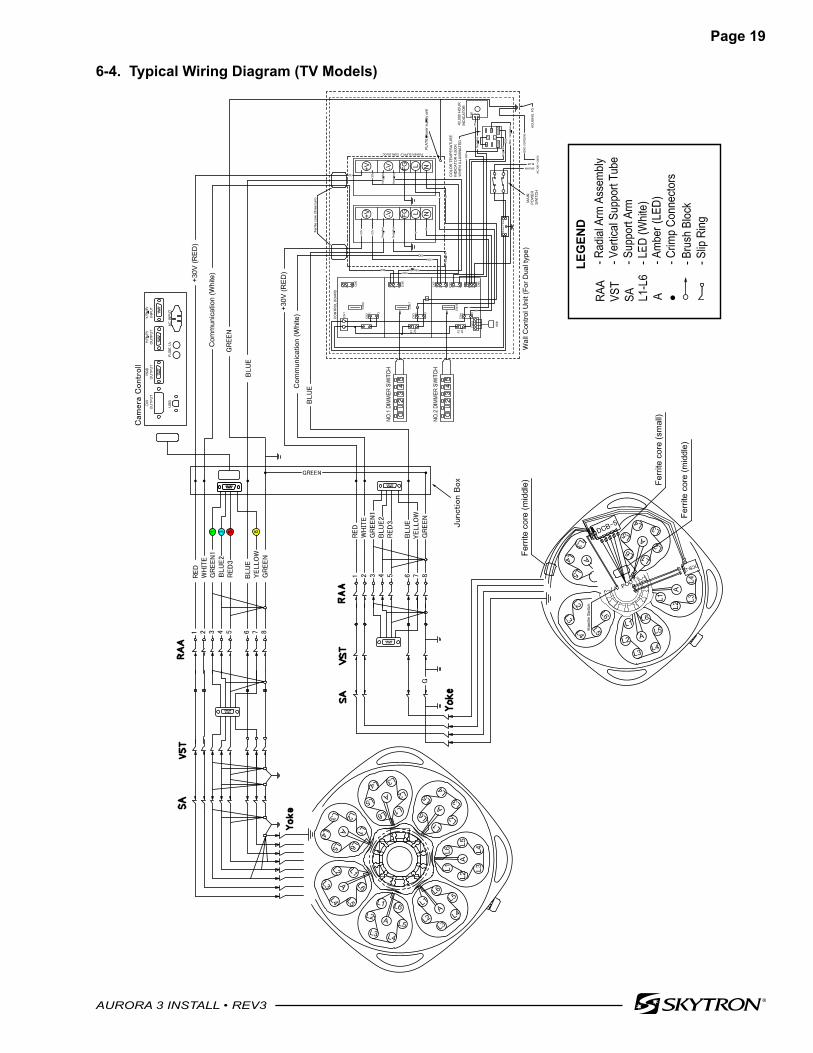
6-4. Typical Wiring Diagram (TV Models)
1 3 5 8
LEG
END
BROWN
BLUE
..................
.........
.........
.........
.....
........
.....
.....
....
Page 20
AURORA 3 INSTALL • REV3
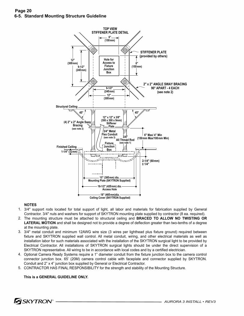
6-5. Standard Mounting Structure Guideline
NOTES 3/4" support rods located for total support of light, all labor and materials for fabrication supplied by General Contractor. 3/4" nuts and washers for support of SKYTRON mounting plate supplied by contractor (8 ea. required). The mounting structure must be attached to structural ceiling and BRACED TO ALLOW NO TWISTING OR LATERAL MOTION and shall be designed not to provide a degree of deflection greater than two-tenths of a degree at the mounting plate. 3/4" metal conduit and minimum 12AWG wire size (3 wires per lighthead plus fixture ground) required between fixture and SKYTRON supplied wall control. All metal conduit, wiring, and other electrical materials as well as installation labor for such materials associated with the installation of the SKYTRON surgical light to be provided by Electrical Contractor. All installations of SKYTRON surgical lights should be under the direct supervision of a SKYTRON representative. All wiring to be in accordance with local codes and by a certified electrician. Optional Camera Ready Systems require a 1” diameter conduit from the fixture junction box to the camera control connector junction box. 65’ (20M) camera control cable with faceplate and connector supplied by SKYTRON. Conduit and 2” x 4” junction box supplied by General or Electrical Contractor.CONTRACTOR HAS FINAL RESPONSIBILITY for the strength and stability of the Mounting Structure. This is a GENERAL GUIDELINE ONLY.
1.
2.
3.
4.
5.
STANDARD MOUNTING STRUCTURE GUIDELINE
45°45°
3/4" MetalFlex Conduit
(see note 3)
FixtureJunction
Box
3/4"All Thread Rod
(see note 1)
12" x 12" x 3/8"(300 x 300 x 9mm)
StiffenerPlate
6" Max/ 4” Min(150mm Max/100mm Min)
1-1/4" (32mm)
2-1/4" (60mm)± 1/4"
Structural Ceiling
Finished Ceiling
STIFFENER PLATE(provided by others)
9-1/2"(240mm)
12"(300mm)
6"(150mm)
STIFFENER PLATE DETAILTOP VIEW
2" x 2" ANGLE SWAY BRACING90° APART - 4 EACH
(see note 2)
15" (380mm) dia.Mounting Plate (SKYTRON Supplied)
18" (460mm)dia.Ceiling Cover (SKYTRON Supplied)
16-1/2" (420mm) dia.Access Hole
Hole forAccess to
FixtureJunction
Box
(4) 2" x 2" Angle Sway Bracing
(see note 2)
6"(150mm)
9-1/2"(240mm)
12"(300mm)
Page 21
AURORA 3 INSTALL • REV3
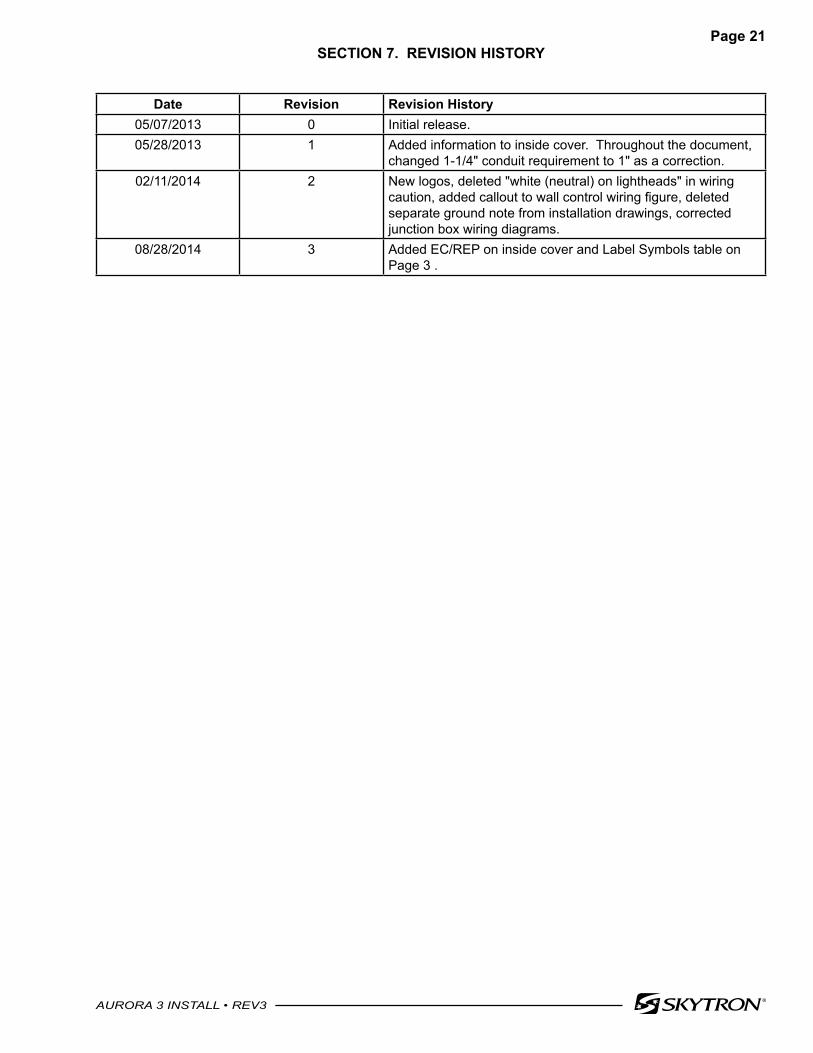
SECTION 7. REVISION HISTORY
Date Revision Revision History05/07/2013 0 Initial release.05/28/2013 1 Added information to inside cover. Throughout the document,
changed 1-1/4" conduit requirement to 1" as a correction.02/11/2014 2 New logos, deleted "white (neutral) on lightheads" in wiring
caution, added callout to wall control wiring figure, deleted separate ground note from installation drawings, corrected junction box wiring diagrams.
08/28/2014 3 Added EC/REP on inside cover and Label Symbols table on Page 3 .

5085 Corporate Exchange Blvd. S.E.Grand Rapids, MI 49512 • 616.656.2900 • FAX 616.656.2906