Embed Size (px)
Citation preview
06/11 506601−01
�������� �����������Page 1
�20 Lennox Industries Inc.Dallas, Texas, USA
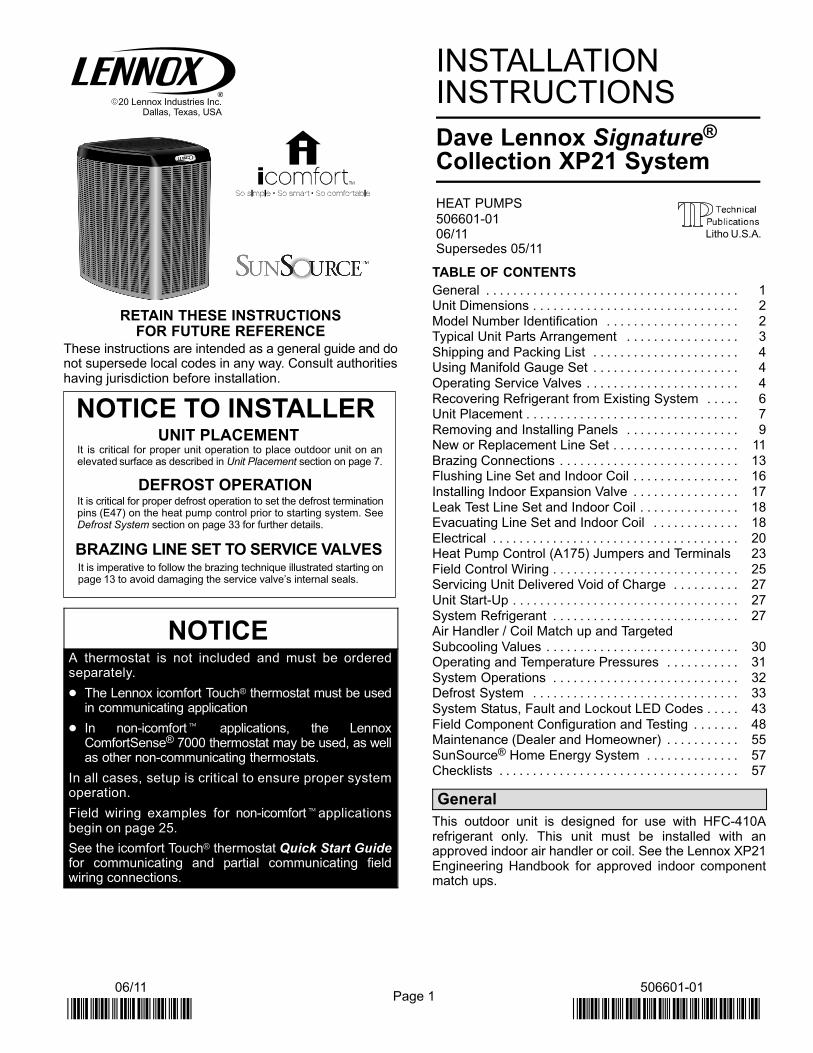
RETAIN THESE INSTRUCTIONSFOR FUTURE REFERENCE
These instructions are intended as a general guide and donot supersede local codes in any way. Consult authoritieshaving jurisdiction before installation.
NOTICE TO INSTALLER
It is critical for proper defrost operation to set the defrost terminationpins (E47) on the heat pump control prior to starting system. SeeDefrost System section on page 33 for further details.
DEFROST OPERATION
UNIT PLACEMENTIt is critical for proper unit operation to place outdoor unit on anelevated surface as described in Unit Placement section on page 7.
BRAZING LINE SET TO SERVICE VALVESIt is imperative to follow the brazing technique illustrated starting onpage 13 to avoid damaging the service valve’s internal seals.
NOTICEA thermostat is not included and must be orderedseparately.
� The Lennox icomfort Touch® thermostat must be usedin communicating application
� In non−icomfort� applications, the LennoxComfortSense® 7000 thermostat may be used, as wellas other non−communicating thermostats.
In all cases, setup is critical to ensure proper systemoperation.
Field wiring examples for non−icomfort�applicationsbegin on page 25.
See the icomfort Touch® thermostat Quick Start Guidefor communicating and partial communicating fieldwiring connections.
INSTALLATIONINSTRUCTIONS
Dave Lennox Signature®
Collection XP21 System
HEAT PUMPS
506601−01 06/11Supersedes 05/11
TABLE OF CONTENTS
General 1. . . . . . . . . . . . . . . . . . . . . . . . . . . . . . . . . . . . . . Unit Dimensions 2. . . . . . . . . . . . . . . . . . . . . . . . . . . . . . .
Model Number Identification 2. . . . . . . . . . . . . . . . . . . . Typical Unit Parts Arrangement 3. . . . . . . . . . . . . . . . .
Shipping and Packing List 4. . . . . . . . . . . . . . . . . . . . . . Using Manifold Gauge Set 4. . . . . . . . . . . . . . . . . . . . . .
Operating Service Valves 4. . . . . . . . . . . . . . . . . . . . . . .
Recovering Refrigerant from Existing System 6. . . . . Unit Placement 7. . . . . . . . . . . . . . . . . . . . . . . . . . . . . . . .
Removing and Installing Panels 9. . . . . . . . . . . . . . . . . New or Replacement Line Set 11. . . . . . . . . . . . . . . . . . .
Brazing Connections 13. . . . . . . . . . . . . . . . . . . . . . . . . . . Flushing Line Set and Indoor Coil 16. . . . . . . . . . . . . . . .
Installing Indoor Expansion Valve 17. . . . . . . . . . . . . . . .
Leak Test Line Set and Indoor Coil 18. . . . . . . . . . . . . . . Evacuating Line Set and Indoor Coil 18. . . . . . . . . . . . .
Electrical 20. . . . . . . . . . . . . . . . . . . . . . . . . . . . . . . . . . . . . Heat Pump Control (A175) Jumpers and Terminals 23
Field Control Wiring 25. . . . . . . . . . . . . . . . . . . . . . . . . . . . Servicing Unit Delivered Void of Charge 27. . . . . . . . . .
Unit Start−Up 27. . . . . . . . . . . . . . . . . . . . . . . . . . . . . . . . . .
System Refrigerant 27. . . . . . . . . . . . . . . . . . . . . . . . . . . . Air Handler / Coil Match up and Targeted
Subcooling Values 30. . . . . . . . . . . . . . . . . . . . . . . . . . . . . Operating and Temperature Pressures 31. . . . . . . . . . .
System Operations 32. . . . . . . . . . . . . . . . . . . . . . . . . . . . Defrost System 33. . . . . . . . . . . . . . . . . . . . . . . . . . . . . . .
System Status, Fault and Lockout LED Codes 43. . . . .
Field Component Configuration and Testing 48. . . . . . . Maintenance (Dealer and Homeowner) 55. . . . . . . . . . .
SunSource® Home Energy System 57. . . . . . . . . . . . . . Checklists 57. . . . . . . . . . . . . . . . . . . . . . . . . . . . . . . . . . . .
General
This outdoor unit is designed for use with HFC−410Arefrigerant only. This unit must be installed with anapproved indoor air handler or coil. See the Lennox XP21Engineering Handbook for approved indoor componentmatch ups.
Litho U.S.A.
Page 2
506601−01
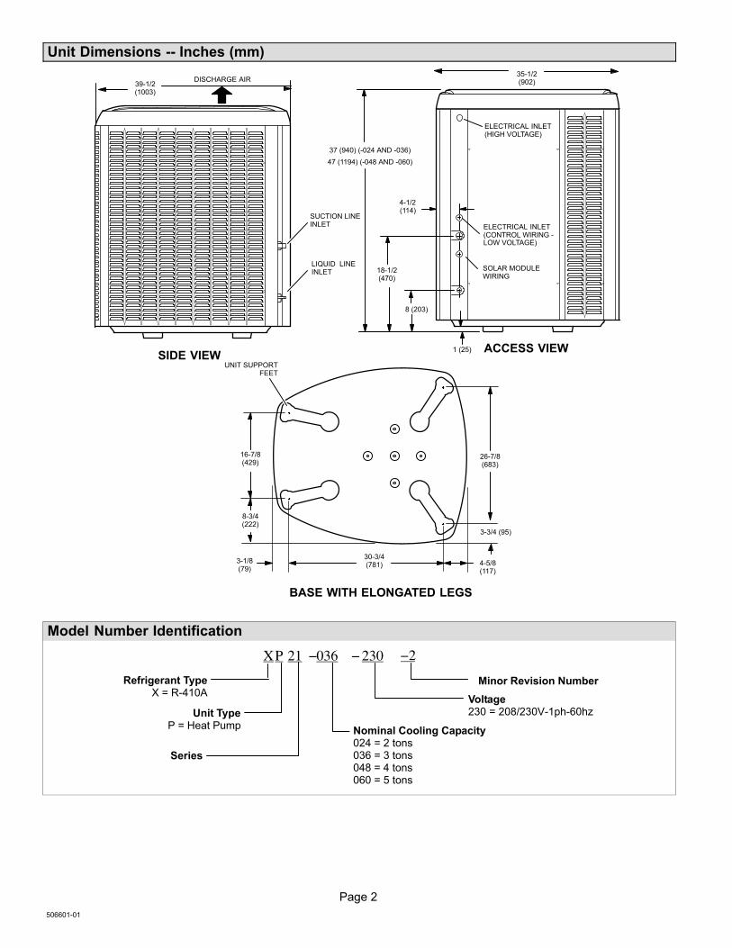
Unit Dimensions −− Inches (mm)
39−1/2(1003)
1 (25)
LIQUID LINEINLET
SIDE VIEWACCESS VIEW
DISCHARGE AIR
4−5/8(117)
BASE WITH ELONGATED LEGS
16−7/8(429)
8−3/4(222)
26−7/8(683)
3−3/4 (95)
30−3/4(781)
3−1/8(79)
SUCTION LINEINLET
UNIT SUPPORTFEET
35−1/2(902)
18−1/2(470)
8 (203)
4−1/2(114)
ELECTRICAL INLET(HIGH VOLTAGE)
37 (940) (−024 AND −036)
SOLAR MODULEWIRING
ELECTRICAL INLET(CONTROL WIRING −LOW VOLTAGE)
47 (1194) (−048 AND −060)
Model Number Identification
P 21 036− −
Unit TypeP = Heat Pump
Series
Nominal Cooling Capacity024 = 2 tons036 = 3 tons048 = 4 tons 060 = 5 tons
Minor Revision Number
230
Voltage230 = 208/230V−1ph−60hz
Refrigerant TypeX = R−410A
X −2
Page 3
XP21 SERIES
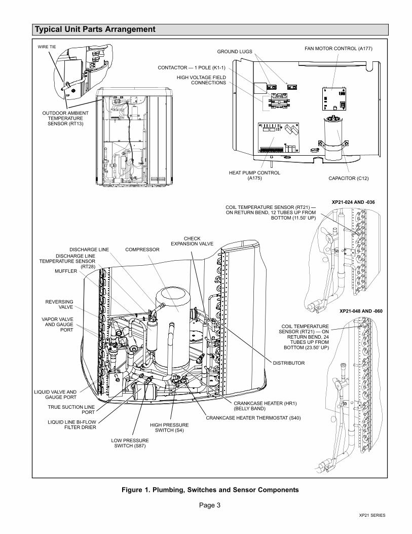
Typical Unit Parts Arrangement
GROUND LUGS
HIGH VOLTAGE FIELDCONNECTIONS
CONTACTOR � 1 POLE (K1−1)
HEAT PUMP CONTROL(A175) CAPACITOR (C12)
FAN MOTOR CONTROL (A177)WIRE TIE
OUTDOOR AMBIENTTEMPERATURESENSOR (RT13)
VAPOR VALVEAND GAUGE
PORT
REVERSINGVALVE
LIQUID LINE BI−FLOWFILTER DRIER
HIGH PRESSURESWITCH (S4)
LIQUID VALVE ANDGAUGE PORT
TRUE SUCTION LINEPORT
LOW PRESSURESWITCH (S87)
CRANKCASE HEATER THERMOSTAT (S40)
CRANKCASE HEATER (HR1)(BELLY BAND)
COMPRESSOR
MUFFLER
DISCHARGE LINE
CHECKEXPANSION VALVE
DISCHARGE LINETEMPERATURE SENSOR
(RT28)
COIL TEMPERATURE SENSOR (RT21) �ON RETURN BEND, 12 TUBES UP FROM
BOTTOM (11.50’ UP)
XP21−024 AND −036
XP21−048 AND −060
COIL TEMPERATURESENSOR (RT21) � ON
RETURN BEND, 24TUBES UP FROM
BOTTOM (23.50’ UP)
DISTRIBUTOR
Figure 1. Plumbing, Switches and Sensor Components
Page 4
506601−01
WARNINGImproper installation, adjustment, alteration, service ormaintenance can cause personal injury, loss of life, ordamage to property.
Installation and service must be performed by a licensedprofessional installer (or equivalent) or a service agency.
CAUTIONPhysical contact with metal edges and corners whileapplying excessive force or rapid motion can result inpersonal injury. Be aware of, and use caution whenworking near these areas during installation or whileservicing this equipment.
IMPORTANTThe Clean Air Act of 1990 bans the intentional venting ofrefrigerant (CFCs, HCFCs AND HFCs) as of July 1,1992. Approved methods of recovery, recycling orreclaiming must be followed. Fines and/or incarcerationmay be levied for noncompliance.
WARNINGElectric Shock Hazard. Can cause injuryor death. Unit must be grounded inaccordance with national and localcodes.
Line voltage is present at all componentswhen unit is not in operation on units withsingle-pole contactors. Disconnect allremote electric power supplies beforeopening access panel. Unit may havemultiple power supplies.
IMPORTANTThis model is designed for use in check expansion valvesystems only. An indoor expansion valve approved foruse with HFC−410A refrigerant must be orderedseparately, and installed prior to operating the system.
Shipping and Packing List
Check unit for shipping damage. Consult last carrierimmediately if damage is found.
1 � Assembled outdoor unit.
1 � Bag assembly which includes the following:
1 � Bushing (for low voltage wiring)
2 � Isolation grommets for liquid and suction lines
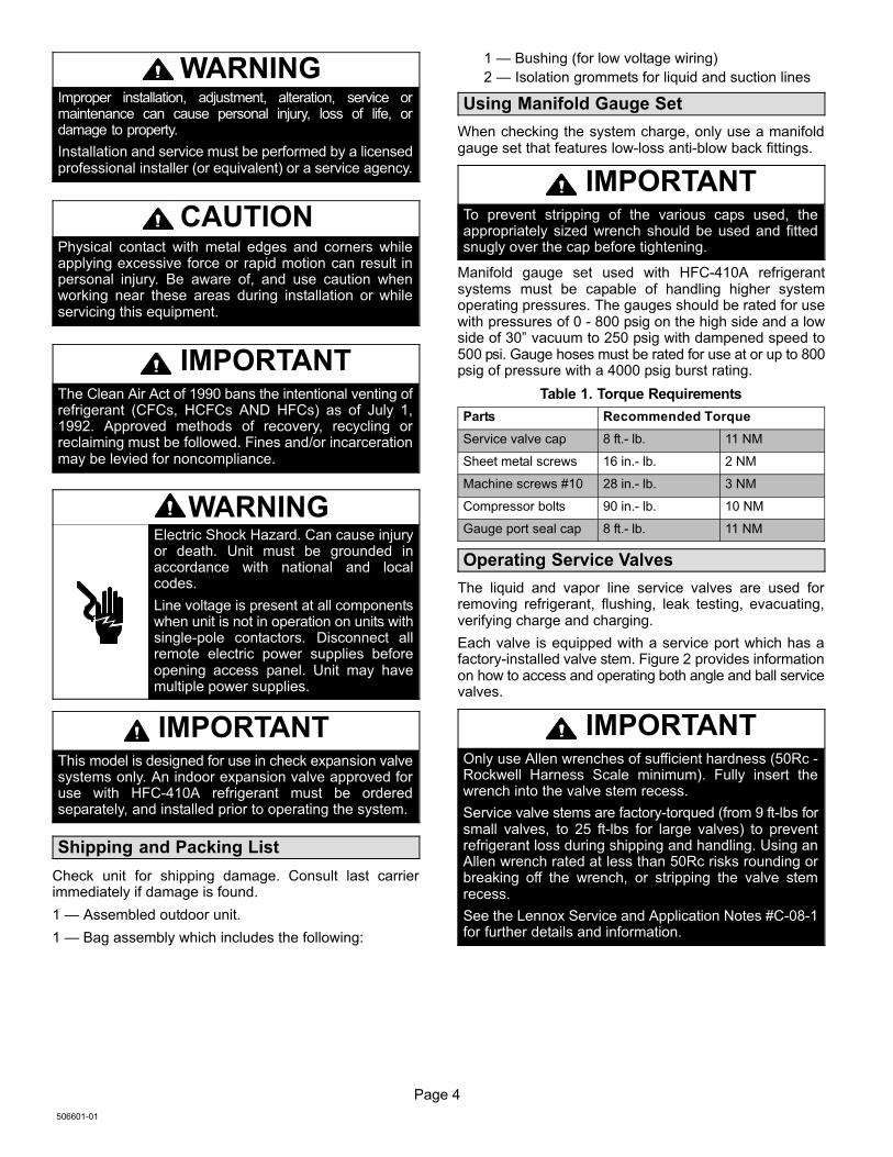
Using Manifold Gauge Set
When checking the system charge, only use a manifoldgauge set that features low−loss anti−blow back fittings.
IMPORTANTTo prevent stripping of the various caps used, theappropriately sized wrench should be used and fittedsnugly over the cap before tightening.
Manifold gauge set used with HFC−410A refrigerantsystems must be capable of handling higher systemoperating pressures. The gauges should be rated for usewith pressures of 0 − 800 psig on the high side and a lowside of 30" vacuum to 250 psig with dampened speed to500 psi. Gauge hoses must be rated for use at or up to 800psig of pressure with a 4000 psig burst rating.
Table 1. Torque Requirements
Parts Recommended Torque
Service valve cap 8 ft.− lb. 11 NM
Sheet metal screws 16 in.− lb. 2 NM
Machine screws #10 28 in.− lb. 3 NM
Compressor bolts 90 in.− lb. 10 NM
Gauge port seal cap 8 ft.− lb. 11 NM
Operating Service Valves
The liquid and vapor line service valves are used forremoving refrigerant, flushing, leak testing, evacuating,verifying charge and charging.
Each valve is equipped with a service port which has afactory−installed valve stem. Figure 2 provides informationon how to access and operating both angle and ball servicevalves.
IMPORTANTOnly use Allen wrenches of sufficient hardness (50Rc −Rockwell Harness Scale minimum). Fully insert thewrench into the valve stem recess.
Service valve stems are factory−torqued (from 9 ft−lbs forsmall valves, to 25 ft−lbs for large valves) to preventrefrigerant loss during shipping and handling. Using anAllen wrench rated at less than 50Rc risks rounding orbreaking off the wrench, or stripping the valve stemrecess.
See the Lennox Service and Application Notes #C−08−1for further details and information.
Page 5
XP21 SERIES
(VALVE STEM SHOWNCLOSED) INSERT HEXWRENCH HERE
SERVICE PORT CORE
SERVICE PORT CAP
ANGLE−TYPE SERVICE VALVE(FRONT−SEATED CLOSED)
TO OUTDOOR UNIT
STEM CAP
(VALVE STEM SHOWN OPEN)INSERT HEX WRENCH HERE
TO INDOORUNIT
ANGLE−TYPE SERVICE VALVE(BACK−SEATED OPENED)
BALL (SHOWNCLOSED)
SERVICE PORTCORE
TO INDOOR UNIT
TO OUTDOORUNIT
TO OPEN ROTATE STEMCOUNTERCLOCKWISE 90°.
TO CLOSE ROTATE STEMCLOCKWISE 90°.
SERVICE PORT
SERVICE PORTCAP
STEM CAP
VALVESTEM
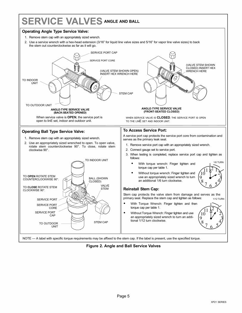
SERVICE VALVES ANGLE AND BALL
Operating Angle Type Service Valve:
1. Remove stem cap with an appropriately sized wrench.
2. Use a service wrench with a hex−head extension (3/16" for liquid line valve sizes and 5/16" for vapor line valve sizes) to backthe stem out counterclockwise as far as it will go.
Operating Ball Type Service Valve:
1. Remove stem cap with an appropriately sized wrench.
2. Use an appropriately sized wrenched to open. To open valve,rotate stem counterclockwise 90°. To close, rotate stemclockwise 90°.
123
4567
8910
11 12
1/12 TURN
To Access Service Port:
A service port cap protects the service port core from contamination andserves as the primary leak seal.
1. Remove service port cap with an appropriately sized wrench.
2. Connect gauge set to service port.
3. When testing is completed, replace service port cap and tighten asfollows:
� With torque wrench: Finger tighten and
torque cap per table 1.
� Without torque wrench: Finger tighten and
use an appropriately sized wrench to turnan additional 1/6 turn clockwise.
123
4567
89101112
1/6 TURN
WHEN SERVICE VALVE IS CLOSED, THE SERVICE PORT IS OPEN
TO THE LINE SET AND INDOOR UNIT.
When service valve is OPEN, the service port isopen to linE set, indoor and outdoor unit.
Reinstall Stem Cap:
Stem cap protects the valve stem from damage and serves as theprimary seal. Replace the stem cap and tighten as follows:
� With Torque Wrench: Finger tighten and then
torque cap per table 1.
� Without Torque Wrench: Finger tighten and use
an appropriately sized wrench to turn an addi-tional 1/12 turn clockwise.
NOTE � A label with specific torque requirements may be affixed to the stem cap. If the label is present, use the specified torque.
Figure 2. Angle and Ball Service Valves
Page 6
506601−01
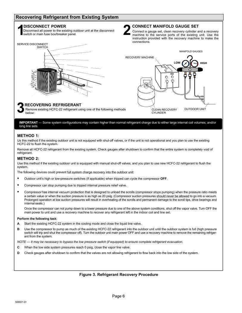
Recovering Refrigerant from Existing System
SERVICE DISCONNECTSWITCH
Disconnect all power to the existing outdoor unit at the disconnectswitch or main fuse box/breaker panel.
DISCONNECT POWER CONNECT MANIFOLD GAUGE SET
MANIFOLD GAUGES
RECOVERY MACHINE
CLEAN RECOVERYCYLINDER
OUTDOOR UNIT
HIGHLOW
Connect a gauge set, clean recovery cylinder and a recoverymachine to the service ports of the existing unit. Use theinstruction provided with the recovery machine to make theconnections.
METHOD 1:Us this method if the existing outdoor unit is not equipped with shut−off valves, or if the unit is not operational and you plan to use the existingHCFC−22 to flush the system.
Remove all HCFC−22 refrigerant from the existing system. Check gauges after shutdown to confirm that the entire system is completely void ofrefrigerant.
METHOD 2:Use this method if the existing outdoor unit is equipped with manual shut−off valves, and you plan to use new HCFC−22 refrigerant to flush thesystem.
The following devices could prevent full system charge recovery into the outdoor unit:
� Outdoor unit’s high or low−pressure switches (if applicable) when tripped can cycle the compressor OFF.
� Compressor can stop pumping due to tripped internal pressure relief valve.
� Compressor has internal vacuum protection that is designed to unload the scrolls (compressor stops pumping) when the pressure ratio meets
a certain value or when the suction pressure is as high as 20 psig. (Compressor suction pressures should never be allowed to go into a vacuum.Prolonged operation at low suction pressures will result in overheating of the scrolls and permanent damage to the scroll tips, drive bearings andinternal seals.)
Once the compressor can not pump down to a lower pressure due to one of the above system conditions, shut off the vapor valve. Turn OFF the
main power to unit and use a recovery machine to recover any refrigerant left in the indoor coil and line set.
Perform the following task:
A Start the existing HCFC−22 system in the cooling mode and close the liquid line valve.
B Use the compressor to pump as much of the existing HCFC−22 refrigerant into the outdoor unit until the outdoor system is full (high pressureswitch will trip and shut the compressor off). Turn the outdoor unit main power OFF and use a recovery machine to remove the remaining refriger-ant from the system.
NOTE � It may be necessary to bypass the low pressure switch (if equipped) to ensure complete refrigerant evacuation.
C When the low side system pressures reach 0 psig, close the vapor line valve.
D Check gauges after shutdown to confirm that the valves are not allowing refrigerant to flow back into the low side of the system.
Remove existing HCFC−22 refrigerant using one of the following methodsbelow:
RECOVERING REFRIGERANT
IMPORTANT � Some system configurations may contain higher than normal refrigerant charge due to either large internal coil volumes, and/orlong line sets.
1 2
3
Figure 3. Refrigerant Recovery Procedure
Page 7
XP21 SERIES
CONTROL PANELACCESS
LOCATION
6 (152)
36 (914)
12 (305)30 (762)
LINE SETCONNECTIONS
24 (610)
LINE SETCONNECTIONS
ACCESS PANEL
REAR VIEW OF UNIT
48 (1219)
MINIMUM CLEARANCE BETWEENTWO UNITS
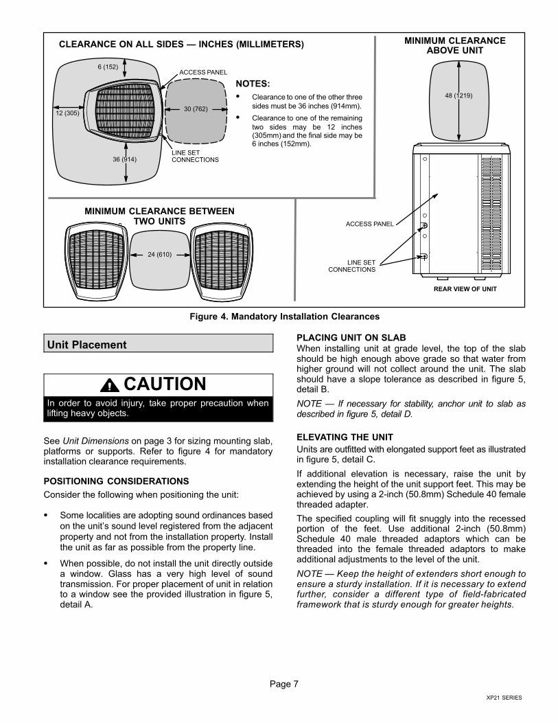
CLEARANCE ON ALL SIDES � INCHES (MILLIMETERS)
ACCESS PANEL
MINIMUM CLEARANCEABOVE UNIT
NOTES:
� Clearance to one of the other three
sides must be 36 inches (914mm).
� Clearance to one of the remaining
two sides may be 12 inches(305mm) and the final side may be6 inches (152mm).
Figure 4. Mandatory Installation Clearances
Unit Placement
CAUTIONIn order to avoid injury, take proper precaution whenlifting heavy objects.
See Unit Dimensions on page 3 for sizing mounting slab,platforms or supports. Refer to figure 4 for mandatoryinstallation clearance requirements.
POSITIONING CONSIDERATIONS
Consider the following when positioning the unit:
� Some localities are adopting sound ordinances based
on the unit’s sound level registered from the adjacent
property and not from the installation property. Installthe unit as far as possible from the property line.
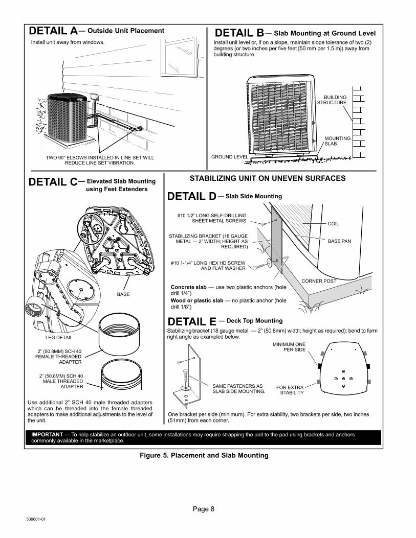
� When possible, do not install the unit directly outsidea window. Glass has a very high level of soundtransmission. For proper placement of unit in relationto a window see the provided illustration in figure 5,detail A.
PLACING UNIT ON SLAB
When installing unit at grade level, the top of the slabshould be high enough above grade so that water fromhigher ground will not collect around the unit. The slabshould have a slope tolerance as described in figure 5,detail B.
NOTE � If necessary for stability, anchor unit to slab asdescribed in figure 5, detail D.
ELEVATING THE UNIT
Units are outfitted with elongated support feet as illustratedin figure 5, detail C.
If additional elevation is necessary, raise the unit byextending the height of the unit support feet. This may beachieved by using a 2−inch (50.8mm) Schedule 40 femalethreaded adapter.
The specified coupling will fit snuggly into the recessedportion of the feet. Use additional 2−inch (50.8mm)Schedule 40 male threaded adaptors which can bethreaded into the female threaded adaptors to makeadditional adjustments to the level of the unit.
NOTE � Keep the height of extenders short enough toensure a sturdy installation. If it is necessary to extendfurther, consider a different type of field−fabricatedframework that is sturdy enough for greater heights.
Page 8
506601−01
LEG DETAIL
BASE
2" (50.8MM) SCH 40FEMALE THREADED
ADAPTER
Concrete slab � use two plastic anchors (holedrill 1/4")
Wood or plastic slab � no plastic anchor (holedrill 1/8")
COIL
BASE PAN
CORNER POST
STABILIZING BRACKET (18 GAUGEMETAL � 2" WIDTH; HEIGHT AS
REQUIRED)
� Slab Side Mounting
#10 1/2" LONG SELF−DRILLINGSHEET METAL SCREWS
#10 1−1/4" LONG HEX HD SCREWAND FLAT WASHER
MINIMUM ONEPER SIDE
Stabilizing bracket (18 gauge metal � 2" (50.8mm) width; height as required); bend to formright angle as exampled below.
FOR EXTRASTABILITY
� Deck Top Mounting
� Elevated Slab Mounting
using Feet Extenders
STABILIZING UNIT ON UNEVEN SURFACES
Install unit level or, if on a slope, maintain slope tolerance of two (2)degrees (or two inches per five feet [50 mm per 1.5 m]) away frombuilding structure.
MOUNTINGSLAB
BUILDINGSTRUCTURE
GROUND LEVEL
� Outside Unit Placement � Slab Mounting at Ground Level
SAME FASTENERS ASSLAB SIDE MOUNTING.
IMPORTANT � To help stabilize an outdoor unit, some installations may require strapping the unit to the pad using brackets and anchorscommonly available in the marketplace.
DETAIL A DETAIL B
DETAIL C
DETAIL D
2" (50.8MM) SCH 40MALE THREADED
ADAPTER
Use additional 2" SCH 40 male threaded adapterswhich can be threaded into the female threadedadapters to make additional adjustments to the level ofthe unit.
TWO 90° ELBOWS INSTALLED IN LINE SET WILLREDUCE LINE SET VIBRATION.
Install unit away from windows.
One bracket per side (minimum). For extra stability, two brackets per side, two inches(51mm) from each corner.
DETAIL E
Figure 5. Placement and Slab Mounting
Page 9
XP21 SERIES
STABILIZING UNIT ON UNEVEN SURFACES
IMPORTANTUnit Stabilizer Bracket Use (field−provided):
Always use stabilizers when unit is raised above thefactory height. (Elevated units could become unstable ingusty wind conditions).
Stabilizers may be used on factory height units whenmounted on unstable an uneven surface.
1. Remove two side louvered panels to expose the unitbase.
2. Install the brackets as illustrated in figure 5, details Dor E using conventional practices.
3. Replace the panels after installation is complete.
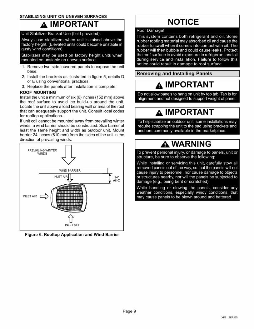
ROOF MOUNTINGInstall the unit a minimum of six (6) inches (152 mm) abovethe roof surface to avoid ice build−up around the unit.Locate the unit above a load bearing wall or area of the roofthat can adequately support the unit. Consult local codesfor rooftop applications.
If unit coil cannot be mounted away from prevailing winterwinds, a wind barrier should be constructed. Size barrier atleast the same height and width as outdoor unit. Mountbarrier 24 inches (610 mm) from the sides of the unit in thedirection of prevailing winds.
24"(610)
WIND BARRIER
PREVAILING WINTERWINDS
INLET AIR
INLET AIR
INLET AIR
Figure 6. Rooftop Application and Wind Barrier
NOTICERoof Damage!
This system contains both refrigerant and oil. Somerubber roofing material may absorbed oil and cause therubber to swell when it comes into contact with oil. Therubber will then bubble and could cause leaks. Protectthe roof surface to avoid exposure to refrigerant and oilduring service and installation. Failure to follow thisnotice could result in damage to roof surface.
Removing and Installing Panels
IMPORTANTDo not allow panels to hang on unit by top tab. Tab is foralignment and not designed to support weight of panel.
IMPORTANTTo help stabilize an outdoor unit, some installations mayrequire strapping the unit to the pad using brackets andanchors commonly available in the marketplace.
WARNINGTo prevent personal injury, or damage to panels, unit orstructure, be sure to observe the following:
While installing or servicing this unit, carefully stow allremoved panels out of the way, so that the panels will notcause injury to personnel, nor cause damage to objectsor structures nearby, nor will the panels be subjected todamage (e.g., being bent or scratched).
While handling or stowing the panels, consider anyweather conditions, especially windy conditions, thatmay cause panels to be blown around and battered.
Page 10
506601−01
REMOVE 4 SCREWS TOREMOVE PANEL FORACCESSING COMPRESSORAND CONTROLS.
Position panel with holes aligned;install screws and tighten.
Detail A
Detail B
ROTATE IN THIS DIRECTION; THENDOWN TO REMOVE PANEL
SCREWHOLES
LIP
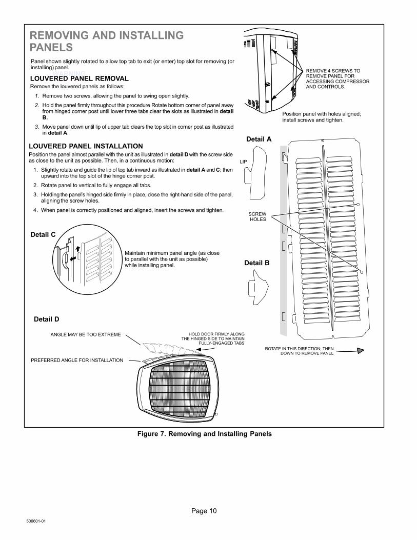
Panel shown slightly rotated to allow top tab to exit (or enter) top slot for removing (orinstalling) panel.
Maintain minimum panel angle (as closeto parallel with the unit as possible)while installing panel.
PREFERRED ANGLE FOR INSTALLATION
Detail D
ANGLE MAY BE TOO EXTREME HOLD DOOR FIRMLY ALONGTHE HINGED SIDE TO MAINTAIN
FULLY−ENGAGED TABS
LOUVERED PANEL REMOVALRemove the louvered panels as follows:
1. Remove two screws, allowing the panel to swing open slightly.
2. Hold the panel firmly throughout this procedure Rotate bottom corner of panel awayfrom hinged corner post until lower three tabs clear the slots as illustrated in detailB.
3. Move panel down until lip of upper tab clears the top slot in corner post as illustratedin detail A.
LOUVERED PANEL INSTALLATIONPosition the panel almost parallel with the unit as illustrated in detail D with the screw sideas close to the unit as possible. Then, in a continuous motion:
1. Slightly rotate and guide the lip of top tab inward as illustrated in detail A and C; thenupward into the top slot of the hinge corner post.
2. Rotate panel to vertical to fully engage all tabs.
3. Holding the panel’s hinged side firmly in place, close the right−hand side of the panel,aligning the screw holes.
4. When panel is correctly positioned and aligned, insert the screws and tighten.
REMOVING AND INSTALLINGPANELS
WARNING
Detail C
Figure 7. Removing and Installing Panels
Page 11
XP21 SERIES
New or Replacement Line Set
REFRIGERANT LINE SET
This section provides information on installation orreplacement of existing line set. If new or replacement lineset is not being installed then proceed to BrazingConnections on page 13.
IMPORTANTLennox highly recommends changing line set whenconverting the existing system from HCFC−22 toHFC−410A. If that is not possible and the line set is theproper size as reference in table 2, use the procedureoutlined under Flushing the System on page 16.
If refrigerant lines are routed through a wall, then seal andisolate the opening so vibration is not transmitted to thebuilding. Pay close attention to line set isolation duringinstallation of any HVAC system. When properly isolatedfrom building structures (walls, ceilings. floors), therefrigerant lines will not create unnecessary vibration andsubsequent sounds. See figure 8 for recommendedinstallation practices. Also, consider the following whenplacing and installing a high−efficiency outdoor unit.
IMPORTANTRefrigerant lines must not contact structure.
Liquid lines that meter the refrigerant, such as RFC1 liquidlines, must not be used in this application. Existing line setof proper size as listed in table 2 may be reused. If systemwas previously charged with HCFC−22 refrigerant, thenexisting line set must be flushed (see Flushing the Systemon page 16).
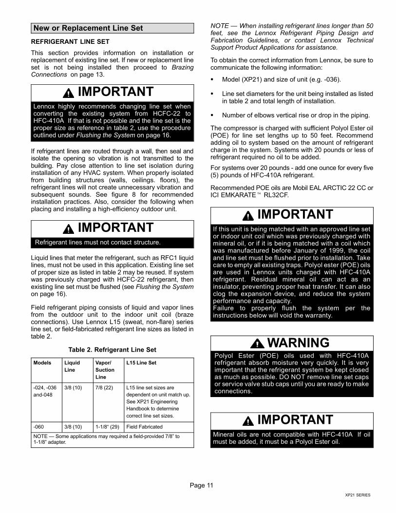
Field refrigerant piping consists of liquid and vapor linesfrom the outdoor unit to the indoor unit coil (brazeconnections). Use Lennox L15 (sweat, non−flare) seriesline set, or field−fabricated refrigerant line sizes as listed intable 2.
Table 2. Refrigerant Line Set
Models Liquid
Line
Vapor/
Suction
Line
L15 Line Set
−024, −036
and−048
3/8 (10) 7/8 (22) L15 line set sizes are
dependent on unit match up.
See XP21 Engineering
Handbook to determine
correct line set sizes.
−060 3/8 (10) 1−1/8� (29) Field Fabricated
NOTE � Some applications may required a field−provided 7/8" to1−1/8" adapter.
NOTE � When installing refrigerant lines longer than 50feet, see the Lennox Refrigerant Piping Design andFabrication Guidelines, or contact Lennox TechnicalSupport Product Applications for assistance.
To obtain the correct information from Lennox, be sure tocommunicate the following information:
� Model (XP21) and size of unit (e.g. −036).
� Line set diameters for the unit being installed as listedin table 2 and total length of installation.
� Number of elbows vertical rise or drop in the piping.
The compressor is charged with sufficient Polyol Ester oil(POE) for line set lengths up to 50 feet. Recommendadding oil to system based on the amount of refrigerantcharge in the system. Systems with 20 pounds or less ofrefrigerant required no oil to be added.
For systems over 20 pounds − add one ounce for every five(5) pounds of HFC−410A refrigerant.
Recommended POE oils are Mobil EAL ARCTIC 22 CC orICI EMKARATE� RL32CF.
IMPORTANTIf this unit is being matched with an approved line setor indoor unit coil which was previously charged withmineral oil, or if it is being matched with a coil whichwas manufactured before January of 1999, the coiland line set must be flushed prior to installation. Takecare to empty all existing traps. Polyol ester (POE) oilsare used in Lennox units charged with HFC−410Arefrigerant. Residual mineral oil can act as aninsulator, preventing proper heat transfer. It can alsoclog the expansion device, and reduce the systemperformance and capacity.Failure to properly flush the system per theinstructions below will void the warranty.
WARNINGPolyol Ester (POE) oils used with HFC−410Arefrigerant absorb moisture very quickly. It is veryimportant that the refrigerant system be kept closedas much as possible. DO NOT remove line set capsor service valve stub caps until you are ready to makeconnections.
IMPORTANTMineral oils are not compatible with HFC−410A. If oilmust be added, it must be a Polyol Ester oil.
Page 12
506601−01
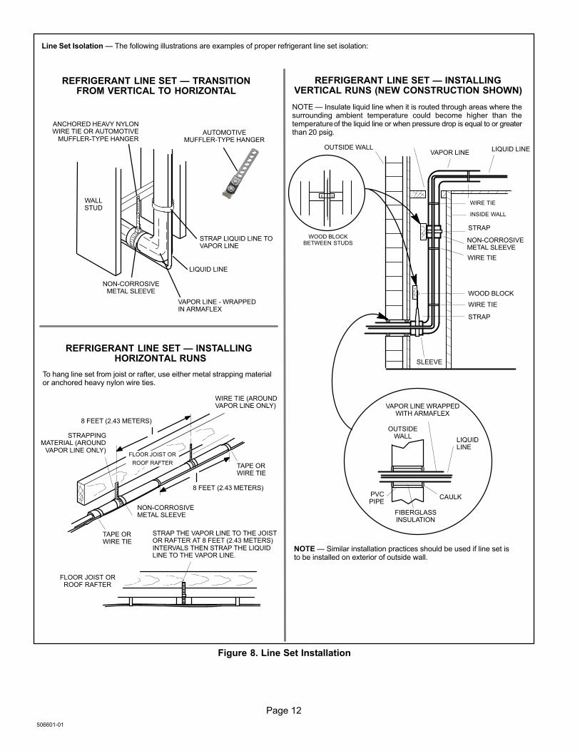
ANCHORED HEAVY NYLONWIRE TIE OR AUTOMOTIVE
MUFFLER-TYPE HANGER
STRAP LIQUID LINE TOVAPOR LINE
WALLSTUD
LIQUID LINE
NON−CORROSIVEMETAL SLEEVE
VAPOR LINE − WRAPPEDIN ARMAFLEX
AUTOMOTIVEMUFFLER-TYPE HANGER
REFRIGERANT LINE SET � TRANSITIONFROM VERTICAL TO HORIZONTAL
Line Set Isolation � The following illustrations are examples of proper refrigerant line set isolation:
STRAPPINGMATERIAL (AROUND
VAPOR LINE ONLY)
TAPE ORWIRE TIE
WIRE TIE (AROUNDVAPOR LINE ONLY)
FLOOR JOIST ORROOF RAFTER
TAPE ORWIRE TIE
To hang line set from joist or rafter, use either metal strapping materialor anchored heavy nylon wire ties.
8 FEET (2.43 METERS)
STRAP THE VAPOR LINE TO THE JOISTOR RAFTER AT 8 FEET (2.43 METERS)INTERVALS THEN STRAP THE LIQUIDLINE TO THE VAPOR LINE.
FLOOR JOIST OR
ROOF RAFTER
REFRIGERANT LINE SET � INSTALLING HORIZONTAL RUNS
NOTE � Similar installation practices should be used if line set isto be installed on exterior of outside wall.
PVCPIPE
FIBERGLASSINSULATION
CAULK
OUTSIDEWALL
VAPOR LINE WRAPPEDWITH ARMAFLEX
LIQUIDLINE
OUTSIDE WALL LIQUID LINEVAPOR LINE
WOOD BLOCKBETWEEN STUDS
STRAP
WOOD BLOCK
STRAP
SLEEVE
WIRE TIE
WIRE TIE
WIRE TIE
INSIDE WALL
REFRIGERANT LINE SET � INSTALLINGVERTICAL RUNS (NEW CONSTRUCTION SHOWN)
NOTE � Insulate liquid line when it is routed through areas where thesurrounding ambient temperature could become higher than thetemperature of the liquid line or when pressure drop is equal to or greaterthan 20 psig.
NON−CORROSIVEMETAL SLEEVE
NON−CORROSIVEMETAL SLEEVE
8 FEET (2.43 METERS)
Figure 8. Line Set Installation
Page 13
XP21 SERIES
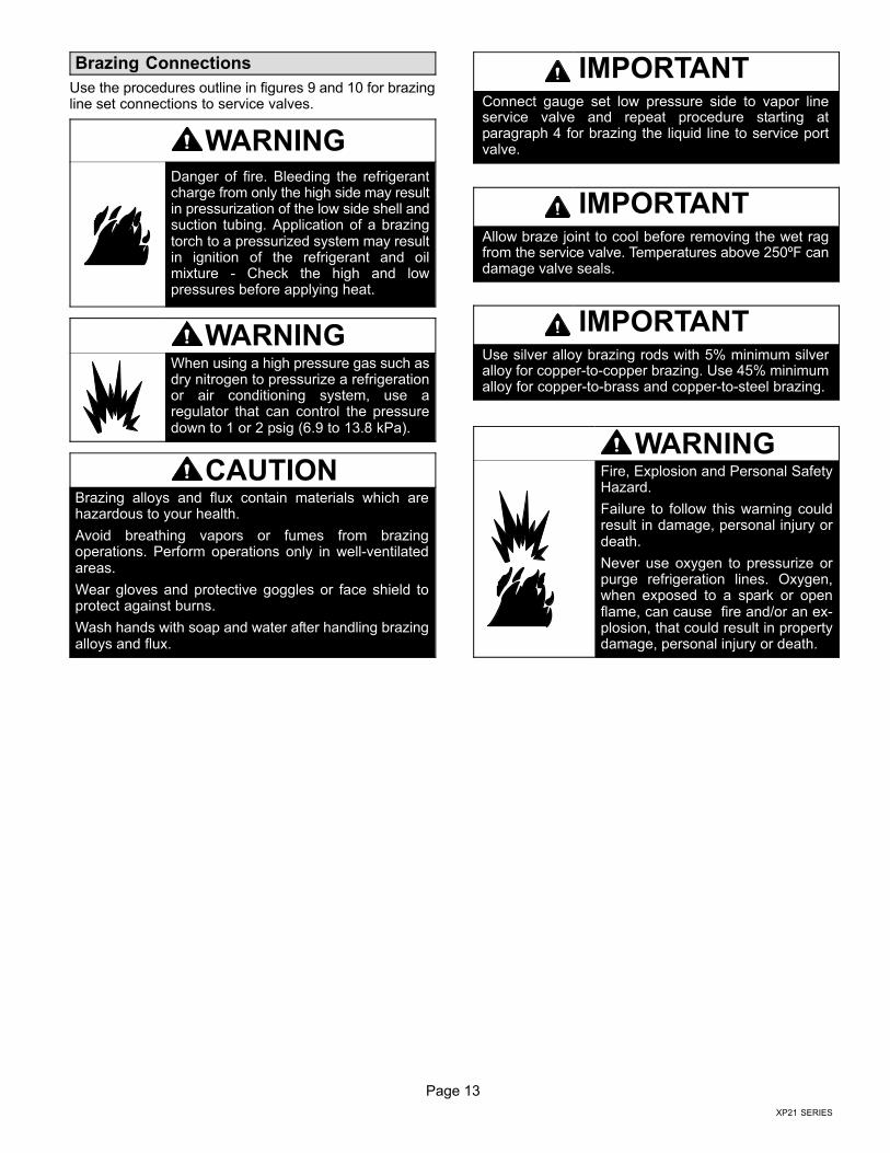
Brazing Connections
Use the procedures outline in figures 9 and 10 for brazingline set connections to service valves.
WARNINGDanger of fire. Bleeding the refrigerantcharge from only the high side may resultin pressurization of the low side shell andsuction tubing. Application of a brazingtorch to a pressurized system may resultin ignition of the refrigerant and oilmixture − Check the high and lowpressures before applying heat.
WARNINGWhen using a high pressure gas such asdry nitrogen to pressurize a refrigerationor air conditioning system, use aregulator that can control the pressuredown to 1 or 2 psig (6.9 to 13.8 kPa).
CAUTIONBrazing alloys and flux contain materials which arehazardous to your health.
Avoid breathing vapors or fumes from brazingoperations. Perform operations only in well−ventilatedareas.
Wear gloves and protective goggles or face shield toprotect against burns.
Wash hands with soap and water after handling brazingalloys and flux.
IMPORTANTConnect gauge set low pressure side to vapor lineservice valve and repeat procedure starting atparagraph 4 for brazing the liquid line to service portvalve.
IMPORTANTAllow braze joint to cool before removing the wet ragfrom the service valve. Temperatures above 250ºF candamage valve seals.
IMPORTANTUse silver alloy brazing rods with 5% minimum silveralloy for copper−to−copper brazing. Use 45% minimumalloy for copper−to−brass and copper−to−steel brazing.
WARNINGFire, Explosion and Personal SafetyHazard.
Failure to follow this warning couldresult in damage, personal injury ordeath.
Never use oxygen to pressurize orpurge refrigeration lines. Oxygen,when exposed to a spark or openflame, can cause fire and/or an ex-plosion, that could result in propertydamage, personal injury or death.

Page 14
506601−01
ATTACH THE MANIFOLD GAUGE SET FOR BRAZINGLIQUID AND SUCTION / VAPOR LINE SERVICE VALVES
OUTDOORUNIT
LIQUID LINE
SUCTION / VAPORLINE
LIQUID LINE SERVICEVALVE
SUCTION /VAPOR LINE
SERVICEVALVE
ATTACHGAUGES
INDOORUNIT
SUCTION / VAPOR SERVICE PORT MUST BEOPEN AND SERVICE PORT CORE REMOVED
TO ALLOW EXIT POINT FOR NITROGEN FLOW
A Connect gauge set low pressure side to liquid lineservice valve (service port).
B Connect gauge set center port to bottle of nitrogen withregulator.
C With valve core removed from the suction / vapor lineservice port, nitrogen flow will have an exit point.
NITROGEN
HIGHLOW
B
A
C
PIPING PANEL REMOVAL AND PREPARING LINESET
CAP AND CORE REMOVAL
Remove piping panel for easier access to service valves. Cut endsof the refrigerant lines square (free from nicks or dents) and deburthe ends. The pipe must remain round. Do not crimp end of the line.
Remove service cap and core from both the suction / vapor andliquid line service ports.1 2
LIQUID LINE SERVICE VALVE
SERVICE PORTCORE
SERVICE PORT CAP
SERVICE PORTCORE
SERVICEPORT CAP
CUT AND DEBUR
LINE SET SIZE MATCHESSERVICE VALVE CONNECTION
COPPER TUBESTUB
SERVICE VALVECONNECTION
REFRIGERANT LINE
DO NOT CRIMP SERVICE VALVECONNECTOR WHEN PIPE IS
SMALLER THAN CONNECTION
REDUCER
3
SUCTION / VAPOR LINESERVICE VALVE
LINE SET SIZE IS SMALLERTHAN CONNECTION
Figure 9. Brazing Procedures
Page 15
XP21 SERIES
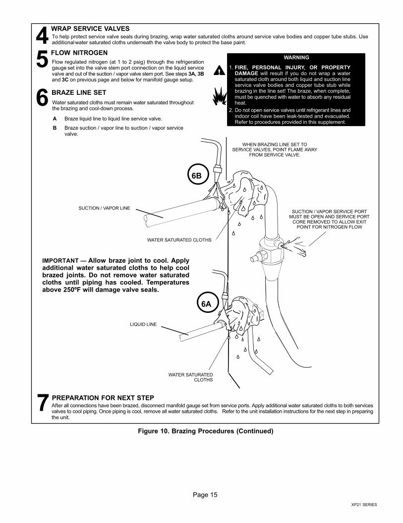
BRAZE LINE SET
Water saturated cloths must remain water saturated throughoutthe brazing and cool−down process.
6
After all connections have been brazed, disconnect manifold gauge set from service ports. Apply additional water saturated cloths to both servicesvalves to cool piping. Once piping is cool, remove all water saturated cloths. Refer to the unit installation instructions for the next step in preparingthe unit.
PREPARATION FOR NEXT STEP7
WRAP SERVICE VALVESTo help protect service valve seals during brazing, wrap water saturated cloths around service valve bodies and copper tube stubs. Useadditional water saturated cloths underneath the valve body to protect the base paint.4FLOW NITROGEN
Flow regulated nitrogen (at 1 to 2 psig) through the refrigerationgauge set into the valve stem port connection on the liquid servicevalve and out of the suction / vapor valve stem port. See steps 3A, 3Band 3C on previous page and below for manifold gauge setup.
5
SUCTION / VAPOR LINE
WHEN BRAZING LINE SET TOSERVICE VALVES, POINT FLAME AWAY
FROM SERVICE VALVE.
WARNING
1. FIRE, PERSONAL INJURY, OR PROPERTYDAMAGE will result if you do not wrap a watersaturated cloth around both liquid and suction lineservice valve bodies and copper tube stub whilebrazing in the line set! The braze, when complete,must be quenched with water to absorb any residualheat.
2. Do not open service valves until refrigerant lines andindoor coil have been leak−tested and evacuated.Refer to procedures provided in this supplement.
LIQUID LINE
WATER SATURATEDCLOTHS
WATER SATURATED CLOTHS
A Braze liquid line to liquid line service valve.
B Braze suction / vapor line to suction / vapor servicevalve.
6A
6B
SUCTION / VAPOR SERVICE PORTMUST BE OPEN AND SERVICE PORT
CORE REMOVED TO ALLOW EXITPOINT FOR NITROGEN FLOW
IMPORTANT � Allow braze joint to cool. Applyadditional water saturated cloths to help coolbrazed joints. Do not remove water saturatedcloths until piping has cooled. Temperaturesabove 250ºF will damage valve seals.
Figure 10. Brazing Procedures (Continued)
Page 16
506601−01
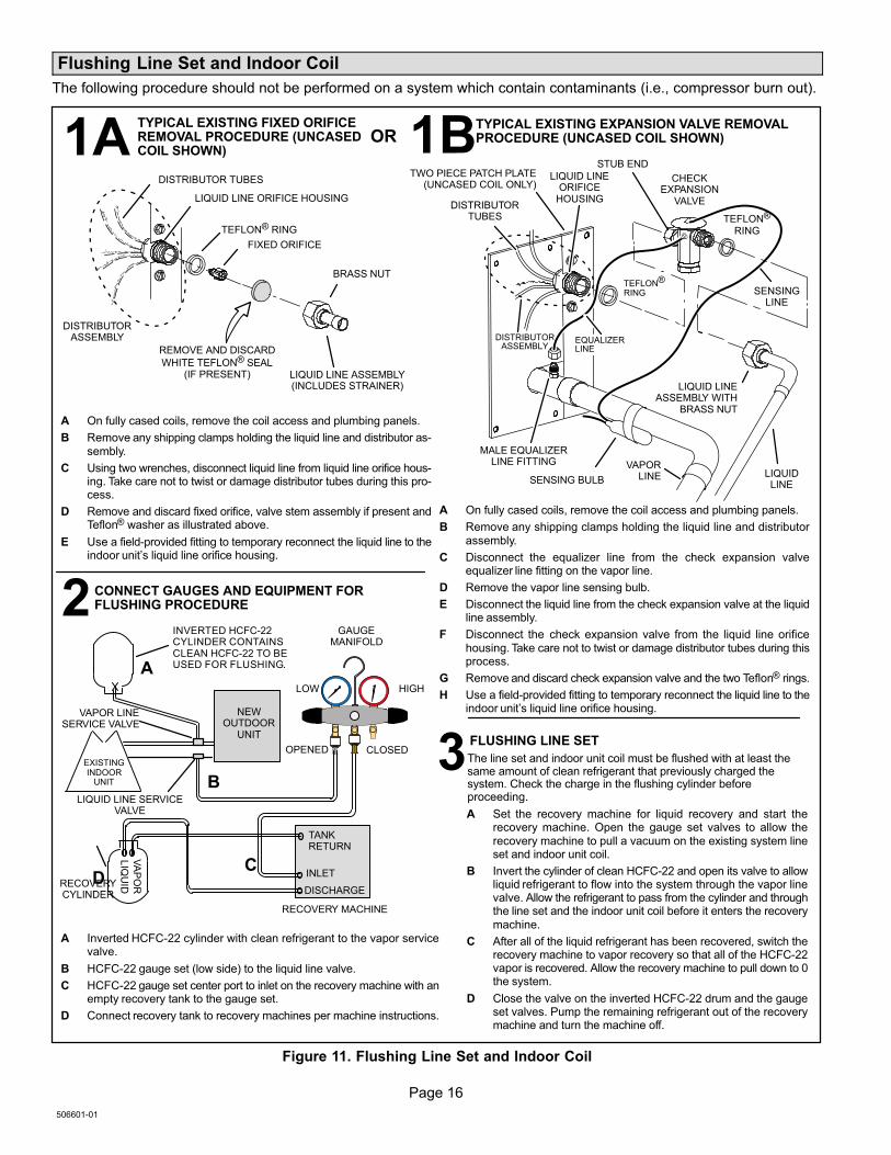
Flushing Line Set and Indoor Coil
The following procedure should not be performed on a system which contain contaminants (i.e., compressor burn out).
SENSINGLINE
TEFLON® RING
FIXED ORIFICE
BRASS NUT
LIQUID LINE ASSEMBLY(INCLUDES STRAINER)
LIQUID LINE ORIFICE HOUSING
DISTRIBUTOR TUBES
DISTRIBUTORASSEMBLY
REMOVE AND DISCARD
WHITE TEFLON® SEAL(IF PRESENT)
A On fully cased coils, remove the coil access and plumbing panels.
B Remove any shipping clamps holding the liquid line and distributor as-sembly.
C Using two wrenches, disconnect liquid line from liquid line orifice hous-ing. Take care not to twist or damage distributor tubes during this pro-cess.
D Remove and discard fixed orifice, valve stem assembly if present andTeflon® washer as illustrated above.
E Use a field−provided fitting to temporary reconnect the liquid line to theindoor unit’s liquid line orifice housing.
TYPICAL EXISTING FIXED ORIFICEREMOVAL PROCEDURE (UNCASEDCOIL SHOWN)
TYPICAL EXISTING EXPANSION VALVE REMOVALPROCEDURE (UNCASED COIL SHOWN)
TWO PIECE PATCH PLATE(UNCASED COIL ONLY)
VAPORLINE
DISTRIBUTORASSEMBLY
DISTRIBUTORTUBES
LIQUIDLINE
MALE EQUALIZERLINE FITTING
EQUALIZERLINE
CHECKEXPANSION
VALVE
TEFLON®
RING
STUB END
TEFLON®
RING
SENSING BULB
LIQUID LINEORIFICE
HOUSING
LIQUID LINEASSEMBLY WITH
BRASS NUT
A On fully cased coils, remove the coil access and plumbing panels.
B Remove any shipping clamps holding the liquid line and distributorassembly.
C Disconnect the equalizer line from the check expansion valveequalizer line fitting on the vapor line.
D Remove the vapor line sensing bulb.
E Disconnect the liquid line from the check expansion valve at the liquidline assembly.
F Disconnect the check expansion valve from the liquid line orificehousing. Take care not to twist or damage distributor tubes during thisprocess.
G Remove and discard check expansion valve and the two Teflon® rings.
H Use a field−provided fitting to temporary reconnect the liquid line to theindoor unit’s liquid line orifice housing.
LOW HIGH
EXISTINGINDOOR
UNIT
GAUGEMANIFOLD
INVERTED HCFC−22CYLINDER CONTAINSCLEAN HCFC−22 TO BEUSED FOR FLUSHING.
LIQUID LINE SERVICEVALVE
INLET
DISCHARGE
TANKRETURN
CLOSEDOPENED
RECOVERYCYLINDER
RECOVERY MACHINE
NEWOUTDOOR
UNIT
VAPOR LINESERVICE VALVE
VA
PO
R
LIQ
UID
1
A Inverted HCFC−22 cylinder with clean refrigerant to the vapor servicevalve.
B HCFC−22 gauge set (low side) to the liquid line valve.
C HCFC−22 gauge set center port to inlet on the recovery machine with anempty recovery tank to the gauge set.
D Connect recovery tank to recovery machines per machine instructions.
CONNECT GAUGES AND EQUIPMENT FORFLUSHING PROCEDURE
A
B
CD
B
OR
FLUSHING LINE SET
A Set the recovery machine for liquid recovery and start therecovery machine. Open the gauge set valves to allow therecovery machine to pull a vacuum on the existing system lineset and indoor unit coil.
B Invert the cylinder of clean HCFC−22 and open its valve to allowliquid refrigerant to flow into the system through the vapor linevalve. Allow the refrigerant to pass from the cylinder and throughthe line set and the indoor unit coil before it enters the recoverymachine.
C After all of the liquid refrigerant has been recovered, switch therecovery machine to vapor recovery so that all of the HCFC−22vapor is recovered. Allow the recovery machine to pull down to 0the system.
D Close the valve on the inverted HCFC−22 drum and the gaugeset valves. Pump the remaining refrigerant out of the recoverymachine and turn the machine off.
The line set and indoor unit coil must be flushed with at least thesame amount of clean refrigerant that previously charged thesystem. Check the charge in the flushing cylinder beforeproceeding.
1A
2
3
1B
Figure 11. Flushing Line Set and Indoor Coil
Page 17
XP21 SERIES
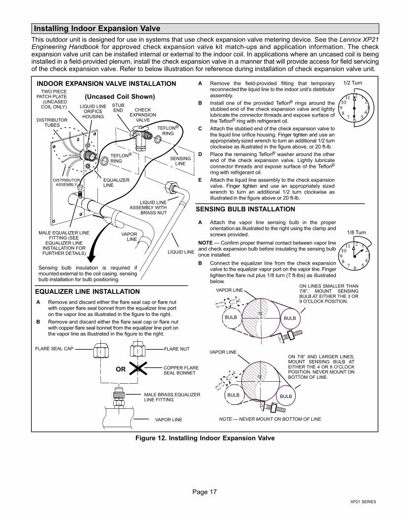
Installing Indoor Expansion Valve
This outdoor unit is designed for use in systems that use check expansion valve metering device. See the Lennox XP21Engineering Handbook for approved check expansion valve kit match−ups and application information. The checkexpansion valve unit can be installed internal or external to the indoor coil. In applications where an uncased coil is beinginstalled in a field−provided plenum, install the check expansion valve in a manner that will provide access for field servicingof the check expansion valve. Refer to below illustration for reference during installation of check expansion valve unit.
A Attach the vapor line sensing bulb in the properorientation as illustrated to the right using the clamp andscrews provided.
NOTE � Confirm proper thermal contact between vapor lineand check expansion bulb before insulating the sensing bulbonce installed.
B Connect the equalizer line from the check expansionvalve to the equalizer vapor port on the vapor line. Fingertighten the flare nut plus 1/8 turn (7 ft−lbs) as illustratedbelow.
TWO PIECEPATCH PLATE
(UNCASEDCOIL ONLY)
VAPORLINE
LIQUID LINEORIFICE
HOUSINGDISTRIBUTOR
TUBES
LIQUID LINE
MALE EQUALIZER LINEFITTING (SEE
EQUALIZER LINEINSTALLATION FORFURTHER DETAILS)
SENSINGLINE
EQUALIZERLINE
CHECKEXPANSION
VALVE
TEFLON®
RING
(Uncased Coil Shown)
Sensing bulb insulation is required ifmounted external to the coil casing. sensingbulb installation for bulb positioning.
STUBEND
TEFLON®
RING
LIQUID LINEASSEMBLY WITH
BRASS NUT
DISTRIBUTORASSEMBLY
A Remove the field−provided fitting that temporaryreconnected the liquid line to the indoor unit’s distributorassembly.
B Install one of the provided Teflon® rings around thestubbed end of the check expansion valve and lightlylubricate the connector threads and expose surface ofthe Teflon® ring with refrigerant oil.
C Attach the stubbed end of the check expansion valve tothe liquid line orifice housing. Finger tighten and use anappropriately sized wrench to turn an additional 1/2 turnclockwise as illustrated in the figure above, or 20 ft−lb.
D Place the remaining Teflon® washer around the otherend of the check expansion valve. Lightly lubricateconnector threads and expose surface of the Teflon®
ring with refrigerant oil.
E Attach the liquid line assembly to the check expansionvalve. Finger tighten and use an appropriately sizedwrench to turn an additional 1/2 turn clockwise asillustrated in the figure above or 20 ft−lb.
ON 7/8" AND LARGER LINES,MOUNT SENSING BULB ATEITHER THE 4 OR 8 O’CLOCKPOSITION. NEVER MOUNT ONBOTTOM OF LINE.
12
ON LINES SMALLER THAN7/8", MOUNT SENSINGBULB AT EITHER THE 3 OR9 O’CLOCK POSITION.
12
BULB
VAPOR LINE
VAPOR LINE
NOTE � NEVER MOUNT ON BOTTOM OF LINE.
BULB
BULBBULB
VAPOR LINE
FLARE NUT
COPPER FLARESEAL BONNET
MALE BRASS EQUALIZERLINE FITTING
FLARE SEAL CAP
OR
123
4567
8910
11 12
1/2 Turn
SENSING BULB INSTALLATION
EQUALIZER LINE INSTALLATION
123
4567
8910
11 12
1/8 Turn
A Remove and discard either the flare seal cap or flare nutwith copper flare seal bonnet from the equalizer line porton the vapor line as illustrated in the figure to the right.
B Remove and discard either the flare seal cap or flare nutwith copper flare seal bonnet from the equalizer line port onthe vapor line as illustrated in the figure to the right.
INDOOR EXPANSION VALVE INSTALLATION
Figure 12. Installing Indoor Expansion Valve
Page 18
506601−01
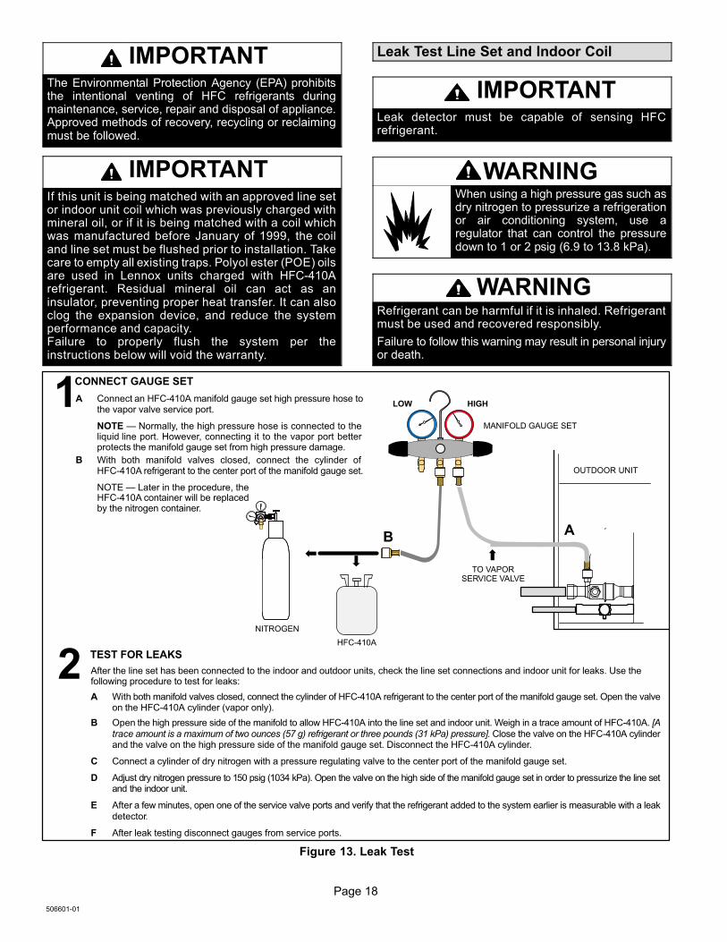
IMPORTANTThe Environmental Protection Agency (EPA) prohibitsthe intentional venting of HFC refrigerants duringmaintenance, service, repair and disposal of appliance.Approved methods of recovery, recycling or reclaimingmust be followed.
IMPORTANTIf this unit is being matched with an approved line setor indoor unit coil which was previously charged withmineral oil, or if it is being matched with a coil whichwas manufactured before January of 1999, the coiland line set must be flushed prior to installation. Takecare to empty all existing traps. Polyol ester (POE) oilsare used in Lennox units charged with HFC−410Arefrigerant. Residual mineral oil can act as aninsulator, preventing proper heat transfer. It can alsoclog the expansion device, and reduce the systemperformance and capacity.Failure to properly flush the system per theinstructions below will void the warranty.
Leak Test Line Set and Indoor Coil
IMPORTANTLeak detector must be capable of sensing HFCrefrigerant.
WARNINGWhen using a high pressure gas such asdry nitrogen to pressurize a refrigerationor air conditioning system, use aregulator that can control the pressuredown to 1 or 2 psig (6.9 to 13.8 kPa).
WARNINGRefrigerant can be harmful if it is inhaled. Refrigerantmust be used and recovered responsibly.
Failure to follow this warning may result in personal injuryor death.
TO VAPORSERVICE VALVE
HFC−410A
MANIFOLD GAUGE SET
OUTDOOR UNIT
HIGHLOW
NITROGEN
A With both manifold valves closed, connect the cylinder of HFC−410A refrigerant to the center port of the manifold gauge set. Open the valveon the HFC−410A cylinder (vapor only).
B Open the high pressure side of the manifold to allow HFC−410A into the line set and indoor unit. Weigh in a trace amount of HFC−410A. [Atrace amount is a maximum of two ounces (57 g) refrigerant or three pounds (31 kPa) pressure]. Close the valve on the HFC−410A cylinderand the valve on the high pressure side of the manifold gauge set. Disconnect the HFC−410A cylinder.
C Connect a cylinder of dry nitrogen with a pressure regulating valve to the center port of the manifold gauge set.
D Adjust dry nitrogen pressure to 150 psig (1034 kPa). Open the valve on the high side of the manifold gauge set in order to pressurize the line setand the indoor unit.
E After a few minutes, open one of the service valve ports and verify that the refrigerant added to the system earlier is measurable with a leakdetector.
F After leak testing disconnect gauges from service ports.
After the line set has been connected to the indoor and outdoor units, check the line set connections and indoor unit for leaks. Use thefollowing procedure to test for leaks:
A Connect an HFC−410A manifold gauge set high pressure hose tothe vapor valve service port.
NOTE � Normally, the high pressure hose is connected to theliquid line port. However, connecting it to the vapor port betterprotects the manifold gauge set from high pressure damage.
B With both manifold valves closed, connect the cylinder ofHFC−410A refrigerant to the center port of the manifold gauge set.
NOTE � Later in the procedure, theHFC−410A container will be replacedby the nitrogen container.
1CONNECT GAUGE SET
2TEST FOR LEAKS
AB
Figure 13. Leak Test
Page 19
XP21 SERIES
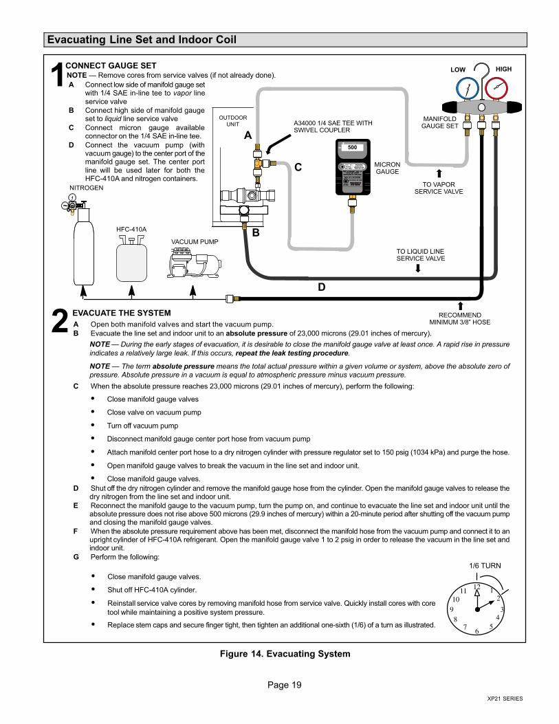
Evacuating Line Set and Indoor Coil
A Open both manifold valves and start the vacuum pump.
B Evacuate the line set and indoor unit to an absolute pressure of 23,000 microns (29.01 inches of mercury).
NOTE � During the early stages of evacuation, it is desirable to close the manifold gauge valve at least once. A rapid rise in pressure
indicates a relatively large leak. If this occurs, repeat the leak testing procedure.
NOTE � The term absolute pressure means the total actual pressure within a given volume or system, above the absolute zero ofpressure. Absolute pressure in a vacuum is equal to atmospheric pressure minus vacuum pressure.
C When the absolute pressure reaches 23,000 microns (29.01 inches of mercury), perform the following:
� Close manifold gauge valves
� Close valve on vacuum pump
� Turn off vacuum pump
� Disconnect manifold gauge center port hose from vacuum pump
� Attach manifold center port hose to a dry nitrogen cylinder with pressure regulator set to 150 psig (1034 kPa) and purge the hose.
� Open manifold gauge valves to break the vacuum in the line set and indoor unit.
� Close manifold gauge valves.
D Shut off the dry nitrogen cylinder and remove the manifold gauge hose from the cylinder. Open the manifold gauge valves to release thedry nitrogen from the line set and indoor unit.
E Reconnect the manifold gauge to the vacuum pump, turn the pump on, and continue to evacuate the line set and indoor unit until theabsolute pressure does not rise above 500 microns (29.9 inches of mercury) within a 20−minute period after shutting off the vacuum pumpand closing the manifold gauge valves.
F When the absolute pressure requirement above has been met, disconnect the manifold hose from the vacuum pump and connect it to anupright cylinder of HFC−410A refrigerant. Open the manifold gauge valve 1 to 2 psig in order to release the vacuum in the line set andindoor unit.
G Perform the following:
OUTDOOR
UNIT
TO VAPORSERVICE VALVE
TO LIQUID LINESERVICE VALVE
MICRONGAUGE
VACUUM PUMP
A34000 1/4 SAE TEE WITHSWIVEL COUPLER
500
MANIFOLDGAUGE SET
HFC−410A
RECOMMENDMINIMUM 3/8" HOSE
A Connect low side of manifold gauge setwith 1/4 SAE in−line tee to vapor lineservice valve
B Connect high side of manifold gaugeset to liquid line service valve
C Connect micron gauge availableconnector on the 1/4 SAE in−line tee.
D Connect the vacuum pump (withvacuum gauge) to the center port of themanifold gauge set. The center portline will be used later for both theHFC−410A and nitrogen containers.
HIGHLOW
12
34
56
78
910
11 12
1/6 TURN
NITROGEN
1CONNECT GAUGE SET
A
B
C
D
2EVACUATE THE SYSTEM
NOTE � Remove cores from service valves (if not already done).
� Close manifold gauge valves.
� Shut off HFC−410A cylinder.
� Reinstall service valve cores by removing manifold hose from service valve. Quickly install cores with core
tool while maintaining a positive system pressure.
� Replace stem caps and secure finger tight, then tighten an additional one−sixth (1/6) of a turn as illustrated.
Figure 14. Evacuating System
Page 20
506601−01
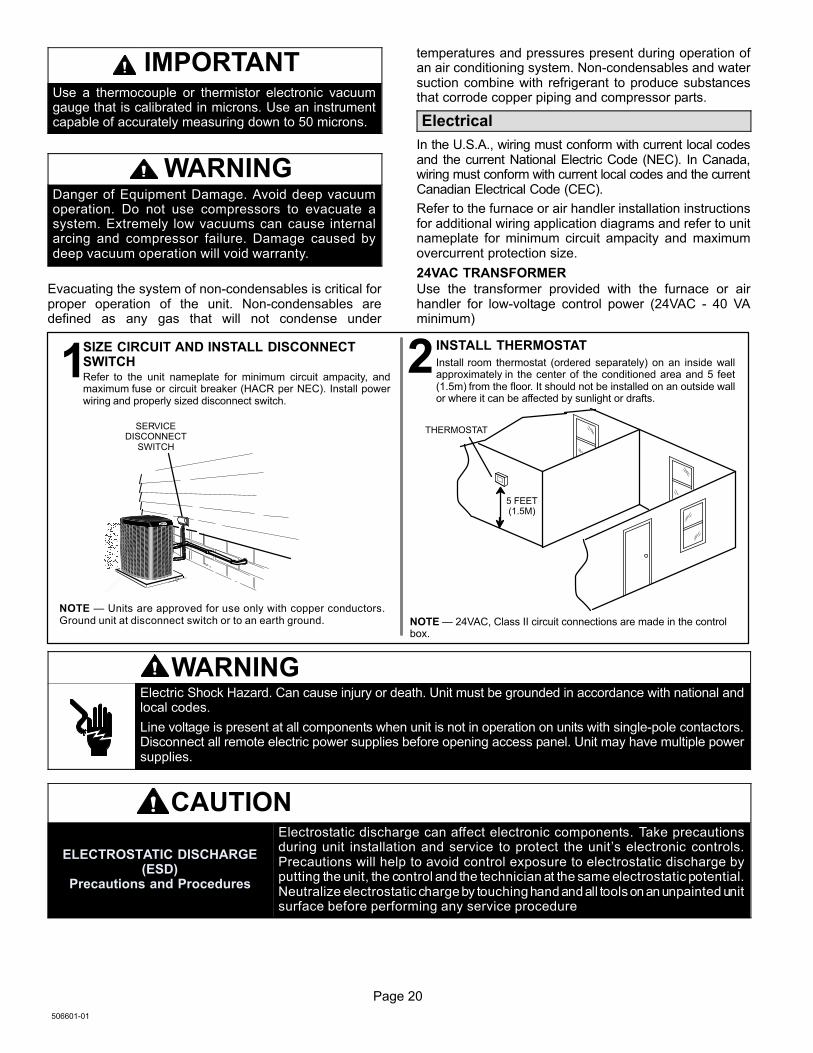
IMPORTANTUse a thermocouple or thermistor electronic vacuumgauge that is calibrated in microns. Use an instrumentcapable of accurately measuring down to 50 microns.
WARNINGDanger of Equipment Damage. Avoid deep vacuumoperation. Do not use compressors to evacuate asystem. Extremely low vacuums can cause internalarcing and compressor failure. Damage caused bydeep vacuum operation will void warranty.
Evacuating the system of non−condensables is critical forproper operation of the unit. Non−condensables aredefined as any gas that will not condense under
temperatures and pressures present during operation ofan air conditioning system. Non−condensables and watersuction combine with refrigerant to produce substancesthat corrode copper piping and compressor parts.
Electrical
In the U.S.A., wiring must conform with current local codesand the current National Electric Code (NEC). In Canada,wiring must conform with current local codes and the currentCanadian Electrical Code (CEC).
Refer to the furnace or air handler installation instructionsfor additional wiring application diagrams and refer to unitnameplate for minimum circuit ampacity and maximumovercurrent protection size.
24VAC TRANSFORMER
Use the transformer provided with the furnace or airhandler for low-voltage control power (24VAC − 40 VAminimum)
Refer to the unit nameplate for minimum circuit ampacity, andmaximum fuse or circuit breaker (HACR per NEC). Install powerwiring and properly sized disconnect switch.
NOTE � Units are approved for use only with copper conductors.Ground unit at disconnect switch or to an earth ground.
SIZE CIRCUIT AND INSTALL DISCONNECTSWITCH1
NOTE � 24VAC, Class II circuit connections are made in the controlbox.
Install room thermostat (ordered separately) on an inside wallapproximately in the center of the conditioned area and 5 feet(1.5m) from the floor. It should not be installed on an outside wallor where it can be affected by sunlight or drafts.
THERMOSTAT
5 FEET(1.5M)
INSTALL THERMOSTAT
2
SERVICEDISCONNECT
SWITCH
WARNINGElectric Shock Hazard. Can cause injury or death. Unit must be grounded in accordance with national andlocal codes.
Line voltage is present at all components when unit is not in operation on units with single-pole contactors.Disconnect all remote electric power supplies before opening access panel. Unit may have multiple powersupplies.
CAUTION
ELECTROSTATIC DISCHARGE(ESD)
Precautions and Procedures
Electrostatic discharge can affect electronic components. Take precautionsduring unit installation and service to protect the unit’s electronic controls.Precautions will help to avoid control exposure to electrostatic discharge byputting the unit, the control and the technician at the same electrostatic potential.Neutralize electrostatic charge by touching hand and all tools on an unpainted unitsurface before performing any service procedure
Page 21
XP21 SERIES
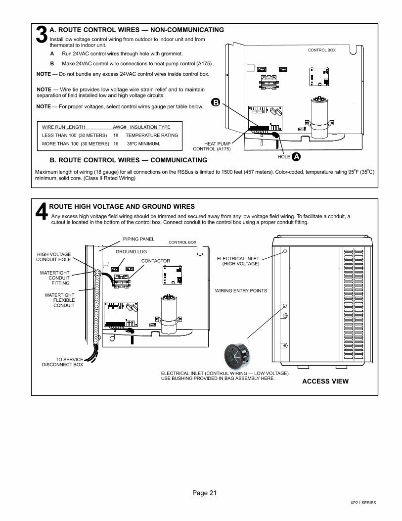
NOTE � For proper voltages, select control wires gauge per table below.
WIRE RUN LENGTH AWG# INSULATION TYPE
LESS THAN 100’ (30 METERS) 18 TEMPERATURE RATING
MORE THAN 100’ (30 METERS) 16 35ºC MINIMUM.
NOTE � Wire tie provides low voltage wire strain relief and to maintainseparation of field installed low and high voltage circuits.
NOTE � Do not bundle any excess 24VAC control wires inside control box.
A. ROUTE CONTROL WIRES � NON−COMMUNICATING
A
B
HEAT PUMPCONTROL (A175)
CONTROL BOX
HOLE
Install low voltage control wiring from outdoor to indoor unit and fromthermostat to indoor unit.
3A Run 24VAC control wires through hole with grommet.
B Make 24VAC control wire connections to heat pump control (A175) .
B. ROUTE CONTROL WIRES � COMMUNICATING
Maximum length of wiring (18 gauge) for all connections on the RSBus is limited to 1500 feet (457 meters). Color−coded, temperature rating 95ºF (35ºC)minimum, solid core. (Class II Rated Wiring)
Any excess high voltage field wiring should be trimmed and secured away from any low voltage field wiring. To facilitate a conduit, acutout is located in the bottom of the control box. Connect conduit to the control box using a proper conduit fitting.
ROUTE HIGH VOLTAGE AND GROUND WIRES
CONTROL BOXPIPING PANEL
HIGH VOLTAGECONDUIT HOLE
GROUND LUG
CONTACTOR
WATERTIGHTCONDUIT
FITTING
WATERTIGHTFLEXIBLECONDUIT
TO SERVICEDISCONNECT BOX
ACCESS VIEW
ELECTRICAL INLET(HIGH VOLTAGE)
WIRING ENTRY POINTS
ELECTRICAL INLET (CONTROL WIRING � LOW VOLTAGE).USE BUSHING PROVIDED IN BAG ASSEMBLY HERE.
4
Page 22
506601−01
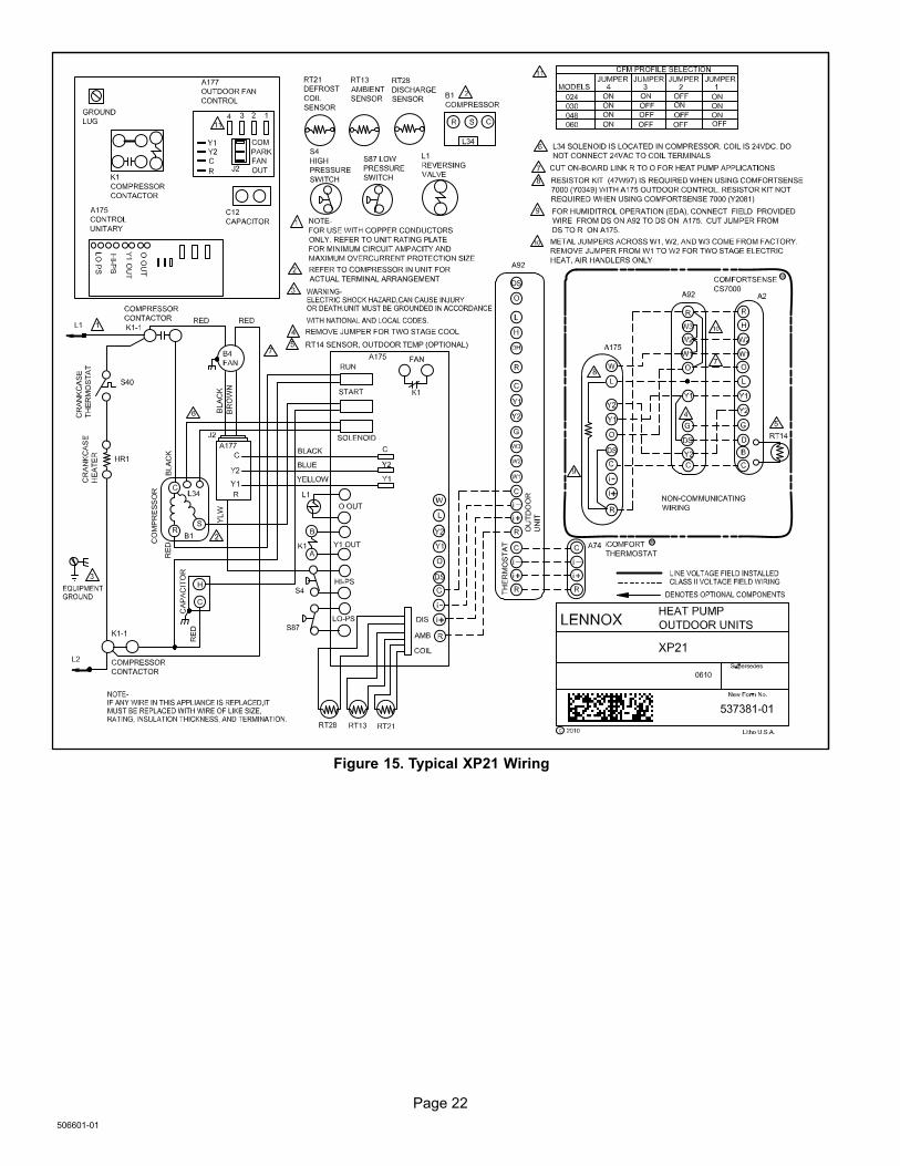
Figure 15. Typical XP21 Wiring
Page 23
XP21 SERIES
Heat Pump Control (A175) Jumpers and Terminals
55
50DEGREETARGET
45DEGREETARGET
40DEGREETARGET
55 50 45 40
SECOND−STAGE LOCK−IN TEMPERATURE
55 50 45 40
55 50 45 40
55 50 45 40
DEGREETARGET
100
90DEGREETARGET
70DEGREETARGET
*50DEGREETARGET
100
90 70 50
DEGREETARGET
DEFROST TERMINATION TEMPERATURE
100
90 70 50
100
90 70 50
100
90 70 50
30
0
COMPRESSOR SHIFT DELAY
*30
SECOND DELAY
SECOND DELAY
0
LED ALERT CODES
LED ALERT CODES
INDICATES RS−BUS DATACOMMUNICATION IS ACTIVE.(COMMUNICATION MODEONLY)
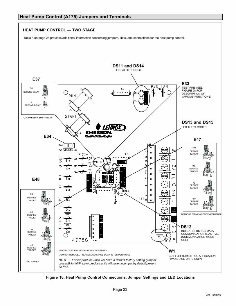
Table 3 on page 24 provides additional information concerning jumpers, links, and connections for the heat pump control.
E37
E47
DS12
E48
E34
DS11 and DS14
DS13 and DS15
JUMPER REMOVED − NO SECOND STAGE LOCK−IN TEMPERATURE.
E33TEST PINS (SEEFIGURE 28 FORDESCRIPTION OFVARIOUS FUNCTIONS)
HEAT PUMP CONTROL � TWO STAGE
CUT FOR HUMIDITROL APPLICATION(TWO−STAGE UNITS ONLY)
W1
*NO JUMPERNOTE � Earlier produce units will have a default factory setting (jumperpresent) for 40ºF. Later produce units will have no jumper by default presenton E48.
Figure 16. Heat Pump Control Connections, Jumper Settings and LED Locations

Page 24
506601−01
Table 3. Heat Pump Control (A175) Jumper and Terminal Descriptions
Control ID Label Description
E12 PSC Fan 240VAC output connection for outdoor fan.
E16 PSC Fan 240VAC input connection for outdoor fan.
E18
W 24VAC output for defrost auxiliary heat output.
L Thermostat service light connection.
Y2 24VAC thermostat input/output for second stage operation of the unit.
Y1 24VAC thermostat input for first stage operation of the unit.
O 24VAC thermostat input for reversing valve operation
DS Humiditrol Input
C 24VAC system common
i− Input/Output − RSBus data low. Used in communicating mode only with compatible indoor thermostat.
i+ Input/Output − RSBus data high. Used in communicating mode only with compatible indoor thermostat.
R 24VAC system power input
E19 and E20 O OUT 24VAC output connection for reversing valve.
E21 and E22 LO−PS Connection for low−pressure switch (2.4 milliamps @ 18VAC)
E31 and E32 Y1 OUT 24VAC common output, switched for enabling compressor contactor.
E24 and E25 HS−PS Connection for high−pressure switch.
E26 FAN 1 First−stage basic and precision dehumidification ECM fan motor 24VDC output connection 1.
E27 FAN 2 Second−stage basic and precision dehumidification ECM fan motor 24VDC output connection 2.
E28 FAN C ECM common connection for ECM fan.
E30
Six position square pin header. P4 provides connections for the temperature sensors.
DIS (YELLOW)PINS 5 and 6(RT28)
DIS 5 � Discharge line temperature sensor supply.
DIS 6 � Discharge line temperature sensor return.
Range is −35ºF to +310ºF. Sensor is clipped on a 1/2" copper tube.
AMB (BLACK)Pins 3 and 4(RT13)
AMB 3 � Outdoor ambient temperature sensor supply.
AMB 4 � Outdoor ambient temperature return.
Range is −40ºF to +140ºF
COIL (BROWN)Pins 1 and 2(RT21)
COIL 1 � Outdoor coil temperature sensor supply.
COIL 2 � Outdoor coil temperature sensor return
Range is −40ºF to +140ºF. Sensor is clipped on a 5/16" copper return bend.
E33 Field TestThis jumper allows service personnel to defeat the timed−off control, initiate or terminate a defrost cycle, andfield programming of unit capacity feature.
E34 Y2 SOLENOID Keyed plug header used for second−stage compressor output.
E37 Comp Shift Delay
Two position square pin header. When jumper is installed, a 30−second compressor shift delay is implemented.It de−energizes the compressor contactor, second−stage solenoid (if on) and the ECM fan outputs. After the timerexpires, the compressor contactor and ECM fan outputs are energized. If no jumper is installed, it changes thereversing valve direction and de−energizing the outputs immediately.
E47
50*
70
90
100
Seven position square pin header. Provides selection of the defrost terminate temperature based on the positionof the selection jumper. The defrost termination temperature is measured by the coil temperature sensor (RT21). The jumper termination pin is factory set at 50°F (10°C). If the temperature jumper is not installed, thedefault termination temperature is 90°F (32°C).
E48
55
50
45
40
NO JUMPER*
Five position square pin header. If the first−stage compressor output is active in heating mode and the outdoorambient temperature is below the selected compressor lock−in temperature, the second−stage compressorsolenoid outputs will be energized without the Y2 input. Factory default is no jumper present on E48, which setsthe control to no second stage lock−in.
NOTE � Earlier produce units will have a default factory setting (jumper present) for 40ºF. Later produce unitswill have no jumper by default present on E48.
W1 DS To RCut for Humiditrol (EDA) application. This sets the outdoor fan speed to predefined speed. See table 15 for setspeed based on unit size. Use only in two−stage units.
* Factory default setting
Page 25
XP21 SERIES
Field Control Wiring
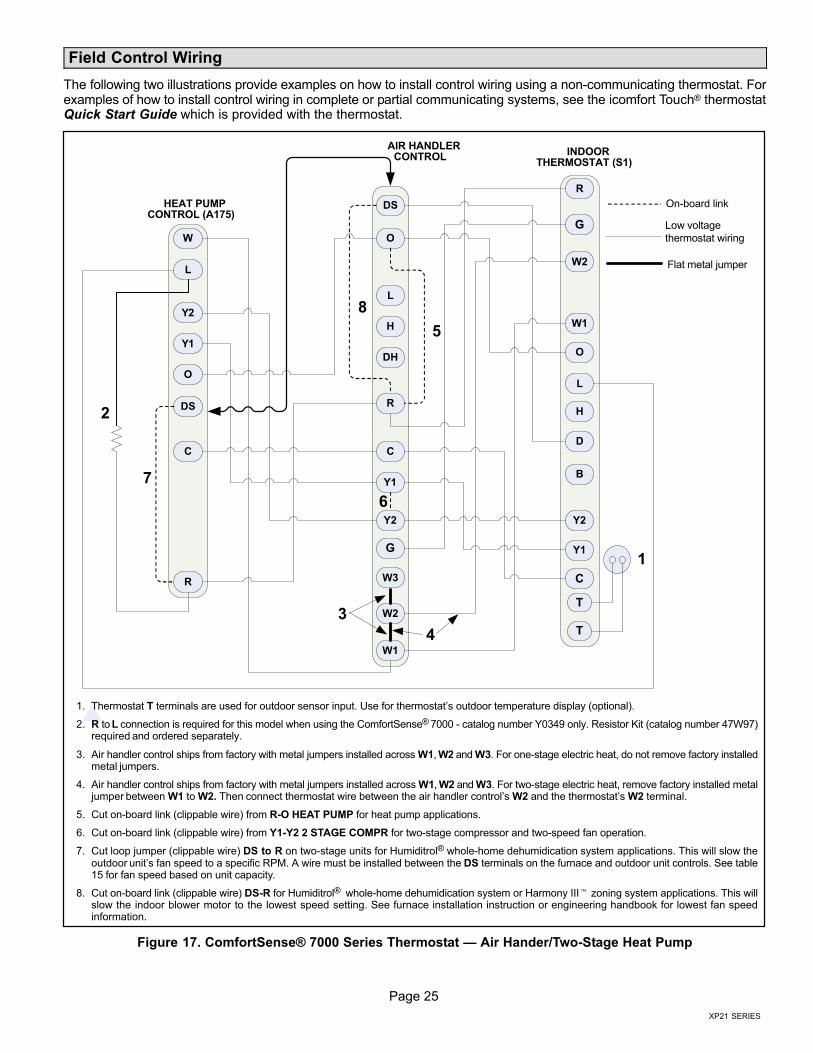
The following two illustrations provide examples on how to install control wiring using a non−communicating thermostat. Forexamples of how to install control wiring in complete or partial communicating systems, see the icomfort Touch® thermostatQuick Start Guide which is provided with the thermostat.
Y1
O
R
W1
G
D
R
Y1
L
C
C
B
Y2
Y2
W
O
DS
L
T
T
W2
H
W3
H
O
C
L
Y2
DS
DH
G
R
Y1
W2
W1
1
2
5
6
8
7
On−board link
Low voltage
thermostat wiring
Flat metal jumper
3
4
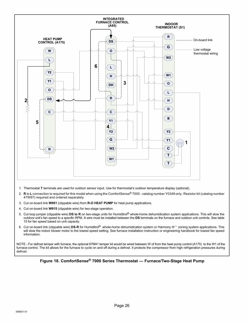
1. Thermostat T terminals are used for outdoor sensor input. Use for thermostat’s outdoor temperature display (optional).
2. R to L connection is required for this model when using the ComfortSense® 7000 − catalog number Y0349 only. Resistor Kit (catalog number 47W97)required and ordered separately.
3. Air handler control ships from factory with metal jumpers installed across W1, W2 and W3. For one−stage electric heat, do not remove factory installedmetal jumpers.
4. Air handler control ships from factory with metal jumpers installed across W1, W2 and W3. For two−stage electric heat, remove factory installed metaljumper between W1 to W2. Then connect thermostat wire between the air handler control’s W2 and the thermostat’s W2 terminal.
5. Cut on−board link (clippable wire) from R−O HEAT PUMP for heat pump applications.
6. Cut on−board link (clippable wire) from Y1−Y2 2 STAGE COMPR for two−stage compressor and two−speed fan operation.
7. Cut loop jumper (clippable wire) DS to R on two−stage units for Humiditrol® whole−home dehumidication system applications. This will slow theoutdoor unit’s fan speed to a specific RPM. A wire must be installed between the DS terminals on the furnace and outdoor unit controls. See table15 for fan speed based on unit capacity.
8. Cut on−board link (clippable wire) DS−R for Humiditrol® whole−home dehumidication system or Harmony III� zoning system applications. This willslow the indoor blower motor to the lowest speed setting. See furnace installation instruction or engineering handbook for lowest fan speedinformation.
HEAT PUMPCONTROL (A175)
AIR HANDLERCONTROL
INDOORTHERMOSTAT (S1)
Figure 17. ComfortSense® 7000 Series Thermostat � Air Hander/Two−Stage Heat Pump
Page 26
506601−01
Y1
O
R
W1
G
D
R
Y1
L
C
C
HEAT PUMPCONTROL (A175)
B
Y2
Y2
W
O
DS
L
T
T
W2
H
H
O
C
L
Y2
DS
DH
G
R
Y1
W2
W1
1
2
3
4
6
5
On−board link
Low voltage
thermostat wiring
1. Thermostat T terminals are used for outdoor sensor input. Use for thermostat’s outdoor temperature display (optional).
2. R to L connection is required for this model when using the ComfortSense® 7000 − catalog number Y0349 only. Resistor kit (catalog number47W97) required and ordered separately.
3. Cut on−board link W951 (clippable wire) from R−O HEAT PUMP for heat pump applications.
4. Cut on−board link W915 (clippable wire) for two−stage operation.
5. Cut loop jumper (clippable wire) DS to R on two−stage units for Humiditrol® whole−home dehumidication system applications. This will slow theoutdoor unit’s fan speed to a specific RPM. A wire must be installed between the DS terminals on the furnace and outdoor unit controls. See table15 for fan speed based on unit capacity.
6. Cut on−board link (clippable wire) DS−R for Humiditrol® whole−home dehumidication system or Harmony III� zoning system applications. Thiswill slow the indoor blower motor to the lowest speed setting. See furnace installation instruction or engineering handbook for lowest fan speedinformation.
INTEGRATEDFURNACE CONTROL
(A95)INDOOR
THERMOSTAT (S1)
NOTE − For defrost temper with furnace, the optional 67M41 temper kit would be wired between W of from the heat pump control (A175) to the W1 of thefurnace control. The kit allows for the furnace to cycle on and off during a defrost. It protects the compressor from high refrigeration pressures duringdefrost.
Figure 18. ComfortSense® 7000 Series Thermostat � Furnace/Two−Stage Heat Pump
Page 27
XP21 SERIES
Servicing Units Delivered Void of Charge
If the outdoor unit is void of refrigerant, clean the systemusing the procedure described below.
1. Leak check system using procedure outlined on page18.
2. Evacuate the system using procedure outlined onpage .
3. Use nitrogen to break the vacuum and install a newfilter drier in the system.
4. Evacuate the system again using procedure outlinedon page .
5. Weigh in refrigerant using procedure outlined in figure21.
6. Monitor the system to determine the amount ofmoisture remaining in the oil. It may be necessary toreplace the filter drier several times to achieve therequired dryness level. If system dryness is notverified, the compressor will fail in the future.
Unit Start−Up
IMPORTANTIf unit is equipped with a crankcase heater, it should beenergized 24 hours before unit start−up to preventcompressor damage as a result of slugging.
1. Rotate fan to check for binding.
2. Inspect all factory− and field−installed wiring for looseconnections.
3. After evacuation is complete, open both the liquid andvapor line service valves to release the refrigerantcharge contained in outdoor unit into the system.
4. Replace the stem caps and tighten to the value listedin table 1.
5. Check voltage supply at the disconnect switch. Thevoltage must be within the range listed on the unit’snameplate. If not, do not start the equipment until youhave consulted with the power company and thevoltage condition has been corrected.
6. Set the thermostat for a cooling demand. Turn onpower to the indoor indoor unit and close the outdoorunit disconnect switch to start the unit.
7. Recheck voltage while the unit is running. Power mustbe within range shown on the nameplate.
8. Check system for sufficient refrigerant by using theprocedures listed under System Refrigerant.
System Refrigerant
This section outlines procedures for:
1. Connecting gauge set for testing and charging asillustrated in figure 19.
2. Checking and adjusting indoor airflow as described infigure 20.
3. Add or remove refrigerant using the weigh in methodprovided in figure 21, and verifying charge usingsubcooling method described in figure 22.
TO LIQUIDLINE SERVICE
VALVETEMPERATURESENSOR
DIGITAL SCALE
REFRIGERANT TANK
TEMPERATURE SENSOR(LIQUID LINE)
MANIFOLD GAUGE SET
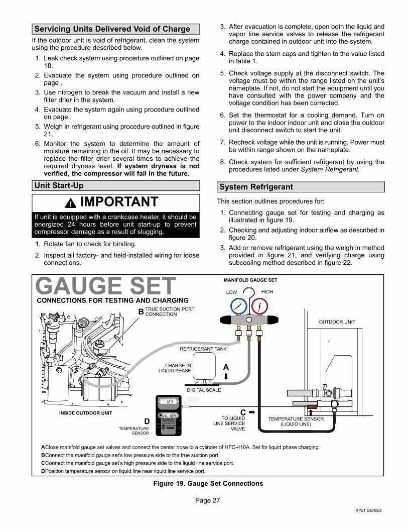
AClose manifold gauge set valves and connect the center hose to a cylinder of HFC−410A. Set for liquid phase charging.
BConnect the manifold gauge set’s low pressure side to the true suction port.
CConnect the manifold gauge set’s high pressure side to the liquid line service port.
DPosition temperature sensor on liquid line near liquid line service port.
OUTDOOR UNIT
CHARGE INLIQUID PHASE
CONNECTIONS FOR TESTING AND CHARGING
GAUGE SET
A
CD
LOW HIGH
B
INSIDE OUTDOOR UNIT
TRUE SUCTION PORTCONNECTION
Figure 19. Gauge Set Connections
Page 28
506601−01
ADDING OR REMOVING REFRIGERANT
This system uses HFC−410A refrigerant which operates atmuch higher pressures than HCFC−22. The pre−installedliquid line filter drier is approved for use with HFC−410Aonly. Do not replace it with components designed for usewith HCFC−22.
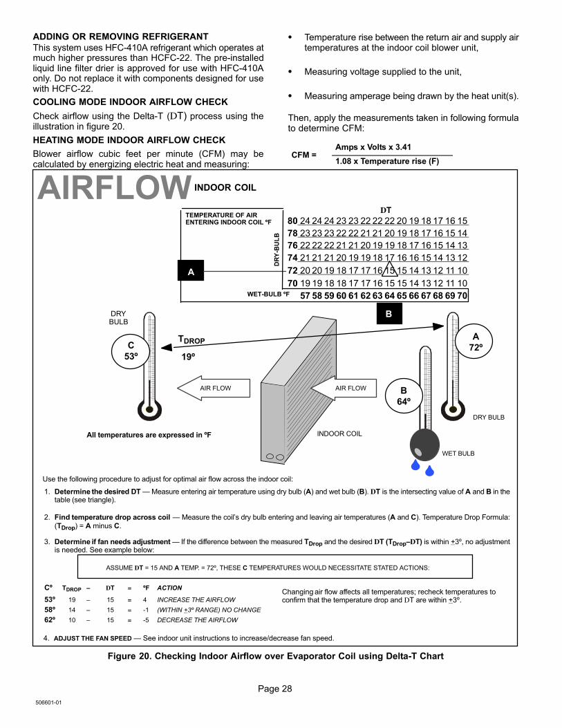
COOLING MODE INDOOR AIRFLOW CHECK
Check airflow using the Delta−T (DT) process using theillustration in figure 20.
HEATING MODE INDOOR AIRFLOW CHECK
Blower airflow cubic feet per minute (CFM) may becalculated by energizing electric heat and measuring:
� Temperature rise between the return air and supply airtemperatures at the indoor coil blower unit,
� Measuring voltage supplied to the unit,
� Measuring amperage being drawn by the heat unit(s).
Then, apply the measurements taken in following formulato determine CFM:
CFM =Amps x Volts x 3.41
1.08 x Temperature rise (F)
Cº TDROP – DT = ºF ACTION
53º 19 – 15 = 4 INCREASE THE AIRFLOW
58º 14 – 15 = −1 (WITHIN +3º RANGE) NO CHANGE
62º 10 – 15 = −5 DECREASE THE AIRFLOW
DT
80 24 24 24 23 23 22 22 22 20 19 18 17 16 15
78 23 23 23 22 22 21 21 20 19 18 17 16 15 14
76 22 22 22 21 21 20 19 19 18 17 16 15 14 13
74 21 21 21 20 19 19 18 17 16 16 15 14 13 12
72 20 20 19 18 17 17 16 15 15 14 13 12 11 10
70 19 19 18 18 17 17 16 15 15 14 13 12 11 10
57 58 59 60 61 62 63 64 65 66 67 68 69 70
TEMPERATURE OF AIRENTERING INDOOR COIL ºF
INDOOR COIL
DRY BULB
DRYBULB
WET BULB
B
TDROP
19º
AD
RY
−BU
LB
WET−BULB ºF
A
72º
B
64º
C
53º
AIR FLOWAIR FLOW
All temperatures are expressed in ºF
1. Determine the desired DT � Measure entering air temperature using dry bulb (A) and wet bulb (B). DT is the intersecting value of A and B in thetable (see triangle).
2. Find temperature drop across coil � Measure the coil’s dry bulb entering and leaving air temperatures (A and C). Temperature Drop Formula:(TDrop) = A minus C.
3. Determine if fan needs adjustment � If the difference between the measured TDrop and the desired DT (TDrop–DT) is within +3º, no adjustmentis needed. See example below:
4. ADJUST THE FAN SPEED � See indoor unit instructions to increase/decrease fan speed.
ASSUME DT = 15 AND A TEMP. = 72º, THESE C TEMPERATURES WOULD NECESSITATE STATED ACTIONS:
AIRFLOW
Use the following procedure to adjust for optimal air flow across the indoor coil:
INDOOR COIL
Changing air flow affects all temperatures; recheck temperatures toconfirm that the temperature drop and DT are within +3º.
Figure 20. Checking Indoor Airflow over Evaporator Coil using Delta−T Chart
Page 29
XP21 SERIES
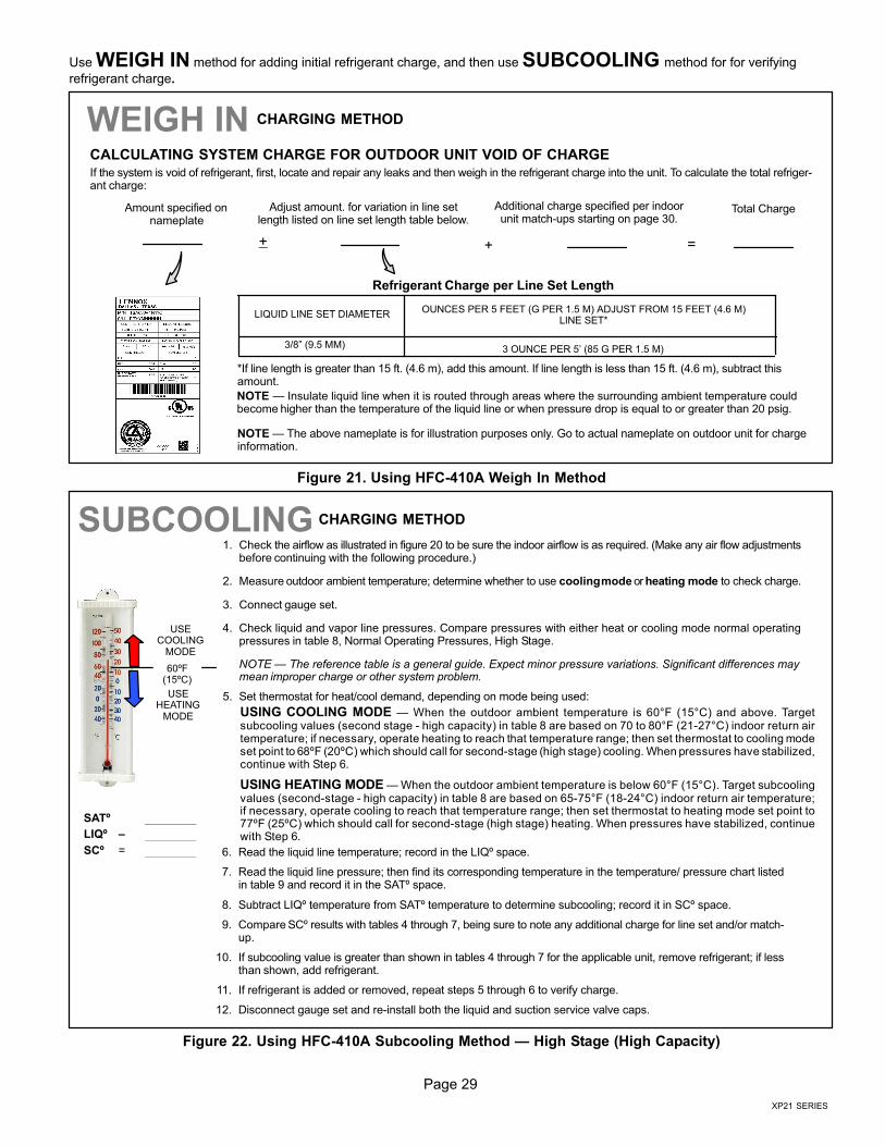
Use WEIGH IN method for adding initial refrigerant charge, and then use SUBCOOLING method for for verifying
refrigerant charge.
WEIGH IN
LIQUID LINE SET DIAMETEROUNCES PER 5 FEET (G PER 1.5 M) ADJUST FROM 15 FEET (4.6 M)
LINE SET*
3/8" (9.5 MM) 3 OUNCE PER 5’ (85 G PER 1.5 M)
*If line length is greater than 15 ft. (4.6 m), add this amount. If line length is less than 15 ft. (4.6 m), subtract thisamount.
Refrigerant Charge per Line Set Length
NOTE � The above nameplate is for illustration purposes only. Go to actual nameplate on outdoor unit for chargeinformation.
CHARGING METHOD
NOTE � Insulate liquid line when it is routed through areas where the surrounding ambient temperature couldbecome higher than the temperature of the liquid line or when pressure drop is equal to or greater than 20 psig.
CALCULATING SYSTEM CHARGE FOR OUTDOOR UNIT VOID OF CHARGE
If the system is void of refrigerant, first, locate and repair any leaks and then weigh in the refrigerant charge into the unit. To calculate the total refriger-ant charge:
Amount specified onnameplate
Adjust amount. for variation in line setlength listed on line set length table below.
Additional charge specified per indoorunit match−ups starting on page 30.
Total Charge
+ + =
Figure 21. Using HFC−410A Weigh In Method
1. Check the airflow as illustrated in figure 20 to be sure the indoor airflow is as required. (Make any air flow adjustmentsbefore continuing with the following procedure.)
2. Measure outdoor ambient temperature; determine whether to use cooling mode or heating mode to check charge.
3. Connect gauge set.
4. Check liquid and vapor line pressures. Compare pressures with either heat or cooling mode normal operatingpressures in table 8, Normal Operating Pressures, High Stage.
NOTE � The reference table is a general guide. Expect minor pressure variations. Significant differences maymean improper charge or other system problem.
5. Set thermostat for heat/cool demand, depending on mode being used:
USECOOLING
MODE
USEHEATING
MODE
60ºF(15ºC)
SATº
LIQº –
SCº =
SUBCOOLING
6. Read the liquid line temperature; record in the LIQº space.
7. Read the liquid line pressure; then find its corresponding temperature in the temperature/ pressure chart listedin table 9 and record it in the SATº space.
8. Subtract LIQº temperature from SATº temperature to determine subcooling; record it in SCº space.
9. Compare SCº results with tables 4 through 7, being sure to note any additional charge for line set and/or match−up.
10. If subcooling value is greater than shown in tables 4 through 7 for the applicable unit, remove refrigerant; if lessthan shown, add refrigerant.
11. If refrigerant is added or removed, repeat steps 5 through 6 to verify charge.
12. Disconnect gauge set and re−install both the liquid and suction service valve caps.
USING COOLING MODE � When the outdoor ambient temperature is 60°F (15°C) and above. Targetsubcooling values (second stage − high capacity) in table 8 are based on 70 to 80°F (21−27°C) indoor return airtemperature; if necessary, operate heating to reach that temperature range; then set thermostat to cooling modeset point to 68ºF (20ºC) which should call for second−stage (high stage) cooling. When pressures have stabilized,continue with Step 6.
USING HEATING MODE � When the outdoor ambient temperature is below 60°F (15°C). Target subcoolingvalues (second−stage − high capacity) in table 8 are based on 65−75°F (18−24°C) indoor return air temperature;if necessary, operate cooling to reach that temperature range; then set thermostat to heating mode set point to77ºF (25ºC) which should call for second−stage (high stage) heating. When pressures have stabilized, continuewith Step 6.
CHARGING METHOD
Figure 22. Using HFC−410A Subcooling Method � High Stage (High Capacity)
Page 30
506601−01
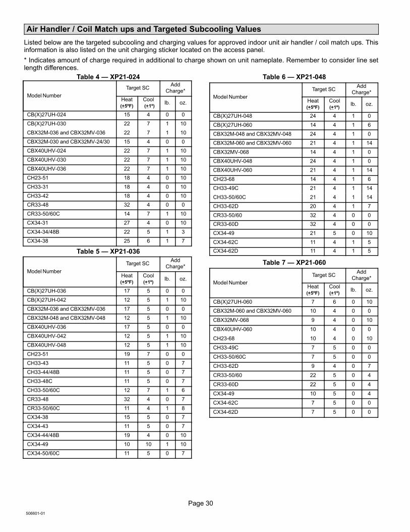
Air Handler / Coil Match ups and Targeted Subcooling Values
Listed below are the targeted subcooling and charging values for approved indoor unit air handler / coil match ups. Thisinformation is also listed on the unit charging sticker located on the access panel.
* Indicates amount of charge required in additional to charge shown on unit nameplate. Remember to consider line setlength differences.
Table 4 � XP21−024
Model Number
Target SCAdd
Charge*
Heat(+5ºF)
Cool�(+1º)
lb. oz.
CB(X)27UH−024 15 4 0 0
CB(X)27UH−030 22 7 1 10
CBX32M−036 and CBX32MV−036 22 7 1 10
CBX32M−030 and CBX32MV−24/30 15 4 0 0
CBX40UHV−024 22 7 1 10
CBX40UHV−030 22 7 1 10
CBX40UHV−036 22 7 1 10
CH23−51 18 4 0 10
CH33−31 18 4 0 10
CH33−42 18 4 0 10
CR33−48 32 4 0 0
CR33−50/60C 14 7 1 10
CX34−31 27 4 0 10
CX34−34/48B 22 5 1 3
CX34−38 25 6 1 7
Table 5 � XP21−036
Model Number
Target SCAdd
Charge*
Heat(+5ºF)
Cool(+1º)
lb. oz.
CB(X)27UH−036 17 5 0 0
CB(X)27UH−042 12 5 1 10
CBX32M−036 and CBX32MV−036 17 5 0 0
CBX32M−048 and CBX32MV−048 12 5 1 10
CBX40UHV−036 17 5 0 0
CBX40UHV−042 12 5 1 10
CBX40UHV−048 12 5 1 10
CH23−51 19 7 0 0
CH33−43 11 5 0 7
CH33−44/48B 11 5 0 7
CH33−48C 11 5 0 7
CH33−50/60C 12 7 1 6
CR33−48 32 4 0 7
CR33−50/60C 11 4 1 8
CX34−38 15 5 0 7
CX34−43 11 5 0 7
CX34−44/48B 19 4 0 10
CX34−49 10 10 1 10
CX34−50/60C 11 5 0 7
Table 6 � XP21−048
Model Number
Target SCAdd
Charge*
Heat(+5ºF)
Cool(+1º)
lb. oz.
CB(X)27UH−048 24 4 1 0
CB(X)27UH−060 14 4 1 6
CBX32M−048 and CBX32MV−048 24 4 1 0
CBX32M−060 and CBX32MV−060 21 4 1 14
CBX32MV−068 14 4 1 0
CBX40UHV−048 24 4 1 0
CBX40UHV−060 21 4 1 14
CH23−68 14 4 1 6
CH33−49C 21 4 1 14
CH33−50/60C 21 4 1 14
CH33−62D 20 4 1 7
CR33−50/60 32 4 0 0
CR33−60D 32 4 0 0
CX34−49 21 5 0 10
CX34−62C 11 4 1 5
CX34−62D 11 4 1 5
Table 7 � XP21−060
Model Number
Target SCAdd
Charge*
Heat(+5ºF)
Cool(+1º)
lb. oz.
CB(X)27UH−060 7 6 0 10
CBX32M−060 and CBX32MV−060 10 4 0 0
CBX32MV−068 9 4 0 10
CBX40UHV−060 10 4 0 0
CH23−68 10 4 0 10
CH33−49C 7 5 0 0
CH33−50/60C 7 5 0 0
CH33−62D 9 4 0 7
CR33−50/60 22 5 0 4
CR33−60D 22 5 0 4
CX34−49 10 5 0 4
CX34−62C 7 5 0 0
CX34−62D 7 5 0 0
Page 31
XP21 SERIES
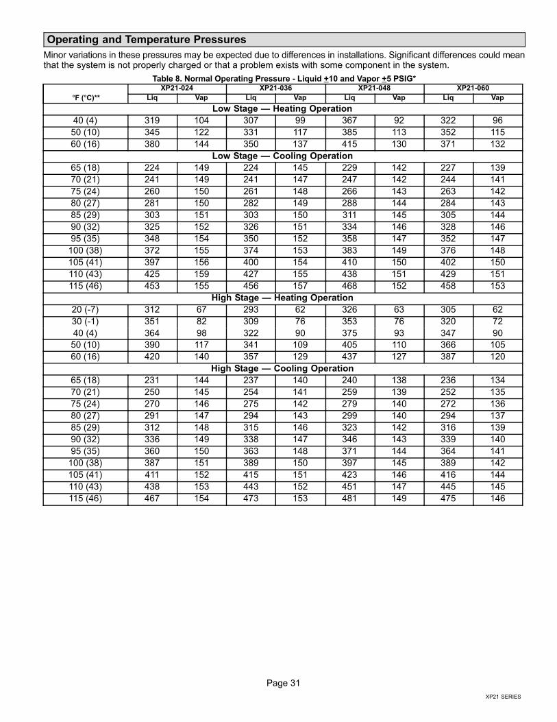
Operating and Temperature Pressures
Minor variations in these pressures may be expected due to differences in installations. Significant differences could meanthat the system is not properly charged or that a problem exists with some component in the system.
Table 8. Normal Operating Pressure − Liquid +10 and Vapor +5 PSIG*
�F (�C)**
XP21−024 XP21−036 XP21−048 XP21−060
Liq Vap Liq Vap Liq Vap Liq Vap
Low Stage � Heating Operation
40 (4) 319 104 307 99 367 92 322 96
50 (10) 345 122 331 117 385 113 352 115
60 (16) 380 144 350 137 415 130 371 132
Low Stage � Cooling Operation
65 (18) 224 149 224 145 229 142 227 139
70 (21) 241 149 241 147 247 142 244 141
75 (24) 260 150 261 148 266 143 263 142
80 (27) 281 150 282 149 288 144 284 143
85 (29) 303 151 303 150 311 145 305 144
90 (32) 325 152 326 151 334 146 328 146
95 (35) 348 154 350 152 358 147 352 147
100 (38) 372 155 374 153 383 149 376 148
105 (41) 397 156 400 154 410 150 402 150
110 (43) 425 159 427 155 438 151 429 151
115 (46) 453 155 456 157 468 152 458 153
High Stage � Heating Operation
20 (−7) 312 67 293 62 326 63 305 62
30 (−1) 351 82 309 76 353 76 320 72
40 (4) 364 98 322 90 375 93 347 90
50 (10) 390 117 341 109 405 110 366 105
60 (16) 420 140 357 129 437 127 387 120
High Stage � Cooling Operation
65 (18) 231 144 237 140 240 138 236 134
70 (21) 250 145 254 141 259 139 252 135
75 (24) 270 146 275 142 279 140 272 136
80 (27) 291 147 294 143 299 140 294 137
85 (29) 312 148 315 146 323 142 316 139
90 (32) 336 149 338 147 346 143 339 140
95 (35) 360 150 363 148 371 144 364 141
100 (38) 387 151 389 150 397 145 389 142
105 (41) 411 152 415 151 423 146 416 144
110 (43) 438 153 443 152 451 147 445 145
115 (46) 467 154 473 153 481 149 475 146
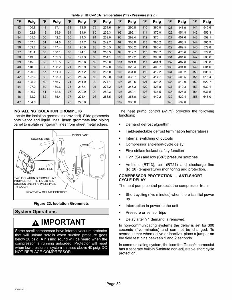
Page 32
506601−01
Table 9. HFC−410A Temperature (°F) − Pressure (Psig)
°F Psig °F Psig °F Psig °F Psig °F Psig °F Psig °F Psig °F Psig
32 100.8 48 137.1 63 178.5 79 231.6 94 290.8 110 365.0 125 445.9 141 545.6
33 102.9 49 139.6 64 181.6 80 235.3 95 295.1 111 370.0 126 451.8 142 552.3
34 105.0 50 142.2 65 184.3 81 239.0 96 299.4 112 375.1 127 457.6 143 559.1
35 107.1 51 144.8 66 187.7 82 242.7 97 303.8 113 380.2 128 463.5 144 565.9
36 109.2 52 147.4 67 190.9 83 246.5 98 308.2 114 385.4 129 469.5 145 572.8
37 111.4 53 150.1 68 194.1 84 250.3 99 312.7 115 390.7 130 475.6 146 579.8
38 113.6 54 152.8 69 197.3 85 254.1 100 317.2 116 396.0 131 481.6 147 586.8
39 115.8 55 155.5 70 200.6 86 258.0 101 321.8 117 401.3 132 487.8 148 593.8
40 118.0 56 158.2 71 203.9 87 262.0 102 326.4 118 406.7 133 494.0 149 601.0
41 120.3 57 161.0 72 207.2 88 266.0 103 331.0 119 412.2 134 500.2 150 608.1
42 122.6 58 163.9 73 210.6 89 270.0 104 335.7 120 417.7 135 506.5 151 615.4
43 125.0 59 166.7 74 214.0 90 274.1 105 340.5 121 423.2 136 512.9 152 622.7
44 127.3 60 169.6 75 217.4 91 278.2 106 345.3 122 428.8 137 519.3 153 630.1
45 129.7 61 172.6 76 220.9 92 282.3 107 350.1 123 434.5 138 525.8 154 637.5
46 132.2 62 175.4 77 224.4 93 286.5 108 355.0 124 440.2 139 532.4 155 645.0
47 134.6 78 228.0 109 360.0 140 539.0
INSTALLING ISOLATION GROMMETS
Locate the isolation grommets (provided). Slide grommetsonto vapor and liquid lines. Insert grommets into pipingpanel to isolate refrigerant lines from sheet metal edges.
TWO ISOLATION GROMMETS AREPROVIDE FOR THE LIQUID ANDSUCTION LINE PIPE PANEL PASSTHROUGH.
LIQUID LINE
SUCTION LINE
REAR VIEW OF UNIT EXTERIOR
PIPING PANEL
Figure 23. Isolation Grommets
System Operations
IMPORTANTSome scroll compressor have internal vacuum protectorthat will unload scrolls when suction pressure goesbelow 20 psig. A hissing sound will be heard when thecompressor is running unloaded. Protector will resetwhen low pressure in system is raised above 40 psig. DONOT REPLACE COMPRESSOR.
The heat pump control (A175) provides the followingfunctions:
� Demand defrost algorithm
� Field−selectable defrost termination temperatures
� Internal switching of outputs
� Compressor anti−short−cycle delay.
� Five−strikes lockout safety function
� High (S4) and low (S87) pressure switches
� Ambient (RT13), coil (RT21) and discharge line
(RT28) temperatures monitoring and protection.
COMPRESSOR PROTECTION � ANTI−SHORTCYCLE DELAY
The heat pump control protects the compressor from:
� Short cycling (five minutes) when there is initial powerup
� Interruption in power to the unit
� Pressure or sensor trips
� Delay after Y1 demand is removed.
In non−communicating systems the delay is set for 300seconds (five minutes) and can not be changed. Tooverride timer when active or inactive, place a jumper onthe field test pins between 1 and 2 seconds.
In communicating system, the icomfort Touch® thermostathas a separate built−in 5−minute non−adjustable short cycleprotection.
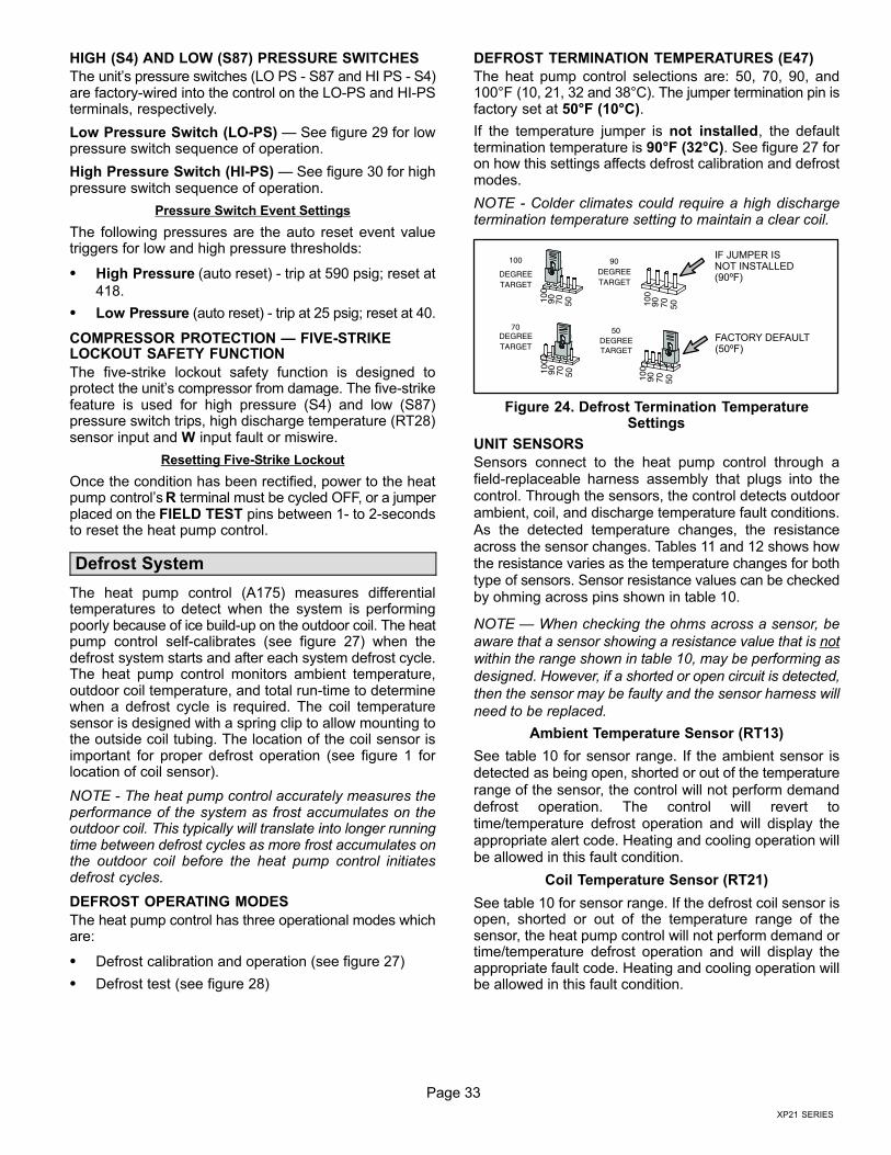
Page 33
XP21 SERIES
HIGH (S4) AND LOW (S87) PRESSURE SWITCHES
The unit’s pressure switches (LO PS − S87 and HI PS − S4)are factory−wired into the control on the LO−PS and HI−PSterminals, respectively.
Low Pressure Switch (LO−PS) � See figure 29 for lowpressure switch sequence of operation.
High Pressure Switch (HI−PS) � See figure 30 for highpressure switch sequence of operation.
Pressure Switch Event Settings
The following pressures are the auto reset event valuetriggers for low and high pressure thresholds:
� High Pressure (auto reset) − trip at 590 psig; reset at
418.
� Low Pressure (auto reset) − trip at 25 psig; reset at 40.
COMPRESSOR PROTECTION � FIVE−STRIKELOCKOUT SAFETY FUNCTION
The five−strike lockout safety function is designed toprotect the unit’s compressor from damage. The five−strikefeature is used for high pressure (S4) and low (S87)pressure switch trips, high discharge temperature (RT28)sensor input and W input fault or miswire.
Resetting Five−Strike Lockout
Once the condition has been rectified, power to the heatpump control’s R terminal must be cycled OFF, or a jumperplaced on the FIELD TEST pins between 1− to 2−secondsto reset the heat pump control.
Defrost System
The heat pump control (A175) measures differentialtemperatures to detect when the system is performingpoorly because of ice build−up on the outdoor coil. The heatpump control self−calibrates (see figure 27) when thedefrost system starts and after each system defrost cycle.The heat pump control monitors ambient temperature,outdoor coil temperature, and total run−time to determinewhen a defrost cycle is required. The coil temperaturesensor is designed with a spring clip to allow mounting tothe outside coil tubing. The location of the coil sensor isimportant for proper defrost operation (see figure 1 forlocation of coil sensor).
NOTE − The heat pump control accurately measures theperformance of the system as frost accumulates on theoutdoor coil. This typically will translate into longer runningtime between defrost cycles as more frost accumulates onthe outdoor coil before the heat pump control initiatesdefrost cycles.
DEFROST OPERATING MODES
The heat pump control has three operational modes whichare:
� Defrost calibration and operation (see figure 27)
� Defrost test (see figure 28)
DEFROST TERMINATION TEMPERATURES (E47)
The heat pump control selections are: 50, 70, 90, and100°F (10, 21, 32 and 38°C). The jumper termination pin isfactory set at 50°F (10°C).
If the temperature jumper is not installed, the defaulttermination temperature is 90°F (32°C). See figure 27 foron how this settings affects defrost calibration and defrostmodes.
NOTE − Colder climates could require a high dischargetermination temperature setting to maintain a clear coil.
100 90DEGREETARGET
70DEGREETARGET
50DEGREETARGET
100
90 70 50
DEGREETARGET
100
90 70 50
100
90 70 50
100
90 70 50
FACTORY DEFAULT(50ºF)
IF JUMPER ISNOT INSTALLED(90ºF)
Figure 24. Defrost Termination TemperatureSettings
UNIT SENSORS
Sensors connect to the heat pump control through afield-replaceable harness assembly that plugs into thecontrol. Through the sensors, the control detects outdoorambient, coil, and discharge temperature fault conditions.
As the detected temperature changes, the resistanceacross the sensor changes. Tables 11 and 12 shows howthe resistance varies as the temperature changes for bothtype of sensors. Sensor resistance values can be checkedby ohming across pins shown in table 10.
NOTE � When checking the ohms across a sensor, be
aware that a sensor showing a resistance value that is not
within the range shown in table 10, may be performing as
designed. However, if a shorted or open circuit is detected,
then the sensor may be faulty and the sensor harness will
need to be replaced.
Ambient Temperature Sensor (RT13)
See table 10 for sensor range. If the ambient sensor isdetected as being open, shorted or out of the temperature
range of the sensor, the control will not perform demanddefrost operation. The control will revert totime/temperature defrost operation and will display theappropriate alert code. Heating and cooling operation willbe allowed in this fault condition.
Coil Temperature Sensor (RT21)
See table 10 for sensor range. If the defrost coil sensor isopen, shorted or out of the temperature range of thesensor, the heat pump control will not perform demand ortime/temperature defrost operation and will display theappropriate fault code. Heating and cooling operation willbe allowed in this fault condition.
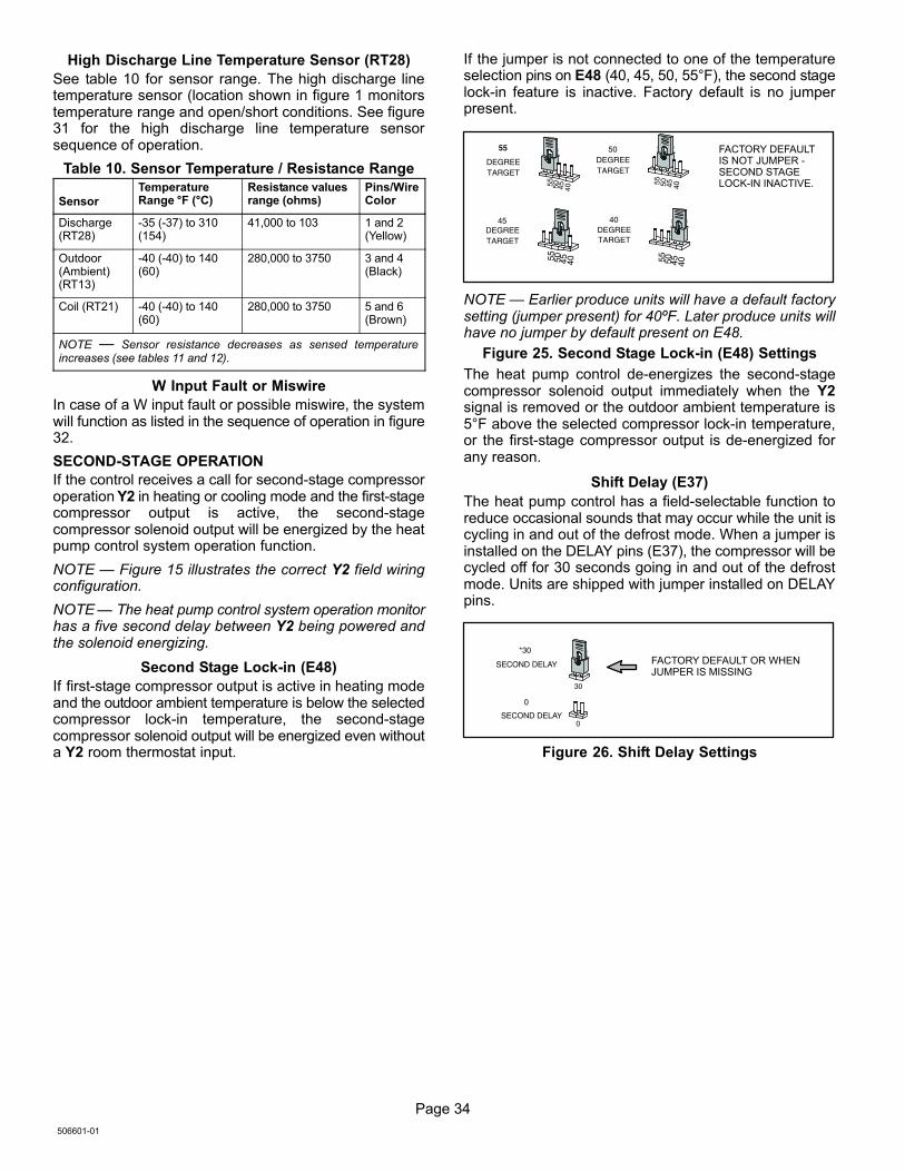
Page 34
506601−01
High Discharge Line Temperature Sensor (RT28)
See table 10 for sensor range. The high discharge linetemperature sensor (location shown in figure 1 monitorstemperature range and open/short conditions. See figure31 for the high discharge line temperature sensorsequence of operation.
Table 10. Sensor Temperature / Resistance Range
Sensor
TemperatureRange °F (°C)
Resistance valuesrange (ohms)
Pins/WireColor
Discharge(RT28)
−35 (−37) to 310(154)
41,000 to 103 1 and 2(Yellow)
Outdoor(Ambient)(RT13)
−40 (−40) to 140(60)
280,000 to 3750 3 and 4(Black)
Coil (RT21) −40 (−40) to 140(60)
280,000 to 3750 5 and 6(Brown)
NOTE � Sensor resistance decreases as sensed temperatureincreases (see tables 11 and 12).
W Input Fault or Miswire
In case of a W input fault or possible miswire, the systemwill function as listed in the sequence of operation in figure32.
SECOND−STAGE OPERATION
If the control receives a call for second−stage compressoroperation Y2 in heating or cooling mode and the first-stagecompressor output is active, the second-stagecompressor solenoid output will be energized by the heatpump control system operation function.
NOTE � Figure 15 illustrates the correct Y2 field wiringconfiguration.
NOTE � The heat pump control system operation monitorhas a five second delay between Y2 being powered andthe solenoid energizing.
Second Stage Lock−in (E48)
If first-stage compressor output is active in heating modeand the outdoor ambient temperature is below the selectedcompressor lock−in temperature, the second-stagecompressor solenoid output will be energized even withouta Y2 room thermostat input.
If the jumper is not connected to one of the temperatureselection pins on E48 (40, 45, 50, 55°F), the second stagelock−in feature is inactive. Factory default is no jumperpresent.
FACTORY DEFAULTIS NOT JUMPER −SECOND STAGELOCK−IN INACTIVE.
55 50DEGREETARGET
45DEGREETARGET
40DEGREETARGET
55 50 45 40
55 50 45 40
55 50 45 40
55 50 45 40
DEGREETARGET
NOTE � Earlier produce units will have a default factorysetting (jumper present) for 40ºF. Later produce units willhave no jumper by default present on E48.
Figure 25. Second Stage Lock−in (E48) Settings
The heat pump control de−energizes the second-stagecompressor solenoid output immediately when the Y2signal is removed or the outdoor ambient temperature is5°F above the selected compressor lock−in temperature,or the first-stage compressor output is de−energized forany reason.
Shift Delay (E37)
The heat pump control has a field−selectable function toreduce occasional sounds that may occur while the unit iscycling in and out of the defrost mode. When a jumper isinstalled on the DELAY pins (E37), the compressor will becycled off for 30 seconds going in and out of the defrostmode. Units are shipped with jumper installed on DELAYpins.
FACTORY DEFAULT OR WHENJUMPER IS MISSING
30
0
*30
SECOND DELAY
SECOND DELAY
0
Figure 26. Shift Delay Settings
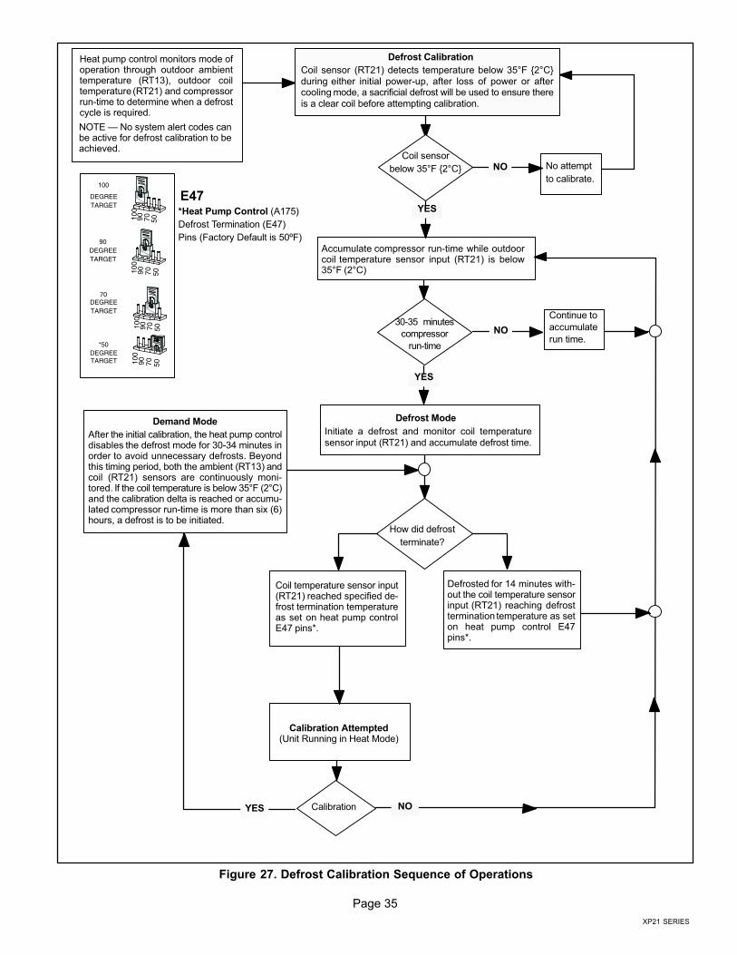
Page 35
XP21 SERIES
Continue to
accumulate
run time.
Heat pump control monitors mode ofoperation through outdoor ambienttemperature (RT13), outdoor coiltemperature (RT21) and compressorrun−time to determine when a defrostcycle is required.
Defrost Calibration
Defrost Mode
Coil temperature sensor input(RT21) reached specified de-frost termination temperatureas set on heat pump controlE47 pins*.
Calibration Attempted(Unit Running in Heat Mode)
Calibration
Demand Mode
After the initial calibration, the heat pump controldisables the defrost mode for 30−34 minutes inorder to avoid unnecessary defrosts. Beyondthis timing period, both the ambient (RT13) andcoil (RT21) sensors are continuously moni-tored. If the coil temperature is below 35°F (2°C)and the calibration delta is reached or accumu-lated compressor run−time is more than six (6)hours, a defrost is to be initiated.
100
90DEGREETARGET
70DEGREETARGET
*50DEGREETARGET 10
090 70 50
DEGREETARGET
100
90 70 50
100
90 70 50
100
90 70 50
E47*Heat Pump Control (A175)
Defrost Termination (E47)
Pins (Factory Default is 50ºF)
Coil sensor
below 35°F {2°C} No attempt
to calibrate.
30−35 minutes
compressor
run−time
Accumulate compressor run−time while outdoorcoil temperature sensor input (RT21) is below35°F (2°C)
Defrosted for 14 minutes with-out the coil temperature sensorinput (RT21) reaching defrosttermination temperature as seton heat pump control E47pins*.
How did defrost
terminate?
NO
NO
YES
YES
NO
Coil sensor (RT21) detects temperature below 35°F {2°C}during either initial power−up, after loss of power or aftercooling mode, a sacrificial defrost will be used to ensure thereis a clear coil before attempting calibration.
Initiate a defrost and monitor coil temperaturesensor input (RT21) and accumulate defrost time.
YES
NOTE � No system alert codes canbe active for defrost calibration to beachieved.
Figure 27. Defrost Calibration Sequence of Operations
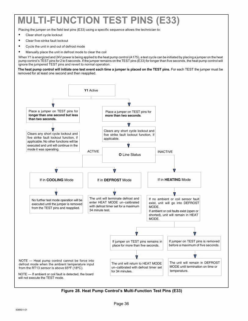
Page 36
506601−01
MULTI−FUNCTION TEST PINS (E33)Placing the jumper on the field test pins (E33) using a specific sequence allows the technician to:
� Clear short cycle lockout
� Clear five−strike fault lockout
� Cycle the unit in and out of defrost mode
� Manually place the unit in defrost mode to clear the coil
When Y1 is energized and 24V power is being applied to the heat pump control (A175), a test cycle can be initiated by placing a jumper on the heatpump control’s TEST pins for 2 to 5 seconds. If the jumper remains on the TEST pins (E33) for longer than five seconds, the heat pump control willignore the jumpered TEST pins and revert to normal operation.
The heat pump control will initiate one test event each time a jumper is placed on the TEST pins. For each TEST the jumper must beremoved for at least one second and then reapplied.
Y1 Active
Place a jumper on TEST pins forlonger than one second but lessthan two seconds.
Clears any short cycle lockout andfive strike fault lockout function, ifapplicable. No other functions will beexecuted and unit will continue in themode it was operating.
Place a jumper on TEST pins formore than two seconds.
Clears any short cycle lockout andfive strike fault lockout function, ifapplicable.
If in HEATING ModeIf in DEFROST Mode
No further test mode operation will beexecuted until the jumper is removedfrom the TEST pins and reapplied.
If no ambient or coil sensor faultexist, unit will go into DEFROSTMODE.If ambient or coil faults exist (open orshorted), unit will remain in HEATMODE.
The unit will terminate defrost andenter HEAT MODE un−calibratedwith defrost timer set for a maximum34 minute test.
If jumper on TEST pins remains inplace for more than five seconds.
The unit will return to HEAT MODEun−calibrated with defrost timer setfor 34 minutes.
If jumper on TEST pins is removedbefore a maximum of five seconds.
The unit will remain in DEFROSTMODE until termination on time ortemperature.
O Line StatusINACTIVEACTIVE
If in COOLING Mode
NOTE � If ambient or coil fault is detected, the boardwill not execute the TEST mode.
NOTE � Heat pump control cannot be force intodefrost mode when the ambient temperature inputfrom the RT13 sensor is above 65ºF (18ºC).
Figure 28. Heat Pump Control’s Multi−Function Test Pins (E33)
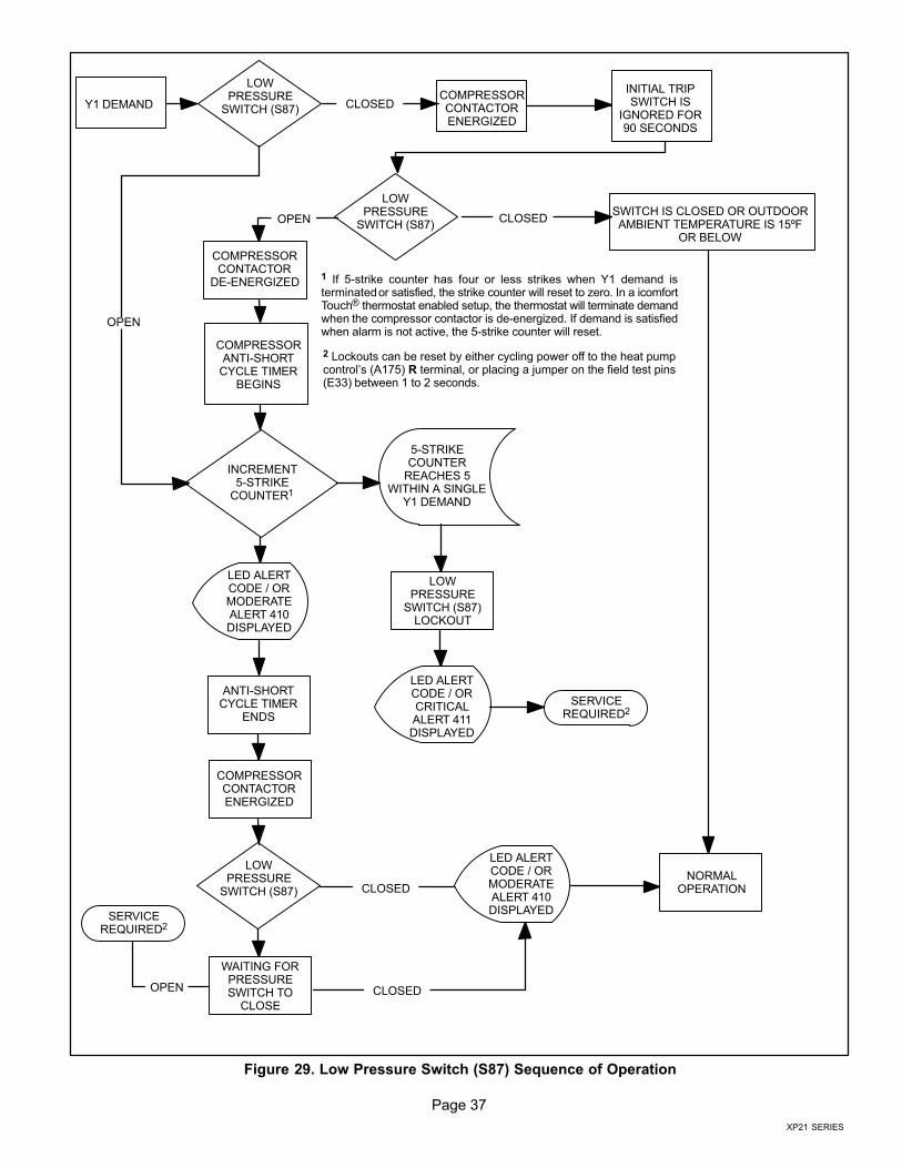
Page 37
XP21 SERIES
Y1 DEMAND
LOWPRESSURE
SWITCH (S87)
COMPRESSORCONTACTORENERGIZED
INITIAL TRIPSWITCH IS
IGNORED FOR90 SECONDS
LOWPRESSURE
SWITCH (S87)
COMPRESSORCONTACTOR
DE−ENERGIZED
COMPRESSORANTI−SHORT
CYCLE TIMERBEGINS
INCREMENT5−STRIKE
COUNTER1
LED ALERTCODE / ORMODERATEALERT 410DISPLAYED
ANTI−SHORTCYCLE TIMER
ENDS
COMPRESSORCONTACTORENERGIZED
LOWPRESSURE
SWITCH (S87)
WAITING FORPRESSURESWITCH TO
CLOSE
SWITCH IS CLOSED OR OUTDOORAMBIENT TEMPERATURE IS 15ºF
OR BELOW
5−STRIKECOUNTER
REACHES 5WITHIN A SINGLE
Y1 DEMAND
LOWPRESSURE
SWITCH (S87)LOCKOUT
LED ALERTCODE / ORCRITICALALERT 411DISPLAYED
SERVICEREQUIRED2
LED ALERTCODE / ORMODERATEALERT 410DISPLAYED
SERVICEREQUIRED2
NORMALOPERATION
CLOSED
CLOSEDOPEN
OPEN
1 If 5−strike counter has four or less strikes when Y1 demand isterminated or satisfied, the strike counter will reset to zero. In a icomfortTouch® thermostat enabled setup, the thermostat will terminate demandwhen the compressor contactor is de−energized. If demand is satisfiedwhen alarm is not active, the 5−strike counter will reset.
2 Lockouts can be reset by either cycling power off to the heat pumpcontrol’s (A175) R terminal, or placing a jumper on the field test pins(E33) between 1 to 2 seconds.
OPEN CLOSED
CLOSED
Figure 29. Low Pressure Switch (S87) Sequence of Operation
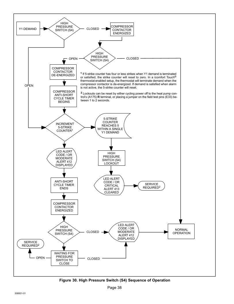
Page 38
506601−01
Y1 DEMAND
HIGHPRESSURE
SWITCH (S4)COMPRESSORCONTACTORENERGIZED
HIGHPRESSURE
SWITCH (S4)
COMPRESSORCONTACTOR
DE−ENERGIZED
COMPRESSORANTI−SHORT
CYCLE TIMERBEGINS
INCREMENT5−STRIKE
COUNTER1
LED ALERTCODE / ORMODERATEALERT 412DISPLAYED
ANTI−SHORTCYCLE TIMER
ENDS
COMPRESSORCONTACTORENERGIZED
HIGHPRESSURE
SWITCH (S4)
WAITING FORPRESSURESWITCH TO
CLOSE
5−STRIKECOUNTER
REACHES 5WITHIN A SINGLE
Y1 DEMAND
HIGHPRESSURE
SWITCH (S4)LOCKOUT
LED ALERTCODE / ORCRITICALALERT 413CLEARED
SERVICEREQUIRED2
LED ALERTCODE / ORMODERATEALERT 412DISPLAYED
SERVICEREQUIRED2
NORMALOPERATION
CLOSED
CLOSEDOPEN
OPEN
1 If 5−strike counter has four or less strikes when Y1 demand is terminatedor satisfied, the strike counter will reset to zero. In a icomfort Touch®
thermostat enabled setup, the thermostat will terminate demand when thecompressor contactor is de−energized. If demand is satisfied when alarmis not active, the 5−strike counter will reset.
2 Lockouts can be reset by either cycling power off to the heat pump con-trol’s (A175) R terminal, or placing a jumper on the field test pins (E33) be-tween 1 to 2 seconds.
OPEN CLOSED
CLOSED
Figure 30. High Pressure Switch (S4) Sequence of Operation
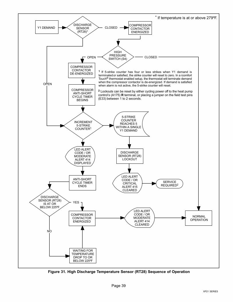
Page 39
XP21 SERIES
Y1 DEMANDDISCHARGE
SENSOR(RT28)*
COMPRESSORCONTACTORENERGIZED
HIGHPRESSURE
SWITCH (S4)
COMPRESSORCONTACTOR
DE−ENERGIZED
COMPRESSORANTI−SHORT
CYCLE TIMERBEGINS
INCREMENT5−STRIKE
COUNTER1
LED ALERTCODE / ORMODERATEALERT 414DISPLAYED
ANTI−SHORTCYCLE TIMER
ENDS
COMPRESSORCONTACTORENERGIZED
DISCHARGESENSOR (RT28)
IS AT ORBELOW 225ºF
WAITING FORTEMPERATURE
DROP TO ORBELOW 225ºF
5−STRIKECOUNTER
REACHES 5WITHIN A SINGLE
Y1 DEMAND
DISCHARGESENSOR (RT28)
LOCKOUT
LED ALERTCODE / ORCRITICALALERT 415CLEARED
SERVICEREQUIRED2
LED ALERTCODE / ORMODERATEALERT 414CLEARED
NORMALOPERATION
CLOSED
CLOSEDOPEN
OPEN
1 If 5−strike counter has four or less strikes when Y1 demand isterminated or satisfied, the strike counter will reset to zero. In a icomfortTouch® thermostat enabled setup, the thermostat will terminate demandwhen the compressor contactor is de−energized. If demand is satisfiedwhen alarm is not active, the 5−strike counter will reset.
2 Lockouts can be reset by either cycling power off to the heat pumpcontrol’s (A175) R terminal, or placing a jumper on the field test pins(E33) between 1 to 2 seconds.
NO
* If temperature is at or above 279ºF.
YES
Figure 31. High Discharge Temperature Sensor (RT28) Sequence of Operation
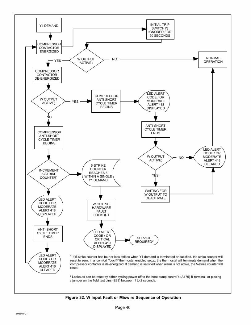
Page 40
506601−01
Y1 DEMAND
COMPRESSORCONTACTORENERGIZED
INITIAL TRIPSWITCH IS
IGNORED FOR90 SECONDS
W OUTPUTACTIVE)
COMPRESSORCONTACTOR
DE−ENERGIZED
COMPRESSORANTI−SHORT
CYCLE TIMERBEGINS
INCREMENT5−STRIKE
COUNTER1
LED ALERTCODE / ORMODERATEALERT 418DISPLAYED
ANTI−SHORTCYCLE TIMER
ENDS
W OUTPUTHARDWARE
FAULTLOCKOUT
WAITING FORW OUTPUT TODEACTIVATE
5−STRIKECOUNTER
REACHES 5WITHIN A SINGLE
Y1 DEMAND
LED ALERTCODE / ORMODERATEALERT 418DISPLAYED
LED ALERTCODE / ORCRITICALALERT 419DISPLAYED
SERVICEREQUIRED2
YES
W OUTPUTACTIVE)
NO
COMPRESSORANTI−SHORT
CYCLE TIMERBEGINS
YES
LED ALERTCODE / ORMODERATEALERT 418CLEARED
ANTI−SHORTCYCLE TIMER
ENDS
W OUTPUTACTIVE)
NORMALOPERATION
LED ALERTCODE / ORMODERATEALERT 418CLEARED
NO
YES
NO
1 If 5−strike counter has four or less strikes when Y1 demand is terminated or satisfied, the strike counter willreset to zero. In a icomfort Touch® thermostat enabled setup, the thermostat will terminate demand when thecompressor contactor is de−energized. If demand is satisfied when alarm is not active, the 5−strike counter willreset.
2 Lockouts can be reset by either cycling power off to the heat pump control’s (A175) R terminal, or placinga jumper on the field test pins (E33) between 1 to 2 seconds.
Figure 32. W Input Fault or Miswire Sequence of Operation
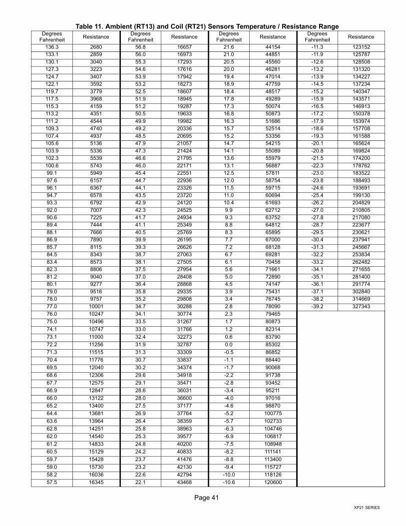
Page 41
XP21 SERIES
Table 11. Ambient (RT13) and Coil (RT21) Sensors Temperature / Resistance RangeDegrees
FahrenheitResistance
DegreesFahrenheit
ResistanceDegrees
FahrenheitResistance
DegreesFahrenheit
Resistance
136.3 2680 56.8 16657 21.6 44154 −11.3 123152
133.1 2859 56.0 16973 21.0 44851 −11.9 125787
130.1 3040 55.3 17293 20.5 45560 −12.6 128508
127.3 3223 54.6 17616 20.0 46281 −13.2 131320
124.7 3407 53.9 17942 19.4 47014 −13.9 134227
122.1 3592 53.2 18273 18.9 47759 −14.5 137234
119.7 3779 52.5 18607 18.4 48517 −15.2 140347
117.5 3968 51.9 18945 17.8 49289 −15.9 143571
115.3 4159 51.2 19287 17.3 50074 −16.5 146913
113.2 4351 50.5 19633 16.8 50873 −17.2 150378
111.2 4544 49.9 19982 16.3 51686 −17.9 153974
109.3 4740 49.2 20336 15.7 52514 −18.6 157708
107.4 4937 48.5 20695 15.2 53356 −19.3 161588
105.6 5136 47.9 21057 14.7 54215 −20.1 165624
103.9 5336 47.3 21424 14.1 55089 −20.8 169824
102.3 5539 46.6 21795 13.6 55979 −21.5 174200
100.6 5743 46.0 22171 13.1 56887 −22.3 178762
99.1 5949 45.4 22551 12.5 57811 −23.0 183522
97.6 6157 44.7 22936 12.0 58754 −23.8 188493
96.1 6367 44.1 23326 11.5 59715 −24.6 193691
94.7 6578 43.5 23720 11.0 60694 −25.4 199130
93.3 6792 42.9 24120 10.4 61693 −26.2 204829
92.0 7007 42.3 24525 9.9 62712 −27.0 210805
90.6 7225 41.7 24934 9.3 63752 −27.8 217080
89.4 7444 41.1 25349 8.8 64812 −28.7 223677
88.1 7666 40.5 25769 8.3 65895 −29.5 230621
86.9 7890 39.9 26195 7.7 67000 −30.4 237941
85.7 8115 39.3 26626 7.2 68128 −31.3 245667
84.5 8343 38.7 27063 6.7 69281 −32.2 253834
83.4 8573 38.1 27505 6.1 70458 −33.2 262482
82.3 8806 37.5 27954 5.6 71661 −34.1 271655
81.2 9040 37.0 28408 5.0 72890 −35.1 281400
80.1 9277 36.4 28868 4.5 74147 −36.1 291774
79.0 9516 35.8 29335 3.9 75431 −37.1 302840
78.0 9757 35.2 29808 3.4 76745 −38.2 314669
77.0 10001 34.7 30288 2.8 78090 −39.2 327343
76.0 10247 34.1 30774 2.3 79465
75.0 10496 33.5 31267 1.7 80873
74.1 10747 33.0 31766 1.2 82314
73.1 11000 32.4 32273 0.6 83790
72.2 11256 31.9 32787 0.0 85302
71.3 11515 31.3 33309 −0.5 86852
70.4 11776 30.7 33837 −1.1 88440
69.5 12040 30.2 34374 −1.7 90068
68.6 12306 29.6 34918 −2.2 91738
67.7 12575 29.1 35471 −2.8 93452
66.9 12847 28.6 36031 −3.4 95211
66.0 13122 28.0 36600 −4.0 97016
65.2 13400 27.5 37177 −4.6 98870
64.4 13681 26.9 37764 −5.2 100775
63.6 13964 26.4 38359 −5.7 102733
62.8 14251 25.8 38963 −6.3 104746
62.0 14540 25.3 39577 −6.9 106817
61.2 14833 24.8 40200 −7.5 108948
60.5 15129 24.2 40833 −8.2 111141
59.7 15428 23.7 41476 −8.8 113400
59.0 15730 23.2 42130 −9.4 115727
58.2 16036 22.6 42794 −10.0 118126
57.5 16345 22.1 43468 −10.6 120600
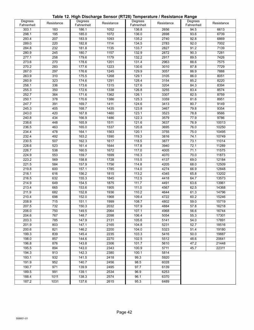
Page 42
506601−01
Table 12. High Discharge Sensor (RT28) Temperature / Resistance RangeDegrees
FahrenheitResistance
DegreesFahrenheit
ResistanceDegrees
FahrenheitResistance
DegreesFahrenheit
Resistance
303.1 183 186.1 1052 136.8 2656 94.5 6613
298.1 195 185.0 1072 136.0 2698 93.6 6739
293.4 207 183.9 1093 135.2 2740 92.8 6869
289.0 220 182.8 1114 134.5 2783 92.0 7002
284.8 232 181.8 1135 133.7 2827 91.2 7139
280.9 245 180.7 1157 132.9 2872 90.3 7281
277.1 258 179.6 1179 132.2 2917 89.5 7426
273.6 270 178.6 1201 131.4 2963 88.6 7575
270.2 283 177.6 1223 130.6 3010 87.8 7729
267.0 297 176.6 1245 129.9 3057 86.9 7888
263.9 310 175.5 1268 129.1 3105 86.0 8051
260.9 323 174.6 1291 128.4 3154 85.2 8220
258.1 336 173.6 1315 127.6 3204 84.3 8394
255.3 350 172.6 1338 126.8 3255 83.4 8574
252.7 364 171.6 1362 126.1 3307 82.5 8759
250.1 378 170.6 1386 125.3 3359 81.6 8951
247.7 391 169.7 1411 124.6 3413 80.7 9149
245.3 405 168.7 1435 123.8 3467 79.8 9354
243.0 420 167.8 1460 123.1 3523 78.8 9566
240.8 434 166.9 1486 122.3 3579 77.9 9786
238.6 448 165.9 1511 121.6 3637 76.9 10013
236.5 463 165.0 1537 120.8 3695 76.0 10250
234.4 478 164.1 1563 120.1 3755 75.0 10495
232.4 492 163.2 1590 119.3 3816 74.1 10749
230.5 507 162.3 1617 118.5 3877 73.1 11014
228.6 523 161.4 1644 117.8 3940 72.1 11289
226.7 538 160.5 1672 117.0 4005 71.1 11575
224.9 553 159.7 1699 116.3 4070 70.0 11873
223.2 569 158.8 1728 115.5 4137 69.0 12184
221.5 584 157.9 1756 114.8 4205 68.0 12509
219.8 600 157.1 1785 114.0 4274 66.9 12848
218.1 616 156.2 1815 113.2 4345 65.8 13202
216.5 632 155.3 1845 112.5 4418 64.7 13573
214.9 649 154.5 1875 111.7 4491 63.6 13961
213.4 665 153.6 1905 111.0 4567 62.5 14368
211.9 682 152.8 1936 110.2 4644 61.3 14796
210.4 698 152.0 1968 109.4 4722 60.2 15246
208.9 715 151.1 1999 108.7 4802 59.0 15719
207.5 732 150.3 2032 107.9 4884 57.8 16218
206.0 750 149.5 2064 107.1 4968 56.6 16744
204.6 767 148.7 2098 106.4 5054 55.3 17301
203.3 785 147.9 2131 105.6 5141 54.0 17891
201.9 803 147.1 2165 104.8 5231 52.7 18516
200.6 821 146.2 2200 104.0 5323 51.4 19180
199.3 839 145.4 2235 103.3 5416 50.0 19887
198.0 857 144.6 2270 102.5 5512 48.6 20641
196.8 876 143.8 2306 101.7 5610 47.2 21448
195.5 894 143.0 2343 100.9 5711 45.7 22311
194.3 913 142.3 2380 100.1 5814
193.1 932 141.5 2418 99.3 5920
191.9 952 140.7 2456 98.5 6028
190.7 971 139.9 2495 97.7 6139
189.5 991 139.1 2534 96.9 6253
188.4 1011 138.3 2574 96.1 6370
187.2 1031 137.6 2615 95.3 6489
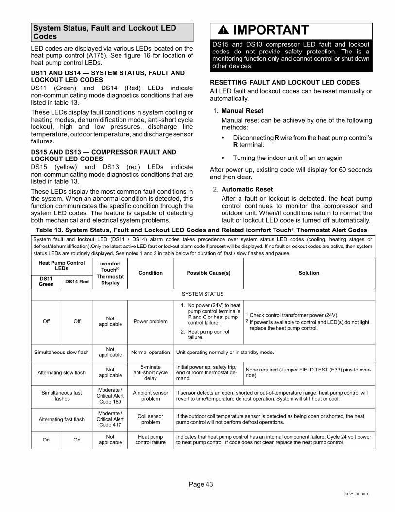
Page 43
XP21 SERIES
System Status, Fault and Lockout LEDCodes
LED codes are displayed via various LEDs located on theheat pump control (A175). See figure 16 for location ofheat pump control LEDs.
DS11 AND DS14 � SYSTEM STATUS, FAULT ANDLOCKOUT LED CODES
DS11 (Green) and DS14 (Red) LEDs indicatenon−communicating mode diagnostics conditions that arelisted in table 13.
These LEDs display fault conditions in system cooling orheating modes, dehumidification mode, anti−short cyclelockout, high and low pressures, discharge linetemperature, outdoor temperature, and discharge sensorfailures.
DS15 AND DS13 � COMPRESSOR FAULT ANDLOCKOUT LED CODES
DS15 (yellow) and DS13 (red) LEDs indicatenon−communicating mode diagnostics conditions that arelisted in table 13.
These LEDs display the most common fault conditions inthe system. When an abnormal condition is detected, thisfunction communicates the specific condition through thesystem LED codes. The feature is capable of detectingboth mechanical and electrical system problems.
IMPORTANTDS15 and DS13 compressor LED fault and lockoutcodes do not provide safety protection. The is amonitoring function only and cannot control or shut downother devices.
RESETTING FAULT AND LOCKOUT LED CODES
All LED fault and lockout codes can be reset manually orautomatically.
1. Manual Reset
Manual reset can be achieve by one of the followingmethods:
� Disconnecting R wire from the heat pump control’sR terminal.
� Turning the indoor unit off an on again
After power up, existing code will display for 60 secondsand then clear.
2. Automatic Reset
After a fault or lockout is detected, the heat pumpcontrol continues to monitor the compressor andoutdoor unit. When/if conditions return to normal, thefault or lockout LED code is turned off automatically.
Table 13. System Status, Fault and Lockout LED Codes and Related icomfort Touch® Thermostat Alert Codes
System fault and lockout LED (DS11 / DS14) alarm codes takes precedence over system status LED codes (cooling, heating stages or
defrost/dehumidification). Only the latest active LED fault or lockout alarm code if present will be displayed. If no fault or lockout codes are active, then system
status LEDs are routinely displayed. See notes 1 and 2 in table below for duration of fast / slow flashes and pause.
Heat Pump ControlLEDs
icomfort
Touch®
Thermostat
Display
Condition Possible Cause(s) SolutionDS11Green
DS14 Red
SYSTEM STATUS
Off OffNot
applicablePower problem
1. No power (24V) to heatpump control terminal’sR and C or heat pumpcontrol failure.
2. Heat pump controlfailure.
1 Check control transformer power (24V).2 If power is available to control and LED(s) do not light,
replace the heat pump control.
Simultaneous slow flashNot
applicableNormal operation Unit operating normally or in standby mode.
Alternating slow flashNot
applicable
5−minuteanti−short cycle
delay
Initial power up, safety trip,end of room thermostat de-mand.
None required (Jumper FIELD TEST (E33) pins to over-ride)
Simultaneous fastflashes
Moderate /Critical AlertCode 180
Ambient sensorproblem
If sensor detects an open, shorted or out−of−temperature range. heat pump control willrevert to time/temperature defrost operation. System will still heat or cool.
Alternating fast flashModerate /
Critical AlertCode 417
Coil sensorproblem
If the outdoor coil temperature sensor is detected as being open or shorted, the heatpump control will not perform defrost operations.
On OnNot
applicableHeat pump
control failureIndicates that heat pump control has an internal component failure. Cycle 24 volt powerto heat pump control. If code does not clear, replace the heat pump control.
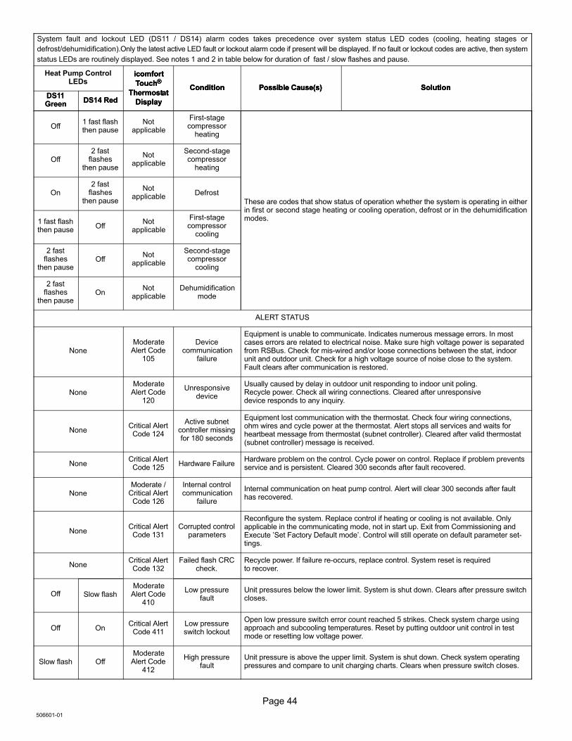
Page 44
506601−01
System fault and lockout LED (DS11 / DS14) alarm codes takes precedence over system status LED codes (cooling, heating stages or
defrost/dehumidification). Only the latest active LED fault or lockout alarm code if present will be displayed. If no fault or lockout codes are active, then system
status LEDs are routinely displayed. See notes 1 and 2 in table below for duration of fast / slow flashes and pause.
Heat Pump ControlLEDs
SolutionPossible Cause(s)Condition
icomfort
Touch®
Thermostat
DisplayDS11Green
SolutionPossible Cause(s)Condition
icomfort
Touch®
Thermostat
DisplayDS14 RedDS11Green
SolutionPossible Cause(s)Condition
icomfort
Touch®
Thermostat
DisplayDS14 Red
Off1 fast flashthen pause
Notapplicable
First−stagecompressor
heating
These are codes that show status of operation whether the system is operating in eitherin first or second stage heating or cooling operation, defrost or in the dehumidificationmodes.
Off2 fast
flashesthen pause
Notapplicable
Second−stagecompressor
heating
On2 fast
flashesthen pause
Notapplicable
Defrost
1 fast flashthen pause
OffNot
applicable
First−stagecompressor
cooling
2 fastflashes
then pauseOff
Notapplicable
Second−stagecompressor
cooling
2 fastflashes
then pauseOn
Notapplicable
Dehumidificationmode
ALERT STATUS
NoneModerateAlert Code
105
Devicecommunication
failure
Equipment is unable to communicate. Indicates numerous message errors. In mostcases errors are related to electrical noise. Make sure high voltage power is separatedfrom RSBus. Check for mis−wired and/or loose connections between the stat, indoorunit and outdoor unit. Check for a high voltage source of noise close to the system.Fault clears after communication is restored.
NoneModerateAlert Code
120
Unresponsivedevice
Usually caused by delay in outdoor unit responding to indoor unit poling.Recycle power. Check all wiring connections. Cleared after unresponsivedevice responds to any inquiry.
NoneCritical AlertCode 124
Active subnetcontroller missingfor 180 seconds
Equipment lost communication with the thermostat. Check four wiring connections,ohm wires and cycle power at the thermostat. Alert stops all services and waits forheartbeat message from thermostat (subnet controller). Cleared after valid thermostat(subnet controller) message is received.
NoneCritical AlertCode 125
Hardware FailureHardware problem on the control. Cycle power on control. Replace if problem preventsservice and is persistent. Cleared 300 seconds after fault recovered.
NoneModerate /
Critical AlertCode 126
Internal controlcommunication
failure
Internal communication on heat pump control. Alert will clear 300 seconds after faulthas recovered.
NoneCritical AlertCode 131
Corrupted controlparameters
Reconfigure the system. Replace control if heating or cooling is not available. Onlyapplicable in the communicating mode, not in start up. Exit from Commissioning andExecute ´Set Factory Default mode´. Control will still operate on default parameter set-tings.
NoneCritical AlertCode 132
Failed flash CRCcheck.
Recycle power. If failure re−occurs, replace control. System reset is requiredto recover.
Off Slow flashModerateAlert Code
410
Low pressurefault
Unit pressures below the lower limit. System is shut down. Clears after pressure switchcloses.
Off OnCritical Alert
Code 411Low pressureswitch lockout
Open low pressure switch error count reached 5 strikes. Check system charge usingapproach and subcooling temperatures. Reset by putting outdoor unit control in testmode or resetting low voltage power.
Slow flash OffModerateAlert Code
412
High pressurefault
Unit pressure is above the upper limit. System is shut down. Check system operatingpressures and compare to unit charging charts. Clears when pressure switch closes.
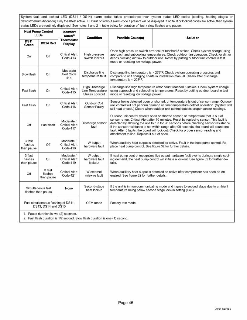
Page 45
XP21 SERIES
System fault and lockout LED (DS11 / DS14) alarm codes takes precedence over system status LED codes (cooling, heating stages or
defrost/dehumidification). Only the latest active LED fault or lockout alarm code if present will be displayed. If no fault or lockout codes are active, then system
status LEDs are routinely displayed. See notes 1 and 2 in table below for duration of fast / slow flashes and pause.
Heat Pump ControlLEDs
SolutionPossible Cause(s)Condition
icomfort
Touch®
Thermostat
DisplayDS11Green
SolutionPossible Cause(s)Condition
icomfort
Touch®
Thermostat
DisplayDS14 RedDS11Green
SolutionPossible Cause(s)Condition
icomfort
Touch®
Thermostat
DisplayDS14 Red
On OffCritical AlertCode 413
High pressureswitch lockout
Open high pressure switch error count reached 5 strikes. Check system charge usingapproach and subcooling temperatures. Check outdoor fan operation. Check for dirt ordebris blocking air flow to outdoor unit. Reset by putting outdoor unit control in testmode or resetting low voltage power.
Slow flash OnModerateAlert Code
414
Discharge linetemperature fault
Discharge line temperature is > 279ºF. Check system operating pressures andcompare to unit charging charts in installation manual. Clears after dischargetemperature is < 225ºF.
Fast flash OnCritical AlertCode 415
High DischargeLine TemperatureStrikes Lockout
Discharge line high temperature error count reached 5 strikes. Check system chargeusing approach and subcooling temperatures. Reset by putting outdoor board in testmode or resetting low voltage power.
Fast flash OnCritical AlertCode 416
Outdoor CoilSensor Faulty
Sensor being detected open or shorted, or temperature is out of sensor range. Outdoorunit control will not perform demand or time/temperature defrost operation. (System willstill heat or cool.) Clears when outdoor unit control detects proper sensor readings.
Off Fast flashModerate /
Critical AlertCode 417
Discharge sensorfault
Outdoor unit control detects open or shorted sensor, or temperature that is out ofsensor range. Critical Alert after 10 minutes. Reset by replacing sensor. This fault isdetected by allowing the unit to run for 90 seconds before checking sensor resistance.If the sensor resistance is not within range after 90 seconds, the board will count onefault. After 5 faults, the board will lock out. Check for proper sensor reading andattachment to line. Replace if out−of−spec.
3 fastflashes
then pauseOff
Moderate /Critical AlertCode 418
W outputhardware fault
When auxiliary heat output is detected as active. Fault in the heat pump control. Re-place heat pump control. See figure 32 for further details.
3 fastflashes
then pauseOn
Moderate /Critical AlertCode 419
W outputhardware fault
lockout
If heat pump control recognizes five output hardware fault events during a single cool-ing demand, the heat pump control will initiate a lockout. See figure 32 for further de-tails.
Off3 fast
flashesthen pause
Critical AlertCode 421
W externalmiswire fault
When auxiliary heat output is detected as active after compressor has been de−en-ergized. See figure 32 for further details.
Simultaneous fastflashes then pause
NoneSecond−stageheat lock−in
If the unit is in non−communicating mode and it goes to second stage due to ambienttemperature being below second stage lock−in setting (E48).
Fast simultaneous flashing of DS11,DS13, DS14 and DS15
OEM mode Factory test mode.
1. Pause duration is two (2) seconds.
2. Fast flash duration is 1/2 second. Slow flash duration is one (1) second.
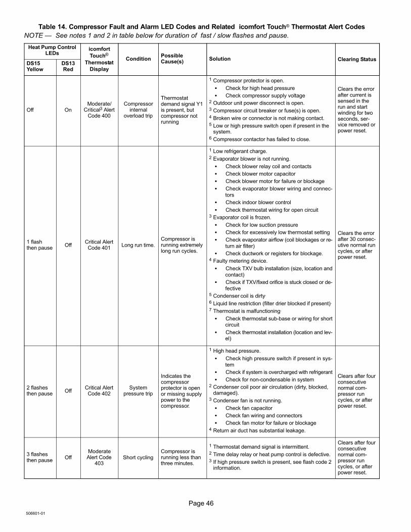
Page 46
506601−01
Table 14. Compressor Fault and Alarm LED Codes and Related icomfort Touch® Thermostat Alert Codes
NOTE � See notes 1 and 2 in table below for duration of fast / slow flashes and pause.
Heat Pump ControlLEDs
icomfort
Touch®
Thermostat
Display
ConditionPossibleCause(s)
Solution Clearing StatusDS15Yellow
DS13Red
Off OnModerate/
Critical3 AlertCode 400
Compressorinternal
overload trip
Thermostatdemand signal Y1is present, butcompressor notrunning
1 Compressor protector is open.
� Check for high head pressure
� Check compressor supply voltage2 Outdoor unit power disconnect is open.3 Compressor circuit breaker or fuse(s) is open.4 Broken wire or connector is not making contact.5 Low or high pressure switch open if present in the
system.6 Compressor contactor has failed to close.
Clears the errorafter current issensed in therun and startwinding for twoseconds, ser-vice removed orpower reset.
1 flashthen pause
OffCritical AlertCode 401
Long run time.Compressor isrunning extremelylong run cycles.
1 Low refrigerant charge.2 Evaporator blower is not running.
� Check blower relay coil and contacts
� Check blower motor capacitor
� Check blower motor for failure or blockage
� Check evaporator blower wiring and connec-tors
� Check indoor blower control
� Check thermostat wiring for open circuit3 Evaporator coil is frozen.
� Check for low suction pressure
� Check for excessively low thermostat setting
� Check evaporator airflow (coil blockages or re-turn air filter)
� Check ductwork or registers for blockage.4 Faulty metering device.
� Check TXV bulb installation (size, location andcontact)
� Check if TXV/fixed orifice is stuck closed or de-fective
5 Condenser coil is dirty.
6 Liquid line restriction (filter drier blocked if present).
7 Thermostat is malfunctioning.
� Check thermostat sub−base or wiring for shortcircuit
� Check thermostat installation (location and lev-el)
Clears the errorafter 30 consec-utive normal runcycles, or afterpower reset.
2 flashesthen pause
OffCritical AlertCode 402
Systempressure trip
Indicates thecompressorprotector is openor missing supplypower to thecompressor.
1 High head pressure.
� Check high pressure switch if present in sys-tem
� Check if system is overcharged with refrigerant
� Check for non−condensable in system2 Condenser coil poor air circulation (dirty, blocked,
damaged).3 Condenser fan is not running.
� Check fan capacitor
� Check fan wiring and connectors
� Check fan motor for failure or blockage4 Return air duct has substantial leakage.
Clears after fourconsecutivenormal com-pressor runcycles, or afterpower reset.
3 flashesthen pause
OffModerateAlert Code
403Short cycling
Compressor isrunning less thanthree minutes.
1 Thermostat demand signal is intermittent.2 Time delay relay or heat pump control is defective.3 If high pressure switch is present, see flash code 2
information.
Clears after fourconsecutivenormal com-pressor runcycles, or afterpower reset.
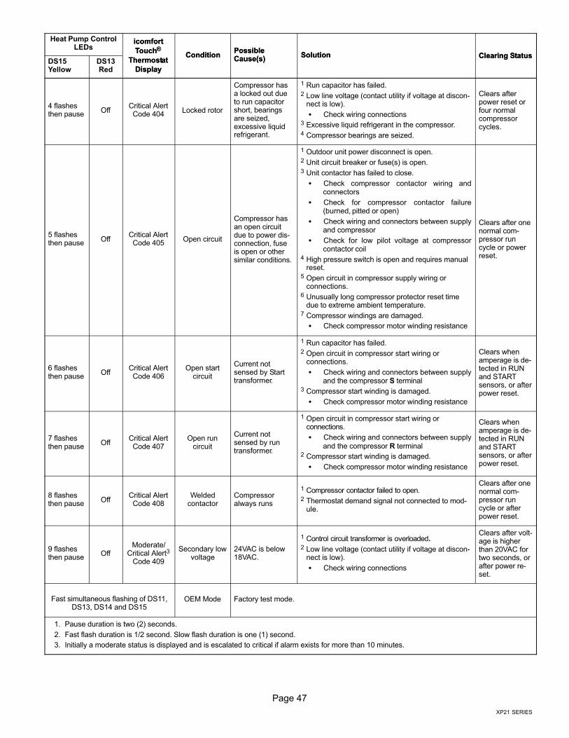
Page 47
XP21 SERIES
Heat Pump ControlLEDs
Clearing StatusSolutionPossibleCause(s)
Condition
icomfort
Touch®
Thermostat
DisplayDS15Yellow
Clearing StatusSolutionPossibleCause(s)
Condition
icomfort
Touch®
Thermostat
DisplayDS13Red
4 flashesthen pause
OffCritical AlertCode 404
Locked rotor
Compressor hasa locked out dueto run capacitorshort, bearingsare seized,excessive liquidrefrigerant.
1 Run capacitor has failed.2 Low line voltage (contact utility if voltage at discon-
nect is low).
� Check wiring connections3 Excessive liquid refrigerant in the compressor.4 Compressor bearings are seized.
Clears afterpower reset orfour normalcompressorcycles.
5 flashesthen pause
OffCritical AlertCode 405
Open circuit
Compressor hasan open circuitdue to power dis-connection, fuseis open or othersimilar conditions.
1 Outdoor unit power disconnect is open.2 Unit circuit breaker or fuse(s) is open.3 Unit contactor has failed to close.
� Check compressor contactor wiring andconnectors
� Check for compressor contactor failure(burned, pitted or open)
� Check wiring and connectors between supplyand compressor
� Check for low pilot voltage at compressorcontactor coil
4 High pressure switch is open and requires manualreset.
5 Open circuit in compressor supply wiring orconnections.
6 Unusually long compressor protector reset timedue to extreme ambient temperature.
7 Compressor windings are damaged.
� Check compressor motor winding resistance
Clears after onenormal com-pressor runcycle or powerreset.
6 flashesthen pause
OffCritical AlertCode 406
Open startcircuit
Current notsensed by Starttransformer.
1 Run capacitor has failed.2 Open circuit in compressor start wiring or
connections.
� Check wiring and connectors between supplyand the compressor S terminal
3 Compressor start winding is damaged.
� Check compressor motor winding resistance
Clears whenamperage is de-tected in RUNand STARTsensors, or afterpower reset.
7 flashesthen pause
OffCritical AlertCode 407
Open runcircuit
Current notsensed by runtransformer.
1 Open circuit in compressor start wiring orconnections.
� Check wiring and connectors between supplyand the compressor R terminal
2 Compressor start winding is damaged.
� Check compressor motor winding resistance
Clears whenamperage is de-tected in RUNand STARTsensors, or afterpower reset.
8 flashesthen pause
OffCritical AlertCode 408
Weldedcontactor
Compressoralways runs
1 Compressor contactor failed to open.2 Thermostat demand signal not connected to mod-
ule.
Clears after onenormal com-pressor runcycle or afterpower reset.
9 flashesthen pause
OffModerate/
Critical Alert3
Code 409
Secondary lowvoltage
24VAC is below18VAC.
1 Control circuit transformer is overloaded.2 Low line voltage (contact utility if voltage at discon-
nect is low).
� Check wiring connections
Clears after volt-age is higherthan 20VAC fortwo seconds, orafter power re-set.
Fast simultaneous flashing of DS11,DS13, DS14 and DS15
OEM Mode Factory test mode.
1. Pause duration is two (2) seconds.
2. Fast flash duration is 1/2 second. Slow flash duration is one (1) second.
3. Initially a moderate status is displayed and is escalated to critical if alarm exists for more than 10 minutes.
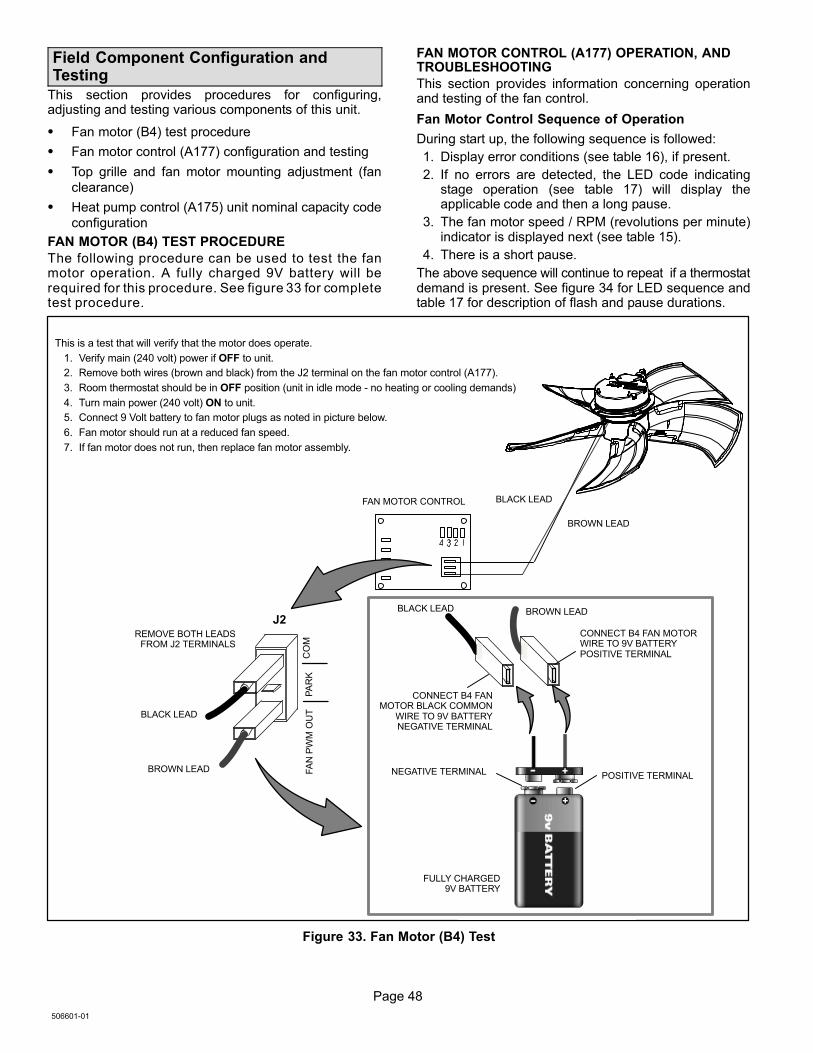
Page 48
506601−01
Field Component Configuration andTesting
This section provides procedures for configuring,adjusting and testing various components of this unit.
� Fan motor (B4) test procedure
� Fan motor control (A177) configuration and testing
� Top grille and fan motor mounting adjustment (fan
clearance)
� Heat pump control (A175) unit nominal capacity code
configuration
FAN MOTOR (B4) TEST PROCEDURE
The following procedure can be used to test the fanmotor operation. A fully charged 9V battery will berequired for this procedure. See figure 33 for completetest procedure.
FAN MOTOR CONTROL (A177) OPERATION, ANDTROUBLESHOOTING
This section provides information concerning operationand testing of the fan control.
Fan Motor Control Sequence of Operation
During start up, the following sequence is followed:
1. Display error conditions (see table 16), if present.
2. If no errors are detected, the LED code indicatingstage operation (see table 17) will display theapplicable code and then a long pause.
3. The fan motor speed / RPM (revolutions per minute)indicator is displayed next (see table 15).
4. There is a short pause.
The above sequence will continue to repeat if a thermostatdemand is present. See figure 34 for LED sequence andtable 17 for description of flash and pause durations.
J2
FA
N P
WM
OU
TP
AR
KC
OM
BLACK LEAD
BROWN LEAD
BROWN LEADBLACK LEAD
REMOVE BOTH LEADSFROM J2 TERMINALS
CONNECT B4 FANMOTOR BLACK COMMON
WIRE TO 9V BATTERYNEGATIVE TERMINAL
FAN MOTOR CONTROL BLACK LEAD
BROWN LEAD
FULLY CHARGED9V BATTERY
This is a test that will verify that the motor does operate.
1. Verify main (240 volt) power if OFF to unit.
2. Remove both wires (brown and black) from the J2 terminal on the fan motor control (A177).
3. Room thermostat should be in OFF position (unit in idle mode − no heating or cooling demands)
4. Turn main power (240 volt) ON to unit.
5. Connect 9 Volt battery to fan motor plugs as noted in picture below.
6. Fan motor should run at a reduced fan speed.
7. If fan motor does not run, then replace fan motor assembly.
NEGATIVE TERMINAL POSITIVE TERMINAL
CONNECT B4 FAN MOTORWIRE TO 9V BATTERYPOSITIVE TERMINAL
V
Figure 33. Fan Motor (B4) Test
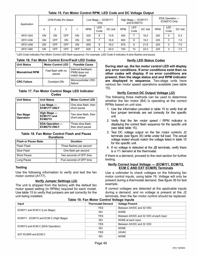
Page 49
XP21 SERIES
Table 15. Fan Motor Control RPM, LED Code and DC Voltage Output
Application
CFM Profile Pin Select Low Stage � ECM1/Y1Only
High Stage � ECM1/Y1and ECM2/Y2
EDA Operation �ECM2/Y2 Only
4 3 2 1 RPMLED
CodeDC Volt RPM
LED
CodeDC Volt RPM
LED
CodeDC Volt
XP21−024 ON ON OFF ON 425 6 13.6 500 7 16.0 200 3 6.3
XP21−036 ON OFF ON ON 525 7 16.8 600 8 19.2 225 3 7.0
XP21−048 ON OFF OFF ON 600 8 19.2 675 9 21.6 225 3 7.0
XP21−060 ON OFF OFF OFF 625 8 20.0 700 10 22.5 225 3 7.0
* LED Code indicates Fan Motor Control LED flash sequence. For example, LED Code 9 indicates 9 slow flashes and pause.
Table 16. Fan Motor Control Error/Fault LED Codes
Unit Status Motor Control LED Possible Cause
Mismatched RPMFast flash with no
pause
Internal feedback,PWM does notmatch target
CRC Failure Constant ON.Microcontroller CRCfailure
Table 17. Fan Motor Control Stage LED IndicatorCodes
Unit Status Unit Status Motor Control LED
Two StageOperation
Low Stage �ECM1/Y1 ONLY
One slow flash, thenshort pause
High Stage �ECM1/Y1 andECM2/Y2
Two slow flash, thenshort pause
EDA Operation �ECM2/Y2 ONLY
Three slow flash,then short pause
Table 18. Fan Motor Control Flash and PauseDurations
Flash or Pause State Duration
Flash Flash Three flashes per second
Slow Flash One flash per second
Short Pause Two seconds of OFF time
Long Pause Five seconds of OFF time
Testing
Use the following information to verify and test the fanmotor control (A177).
Verify Jumper Settings (J2)
The unit is shipped from the factory with the default fanmotor speed setting (in RPMs) required for each model.Use table 15 to verify that jumpers are set correctly for theunit being installed.
Verify LED Status Codes
During start up, the fan motor control LED will displayany error conditions. If error conditions exist then noother codes will display. If no error conditions arepresent, then the stage status and and RPM indicatorare displayed in sequence. Two−stage units havevarious fan motor speed operations available (see table15).
Verify Correct DC Output Voltage (J2)
The following three methods can be used to determinewhether the fan motor (B4) is operating at the correctRPMs based on unit size.
1. Use the information provided in table 15 to verify that allfour jumper terminals are set correctly for the specificunit.
2. Verify that the fan motor speed / RPM indicator isdisplaying the correct flash sequence for the specific unit(see table table 15).
3. Test DC voltage output on the fan motor control’s J2terminals (see figure 35) while under full load. The actualvoltage tested should match the voltage listed in table 15for the specific unit.
4. If no voltage is detected at the J2 terminals, verify thereis a Y1 demand at the thermostat.
If there is a demand, proceed to the next section for furthertesting.
Verify Correct Input Voltage � (ECM/Y1, ECM/Y2,ECM C AND EXT ECM/R) Terminals
Use a voltmeter to check voltages on the following fanmotor control inputs, using table 19. Voltage will only bepresent during a thermostat demand. See figure 36 for testexample.
If correct voltages are detected at the applicable inputs
during a demand, and no voltage is present at the J2terminals, then the fan motor control should be replaced.
Table 19. Fan Motor Control Voltage Inputs
Input Thermostat Demand Voltage Present
ECM/Y1 and ECM C (Low Stage)YES Between 24VDC and 32 VDC
NO NONE
ECM/Y1 − ECM/Y2 and ECM C (High Stage)YES Between 24VDC and 32 VDC at each input
NO NONE at each input
ECM/Y2 and ECM C (EDA Operation)YES Between 24VDC and 32 VDC
NO NONE
EXT ECM/R and ECM CYES 24VAC
NO NONE
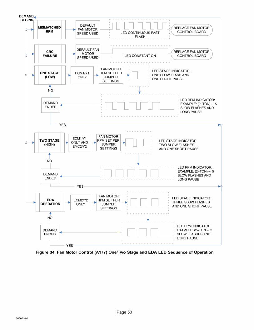
Page 50
506601−01
DEMAND
MISMATCHEDRPM
DEFAULTFAN MOTORSPEED USED LED CONTINUOUS FAST
FLASH
REPLACE FAN MOTORCONTROL BOARD
CRCFAILURE
DEFAULT FANMOTOR
SPEED USED LED CONSTANT ON
ONE STAGE(LOW)
ECM1/Y1ONLY
LED STAGE INDICATOR: ONE SLOW FLASH ANDONE SHORT PAUSE
LED RPM INDICATOR: EXAMPLE: (2−TON) – 5 SLOW FLASHES ANDLONG PAUSE
TWO STAGE(HIGH)
LED STAGE INDICATOR: TWO SLOW FLASHESAND ONE SHORT PAUSE
LED RPM INDICATOR: EXAMPLE: (2−TON) – 5SLOW FLASHES AND LONG PAUSE
EDA OPERATION
ECM2/Y2ONLY
LED STAGE INDICATOR: THREE SLOW FLASHES AND ONE SHORT PAUSE
LED RPM INDICATOR: EXAMPLE: (2−TON – 3SLOW FLASHES AND LONG PAUSE
DEMANDENDED
NO
DEMANDENDED
NO
DEMANDENDED
NO
YES
YES
FAN MOTORRPM SET PER
JUMPERSETTINGS
ECM1/Y1ONLY ANDEMC2/Y2
FAN MOTORRPM SET PER
JUMPER SETTINGS
FAN MOTORRPM SET PER
JUMPERSETTINGS
REPLACE FAN MOTORCONTROL BOARD
BEGINS
YES
Figure 34. Fan Motor Control (A177) One/Two Stage and EDA LED Sequence of Operation
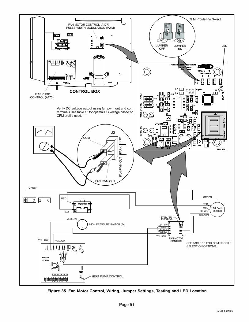
Page 51
XP21 SERIES
HEAT PUMPCONTROL (A175)
CONTROL BOX
FAN MOTOR CONTROL (A177) �PULSE−WIDTH MODULATION (PWM)
JUMPEROFF
JUMPERON
J2
LED
CFM Profile Pin Select
Verify DC voltage output using fan pwm out and comterminals. see table 15 for optimal DC voltage based onCFM profile used.
COM
FAN PWM OUT
FA
N P
WM
OU
TP
AR
KC
OM
J2
GREEN
RED
BROWN
RED
BLACKRED
RED
GREEN
FAN MOTORCONTROL
YELLOW
BLACK
YELLOWBLUE
SEE TABLE 15 FOR CFM PROFILESELECTION OPTIONS.
YELLOW
YELLOW
YELLOW
HIGH PRESSURE SWITCH (S4)
YELLOW
B4 FANMOTOR
HEAT PUMP CONTROL
Figure 35. Fan Motor Control, Wiring, Jumper Settings, Testing and LED Location
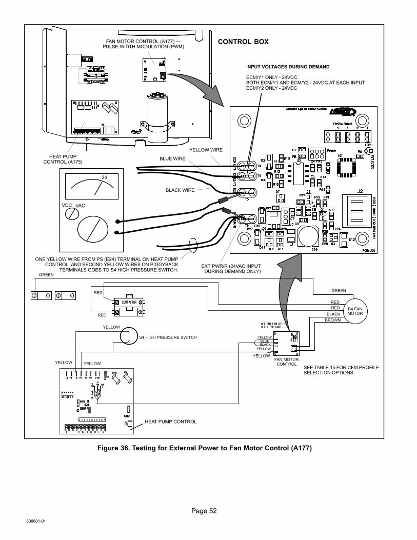
Page 52
506601−01
HEAT PUMPCONTROL (A175)
CONTROL BOXFAN MOTOR CONTROL (A177) �PULSE−WIDTH MODULATION (PWM)
ONE YELLOW WIRE FROM PS (E24) TERMINAL ON HEAT PUMPCONTROL. AND SECOND YELLOW WIRES ON PIGGYBACK
TERMINALS GOES TO S4 HIGH PRESSURE SWITCH.
GREEN
RED
BROWN
RED
BLACKRED
RED
GREEN
FAN MOTORCONTROL
YELLOW
BLACK
YELLOWBLUE
SEE TABLE 15 FOR CFM PROFILESELECTION OPTIONS.
BLACK WIRE
YELLOW WIRE
VACVDC
24
EXT PWR/R (24VAC INPUTDURING DEMAND ONLY)
INPUT VOLTAGES DURING DEMAND
ECM/Y1 ONLY − 24VDCBOTH ECM/Y1 AND ECM/Y2 − 24VDC AT EACH INPUTECM/Y2 ONLY − 24VDC
BLUE WIRE
YELLOW
YELLOW
YELLOW
S4 HIGH PRESSURE SWITCH
YELLOW
HEAT PUMP CONTROL
B4 FANMOTOR
Figure 36. Testing for External Power to Fan Motor Control (A177)
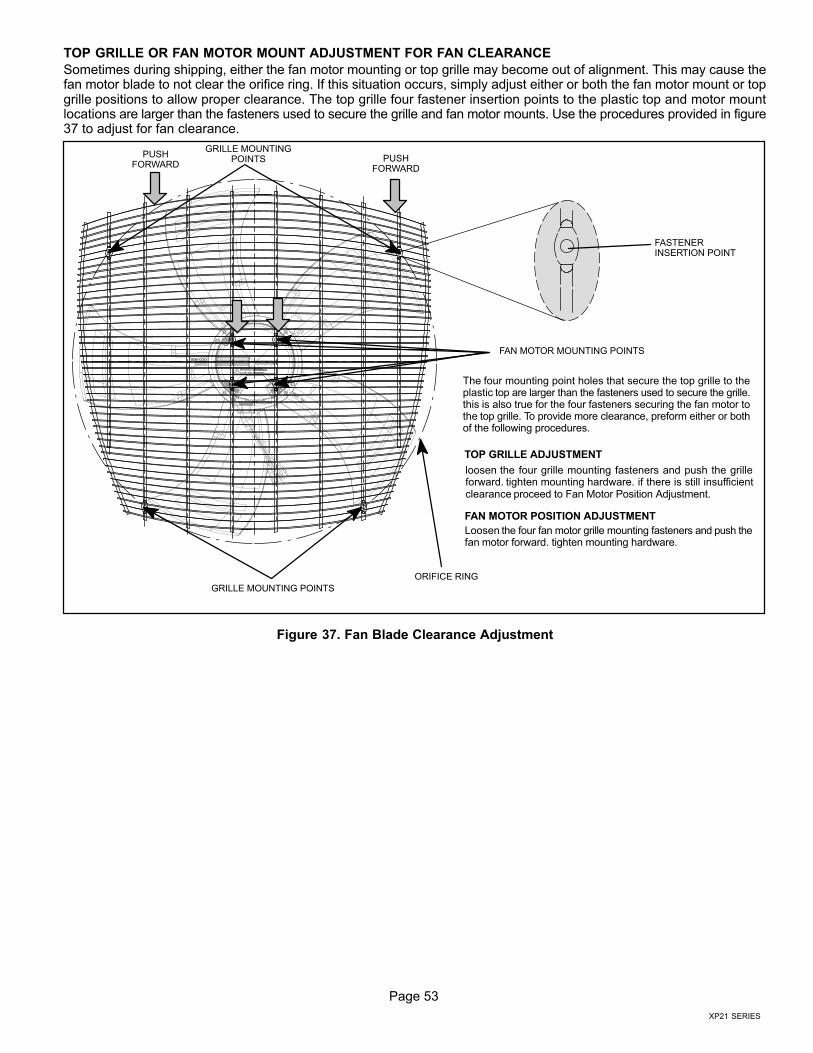
Page 53
XP21 SERIES
TOP GRILLE OR FAN MOTOR MOUNT ADJUSTMENT FOR FAN CLEARANCE
Sometimes during shipping, either the fan motor mounting or top grille may become out of alignment. This may cause thefan motor blade to not clear the orifice ring. If this situation occurs, simply adjust either or both the fan motor mount or topgrille positions to allow proper clearance. The top grille four fastener insertion points to the plastic top and motor mountlocations are larger than the fasteners used to secure the grille and fan motor mounts. Use the procedures provided in figure37 to adjust for fan clearance.
GRILLE MOUNTINGPOINTS
GRILLE MOUNTING POINTS
FASTENERINSERTION POINT
FAN MOTOR MOUNTING POINTS
PUSHFORWARD
PUSHFORWARD
The four mounting point holes that secure the top grille to theplastic top are larger than the fasteners used to secure the grille.this is also true for the four fasteners securing the fan motor tothe top grille. To provide more clearance, preform either or bothof the following procedures.
TOP GRILLE ADJUSTMENT
loosen the four grille mounting fasteners and push the grilleforward. tighten mounting hardware. if there is still insufficientclearance proceed to Fan Motor Position Adjustment.
ORIFICE RING
FAN MOTOR POSITION ADJUSTMENT
Loosen the four fan motor grille mounting fasteners and push thefan motor forward. tighten mounting hardware.
Figure 37. Fan Blade Clearance Adjustment
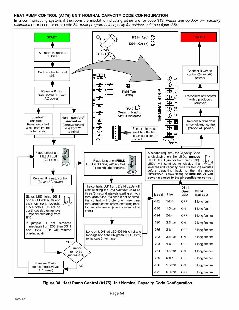
Page 54
506601−01
HEAT PUMP CONTROL (A175) UNIT NOMINAL CAPACITY CODE CONFIGURATION
In a communicating system, if the room thermostat is indicating either a error code 313, indoor and outdoor unit capacitymismatch error code, or error code 34, must program unit capacity for outdoor unit (see figure 38).
When the required Unit Capacity Codeis displaying on the LEDs, removeFIELD TEST jumper from pins (E33).LEDs will continue to display theselected unit capacity code for two (2) minutesbefore defaulting back to the idle mode{simultaneous slow flash}, or until the 24 voltpower is cycled to the air conditioner control.
START
Set room thermostatto OFF
Go to control terminalstrip
Remove R wirefrom control (24 volt
AC power)
icomfort®
enabled �Remove control
wires from i+ andi− terminals
Non − icomfort®
enabled �Remove control
wire from Y1terminal
Place jumper onFIELD TEST
(E33 pins)
Connect R wire to control(24 volt AC power)
DS14 (Red)
DS11 (Green)
TE
RM
INA
L S
TR
IP
Status LED lights DS11and DS14 will blink andthen on continuously.Once both LEDs are oncontinuously then removejumper immediately fromE33.
Place jumper on FIELDTEST (E33 pins) within 2 to 4
seconds after removal
The control´s DS11 and DS14 LEDs willstart blinking the Unit Nominal Code atthree (3) second intervals starting at 1−tonthrough to 6−ton. If a code is not selected,the control will cycle one more timethrough the codes before defaulting backto the idle mode (simultaneous slowflash).
Long blink ON red LED (DS14) to indicatetonnage and solid ON green LED (DS11)to indicate ½ tonnage.
Model
DS11GreenLEDSize
DS14Red LED
−012
−018
−024
−030
−036
−042
−048
−054
−060
−066
−072
1−ton
1.5−ton
2−ton
2.5−ton
3−ton
3.5−ton
4−ton
4.5−ton
5−ton
5.5−ton
6.0−ton
OFF
ON
OFF
ON
OFF
ON
OFF
ON
OFF
ON
OFF
1 long flash
1 long flash
2 long flashes
2 long flashes
3 long flashes
3 long flashes
4 long flashes
4 long flashes
5 long flashes
5 long flashes
6 long flashes
FINISH
Field Test(E33)
DS12CommunicatingStatus Indicator
Sensor harnessmust be attachedto air conditionercontrol.
Remove R wire fromair conditioner control
(24 volt AC power)
Connect R wire tocontrol (24 volt AC
power)
Reconnect any controlwiring previously
removed.
If jumper is not removedimmediately from E33, then DS11and DS14 LEDs will resumeblinking again.
Remove R wirefrom control (24 volt
AC power)
Jumperremoved
successfully
YES
NO
Figure 38. Heat Pump Control (A175) Unit Nominal Capacity Code Configuration
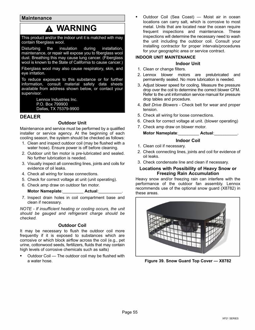
Page 55
XP21 SERIES
Maintenance
WARNINGThis product and/or the indoor unit it is matched with maycontain fiberglass wool.
Disturbing the insulation during installation,maintenance, or repair will expose you to fiberglass wooldust. Breathing this may cause lung cancer. (Fiberglasswool is known to the State of California to cause cancer.)
Fiberglass wool may also cause respiratory, skin, andeye irritation.
To reduce exposure to this substance or for furtherinformation, consult material safety data sheetsavailable from address shown below, or contact yoursupervisor.
Lennox Industries Inc.P.O. Box 799900Dallas, TX 75379−9900
DEALER
Outdoor Unit
Maintenance and service must be performed by a qualifiedinstaller or service agency. At the beginning of eachcooling season, the system should be checked as follows:
1. Clean and inspect outdoor coil (may be flushed with awater hose). Ensure power is off before cleaning.
2. Outdoor unit fan motor is pre−lubricated and sealed.No further lubrication is needed.
3. Visually inspect all connecting lines, joints and coils forevidence of oil leaks.
4. Check all wiring for loose connections.
5. Check for correct voltage at unit (unit operating).
6. Check amp draw on outdoor fan motor.
Motor Nameplate:_________ Actual:__________.
7. Inspect drain holes in coil compartment base andclean if necessary.
NOTE - If insufficient heating or cooling occurs, the unitshould be gauged and refrigerant charge should bechecked.
Outdoor Coil
It may be necessary to flush the outdoor coil morefrequently if it is exposed to substances which arecorrosive or which block airflow across the coil (e.g., peturine, cottonwood seeds, fertilizers, fluids that may containhigh levels of corrosive chemicals such as salts)
� Outdoor Coil � The outdoor coil may be flushed with
a water hose.
� Outdoor Coil (Sea Coast) � Moist air in ocean
locations can carry salt, which is corrosive to most
metal. Units that are located near the ocean requirefrequent inspections and maintenance. These
inspections will determine the necessary need to washthe unit including the outdoor coil. Consult yourinstalling contractor for proper intervals/procedures
for your geographic area or service contract.
INDOOR UNIT MAINTENANCE
Indoor Unit1. Clean or change filters.
2. Lennox blower motors are prelubricated andpermanently sealed. No more lubrication is needed.
3. Adjust blower speed for cooling. Measure the pressuredrop over the coil to determine the correct blower CFM.Refer to the unit information service manual for pressuredrop tables and procedure.
4. Belt Drive Blowers − Check belt for wear and propertension.
5. Check all wiring for loose connections.
6. Check for correct voltage at unit. (blower operating)
7. Check amp draw on blower motor.
Motor Nameplate:_________ Actual:__________.
Indoor Coil1. Clean coil if necessary.
2. Check connecting lines, joints and coil for evidence ofoil leaks.
3. Check condensate line and clean if necessary.
Locations with Possibility of Heavy Snow orFreezing Rain Accumulation
Heavy snow and/or freezing rain can interfere with theperformance of the outdoor fan assembly. Lennoxrecommends use of the optional snow guard (X8782) inthese areas.
Figure 39. Snow Guard Top Cover � X8782
Page 56
506601−01
HOMEOWNERCleaning of the outdoor unit’s coil should be performed bya trained service technician. Contact your dealer and setup a schedule (preferably twice a year, but at least once ayear) to inspect and service your outdoor unit. Thefollowing maintenance may be performed by thehomeowner.
IMPORTANTSprinklers and soaker hoses should not be installedwhere they could cause prolonged exposure to theoutdoor unit by treated water. Prolonged exposure of theunit to treated water (i.e., sprinkler systems, soakers,waste water, etc.) will corrode the surface of steel andaluminum parts and diminish performance and longevityof the unit.
Outdoor Coil
The outdoor unit must be properly maintained to ensure itsproper operation.
� Please contact your dealer to schedule proper
inspection and maintenance for your equipment.
� Make sure no obstructions restrict airflow to the
outdoor unit.
� Grass clippings, leaves, or shrubs crowding the unit
can cause the unit to work harder and use moreenergy.
� Keep shrubbery trimmed away from the unit and
periodically check for debris which collects around theunit.
Routine Maintenance
In order to ensure peak performance, your system must beproperly maintained. Clogged filters and blocked airflowprevent your unit from operating at its most efficient level.
1. Air Filter � Ask your Lennox dealer to show youwhere your indoor unit’s filter is located. It will be eitherat the indoor unit (installed internal or external to thecabinet) or behind a return air grille in the wall orceiling. Check the filter monthly and clean or replaceit as needed.
2. Disposable Filter � Disposable filters should bereplaced with a filter of the same type and size.
NOTE � If you are unsure about the filter required for yoursystem, call your Lennox dealer for assistance.
3. Reusable Filter � Many indoor units are equippedwith reusable foam filters. Clean foam filters with amild soap and water solution; rinse thoroughly; allowfilter to dry completely before returning it to the unit orgrille.
NOTE � The filter and all access panels must be in placeany time the unit is in operation.
4. Lennox Branded Air Filters � are designed toremove airborne particles from the air passing throughthe filter.
5. Indoor Unit � The indoor unit’s evaporator coil isequipped with a drain pan to collect condensateformed as your system removes humidity from the
inside air. Have your dealer show you the location ofthe drain line and how to check for obstructions. (Thiswould also apply to an auxiliary drain, if installed.)
Thermostat OperationSee the ComfortSense® 7000 or icomfort Touch®
thermostat homeowner manual for instructions on how tooperate your thermostat.
Heat Pump OperationYour new Lennox heat pump has several characteristicsthat you should be aware of:
� Heat pumps satisfy heating demand by delivering
large amounts of warm air into the living space. This
is quite different from gas- or oil-fired furnaces or anelectric furnace which deliver lower volumes of
considerably hotter air to heat the space.
� Do not be alarmed if you notice frost on the outdoor coil
in the winter months. Frost develops on the outdoor
coil during the heating cycle when temperatures arebelow 45F (7C). The heat pump control activates a
defrost cycle lasting 5 to 15 minutes at preset intervalsto clear the outdoor coil of the frost.
� During the defrost cycle, you may notice steam rising
from the outdoor unit. This is a normal occurrence. The
thermostat may engage auxiliary heat during thedefrost cycle to satisfy a heating demand; however,
the unit will return to normal operation at theconclusion of the defrost cycle.
Extended Power OutageThe heat pump is equipped with a compressor crankcaseheater which protects the compressor from refrigerantslugging during cold weather operation.
If power to your unit has been interrupted for several hours
or more, set the room thermostat selector to theEMERGENCY HEAT setting to obtain temporary heatwithout the risk of serious damage to the heat pump.
In EMERGENCY HEAT mode, all heating demand is
satisfied by auxiliary heat; heat pump operation is lockedout. After a six-hour compressor crankcase warm-upperiod, the thermostat can be switched to the HEAT settingand normal heat pump operation may resume.
Preservice CheckIf your system fails to operate, check the following beforecalling for service:
� Verify room thermostat settings are correct.
� Verify that all electrical disconnect switches are ON.
� Check for any blown fuses or tripped circuit breakers.
� Verify unit access panels are in place.
� Verify air filter is clean.
� If service is needed, locate and write down the unit
model number and have it handy before calling.
AccessoriesFor update−to−date information, see any of the followingpublications:
� Lennox XP21 Engineering Handbook
� Lennox Product Catalog
� Lennox Price Book
Page 57
XP21 SERIES
SunSource® Home Energy System
This Dave Lennox Signature® Collection heat pump isfactory−equipped with components that make itSunSource® solar−ready. These units can be matchedwith solar modules and other optional equipment so thatthey can become part of a SunSource® Home EnergySystem.
Units can be upgraded for use with solar equipment at thetime of installation or in the future.
Solar energy is first used to meet cooling/heatingdemands. When the outdoor unit is not operating, thesystem powers lighting, appliances and other electronicdevices in the home. Any surplus power is sent back to theutility company for a possible credit (check with your localutility company for availability).
The SolarSync� package consists of the followingcomponents:
� Lennox® Solar Subpanel installed in a Dave LennoxSignature® Collection air conditioner or heat pumpunit.
� Solar modules (1 to 15 may be used to vary theamount of electricity generated).
� Envoy Communications Gateway monitors solarpower performance.
All components must be ordered separately. See theLennox XP21 Engineering Handbook for SunSource®
Home Energy System component ordering.
Wiring runs from the roof−mounted solar modules to theoutdoor unit. From there, power travels to the homeelectrical service panel using the existing outdoor unitpower wiring.
Checklists
TWO � STAGE COMPRESSOR CHECKOUT
Use this check-out procedure to verify part- and full-loadcapacity operation of two-stage modulation compressor.
IMPORTANTThis performance check is ONLY valid on systems thathave clean indoor and outdoor coils, proper airflow overcoils, and correct system refrigerant charge. Allcomponents in the system must be functioning proper tocorrectly perform compressor modulation operationalcheck. (Accurate measurements are critical to this testas indoor system loading and outdoor ambient can affectvariations between low and high capacity readings).
TOOLS REQUIRED
� Refrigeration gauge set
� Digital volt/amp meter
� Electronic temperature thermometer
� On-off toggle switch
PROCEDURE
1. Turn main power OFF to outdoor unit.
2. Adjust room thermostat set point 5ºF above (heatingoperation) or 5ºF below (cooling operation) the roomtemperature.
3. Remove control access panel. Install refrigerationgauges on unit. Attach the amp meter to the common(black wire) wire of the compressor harness. Attachthermometer to discharge line as close as possible tothe compressor.
4. Turn toggle switch OFF. Install switch in series with Y2wire from room thermostat (see note ** in the FieldOperational Checklist on page 58).
5. Cycle main power ON.
6. Allow pressures and temperatures to stabilize beforetaking any measured reading (may take up to 10minutes).
7. Record all of the readings for the Y1 demand.
8. Close switch to energize Y2 demand. Verify power isgoing to compressor solenoid (see note ** in the FieldOperational Checklist on page 58).
9. Allow pressures and temperatures to stabilize beforetaking any measured reading (this may take up to 10minutes).
10. Record all of the readings with the Y1 and Y2 demand.
11. If temperatures and pressures change in the directionnoted in chart, the compressor is properly modulatingfrom low to high capacity. (If no amperage, pressuresor temperature readings change when this test isperformed, the compressor is not switching betweenlow and high capacity and replacement is necessary).
12. After testing is complete, return unit to original set up.
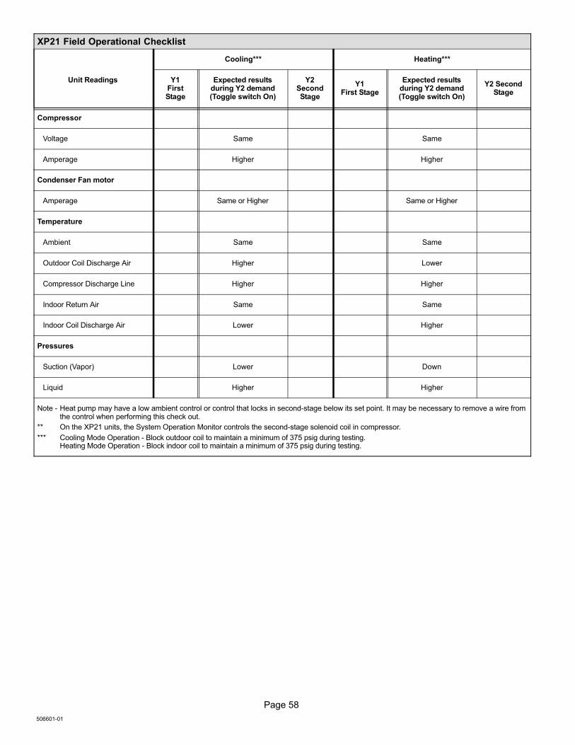
Page 58
506601−01
XP21 Field Operational Checklist
Unit Readings
Cooling*** Heating***
Y1FirstStage
Expected resultsduring Y2 demand(Toggle switch On)
Y2SecondStage
Y1First Stage
Expected resultsduring Y2 demand(Toggle switch On)
Y2 SecondStage
Compressor
Voltage Same Same
Amperage Higher Higher
Condenser Fan motor
Amperage Same or Higher Same or Higher
Temperature
Ambient Same Same
Outdoor Coil Discharge Air Higher Lower
Compressor Discharge Line Higher Higher
Indoor Return Air Same Same
Indoor Coil Discharge Air Lower Higher
Pressures
Suction (Vapor) Lower Down
Liquid Higher Higher
Note − Heat pump may have a low ambient control or control that locks in second−stage below its set point. It may be necessary to remove a wire fromthe control when performing this check out.
** On the XP21 units, the System Operation Monitor controls the second−stage solenoid coil in compressor.
*** Cooling Mode Operation − Block outdoor coil to maintain a minimum of 375 psig during testing.Heating Mode Operation − Block indoor coil to maintain a minimum of 375 psig during testing.
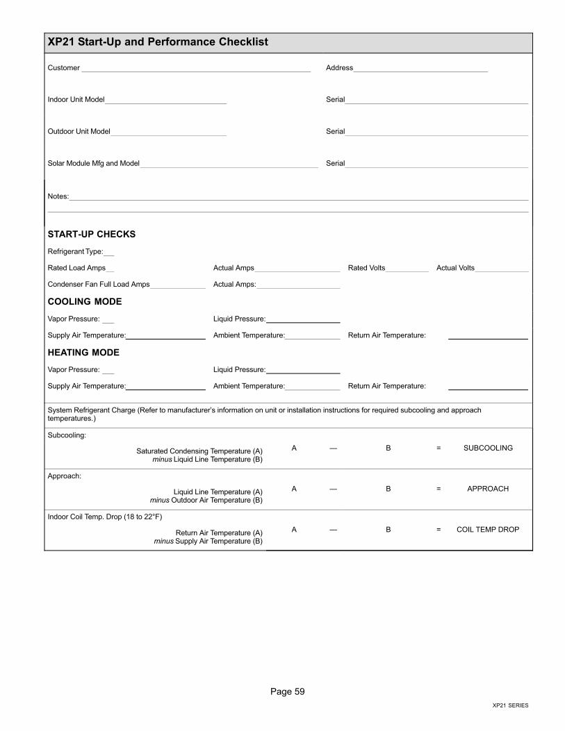
Page 59
XP21 SERIES
XP21 Start−Up and Performance Checklist
Customer Address
Indoor Unit Model Serial
Outdoor Unit Model Serial
Solar Module Mfg and Model Serial
Notes:
START−UP CHECKS
Refrigerant Type:
Rated Load Amps Actual Amps Rated Volts Actual Volts
Condenser Fan Full Load Amps Actual Amps:
COOLING MODE
Vapor Pressure: Liquid Pressure:
Supply Air Temperature: Ambient Temperature: Return Air Temperature:
HEATING MODE
Vapor Pressure: Liquid Pressure:
Supply Air Temperature: Ambient Temperature: Return Air Temperature:
System Refrigerant Charge (Refer to manufacturer’s information on unit or installation instructions for required subcooling and approachtemperatures.)
Subcooling:
A � B = SUBCOOLINGSaturated Condensing Temperature (A)minus Liquid Line Temperature (B)
Approach:
A � B = APPROACHLiquid Line Temperature (A)minus Outdoor Air Temperature (B)
Indoor Coil Temp. Drop (18 to 22°F)
A � B = COIL TEMP DROPReturn Air Temperature (A)minus Supply Air Temperature (B)