Embed Size (px)
Citation preview
Page 17/2012 506923−01
��������� ����������
�2012 Lennox Industries Inc.Dallas, Texas, USA
THIS MANUAL MUST BE LEFT WITH THEHOMEOWNER FOR FUTURE REFERENCE
WARNINGThe State of California has determined that this productmay contain or produce a chemical or chemicals, in verylow doses, which may cause serious illness or death. Itmay also cause cancer, birth defects, or reproductiveharm.
General
This XC21 outdoor unit is designed for use with HFC−410Arefrigerant only. This unit must be installed with an ap-proved indoor unit. See the Lennox XC21 Product Specifi-cations bulletin (EHB) for approved indoor componentmatch ups.
These instructions are intended as a general guide and donot supersede local codes in any way. Consult authoritieshaving jurisdiction before installation.
INSTALLATIONINSTRUCTIONS
Dave Lennox Signature®
Collection XC21 System
AIR CONDITIONERS506923−017/2012Supersedes 4/2012
WARNINGImproper installation, adjustment, alteration, service ormaintenance can cause property damage, personal inju-ry or loss of life.
Installation and service must be performed by a licensedprofessional installer (or equivalent) or service agency.
CAUTIONBefore attempting to perform any service or mainte-nance, turn the electrical power to unit OFF at discon-nect switch.
NOTICE !
For more in−depth information, consult the Installa-tion and Service Procedures manual, available asCorp.1007−L2 on DaveNet or through the TechnicalSupport department at 800−453−6669.
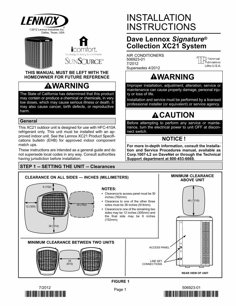
STEP 1 −− SETTING THE UNIT −− Clearances
CONTROLPANEL ACCESS
LOCATION
6 (152)
36 (914)
12 (305)30 (762)
24(610)
LINE SETCONNECTIONS
ACCESS PANEL
REAR VIEW OF UNIT
48 (1219)
MINIMUM CLEARANCE BETWEEN TWO UNITS
CLEARANCE ON ALL SIDES � INCHES (MILLIMETERS) MINIMUM CLEARANCEABOVE UNIT
NOTES:� Clearance to access panel must be 30
inches (762mm).
� Clearance to one of the other threesides must be 36 inches (914mm).
� Clearance to one of the remaining twosides may be 12 inches (305mm) andthe final side may be 6 inches(152mm).
FIGURE 1
Litho U.S.A.
Page 2
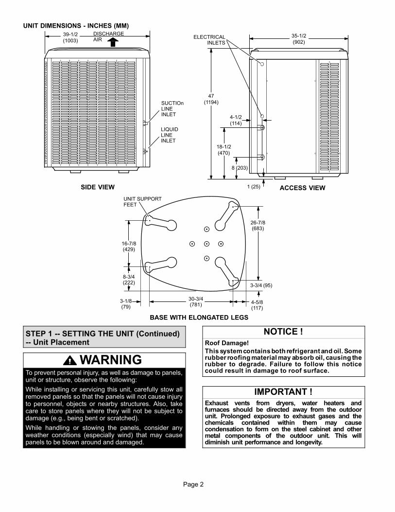
UNIT DIMENSIONS − INCHES (MM)
39−1/2
(1003)35−1/2
(902)
47
(1194)
18−1/2
(470)
8 (203)
1 (25)
4−1/2
(114)LIQUIDLINEINLET
ELECTRICALINLETS
SIDE VIEW ACCESS VIEW
DISCHARGEAIR
4−5/8(117)
BASE WITH ELONGATED LEGS
16−7/8(429)
8−3/4(222)
26−7/8(683)
3−3/4 (95)
30−3/4(781)
3−1/8(79)
SUCTIOnLINEINLET
UNIT SUPPORTFEET
STEP 1 −− SETTING THE UNIT (Continued)−− Unit Placement
WARNINGTo prevent personal injury, as well as damage to panels,unit or structure, observe the following:
While installing or servicing this unit, carefully stow allremoved panels so that the panels will not cause injuryto personnel, objects or nearby structures. Also, takecare to store panels where they will not be subject todamage (e.g., being bent or scratched).
While handling or stowing the panels, consider anyweather conditions (especially wind) that may causepanels to be blown around and damaged.
NOTICE !Roof Damage!
This system contains both refrigerant and oil. Somerubber roofing material may absorb oil, causing therubber to degrade. Failure to follow this noticecould result in damage to roof surface.
IMPORTANT !Exhaust vents from dryers, water heaters andfurnaces should be directed away from the outdoorunit. Prolonged exposure to exhaust gases and thechemicals contained within them may causecondensation to form on the steel cabinet and othermetal components of the outdoor unit. This willdiminish unit performance and longevity.
Page 3
XC21 SERIES
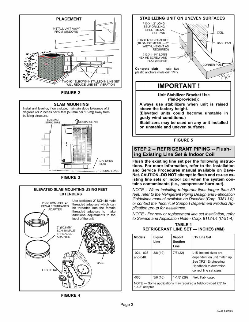
INSTALL UNIT AWAYFROM WINDOWS
TWO 90� ELBOWS INSTALLED IN LINE SETWILL REDUCE LINE SET VIBRATION
PLACEMENT
FIGURE 2
Install unit level or, if on a slope, maintain slope tolerance of 2degrees (or 2 inches per 5 feet [50 mm per 1.5 m]) away frombuilding structure.
GROUND LEVEL
MOUNTINGSLAB
BUILDINGSTRUCTURE DISCHARGE AIR
SLAB MOUNTING
FIGURE 3
LEG DETAIL
BASE
2" (50.8MM) SCH 40FEMALE THREADED
ADAPTER
ELEVATED SLAB MOUNTING USING FEET
EXTENDERS
2" (50.8MM)SCH 40 MALETHREADEDADAPTER
Use additional 2" SCH 40 malethreaded adapters which canbe threaded into the femalethreaded adapters to makeadditional adjustments to thelevel of the unit.
FIGURE 4
Unit Stabilizer Bracket Use(field−provided):
Always use stabilizers when unit is raisedabove the factory height. (Elevated units could become unstable ingusty wind conditions.)
Stabilizers may be used on any unit installedon unstable and uneven surfaces.
Concrete slab � use twoplastic anchors (hole drill 1/4")
COIL
BASE PAN
CORNER POST
STABILIZING BRACKET(18 GAUGE METAL � 2"
WIDTH; HEIGHT ASREQUIRED)
#10 X 1/2" LONGSELF−DRILLING
SHEET METALSCREWS
#10 X 1−1/4" LONGHEX HD SCREW AND
FLAT WASHER
STABILIZING UNIT ON UNEVEN SURFACES
! IMPORTANT !
FIGURE 5
STEP 2 −− REFRIGERANT PIPING −− Flush-ing Existing Line Set & Indoor Coil
Flush the existing line set per the following instruc-tions. For more information, refer to the Installationand Service Procedures manual available on Dave-Net. CAUTION − DO NOT attempt to flush and re−use ex-isting line sets or indoor coil when the system con-tains contaminants (i.e., compressor burn out).
NOTE − When installing refrigerant lines longer than 50feet, refer to the Refrigerant Piping Design and FabricationGuidelines manual available on DaveNet (Corp. 9351−L9),or contact the Technical Support Department Product Ap-plication group for assistance.
NOTE − For new or replacement line set installation, referto Service and Application Note − Corp. 9112−L4 (C−91−4).
TABLE 1REFRIGERANT LINE SET � INCHES (MM)
Models Liquid
Line
Vapor/
Suction
Line
L15 Line Set
−024, −036
and−048
3/8 (10) 7/8 (22) L15 line set sizes are
dependent on unit match up.
See XP21 Engineering
Handbook to determine
correct line set sizes.
−060 3/8 (10) 1−1/8� (29) Field Fabricated
NOTE � Some applications may required a field−provided 7/8" to1−1/8" adapter.
Page 4
IMPORTANT !
If this unit is being matched with an approved lineset or indoor unit coil that was previously chargedwith mineral oil, or if it is being matched with a coilwhich was manufactured before January of 1999,the coil and line set must be flushed prior to installa-tion. Take care to empty all existing traps. Polyol es-ter (POE) oils are used in Lennox units charged withHFC−410A refrigerant. Residual mineral oil can actas an insulator, preventing proper heat transfer. Itcan also clog the expansion device and reduce sys-tem performance and capacity.
Failure to properly flush the system per this instruc-tion and the detailed Installation and Service Proce-dures manual will void the warranty.
WARNINGWhen using a high pressure gas such asnitrogen to pressurize a refrigeration or airconditioning system, use a regulator thatcan control the pressure down to 1 or 2psig (6.9 to 13.8 kPa).
WARNINGRefrigerant can be harmful if it is inhaled. Refrigerantmust be used and recovered responsibly.
Failure to follow this warning may result in personal injuryor death.
WARNINGFire, Explosion and Personal Safety Haz-ard. Failure to follow this warning could re-sult in damage, personal injury or death.
Never use oxygen to pressurize or purgerefrigeration lines. Oxygen, when exposedto a spark or open flame, can cause fireand/or an explosion, that could result inproperty damage, personal injury or death.
WARNINGPolyol ester (POE) oils used with HFC−410Arefrigerant absorb moisture very quickly. It is veryimportant that the refrigerant system be kept closedas much as possible. DO NOT remove line set capsor service valve stub caps until you are ready to makeconnections.
IMPORTANT !Some scroll compressors have an internal vacuumprotector that will unload scrolls when suction pres-sure goes below 20 psig. A hissing sound will beheard when the compressor is running unloaded.Protector will reset when low pressure in system israised above 40 psig. DO NOT REPLACE COM-PRESSOR.
CAUTIONAs with any mechanical equipment, contact with sharpsheet metal edges can result in personal injury. Takecare while handling this equipment.
Page 5
XC21 SERIES
STEP 2 −− REFRIGERANT PIPING −− Removing Existing Indoor Metering Device
SENSINGLINE
TEFLON® RING
FIXED ORIFICE
BRASS NUT
LIQUID LINE ASSEMBLY(INCLUDES STRAINER)
LIQUID LINE ORIFICE HOUSING
DISTRIBUTOR TUBES
DISTRIBUTORASSEMBLY
REMOVE AND DISCARD
WHITE TEFLON® SEAL(IF PRESENT)
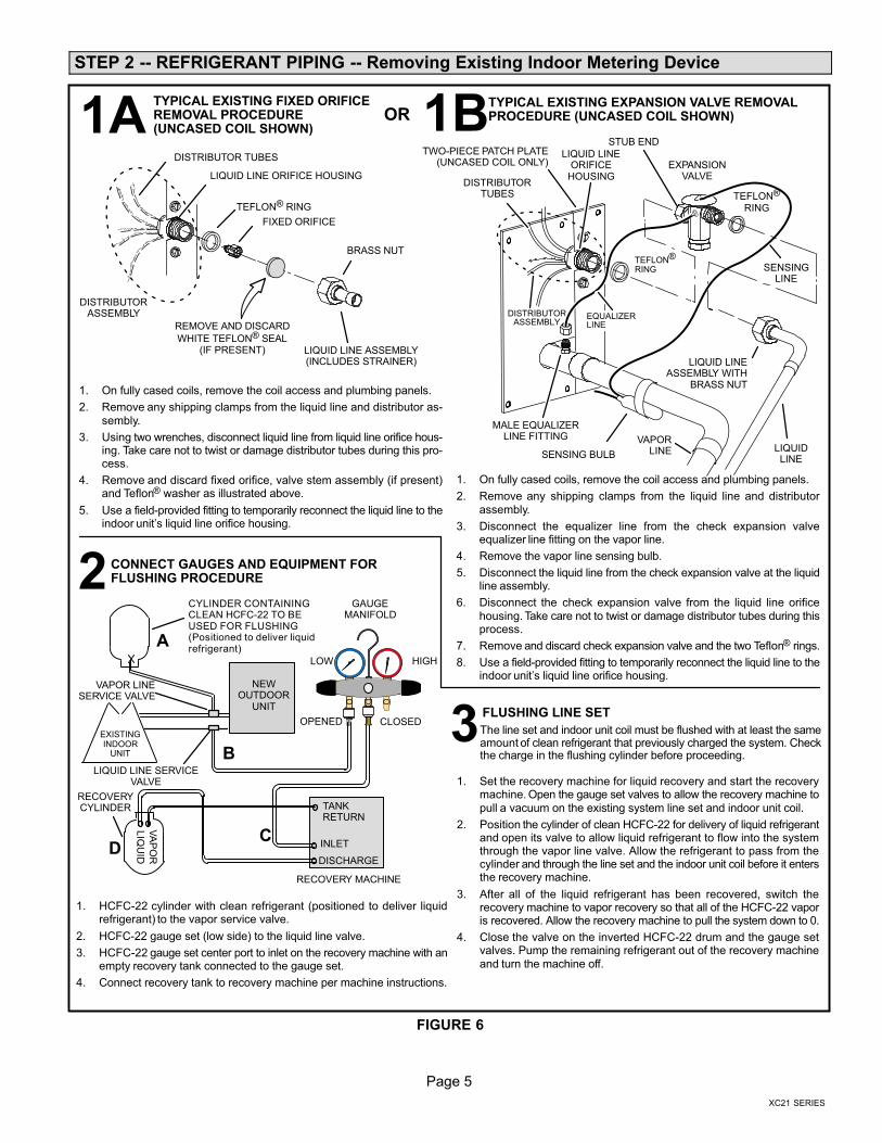
1. On fully cased coils, remove the coil access and plumbing panels.
2. Remove any shipping clamps from the liquid line and distributor as-sembly.
3. Using two wrenches, disconnect liquid line from liquid line orifice hous-ing. Take care not to twist or damage distributor tubes during this pro-cess.
4. Remove and discard fixed orifice, valve stem assembly (if present)and Teflon® washer as illustrated above.
5. Use a field−provided fitting to temporarily reconnect the liquid line to theindoor unit’s liquid line orifice housing.
TYPICAL EXISTING FIXED ORIFICEREMOVAL PROCEDURE (UNCASED COIL SHOWN)
TYPICAL EXISTING EXPANSION VALVE REMOVALPROCEDURE (UNCASED COIL SHOWN)
TWO−PIECE PATCH PLATE(UNCASED COIL ONLY)
VAPORLINE
DISTRIBUTORASSEMBLY
DISTRIBUTORTUBES
LIQUIDLINE
MALE EQUALIZERLINE FITTING
EQUALIZERLINE
EXPANSIONVALVE
TEFLON®
RING
STUB END
TEFLON®
RING
SENSING BULB
LIQUID LINEORIFICE
HOUSING
LIQUID LINEASSEMBLY WITH
BRASS NUT
1. On fully cased coils, remove the coil access and plumbing panels.
2. Remove any shipping clamps from the liquid line and distributorassembly.
3. Disconnect the equalizer line from the check expansion valveequalizer line fitting on the vapor line.
4. Remove the vapor line sensing bulb.
5. Disconnect the liquid line from the check expansion valve at the liquidline assembly.
6. Disconnect the check expansion valve from the liquid line orificehousing. Take care not to twist or damage distributor tubes during thisprocess.
7. Remove and discard check expansion valve and the two Teflon® rings.
8. Use a field−provided fitting to temporarily reconnect the liquid line to theindoor unit’s liquid line orifice housing.
LOW HIGH
EXISTINGINDOOR
UNIT
GAUGEMANIFOLD
CYLINDER CONTAININGCLEAN HCFC−22 TO BEUSED FOR FLUSHING(Positioned to deliver liquidrefrigerant)
LIQUID LINE SERVICEVALVE
INLET
DISCHARGE
TANKRETURN
CLOSEDOPENED
RECOVERYCYLINDER
RECOVERY MACHINE
NEWOUTDOOR
UNIT
VAPOR LINESERVICE VALVE
VA
PO
R
LIQ
UID
1
1. HCFC−22 cylinder with clean refrigerant (positioned to deliver liquidrefrigerant) to the vapor service valve.
2. HCFC−22 gauge set (low side) to the liquid line valve.
3. HCFC−22 gauge set center port to inlet on the recovery machine with anempty recovery tank connected to the gauge set.
4. Connect recovery tank to recovery machine per machine instructions.
CONNECT GAUGES AND EQUIPMENT FORFLUSHING PROCEDURE
A
B
CD
B
OR
FLUSHING LINE SET
1. Set the recovery machine for liquid recovery and start the recoverymachine. Open the gauge set valves to allow the recovery machine topull a vacuum on the existing system line set and indoor unit coil.
2. Position the cylinder of clean HCFC−22 for delivery of liquid refrigerantand open its valve to allow liquid refrigerant to flow into the systemthrough the vapor line valve. Allow the refrigerant to pass from thecylinder and through the line set and the indoor unit coil before it entersthe recovery machine.
3. After all of the liquid refrigerant has been recovered, switch therecovery machine to vapor recovery so that all of the HCFC−22 vaporis recovered. Allow the recovery machine to pull the system down to 0.
4. Close the valve on the inverted HCFC−22 drum and the gauge setvalves. Pump the remaining refrigerant out of the recovery machineand turn the machine off.
The line set and indoor unit coil must be flushed with at least the sameamount of clean refrigerant that previously charged the system. Checkthe charge in the flushing cylinder before proceeding.
1A
2
3
1B
FIGURE 6
Page 6
STEP 2 −− REFRIGERANT PIPING −− Brazing Procedures
ATTACH THE MANIFOLD GAUGE SET FOR BRAZINGLIQUID AND SUCTION / VAPOR LINE SERVICE VALVES
OUTDOORUNIT
LIQUID LINE
SUCTION / VAPORLINE
LIQUID LINE SERVICEVALVE
SUCTION /VAPOR LINE
SERVICEVALVE
ATTACHGAUGES
INDOORUNIT
SUCTION / VAPOR SERVICE PORT MUST BEOPEN AND SERVICE PORT CORE REMOVED
TO ALLOW EXIT POINT FOR NITROGEN FLOW
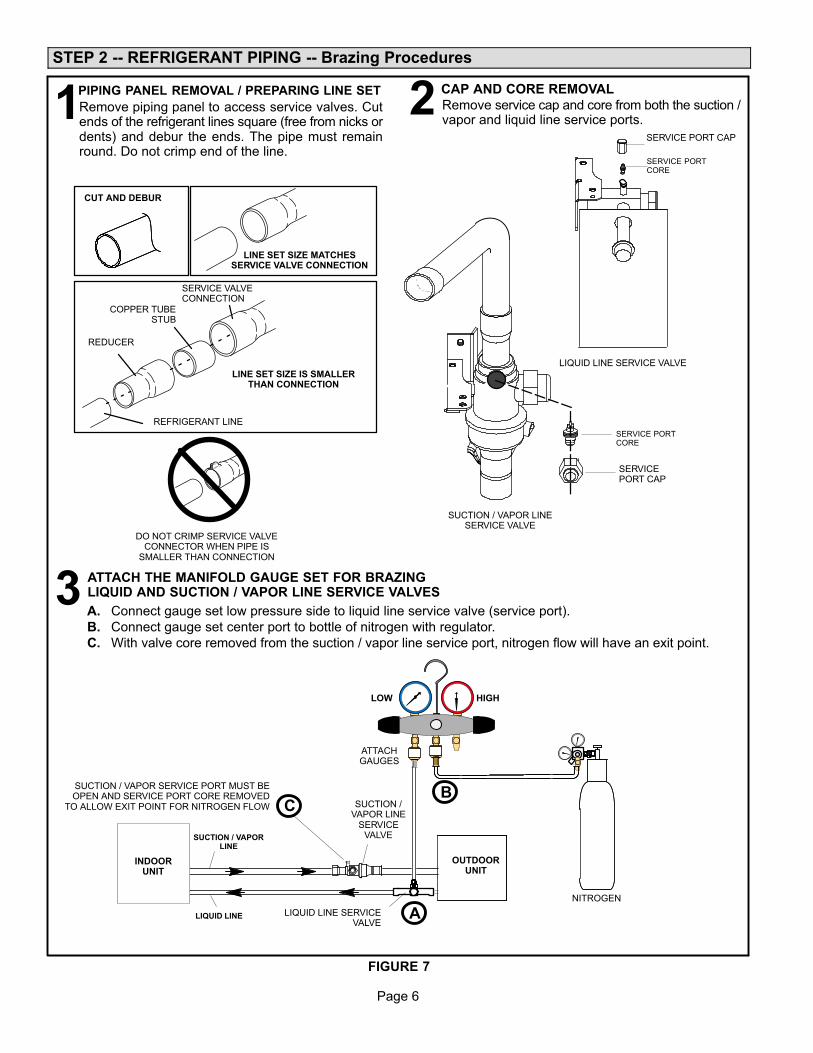
A. Connect gauge set low pressure side to liquid line service valve (service port).
B. Connect gauge set center port to bottle of nitrogen with regulator.
C. With valve core removed from the suction / vapor line service port, nitrogen flow will have an exit point.
NITROGEN
HIGHLOW
B
A
C
PIPING PANEL REMOVAL / PREPARING LINE SET CAP AND CORE REMOVAL
Remove piping panel to access service valves. Cutends of the refrigerant lines square (free from nicks ordents) and debur the ends. The pipe must remainround. Do not crimp end of the line.
Remove service cap and core from both the suction /vapor and liquid line service ports.1 2
LIQUID LINE SERVICE VALVE
SERVICE PORTCORE
SERVICE PORT CAP
SERVICE PORTCORE
SERVICEPORT CAP
CUT AND DEBUR
LINE SET SIZE MATCHESSERVICE VALVE CONNECTION
COPPER TUBESTUB
SERVICE VALVECONNECTION
REFRIGERANT LINE
DO NOT CRIMP SERVICE VALVECONNECTOR WHEN PIPE IS
SMALLER THAN CONNECTION
REDUCER
3
SUCTION / VAPOR LINESERVICE VALVE
LINE SET SIZE IS SMALLERTHAN CONNECTION
FIGURE 7
Page 7
XC21 SERIES
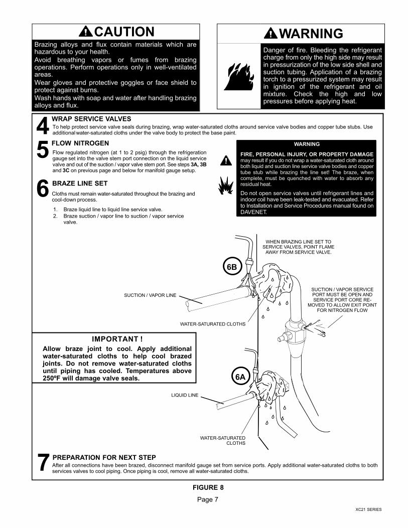
CAUTIONBrazing alloys and flux contain materials which arehazardous to your health.
Avoid breathing vapors or fumes from brazingoperations. Perform operations only in well−ventilatedareas.
Wear gloves and protective goggles or face shield toprotect against burns.
Wash hands with soap and water after handling brazingalloys and flux.
WARNINGDanger of fire. Bleeding the refrigerantcharge from only the high side may resultin pressurization of the low side shell andsuction tubing. Application of a brazingtorch to a pressurized system may resultin ignition of the refrigerant and oilmixture. Check the high and lowpressures before applying heat.
BRAZE LINE SET
Cloths must remain water−saturated throughout the brazing andcool−down process.
6
After all connections have been brazed, disconnect manifold gauge set from service ports. Apply additional water−saturated cloths to bothservices valves to cool piping. Once piping is cool, remove all water−saturated cloths.
PREPARATION FOR NEXT STEP7
WRAP SERVICE VALVESTo help protect service valve seals during brazing, wrap water−saturated cloths around service valve bodies and copper tube stubs. Useadditional water−saturated cloths under the valve body to protect the base paint.4FLOW NITROGEN
Flow regulated nitrogen (at 1 to 2 psig) through the refrigerationgauge set into the valve stem port connection on the liquid servicevalve and out of the suction / vapor valve stem port. See steps 3A, 3Band 3C on previous page and below for manifold gauge setup.
5
SUCTION / VAPOR LINE
WHEN BRAZING LINE SET TOSERVICE VALVES, POINT FLAME
AWAY FROM SERVICE VALVE.
LIQUID LINE
WATER−SATURATEDCLOTHS
WATER−SATURATED CLOTHS
6A
6B
SUCTION / VAPOR SERVICEPORT MUST BE OPEN ANDSERVICE PORT CORE RE-
MOVED TO ALLOW EXIT POINTFOR NITROGEN FLOW
IMPORTANT !
Allow braze joint to cool. Apply additionalwater−saturated cloths to help cool brazedjoints. Do not remove water−saturated clothsuntil piping has cooled. Temperatures above250ºF will damage valve seals.
WARNING
FIRE, PERSONAL INJURY, OR PROPERTY DAMAGEmay result if you do not wrap a water−saturated cloth aroundboth liquid and suction line service valve bodies and coppertube stub while brazing the line set! The braze, whencomplete, must be quenched with water to absorb anyresidual heat.
Do not open service valves until refrigerant lines andindoor coil have been leak−tested and evacuated. Referto Installation and Service Procedures manual found onDAVENET.
1. Braze liquid line to liquid line service valve.
2. Braze suction / vapor line to suction / vapor servicevalve.
FIGURE 8
Page 8
STEP 3 −− INSTALLING INDOOR EXPANSION VALVE
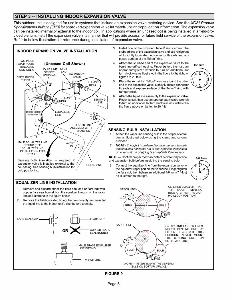
This outdoor unit is designed for use in systems that include an expansion valve metering device. See the XC21 ProductSpecifications bulletin (EHB) for approved expansion valve kit match−ups and application information. The expansion valvecan be installed internal or external to the indoor coil. In applications where an uncased coil is being installed in a field−pro-vided plenum, install the expansion valve in a manner that will provide access for future field service of the expansion valve.Refer to below illustration for reference during installation of expansion valve.
TWO−PIECEPATCH PLATE
(UNCASEDCOIL ONLY)
VAPORLINE
LIQUID LINEORIFICE
HOUSINGDISTRIBUTOR
TUBES
LIQUID LINE
MALE EQUALIZER LINEFITTING (SEE
EQUALIZER LINEINSTALLATION FOR
DETAILS)
SENSINGLINE
EQUALIZERLINE
EXPANSIONVALVE
TEFLON®
RING
(Uncased Coil Shown)
Sensing bulb insulation is required ifexpansion valve is installed external to thecoil casing. See sensing bulb installation forbulb positioning.
STUBEND
TEFLON®
RING
LIQUID LINEASSEMBLY WITH
BRASS NUT
DISTRIBUTORASSEMBLY
ON 7/8" AND LARGER LINES,MOUNT SENSING BULB ATEITHER THE 4 OR 8 O’CLOCKPOSITION. NEVER MOUNTTHE SENSING BULB ONBOTTOM OF LINE.
12
ON LINES SMALLER THAN7/8", MOUNT SENSINGBULB AT EITHER THE 3 OR9 O’CLOCK POSITION.
12
BULB
VAPOR LINE
VAPOR LINE
NOTE � NEVER MOUNT THE SENSINGBULB ON BOTTOM OF LINE.
BULB
BULBBULB
VAPOR LINE
FLARE NUT
COPPER FLARESEAL BONNET
MALE BRASS EQUALIZERLINE FITTING
FLARE SEAL CAP
OR
123
4567
8910
11 12
1/2 Turn
SENSING BULB INSTALLATION
EQUALIZER LINE INSTALLATION
123
4567
8910
11 12
1/8 Turn
1. Remove and discard either the flare seal cap or flare nut withcopper flare seal bonnet from the equalizer line port on the vaporline as illustrated in the figure below.
2. Remove the field−provided fitting that temporarily reconnectedthe liquid line to the indoor unit’s distributor assembly.
INDOOR EXPANSION VALVE INSTALLATION 3. Install one of the provided Teflon® rings around the
stubbed end of the expansion valve and use refrigerantoil to lightly lubricate the connector threads and ex-posed surface of the Teflon® ring.
4. Attach the stubbed end of the expansion valve to theliquid line orifice housing. Finger tighten, then use anappropriately sized wrench to turn an additional 1/2turn clockwise as illustrated in the figure to the right, ortighten to 20 ft−lb.
5. Place the remaining Teflon® washer around the otherend of the expansion valve. Lightly lubricate connectorthreads and expose surface of the Teflon® ring withrefrigerant oil.
6. Attach the liquid line assembly to the expansion valve.Finger tighten, then use an appropriately sized wrenchto turn an additional 1/2 turn clockwise as illustrated inthe figure above or tighten to 20 ft−lb.
1. Attach the vapor line sensing bulb in the proper orienta-tion as illustrated below using the clamp and screwsprovided.
2. NOTE − Though it is preferred to have the sensing bulbinstalled on a horizontal run of the vapor line, installationon a vertical run of piping is acceptable if necessary.
NOTE � Confirm proper thermal contact between vapor lineand expansion bulb before insulating the sensing bulb.
3. Connect the equalizer line from the expansion valve tothe equalizer vapor port on the vapor line. Finger tightenthe flare nut, then tighten an additional 1/8 turn (7 ft−lbs)as illustrated to the right.
FIGURE 9
Page 9
XC21 SERIES
STEP 4 −− LEAK TEST AND EVACUATION
TO VAPORSERVICE VALVE
HFC−410A
MANIFOLD GAUGE SET
OUTDOOR UNIT
HIGHLOW
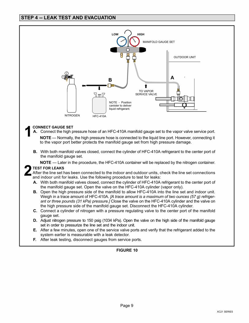
CONNECT GAUGE SET
A. Connect the high pressure hose of an HFC−410A manifold gauge set to the vapor valve service port.
NOTE � Normally, the high pressure hose is connected to the liquid line port. However, connecting itto the vapor port better protects the manifold gauge set from high pressure damage.
B. With both manifold valves closed, connect the cylinder of HFC−410A refrigerant to the center port ofthe manifold gauge set.
NOTE � Later in the procedure, the HFC−410A container will be replaced by the nitrogen container.
TEST FOR LEAKS
After the line set has been connected to the indoor and outdoor units, check the line set connectionsand indoor unit for leaks. Use the following procedure to test for leaks:
A. With both manifold valves closed, connect the cylinder of HFC−410A refrigerant to the center port ofthe manifold gauge set. Open the valve on the HFC−410A cylinder (vapor only).
B. Open the high pressure side of the manifold to allow HFC−410A into the line set and indoor unit.Weigh in a trace amount of HFC−410A. [A trace amount is a maximum of two ounces (57 g) refriger-ant or three pounds (31 kPa) pressure.] Close the valve on the HFC−410A cylinder and the valve onthe high pressure side of the manifold gauge set. Disconnect the HFC−410A cylinder.
C. Connect a cylinder of nitrogen with a pressure regulating valve to the center port of the manifoldgauge set.
D. Adjust nitrogen pressure to 150 psig (1034 kPa). Open the valve on the high side of the manifold gaugeset in order to pressurize the line set and the indoor unit.
E. After a few minutes, open one of the service valve ports and verify that the refrigerant added to thesystem earlier is measurable with a leak detector.
F. After leak testing, disconnect gauges from service ports.
1
2
AB
NITROGEN
NOTE − Positioncanister to deliverliquid refrigerant.
FIGURE 10
Page 10
STEP 4 −− LEAK TEST AND EVACUATION (Continued)
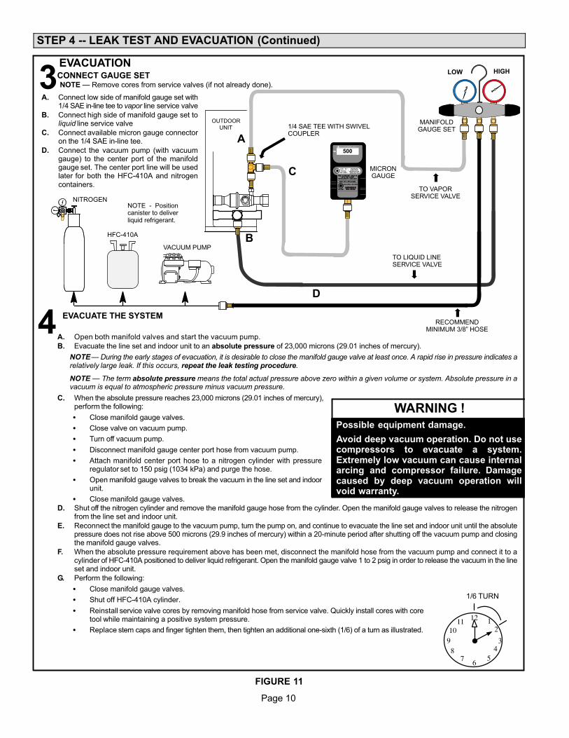
A. Open both manifold valves and start the vacuum pump.
B. Evacuate the line set and indoor unit to an absolute pressure of 23,000 microns (29.01 inches of mercury).
NOTE � During the early stages of evacuation, it is desirable to close the manifold gauge valve at least once. A rapid rise in pressure indicates arelatively large leak. If this occurs, repeat the leak testing procedure.
NOTE � The term absolute pressure means the total actual pressure above zero within a given volume or system. Absolute pressure in avacuum is equal to atmospheric pressure minus vacuum pressure.
C. When the absolute pressure reaches 23,000 microns (29.01 inches of mercury),perform the following:
� Close manifold gauge valves.
� Close valve on vacuum pump.
� Turn off vacuum pump.
� Disconnect manifold gauge center port hose from vacuum pump.
� Attach manifold center port hose to a nitrogen cylinder with pressureregulator set to 150 psig (1034 kPa) and purge the hose.
� Open manifold gauge valves to break the vacuum in the line set and indoorunit.
� Close manifold gauge valves.
D. Shut off the nitrogen cylinder and remove the manifold gauge hose from the cylinder. Open the manifold gauge valves to release the nitrogenfrom the line set and indoor unit.
E. Reconnect the manifold gauge to the vacuum pump, turn the pump on, and continue to evacuate the line set and indoor unit until the absolutepressure does not rise above 500 microns (29.9 inches of mercury) within a 20−minute period after shutting off the vacuum pump and closingthe manifold gauge valves.
F. When the absolute pressure requirement above has been met, disconnect the manifold hose from the vacuum pump and connect it to acylinder of HFC−410A positioned to deliver liquid refrigerant. Open the manifold gauge valve 1 to 2 psig in order to release the vacuum in the lineset and indoor unit.
G. Perform the following:
� Close manifold gauge valves.
� Shut off HFC−410A cylinder.
� Reinstall service valve cores by removing manifold hose from service valve. Quickly install cores with coretool while maintaining a positive system pressure.
� Replace stem caps and finger tighten them, then tighten an additional one−sixth (1/6) of a turn as illustrated.
OUTDOOR
UNIT
TO VAPORSERVICE VALVE
TO LIQUID LINESERVICE VALVE
MICRONGAUGE
VACUUM PUMP
1/4 SAE TEE WITH SWIVELCOUPLER
500
MANIFOLDGAUGE SET
HFC−410A
RECOMMENDMINIMUM 3/8" HOSE
A. Connect low side of manifold gauge set with1/4 SAE in−line tee to vapor line service valve
B. Connect high side of manifold gauge set toliquid line service valve
C. Connect available micron gauge connectoron the 1/4 SAE in−line tee.
D. Connect the vacuum pump (with vacuumgauge) to the center port of the manifoldgauge set. The center port line will be usedlater for both the HFC−410A and nitrogencontainers.
HIGHLOW
12
34
56
78
910
11 12
1/6 TURN
NITROGEN
3CONNECT GAUGE SET
A
B
C
D
4 EVACUATE THE SYSTEM
NOTE � Remove cores from service valves (if not already done).
Possible equipment damage.
Avoid deep vacuum operation. Do not usecompressors to evacuate a system.Extremely low vacuum can cause internalarcing and compressor failure. Damagecaused by deep vacuum operation willvoid warranty.
WARNING !
NOTE − Positioncanister to deliverliquid refrigerant.
EVACUATION
FIGURE 11
Page 11
XC21 SERIES
STEP 5 −− ELECTRICAL −− Circuit Sizing and Wire Routing
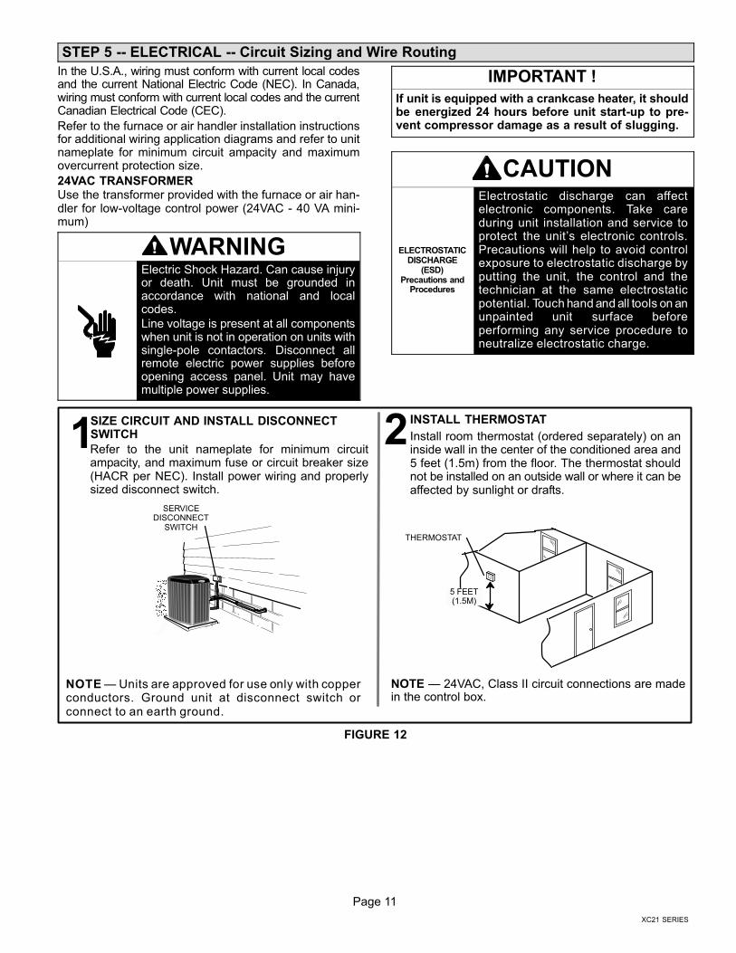
In the U.S.A., wiring must conform with current local codesand the current National Electric Code (NEC). In Canada,wiring must conform with current local codes and the currentCanadian Electrical Code (CEC).
Refer to the furnace or air handler installation instructionsfor additional wiring application diagrams and refer to unitnameplate for minimum circuit ampacity and maximumovercurrent protection size.
24VAC TRANSFORMERUse the transformer provided with the furnace or air han-dler for low-voltage control power (24VAC − 40 VA mini-mum)
WARNINGElectric Shock Hazard. Can cause injuryor death. Unit must be grounded inaccordance with national and localcodes.
Line voltage is present at all componentswhen unit is not in operation on units withsingle-pole contactors. Disconnect allremote electric power supplies beforeopening access panel. Unit may havemultiple power supplies.
IMPORTANT !
If unit is equipped with a crankcase heater, it shouldbe energized 24 hours before unit start−up to pre-vent compressor damage as a result of slugging.
CAUTION
ELECTROSTATICDISCHARGE
(ESD)Precautions and
Procedures
Electrostatic discharge can affectelectronic components. Take careduring unit installation and service toprotect the unit’s electronic controls.Precautions will help to avoid controlexposure to electrostatic discharge byputting the unit, the control and thetechnician at the same electrostaticpotential. Touch hand and all tools on anunpainted unit surface beforeperforming any service procedure toneutralize electrostatic charge.
Refer to the unit nameplate for minimum circuitampacity, and maximum fuse or circuit breaker size(HACR per NEC). Install power wiring and properlysized disconnect switch.
NOTE � Units are approved for use only with copperconductors. Ground unit at disconnect switch orconnect to an earth ground.
SIZE CIRCUIT AND INSTALL DISCONNECTSWITCH1
NOTE � 24VAC, Class II circuit connections are madein the control box.
Install room thermostat (ordered separately) on aninside wall in the center of the conditioned area and5 feet (1.5m) from the floor. The thermostat shouldnot be installed on an outside wall or where it can beaffected by sunlight or drafts.
THERMOSTAT
INSTALL THERMOSTAT
2
SERVICEDISCONNECT
SWITCH
5 FEET(1.5M)
FIGURE 12
Page 12
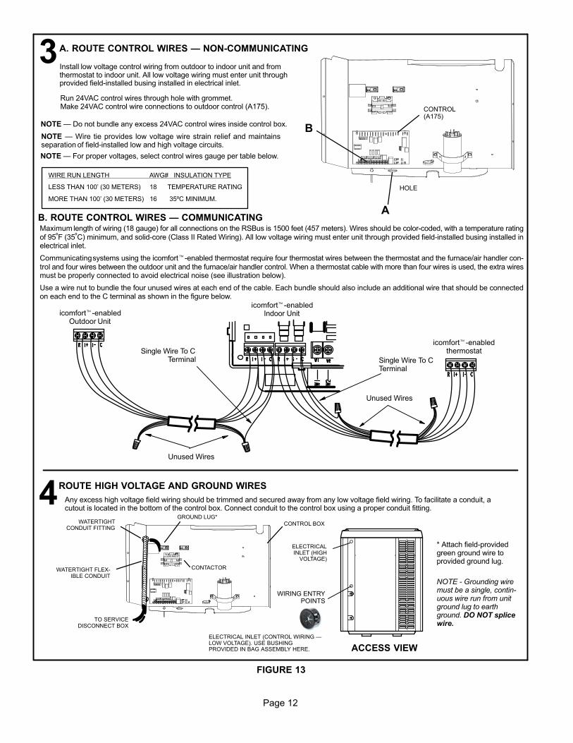
NOTE � For proper voltages, select control wires gauge per table below.
WIRE RUN LENGTH AWG# INSULATION TYPE
LESS THAN 100’ (30 METERS) 18 TEMPERATURE RATING
MORE THAN 100’ (30 METERS) 16 35ºC MINIMUM.
NOTE � Wire tie provides low voltage wire strain relief and maintainsseparation of field−installed low and high voltage circuits.
NOTE � Do not bundle any excess 24VAC control wires inside control box.
A. ROUTE CONTROL WIRES � NON−COMMUNICATING
CONTROL(A175)
HOLE
Install low voltage control wiring from outdoor to indoor unit and fromthermostat to indoor unit. All low voltage wiring must enter unit throughprovided field−installed busing installed in electrical inlet.
3Run 24VAC control wires through hole with grommet.Make 24VAC control wire connections to outdoor control (A175).
B. ROUTE CONTROL WIRES � COMMUNICATINGMaximum length of wiring (18 gauge) for all connections on the RSBus is 1500 feet (457 meters). Wires should be color−coded, with a temperature ratingof 95ºF (35ºC) minimum, and solid−core (Class II Rated Wiring). All low voltage wiring must enter unit through provided field−installed busing installed inelectrical inlet.
Communicating systems using the icomfort�−enabled thermostat require four thermostat wires between the thermostat and the furnace/air handler con-trol and four wires between the outdoor unit and the furnace/air handler control. When a thermostat cable with more than four wires is used, the extra wiresmust be properly connected to avoid electrical noise (see illustration below).
Use a wire nut to bundle the four unused wires at each end of the cable. Each bundle should also include an additional wire that should be connectedon each end to the C terminal as shown in the figure below.
Any excess high voltage field wiring should be trimmed and secured away from any low voltage field wiring. To facilitate a conduit, acutout is located in the bottom of the control box. Connect conduit to the control box using a proper conduit fitting.
ROUTE HIGH VOLTAGE AND GROUND WIRES
CONTROL BOX
GROUND LUG*
CONTACTOR
WATERTIGHTCONDUIT FITTING
WATERTIGHT FLEX-IBLE CONDUIT
TO SERVICEDISCONNECT BOX
ACCESS VIEW
ELECTRICALINLET (HIGH
VOLTAGE)
WIRING ENTRYPOINTS
ELECTRICAL INLET (CONTROL WIRING �LOW VOLTAGE). USE BUSHINGPROVIDED IN BAG ASSEMBLY HERE.
4
icomfort�−enabledthermostat
icomfort�−enabledOutdoor Unit
Single Wire To CTerminal
Unused Wires
Unused Wires
* Attach field−provided green ground wire toprovided ground lug.
NOTE − Grounding wiremust be a single, contin-uous wire run from unitground lug to earthground. DO NOT splicewire.
A
B
Single Wire To CTerminal
icomfort�−enabledIndoor Unit
FIGURE 13
Page 13
XC21 SERIES
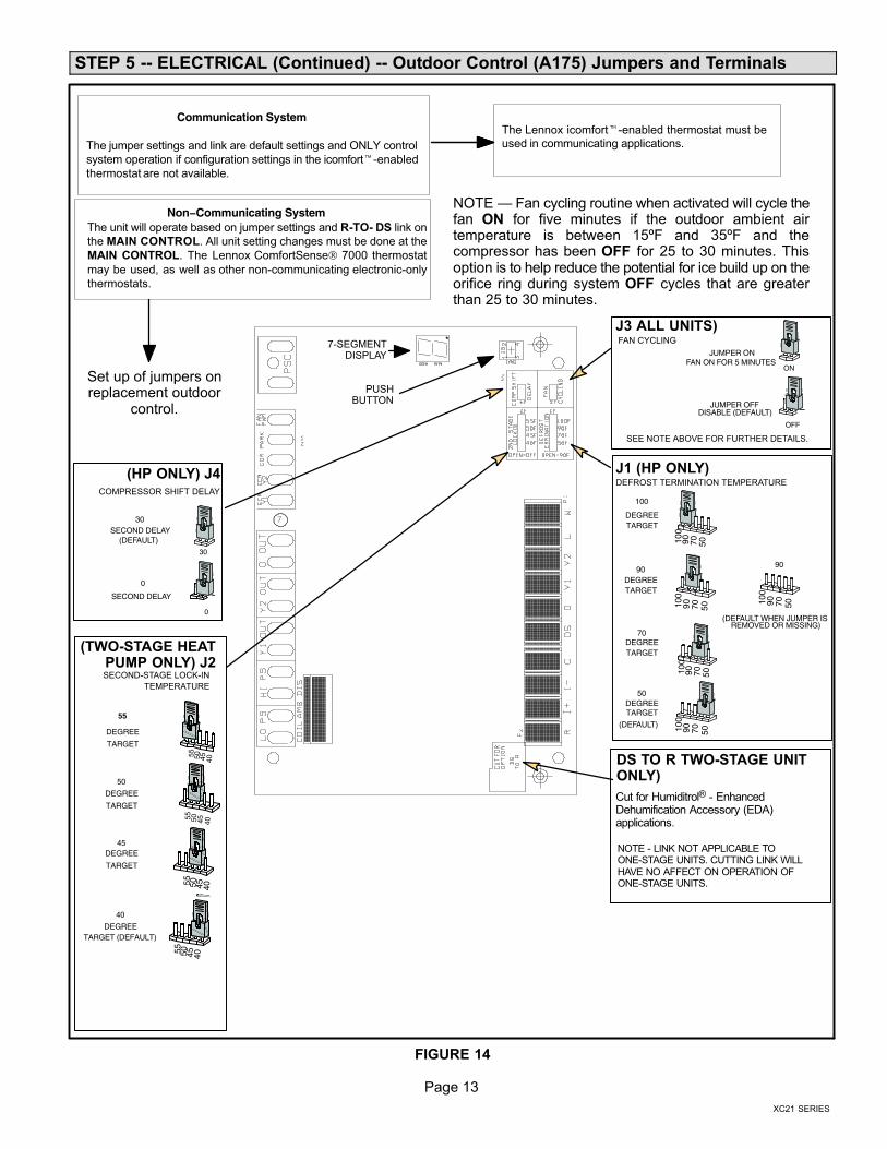
STEP 5 −− ELECTRICAL (Continued) −− Outdoor Control (A175) Jumpers and Terminals
55
50
DEGREE
TARGET
45DEGREE
TARGET
40
DEGREETARGET (DEFAULT)
55 50 45 4055 50 45 40
55 50 45 40
55 50 45 40
DEGREE
TARGET
100
90DEGREETARGET
70DEGREETARGET
50DEGREETARGET
100
90 70 50
DEGREETARGET
100
90 70 50
100
90 70 50
100
90 70 50
30
0
30SECOND DELAY
SECOND DELAY
0
Cut for Humiditrol® − EnhancedDehumification Accessory (EDA)applications.
SECOND−STAGE LOCK−IN
TEMPERATURE
(HP ONLY) J4 J1 (HP ONLY)
J3 ALL UNITS)
DS TO R TWO−STAGE UNITONLY)
(TWO−STAGE HEATPUMP ONLY) J2
DEFROST TERMINATION TEMPERATURECOMPRESSOR SHIFT DELAY
FAN CYCLING
ON
OFF
JUMPER ON FAN ON FOR 5 MINUTES
DISABLE (DEFAULT)JUMPER OFF
(DEFAULT)
SEE NOTE ABOVE FOR FURTHER DETAILS.
100
90 70 50
(DEFAULT)
(DEFAULT WHEN JUMPER IS REMOVED OR MISSING)
90
Non−Communicating SystemThe unit will operate based on jumper settings and R−TO− DS link on
the MAIN CONTROL. All unit setting changes must be done at the
MAIN CONTROL. The Lennox ComfortSense 7000 thermostat
may be used, as well as other non−communicating electronic−only
thermostats.
Communication System
The jumper settings and link are default settings and ONLY control
system operation if configuration settings in the icomfort�−enabled
thermostat are not available.
The Lennox icomfort�−enabled thermostat must beused in communicating applications.
7−SEGMENTDISPLAY
PUSHBUTTON
Set up of jumpers onreplacement outdoor
control.
NOTE − LINK NOT APPLICABLE TOONE−STAGE UNITS. CUTTING LINK WILLHAVE NO AFFECT ON OPERATION OFONE−STAGE UNITS.
NOTE � Fan cycling routine when activated will cycle thefan ON for five minutes if the outdoor ambient airtemperature is between 15ºF and 35ºF and thecompressor has been OFF for 25 to 30 minutes. Thisoption is to help reduce the potential for ice build up on theorifice ring during system OFF cycles that are greaterthan 25 to 30 minutes.
FIGURE 14
Page 14
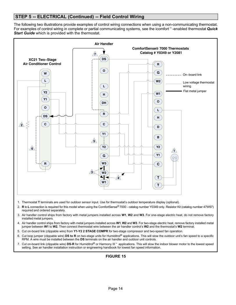
STEP 5 −− ELECTRICAL (Continued) −− Field Control Wiring
The following two illustrations provide examples of control wiring connections when using a non−communicating thermostat.For examples of control wiring in complete or partial communicating systems, see the icomfort�−enabled thermostat QuickStart Guide which is provided with the thermostat.
Y1
O
R
W1
G
D
R
Y1
L
C
C
B
Y2
Y2
W
O
DS
L
T
T
W2
H
W3
H
O
C
L
Y2
DS
DH
G
R
Y1
W2
W1
1
2
5
6
7
ComfortSense� 7000 Thermostats Catalog # Y0349 or Y2081
On−board link
Low voltage thermostat wiring
Flat metal jumper
4
3
Air Handler
XC21 Two−Stage Air Conditioner Control
1. Thermostat T terminals are used for outdoor sensor input. Use for thermostat’s outdoor temperature display (optional).
2. R to L connection is required for this model when using the ComfortSense® 7000 − catalog number Y0349 only. Resistor Kit (catalog number 47W97)required and ordered separately.
3. Air handler control ships from factory with metal jumpers installed across W1, W2 and W3. For one−stage electric heat, do not remove factoryinstalled metal jumpers.
4. Air handler control ships from factory with metal jumpers installed across W1, W2 and W3. For two−stage electric heat, remove factory installed metaljumper between W1 to W2. Then connect thermostat wire between the air handler control’s W2 and the thermostat’s W2 terminal.
5. Cut on−board link (clippable wire) from Y1−Y2 2 STAGE COMPR for two−stage compressor and two−speed fan operation.
6. Cut loop jumper (clippable wire) DS to R on two−stage units for Humiditrol® applications. This will slow the outdoor unit’s fan speed to a specificRPM. A wire must be installed between the DS terminals on the air handler and outdoor unit controls.
7. Cut on−board link (clippable wire) DS−R for Humiditrol® or Harmony III� applications. This will slow the indoor blower motor to the lowest speedsetting. See air handler installation instruction or engineering handbook for lowest fan speed information.
FIGURE 15
Page 15
XC21 SERIES
Y1
O
R
W1
G
D
R
Y1
L
C
C
B
Y2
Y2
W
O
DS
L
T
T
W2
H
H
O
C
L
Y2
DS
DH
G
R
Y1
W2
W1
1
2
4
5
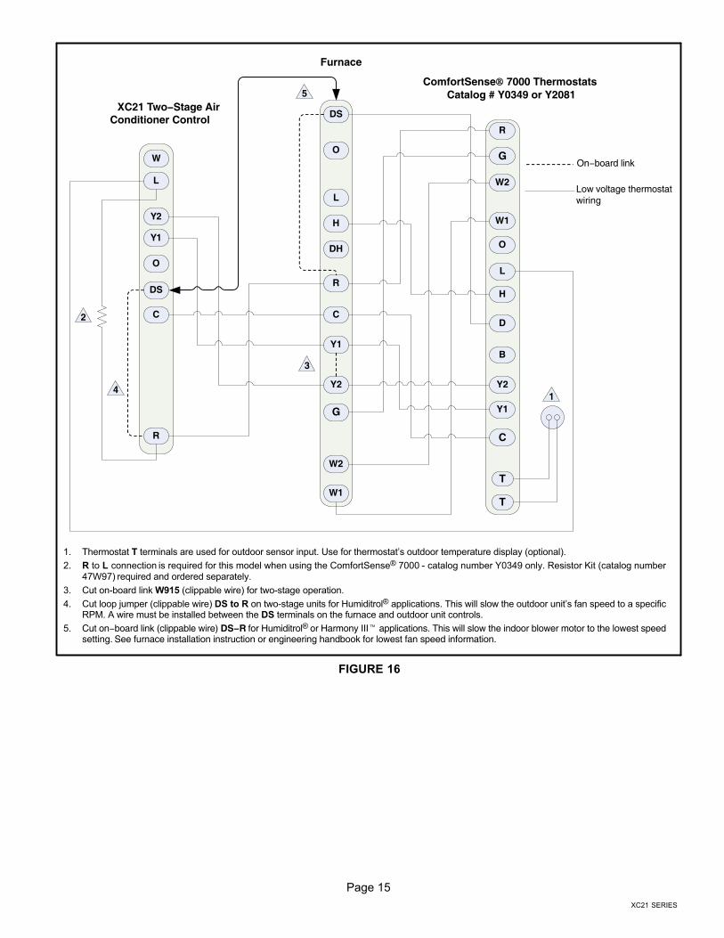
Furnace
ComfortSense� 7000 Thermostats Catalog # Y0349 or Y2081
XC21 Two−Stage AirConditioner Control
On−board link
Low voltage thermostat wiring
3
1. Thermostat T terminals are used for outdoor sensor input. Use for thermostat’s outdoor temperature display (optional).
2. R to L connection is required for this model when using the ComfortSense® 7000 − catalog number Y0349 only. Resistor Kit (catalog number47W97) required and ordered separately.
3. Cut on−board link W915 (clippable wire) for two−stage operation.
4. Cut loop jumper (clippable wire) DS to R on two−stage units for Humiditrol® applications. This will slow the outdoor unit’s fan speed to a specificRPM. A wire must be installed between the DS terminals on the furnace and outdoor unit controls.
5. Cut on−board link (clippable wire) DS−R for Humiditrol® or Harmony III� applications. This will slow the indoor blower motor to the lowest speedsetting. See furnace installation instruction or engineering handbook for lowest fan speed information.
FIGURE 16
Page 16
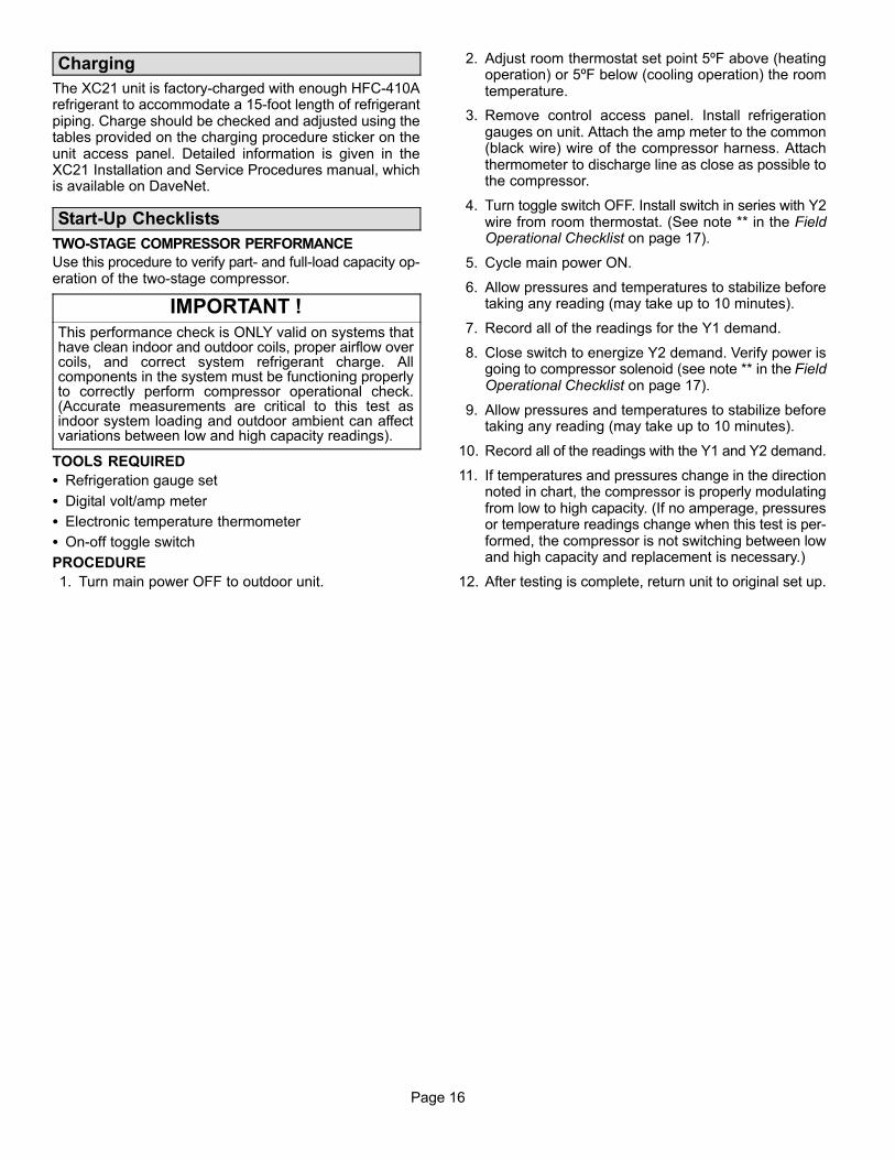
Charging
The XC21 unit is factory−charged with enough HFC−410Arefrigerant to accommodate a 15−foot length of refrigerantpiping. Charge should be checked and adjusted using thetables provided on the charging procedure sticker on theunit access panel. Detailed information is given in theXC21 Installation and Service Procedures manual, whichis available on DaveNet.
Start−Up Checklists
TWO−STAGE COMPRESSOR PERFORMANCE
Use this procedure to verify part- and full-load capacity op-eration of the two-stage compressor.
IMPORTANT !This performance check is ONLY valid on systems thathave clean indoor and outdoor coils, proper airflow overcoils, and correct system refrigerant charge. Allcomponents in the system must be functioning properlyto correctly perform compressor operational check.(Accurate measurements are critical to this test asindoor system loading and outdoor ambient can affectvariations between low and high capacity readings).
TOOLS REQUIRED
� Refrigeration gauge set
� Digital volt/amp meter
� Electronic temperature thermometer
� On-off toggle switch
PROCEDURE
1. Turn main power OFF to outdoor unit.
2. Adjust room thermostat set point 5ºF above (heatingoperation) or 5ºF below (cooling operation) the roomtemperature.
3. Remove control access panel. Install refrigerationgauges on unit. Attach the amp meter to the common(black wire) wire of the compressor harness. Attachthermometer to discharge line as close as possible tothe compressor.
4. Turn toggle switch OFF. Install switch in series with Y2wire from room thermostat. (See note ** in the FieldOperational Checklist on page 17).
5. Cycle main power ON.
6. Allow pressures and temperatures to stabilize beforetaking any reading (may take up to 10 minutes).
7. Record all of the readings for the Y1 demand.
8. Close switch to energize Y2 demand. Verify power isgoing to compressor solenoid (see note ** in the FieldOperational Checklist on page 17).
9. Allow pressures and temperatures to stabilize beforetaking any reading (may take up to 10 minutes).
10. Record all of the readings with the Y1 and Y2 demand.
11. If temperatures and pressures change in the directionnoted in chart, the compressor is properly modulatingfrom low to high capacity. (If no amperage, pressuresor temperature readings change when this test is per-formed, the compressor is not switching between lowand high capacity and replacement is necessary.)
12. After testing is complete, return unit to original set up.
Page 17
XC21 SERIES
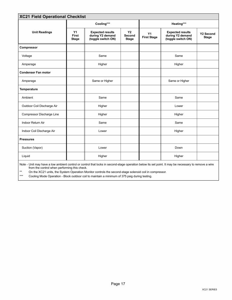
XC21 Field Operational Checklist
Unit Readings
Cooling*** Heating***
Y1FirstStage
Expected resultsduring Y2 demand(toggle switch ON)
Y2SecondStage
Y1First Stage
Expected resultsduring Y2 demand(toggle switch ON)
Y2 SecondStage
Compressor
Voltage Same Same
Amperage Higher Higher
Condenser Fan motor
Amperage Same or Higher Same or Higher
Temperature
Ambient Same Same
Outdoor Coil Discharge Air Higher Lower
Compressor Discharge Line Higher Higher
Indoor Return Air Same Same
Indoor Coil Discharge Air Lower Higher
Pressures
Suction (Vapor) Lower Down
Liquid Higher Higher
Note − Unit may have a low ambient control or control that locks in second−stage operation below its set point. It may be necessary to remove a wirefrom the control when performing this check.
** On the XC21 units, the System Operation Monitor controls the second−stage solenoid coil in compressor.
*** Cooling Mode Operation − Block outdoor coil to maintain a minimum of 375 psig during testing.
Page 18
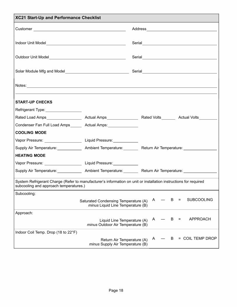
XC21 Start−Up and Performance Checklist
Customer Address
Indoor Unit Model Serial
Outdoor Unit Model Serial
Solar Module Mfg and Model Serial
Notes:
START−UP CHECKS
Refrigerant Type:
Rated Load Amps Actual Amps Rated Volts Actual Volts
Condenser Fan Full Load Amps Actual Amps:
COOLING MODE
Vapor Pressure: Liquid Pressure:
Supply Air Temperature: Ambient Temperature: Return Air Temperature:
HEATING MODE
Vapor Pressure: Liquid Pressure:
Supply Air Temperature: Ambient Temperature: Return Air Temperature:
System Refrigerant Charge (Refer to manufacturer’s information on unit or installation instructions for requiredsubcooling and approach temperatures.)
Subcooling:
A � B = SUBCOOLINGSaturated Condensing Temperature (A)minus Liquid Line Temperature (B)
Approach:
A � B = APPROACHLiquid Line Temperature (A)minus Outdoor Air Temperature (B)
Indoor Coil Temp. Drop (18 to 22°F)
A � B = COIL TEMP DROPReturn Air Temperature (A)minus Supply Air Temperature (B)
Page 19
XC21 SERIES
Homeowner Information
CAUTIONBefore attempting to perform any service or mainte-nance, turn the electrical power to unit OFF at discon-nect switch.
Cleaning of the outdoor unit’s coil should be performed bya licensed professional service technician (or equivalent).Contact your dealer and set up a schedule (preferablytwice a year, but at least once a year) to inspect and ser-vice your outdoor unit. The following maintenance may beperformed by the homeowner.
IMPORTANT !
Sprinklers and soaker hoses should not be installedwhere they could cause prolonged exposure to theoutdoor unit by treated water. Prolonged exposureof the unit to treated water (i.e., sprinkler systems,soakers, waste water, etc.) will corrode the surfaceof steel and aluminum parts, diminish performanceand affect longevity of the unit.
Outdoor CoilThe outdoor unit must be properly maintained to ensure itsproper operation.
� Please contact your dealer to schedule proper inspec-tion and maintenance for your equipment.
� Make sure no obstructions restrict airflow to the outdoorunit.
� Grass clippings, leaves, or shrubs crowding the unit can
cause the unit to work harder and use more energy.
� Keep shrubbery trimmed away from the unit and periodi-
cally check for debris which collects around the unit.
� Keep snow level below the louvered panels to ensure
proper performance.
Routine Maintenance
In order to ensure peak performance, your system must beproperly maintained. Clogged filters and blocked airflowprevent your unit from operating at its most efficient level.
NOTE � The filter and all access panels must be in placeany time the unit is in operation. If you are unsure about thefilter required for your system, call your Lennox dealer forassistance.
1. Ask your Lennox dealer to show you where your indoorunit’s filter is located. It will be either at the indoor unit(installed internal or external to the cabinet) or behinda return air grille in the wall or ceiling. Check the filtermonthly and clean or replace it as needed.
2. Disposable filters should be replaced with a filter of thesame type and size.
3. The indoor evaporator coil is equipped with a drain panto collect condensate formed as your system removeshumidity from the inside air. Have your dealer showyou the location of the drain line and how to check forobstructions. (This would also apply to an auxiliarydrain, if installed.)
Thermostat Operation
See the ComfortSense® 7000 or icomfort�−enabled ther-mostat homeowner manual for instructions on how to oper-ate your thermostat.
Preservice Check
If your system fails to operate, check the following beforecalling for service:
� Verify room thermostat settings are correct.
� Verify that all electrical disconnect switches are ON.
� Check for any blown fuses or tripped circuit breakers.
� Verify unit access panels are in place.
� Verify air filter is clean.
� If service is needed, locate and write down the unit
model number and have it handy before calling.