Embed Size (px)
Citation preview
This document covers the installation, operation and maintenance of the Series 3800 E-Ball Rotary Control Valves presented in the “Series 3800 Product Specification”. The 3800 Series Rotary Globe Control Valve incorporates the time-tested and proven Segmented Ball–Eccentric Geometry design (E-Ball), combining exceptionally tight control and rangeability (100:1), with superior trim wear characteristics inherent with the eccentric design. Available as completely automated valve assemblies with the highest quality actuators and accessories or as bare stem product ready for your automation needs, the 3800 Series comes in a wide variety of standard options for body/trim materials and construction
builds, from Class IV to Class VI shut off. The ever-popular TTZ Ceramic Trim is an off-the-shelf choice for erosive or corrosive fluids and a vast array of custom alloys can be selected for custom construction, engineered to your specific application needs. The 3800 can flow in the forward direction, flow-to-open; or reverse direction, flow-to-close. The 3800 is available in a thru-shaft or split-shaft configuration. These features allow for maximum flexibility in matching benefits to your application. The 3800 offers a large combination of preferred piping positions and acceptable actuator orientations to provide maximum flexibility in mounting the valve in the piping.
TABLE OF CONTENTSOverview .............................................Cover
Valve Identification ...............................2-3
Information Present on Valves ..........4-5
Performance Characteristics .............6-7
Weights & Dimensions ...........................7
Installation & Operation ......................8-9
Actuator Removal ................................... 10
Maintenance ............................................ 11
Packing Adjustment .............................. 11
Parts / Overhaul ...................................... 12
Parts Kits ..............................................13-14
Drawings..............................................15-19
Installation Instructions & Maintenance Document
Series 38OOE-BALL ROTARY CONTROL VALVES
38
00
IOM
PRODUCT OVERVIEW
The instructions given herein cover generally the operation and maintenance of subject equipment. Should any questions arise which may not be answered specifically by these instructions, they should be referred to Warren Controls Inc. for further detailed information and technical assistance. This manual cannot possibly cover every situation connected with the operation, adjustment, inspection, test, overhaul and maintenance of the equipment furnished. Every effort is made to prepare the text of this manual
so that engineering and design data is transformed into the most easily understood wording. Warren Controls Inc., in furnishing this equipment and this manual, must presume that the operation and maintenance personnel assigned thereto have sufficient technical knowledge and experience to apply sound safety and operational practices which may not be covered herein. In applications where Warren Controls Inc. furnished equipment is to be integrated with a process or other machinery, these instructions should be
GENERAL INFORMATION
3800_IOM_RevB_0317
2 2600 Emrick Blvd • Bethlehem, PA 18020 • USA • 800-922-0085 • www.warrencontrols.com 3800_IOM_RevB_0317
thoroughly reviewed to determine the proper integration of the equipment into the overall plant operational procedures. Warren Controls does not assume responsibility for the selection, use, or
maintenance of any product. Responsibility for proper selection, use, and maintenance of any Warren Controls product remains solely with the purchaser and end-user.
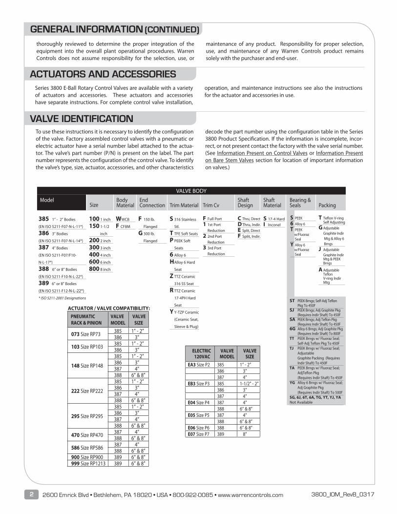
To use these instructions it is necessary to identify the configuration of the valve. Factory assembled control valves with a pneumatic or electric actuator have a serial number label attached to the actua-tor. The valve’s part number (P/N) is present on the label. The part number represents the configuration of the control valve. To identify the valve’s type, size, actuator, accessories, and other characteristics
decode the part number using the configuration table in the Series 3800 Product Specification. If the information is incomplete, incor-rect, or not present contact the factory with the valve serial number. (See Information Present on Control Valves or Information Present on Bare Stem Valves section for location of important information on valves.)
GENERAL INFORMATION (CONTINUED)
Series 3800 E-Ball Rotary Control Valves are available with a variety of actuators and accessories. These actuators and accessories have separate instructions. For complete control valve installation,
operation, and maintenance instructions see also the instructions for the actuator and accessories in use.
ACTUATORS AND ACCESSORIES
VALVE IDENTIFICATION
385 1” - 2” Bodies
(EN ISO 5211-F07-N-L-11*)
386 3” Bodies
(EN ISO 5211-F07-N-L-14*)
387 4” Bodies
(EN ISO 5211-F07/F10-
N-L-17*)
388 6” or 8” Bodies
(EN ISO 5211-F10-N-L-22*)
389 6” or 8” Bodies
(EN ISO 5211-F12-N-L-22*)
* ISO 5211-2001 Designations
SizeBody Material
End Connection
Shaft Material
100 1 inch
150 1-1/2
inch
200 2 inch
300 3 inch
400 4 inch
600 6 inch
800 8 inch
W WCB
F CF8M
Trim Cv
F Full Port1 1st Port Reduction2 2nd Port Reduction3 3rd Port Reduction
ShaftDesign
C Thru, DirectD Thru, Indir.E Split, DirectF Split, Indir.
F 150 lb.
Flanged
G 300 lb.
Flanged
Trim Material
S 316 Stainless
Stl.
T TFE Soft Seats
P PEEK Soft
Seats
6 Alloy 6
H Alloy 6 Hard
Seat
Z TTZ Ceramic
316 SS Seat
R TTZ Ceramic
17-4PH Hard
Seat
Y Y-TZP Ceramic
(Ceramic Seat,
Sleeve & Plug)
S 17-4 HardI Inconel
ModelPacking
Bearing & Seals
VALVE BODY
T Teflon V-ring Self AdjustingG Adjustable Graphite Indir Mtg & Alloy 6 BrngsJ Adjustable Graphite Indir Mtg & PEEK Brngs
A Adjustable Teflon V-ring Indir Mtg
S PEEK6 Alloy 6T PEEK w/Fluoraz SealY Alloy 6 w/Fluoraz Seal
ST PEEK Brngs; Self-Adj Teflon Pkg To 450FSJ PEEK Brngs; Adj Graphite Pkg (Requires Indir Shaft) To 450FSA PEEK Brngs; Adj Teflon Pkg (Requires Indir Shaft) To 450F6G Alloy 6 Brngs; Adj Graphite Pkg (Requires Indir Shaft) To 800FTT PEEK Brngs w/ Fluoraz Seal; Self-Adj Teflon Pkg To 450FTJ PEEK Brngs w/ Fluoraz Seal; Adjustable Graphite Packing (Requires Indir Shaft) To 450FTA PEEK Brngs w/ Fluoraz Seal; AdjTeflon Pkg (Requires Indir Shaft) To 450F YG Alloy 6 Brngs w/ Fluoraz Seal; Adj Graphite Pkg (Requires Indir Shaft) To 500FSG, 6J, 6T, 6A, TG, YT, YJ, YA Not Available
ACTUATOR / VALVE COMPATIBILITY: PNEUMATIC RACK & PINION
VALVEMODEL
VALVE SIZE
073 Size RP73 385 1” - 2” 386 3”
103 Size RP103 385 1” - 2” 386 3”
148 Size RP148
385 1” - 2” 386 3” 387 4” 388 6” & 8”
222 Size RP222
385 1” - 2” 386 3” 387 4” 388 6” & 8”
295 Size RP295
385 1” - 2” 386 3” 387 4” 388 6” & 8”
470 Size RP470 387 4” 388 6” & 8”
586 Size RP586 387 4” 388 6” & 8”
900 Size RP900 389 6” & 8” 999 Size RP1213 389 6” & 8”
ELECTRIC 120VAC
VALVE MODEL
VALVESIZE
EA3 Size P2 385 1” - 2”386 3”387 4”
EB3 Size P3 385 1-1/2” - 2”386 3”387 4”
E04 Size P4 387 4” 388 6” & 8”
E05 Size P5 387 4”388 6” & 8”
E06 Size P6 388 6” & 8” E07 Size P7 389 8”
3Series 3800 3800_IOM_RevB_0317
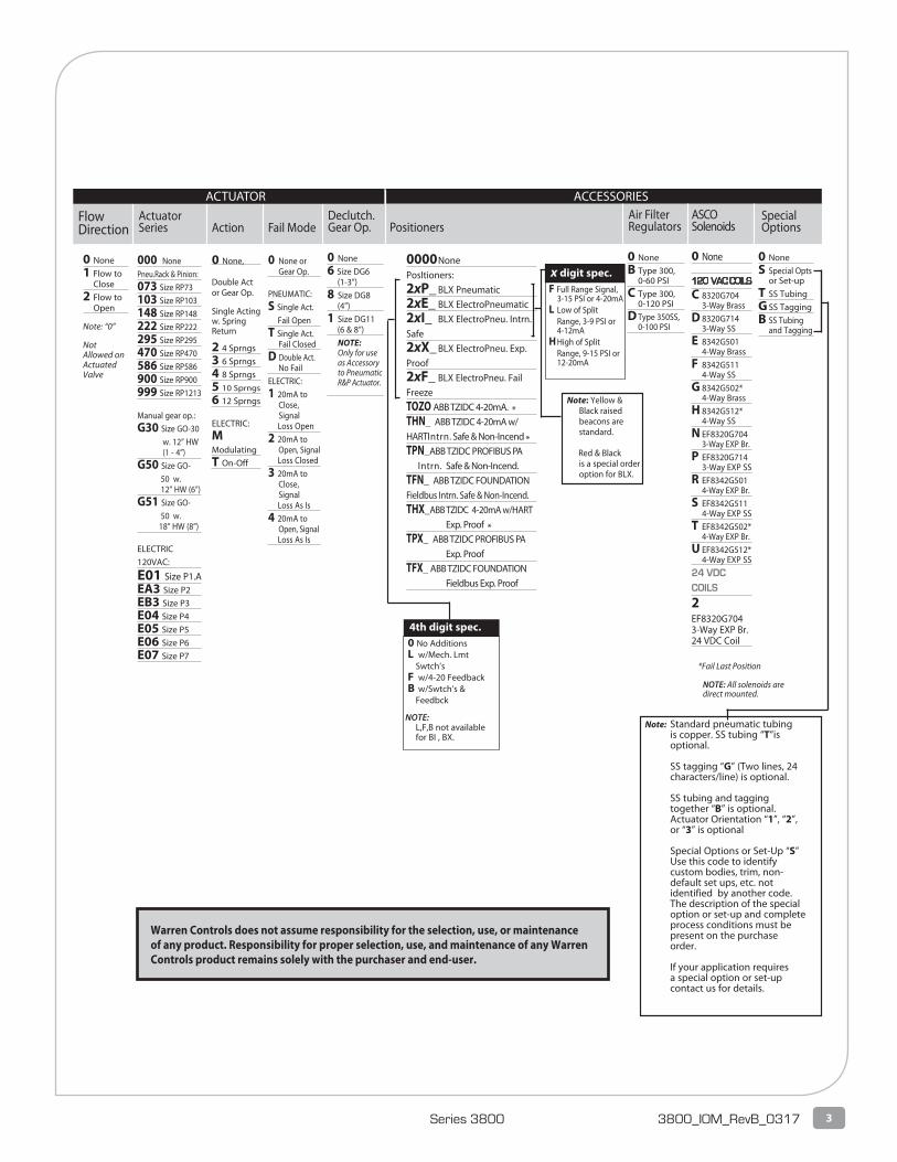
ActuatorSeries Action Fail Mode
FlowDirection
Declutch. Gear Op. Positioners
Air FilterRegulators
SpecialOptions
ASCO Solenoids
0 None, Double Act or Gear Op.
Single Acting w. Spring Return 2 4 Sprngs 3 6 Sprngs 4 8 Sprngs 5 10 Sprngs
6 12 Sprngs ELECTRIC: M ModulatingT On-Off
000 NonePneu.Rack & Pinion:073 Size RP73 103 Size RP103 148 Size RP148 222 Size RP222 295 Size RP295 470 Size RP470 586 Size RP586 900 Size RP900999 Size RP1213 Manual gear op.: G30 Size GO-30 w. 12” HW (1 - 4”)G50 Size GO- 50 w. 12” HW (6”)G51 Size GO- 50 w. 18” HW (8”) ELECTRIC 120VAC:
E01 Size P1.AEA3 Size P2EB3 Size P3E04 Size P4E05 Size P5E06 Size P6E07 Size P7
0 None or Gear Op. PNEUMATIC: S Single Act. Fail OpenT Single Act. Fail Closed D Double Act. No FailELECTRIC: 1 20mA to Close, Signal Loss Open2 20mA to Open, Signal Loss Closed3 20mA to Close, Signal Loss As Is4 20mA to Open, Signal Loss As Is
0 None 1 Flow to Close2 Flow to Open
Note: “0”
NotAllowed on Actuated Valve
0 None6 Size DG6 (1-3”)8 Size DG8 (4”)1 Size DG11 (6 & 8”) NOTE: Only for use as Accessory to Pneumatic R&P Actuator.
0 NoneB Type 300, 0-60 PSIC Type 300, 0-120 PSID Type 350SS, 0-100 PSI
0 None
120 VAC COILS
C 8320G704 3-Way BrassD 8320G714 3-Way SSE 8342G501 4-Way BrassF 8342G511 4-Way SSG 8342G502* 4-Way BrassH 8342G512* 4-Way SSN EF8320G704 3-Way EXP Br.P EF8320G714 3-Way EXP SSR EF8342G501 4-Way EXP Br.S EF8342G511 4-Way EXP SST EF8342G502* 4-Way EXP Br.U EF8342G512* 4-Way EXP SS24 VDC COILS
2 EF8320G704 3-Way EXP Br. 24 VDC Coil
0 NoneS Special Opts or Set-upT SS TubingG SS TaggingB SS Tubing and Tagging
Note: Yellow & Black raised beacons are standard.
Red & Black
is a special order option for BLX.
0 No Additions L w/Mech. Lmt Swtch’s F w/4-20 Feedback B w/Swtch’s & Feedbck
NOTE: L,F,B not available for BI , BX.
4th digit spec.
F Full Range Signal, 3-15 PSI or 4-20mA L Low of Split Range, 3-9 PSI or 4-12mA H High of Split Range, 9-15 PSI or 12-20mA
x digit spec.
Note: Standard pneumatic tubing is copper. SS tubing “T”is optional.
SS tagging “G” (Two lines, 24 characters/line) is optional.
SS tubing and tagging together “B” is optional. Actuator Orientation “1”, “2”, or “3” is optional
Special Options or Set-Up “S” Use this code to identify
custom bodies, trim, non-default set ups, etc. not identified by another code. The description of the special option or set-up and complete process conditions must be present on the purchase order.
If your application requires a special option or set-up contact us for details.
*Fail Last Position
NOTE: All solenoids are direct mounted.
ACTUATOR ACCESSORIES
Warren Controls does not assume responsibility for the selection, use, or maintenance of any product. Responsibility for proper selection, use, and maintenance of any Warren Controls product remains solely with the purchaser and end-user.
0000 NonePosItioners: 2xP_ BLX Pneumatic2xE_ BLX ElectroPneumatic2xI_ BLX ElectroPneu. Intrn. Safe2xX_ BLX ElectroPneu. Exp.Proof2xF_ BLX ElectroPneu. Fail FreezeTOZO ABB TZIDC 4-20mA. *THN_ ABB TZIDC 4-20mA w/HARTIntrn. Safe & Non-Incend *TPN_ABB TZIDC PROFIBUS PA Intrn. Safe & Non-Incend. TFN_ ABB TZIDC FOUNDATION Fieldbus Intrn. Safe & Non-Incend.THX_ABB TZIDC 4-20mA w/HART Exp. Proof *TPX_ ABB TZIDC PROFIBUS PA Exp. ProofTFX_ ABB TZIDC FOUNDATION Fieldbus Exp. Proof
4 2600 Emrick Blvd • Bethlehem, PA 18020 • USA • 800-922-0085 • www.warrencontrols.com 3800_IOM_RevB_0317
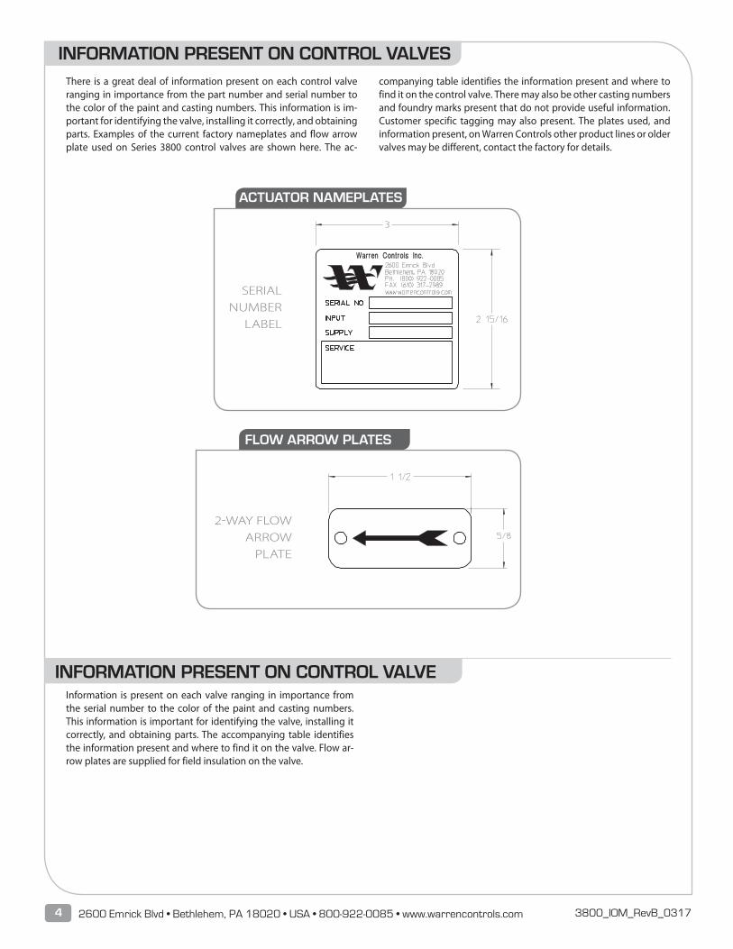
There is a great deal of information present on each control valve ranging in importance from the part number and serial number to the color of the paint and casting numbers. This information is im-portant for identifying the valve, installing it correctly, and obtaining parts. Examples of the current factory nameplates and flow arrow plate used on Series 3800 control valves are shown here. The ac-
companying table identifies the information present and where to find it on the control valve. There may also be other casting numbers and foundry marks present that do not provide useful information. Customer specific tagging may also present. The plates used, and information present, on Warren Controls other product lines or older valves may be different, contact the factory for details.
SERIAL NUMBER
LABEL
2-WAY FLOW ARROW
PLATE
Information is present on each valve ranging in importance from the serial number to the color of the paint and casting numbers. This information is important for identifying the valve, installing it correctly, and obtaining parts. The accompanying table identifies the information present and where to find it on the valve. Flow ar-row plates are supplied for field insulation on the valve.
INFORMATION PRESENT ON CONTROL VALVES
INFORMATION PRESENT ON CONTROL VALVE
ACTUATOR NAMEPLATES
FLOW ARROW PLATES
5Series 3800 3800_IOM_RevB_0317
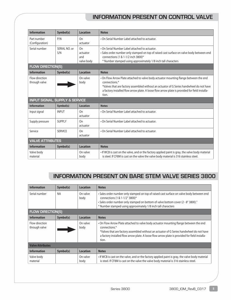
Information Symbol(s) Location Notes
Serial number NA On valve body
• Sales order number only stamped on top of raised cast surface on valve body between end connections (1 & 1-1/2” 3800)*
• Sales order number only stamped on bottom of valve bottom cover (2 - 8” 3800).”* Number stamped using approximately 1/8 inch tall characters
FLOW DIRECTION(S)
Information Symbol(s) Location Notes
Flow directionthrough valve
On valvebody
• On Flow Arrow Plate attached to valve body actuator mounting flange between the end connections.*
*Valves that are factory assembled without an actuator of G Series handwheel do not have a factory installed flow arrow plate. A loose flow arrow plate is provided for field installa-tion.
Valve Attributes
Information Symbol(s) Location Notes
Valve bodymaterial
On valvebody
• If WCB is cast on the valve, and or the factory applied paint is gray, the valve body material is steel. If CF8M is cast on the valve the valve body material is 316 stainless steel.
Information Symbol(s) Location Notes
Part number(Configuration)
P/N Onactuator
• On Serial Number Label attached to actuator.
Serial number SERIAL NO. or S/N
Onactuatorandvalve body
• On Serial Number Label attached to actuator.• Sales order number only stamped on top of raised cast surface on valve body between end
connections (1 & 1-1/2 inch 3800)* * Number stamped using approximately 1/8 inch tall characters
FLOW DIRECTION(S)
Information Symbol(s) Location Notes
Flow directionthrough valve
On valvebody
• On Flow Arrow Plate attached to valve body actuator mounting flange between the end connections.*
*Valves that are factory assembled without an actuator of G Series handwheel do not have a factory installed flow arrow plate. A loose flow arrow plate is provided for field installa-tion.
INPUT SIGNAL, SUPPLY & SERVICE
Information Symbol(s) Location Notes
Input signal INPUT On actuator
• On Serial Number Label attached to actuator.
Supply pressure SUPPLY Onactuator
• On Serial Number Label attached to actuator.
Service SERVICE Onactuator
• On Serial Number Label attached to actuator.
VALVE ATTRIBUTES
Information Symbol(s) Location Notes
Valve bodymaterial
On valvebody
• If WCB is cast on the valve, and or the factory applied paint is gray, the valve body material is steel. If CF8M is cast on the valve the valve body material is 316 stainless steel.
INFORMATION PRESENT ON CONTROL VALVE
INFORMATION PRESENT ON BARE STEM VALVE SERIES 3800
6 2600 Emrick Blvd • Bethlehem, PA 18020 • USA • 800-922-0085 • www.warrencontrols.com 3800_IOM_RevB_0317
PERFORMANCE CHARACTERISTICS
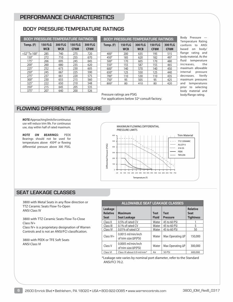
Body Pressure — Temperature Rating conform to ANSI based on body/flange rating and body material. As the fluid temperature increases, the maximum allowable internal pressure decreases. Verify maximum pressures and temperatures prior to selecting body material and body/flange rating.
3800 with Metal Seats in any flow direction or TTZ Ceramic Seats Flow-To-Open ANSI Class IV
3800 with TTZ Ceramic Seats Flow-To-Close Class IV+Class IV+ is a proprietary designation of Warren Controls and is not an ANSI/FCI classification. 3800 with PEEK or TFE Soft Seats ANSI Class VI
NOTE: Approaching limits for continuous use will reduce trim life. For continuous use, stay within half of rated maximum. NOTE ON BEARINGS: PEEK Bearings should not be used for temperatures above 450ºF or flowing differential pressure above 300 PSIG.
BODY PRESSURE-TEMPERATURE RATINGS:
Temp. (F) 150 FLGWCB
300 FLGWCB
150 FLGCF8M
300 FLGCF8M
+32° To 100° 285 740 275 720150° 272 710 255 670175° 266 695 245 645200° 260 680 235 620225° 252 673 230 605250° 245 667 225 590275° 237 661 220 575300° 230 655 215 560325° 222 650 210 548350° 215 645 205 535375° 207 640 200 526
BODY PRESSURE-TEMPERATURE RATINGS:
Temp. (F) 150 FLGWCB
300 FLGWCB
150 FLGCF8M
300 FLGCF8M
400° 200 635 195 515450° 185 620 182 497500° 170 605 170 480550° 155 587 155 465600° 140 570 140 450650° 125 550 125 440700° 110 530 110 435750° 95 505 95 425800° 80 410 80 420
Pressure ratings are PSIG For applications below 32º consult factory.
ALLOWABLE SEAT LEAKAGE CLASSES
Leakage RelativeSeat
Maximum Seat Leakage
Test Fluid
Test Pressure
Relative Seat Tightness
Class II 0.5% of rated CV Water 45 to 60 PSI 1Class III 0.1% of rated CV Water 45 to 60 PSI 5Class IV 0.01% of rated CV Water 45 to 60 PSI 50
Class IV+0.0015 ml/min/inch of trim size/∆P(PSI)
Water Max Operating ∆P 150,000
Class V0.0005 ml/min/inch of trim size/∆P(PSI)
Water Max Operating ∆P 300,000
Class VI Class VI about 0.9 ml/min* Air 50 PSI 600,000
*Leakage rate varies by nominal port diameter, refer to the Standard ANSI/FCI 70.2.
BODY PRESSURE-TEMPERATURE RATINGS
FLOWING DIFFERENTIAL PRESSURE
SEAT LEAKAGE CLASSES
7Series 3800 3800_IOM_RevB_0317
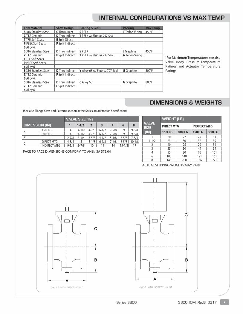
DIMENSIONS & WEIGHTS
DIMENSION (IN)
VALVE SIZE (IN)
1 1-1/2 2 3 4 6 8
A 150FLG 4 4-1/2 4-7/8 6-1/2 7-5/8 9 9-5/8300FLG 4 4-1/2 4-7/8 6-1/2 7-5/8 9 9-5/8
B 2-7/8 3-1/4 3-5/8 4-1/2 5-3/8 6-5/8 7-3/4
C DIRECT MTG 4-3/4 5 5-1/8 6-1/8 7-1/8 8-5/8 10-1/8INDIRECT MTG 9-5/8 9-7/8 10 11 14 15-1/2 17
VALVESIZE (IN)
WEIGHT (LB)
DIRECT MTG INDIRECT MTG
150FLG 300FLG 150FLG 300FLG1 20 22 29 31
1-1/2 23 30 32 392 20 25 29 343 35 50 44 594 55 80 76 1016 100 140 121 1618 145 200 166 221
FACE TO FACE DIMENSIONS CONFORM TO ANSI/ISA S75.04
ACTUAL SHIPPING WEIGHTS MAY VARY
(See also Flange Sizes and Patterns section in the Series 3800 Product Specifiction)
1For Maximum Temperatures see also Valve Body Pressure-Temperature Ratings and Actuator Temperature Ratings
Trim Material Shaft Design Bearing & Seals Packing Max Temp 1
S 316 Stainless Steel C Thru Direct S PEEK T Teflon V-ring 450°FZ TTZ Ceramic D Thru Indirect T PEEK w/ Fluoraz 797 Seal T TFE Soft Seats E Split Direct P PEEK Soft Seats F Split Indirect 6 Alloy 6 S 316 Stainless Steel D Thru Indirect S PEEK J Graphite 450°FZ TTZ Ceramic F Split Indirect T PEEK w/ Fluoraz 797 Seal A Teflon V-ringT TFE Soft Seats P PEEK Soft Seats 6 Alloy 6 S 316 Stainless Steel D Thru Indirect Y Alloy 6B w/ Fluoraz 797 Seal G Graphite 500°FZ TTZ Ceramic F Split Indirect6 Alloy 6 S 316 Stainless Steel D Thru Indirect 6 Alloy 6B G Graphite 800°FZ TTZ Ceramic F Split Indirect 6 Alloy 6
INTERNAL CONFIGURATIONS VS MAX TEMP
8 2600 Emrick Blvd • Bethlehem, PA 18020 • USA • 800-922-0085 • www.warrencontrols.com 3800_IOM_RevB_0317
See also separate actuator and accessory instructions for additional installation guidelines.
• Series 3800 E-Ball Rotary Control Valves are manu-factured to order for a specific set of process con-ditions. Warren Controls, Inc. maintains all original process information that each valve was manufac-tured to. This information is readily available with the valve serial number. Contact the appropriate department to verify 800-922-0085.
• Be sure that the fluid pressure, temperature, flow, and flowing differential pressure will not exceed the limits of the valve. (See the Body Pressure-Temperature Ratings, Internal Configurations vs. Max Temp, and Flowing Differential Pressure Lim-its sections.
• Be sure that the ambient temperature of the se-lected location will not exceed the maximum temperature of the actuator or accessories. Infor-mation can be found in the Product Specification regarding these limits.
• Follow good piping practices. Install a bypass around the valve. Install stop valves in inlet and outlet piping to provide means to isolate valve.
• Provide proper inlet and outlet drainage in steam service to prevent water hammer or possible ero-sion in equipment.
• Install gauges in inlet and outlet piping to provide means for checking adjustment and operation.
• For maximum efficiency and minimum wear install valve in a preferred position. (See Piping Orienta-tion and Actuator Mounting, Orientation, & Flow Direction sections in the Product Specification for preferred positions).
• Be sure to leave clearance to allow for actuator re-moval (See Dimensions & Weights section in 3800 Product Specification for actuator removal clear-ance).
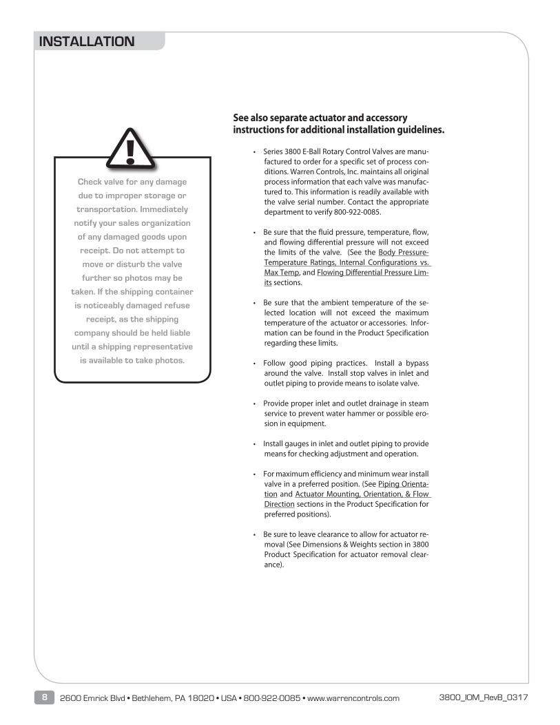
Check valve for any damage
due to improper storage or
transportation. Immediately
notify your sales organization
of any damaged goods upon
receipt. Do not attempt to
move or disturb the valve
further so photos may be
taken. If the shipping container
is noticeably damaged refuse
receipt, as the shipping
company should be held liable
until a shipping representative
is available to take photos.
INSTALLATION
!
9Series 3800 3800_IOM_RevB_0317
• Before installing, be sure valve and piping are clean inside and free of scale, chips, welding spat-ter, and foreign material. Thoroughly blow out or flush pipe lines.
• The valve must be installed with the fluid flowing in the correct direction. For proper operation in all applications, control valves must be piped ac-cording to the corresponding flow arrow present on each valve (See Information Present on Control Valves section for location of important informa-tion on valve). Pipes must be aligned squarely with the valve at each connection.
• Tighten flange bolts evenly to prevent excessive stress and the possibility of uneven sealing.
• The valve, actuator, and accessories (if so equipped) are assembled, tested, and calibrated at the factory. The actuator serial number label specifies set-up parameters used (See Information Present on Control Valves section for location of important information on valve). Do not exceed the supply pressure listed on the serial number label or you will damage the valve and void the warranty.
• Supply air, instrument signal, and accessories should be connected to ports or terminals as indi-cated on the control valve.
• Final tuning may be required under actual operat-ing conditions.
• On critical or dangerous equipment, provide suit-able safety and emergency systems to protect personnel and property from injury due to a valve malfunction. If the valve handles flammable, toxic, corrosive or explosive fluids, provide for safety in the event of valve leakage or malfunction.
• Do not obscure flow arrow plates or serial number labels with paint. If flow arrow plates will be cov-ered with insulation, it is recommended the infor-mation on the plates be transcribed on the outside of the insulation in the same location as the plate.
• Close inlet and outlet stop valves.
• Check that valve responds through rated travel in relation to changes in input signal. Rated travel is shown by position of travel indicator on top of actuator.
• For valves fitted with handwheel, manually operate valve through rated travel to check freedom of movement. Return handwheel to its standby position.
• Place valve in operation.
OPERATION
10 2600 Emrick Blvd • Bethlehem, PA 18020 • USA • 800-922-0085 • www.warrencontrols.com 3800_IOM_RevB_0317
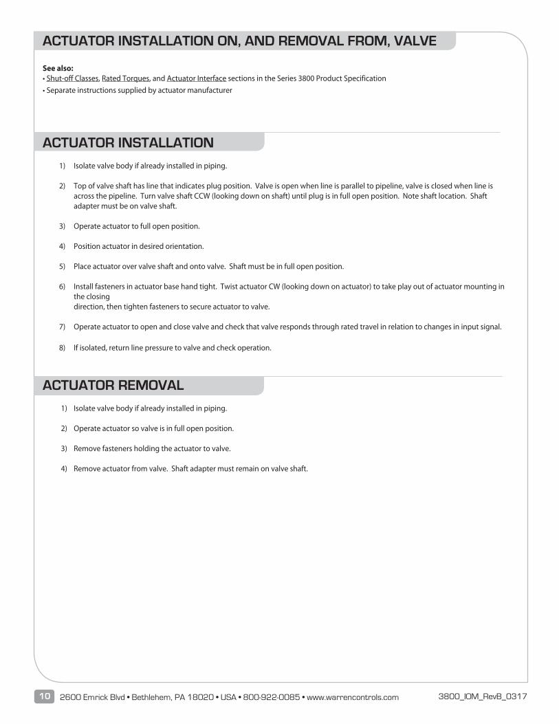
See also: • Shut-off Classes, Rated Torques, and Actuator Interface sections in the Series 3800 Product Specification • Separate instructions supplied by actuator manufacturer
ACTUATOR INSTALLATION
1) Isolate valve body if already installed in piping.
2) Top of valve shaft has line that indicates plug position. Valve is open when line is parallel to pipeline, valve is closed when line is across the pipeline. Turn valve shaft CCW (looking down on shaft) until plug is in full open position. Note shaft location. Shaft adapter must be on valve shaft.
3) Operate actuator to full open position.
4) Position actuator in desired orientation.
5) Place actuator over valve shaft and onto valve. Shaft must be in full open position.
6) Install fasteners in actuator base hand tight. Twist actuator CW (looking down on actuator) to take play out of actuator mounting in the closing
direction, then tighten fasteners to secure actuator to valve.
7) Operate actuator to open and close valve and check that valve responds through rated travel in relation to changes in input signal.
8) If isolated, return line pressure to valve and check operation.
ACTUATOR REMOVAL
1) Isolate valve body if already installed in piping.
2) Operate actuator so valve is in full open position.
3) Remove fasteners holding the actuator to valve.
4) Remove actuator from valve. Shaft adapter must remain on valve shaft.
ACTUATOR INSTALLATION ON, AND REMOVAL FROM, VALVE
11Series 3800 3800_IOM_RevB_0317
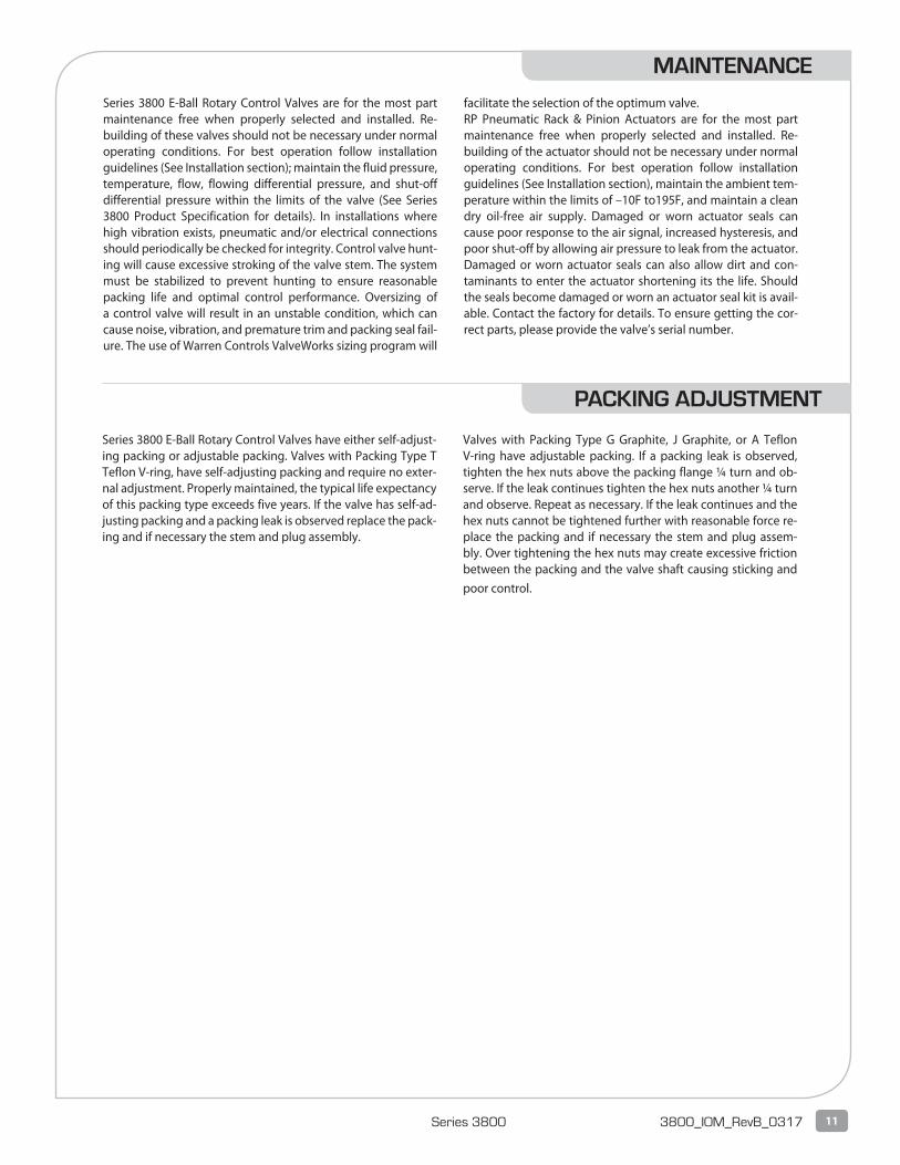
Series 3800 E-Ball Rotary Control Valves are for the most part maintenance free when properly selected and installed. Re-building of these valves should not be necessary under normal operating conditions. For best operation follow installation guidelines (See Installation section); maintain the fluid pressure, temperature, flow, flowing differential pressure, and shut-off differential pressure within the limits of the valve (See Series 3800 Product Specification for details). In installations where high vibration exists, pneumatic and/or electrical connections should periodically be checked for integrity. Control valve hunt-ing will cause excessive stroking of the valve stem. The system must be stabilized to prevent hunting to ensure reasonable packing life and optimal control performance. Oversizing of a control valve will result in an unstable condition, which can cause noise, vibration, and premature trim and packing seal fail-ure. The use of Warren Controls ValveWorks sizing program will
facilitate the selection of the optimum valve. RP Pneumatic Rack & Pinion Actuators are for the most part maintenance free when properly selected and installed. Re-building of the actuator should not be necessary under normal operating conditions. For best operation follow installation guidelines (See Installation section), maintain the ambient tem-perature within the limits of –10F to195F, and maintain a clean dry oil-free air supply. Damaged or worn actuator seals can cause poor response to the air signal, increased hysteresis, and poor shut-off by allowing air pressure to leak from the actuator. Damaged or worn actuator seals can also allow dirt and con-taminants to enter the actuator shortening its the life. Should the seals become damaged or worn an actuator seal kit is avail-able. Contact the factory for details. To ensure getting the cor-rect parts, please provide the valve’s serial number.
Series 3800 E-Ball Rotary Control Valves have either self-adjust-ing packing or adjustable packing. Valves with Packing Type T Teflon V-ring, have self-adjusting packing and require no exter-nal adjustment. Properly maintained, the typical life expectancy of this packing type exceeds five years. If the valve has self-ad-justing packing and a packing leak is observed replace the pack-ing and if necessary the stem and plug assembly.
Valves with Packing Type G Graphite, J Graphite, or A Teflon V-ring have adjustable packing. If a packing leak is observed, tighten the hex nuts above the packing flange ¼ turn and ob-serve. If the leak continues tighten the hex nuts another ¼ turn and observe. Repeat as necessary. If the leak continues and the hex nuts cannot be tightened further with reasonable force re-place the packing and if necessary the stem and plug assem-bly. Over tightening the hex nuts may create excessive friction between the packing and the valve shaft causing sticking and poor control.
MAINTENANCE
PACKING ADJUSTMENT
12 2600 Emrick Blvd • Bethlehem, PA 18020 • USA • 800-922-0085 • www.warrencontrols.com 3800_IOM_RevB_0317
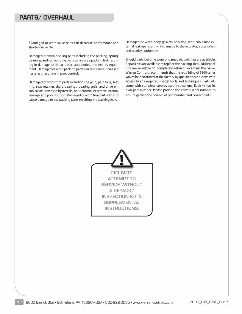
Damaged or worn valve parts can decrease performance and shorten valve life.
Damaged or worn packing parts including the packing, spring, bearings, and surrounding parts can cause a packing leak result-ing in damage to the actuator, accessories, and nearby equip-ment. Damaged or worn packing parts can also cause increased hysteresis resulting in poor control.
Damaged or worn trim parts including the plug, plug face, seat ring, seat retainer, shaft, bearings, bearing seals, and drive pin can cause increased hysteresis, poor control, excessive internal leakage, and poor shut-off. Damaged or worn trim parts can also cause damage to the packing parts resulting in a packing leak.
Damaged or worn body gaskets or o-ring seals can cause ex-ternal leakage resulting in damage to the actuator, accessories, and nearby equipment.
Should parts become worn or damaged, parts kits are available. Repack Kits are available to replace the packing. Rebuild/Repack Kits are available to completely rebuild/ overhaul the valve. Warren Controls recommends that the rebuilding of 3800 series valves be performed at the factory by qualified technicians with access to any required special tools and techniques. Parts kits come with complete step-by-step instructions. Each kit has its own part number. Please provide the valve’s serial number to ensure getting the correct kit part number and correct parts.
PARTS/ OVERHAUL
!DO NOT
ATTEMPT TO SERVICE WITHOUT
A REPACK/INSPECTION KIT & SUPPLEMENTAL INSTRUCTIONS.
13Series 3800 3800_IOM_RevB_0317
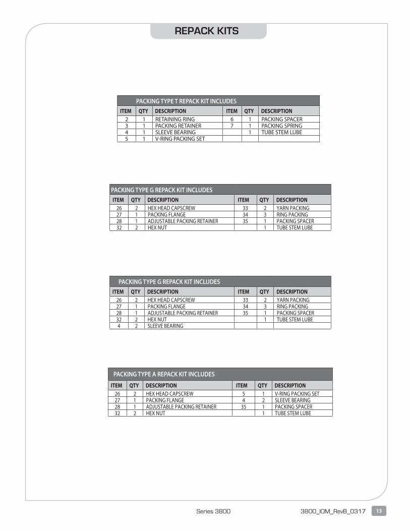
ITEM QTY DESCRIPTION ITEM QTY DESCRIPTION2 1 RETAINING RING 6 1 PACKING SPACER3 1 PACKING RETAINER 7 1 PACKING SPRING4 1 SLEEVE BEARING 1 TUBE STEM LUBE5 1 V-RING PACKING SET
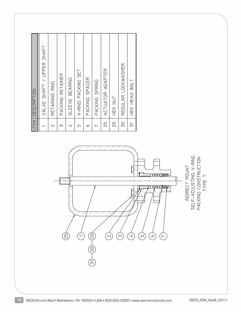
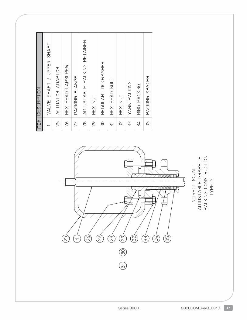
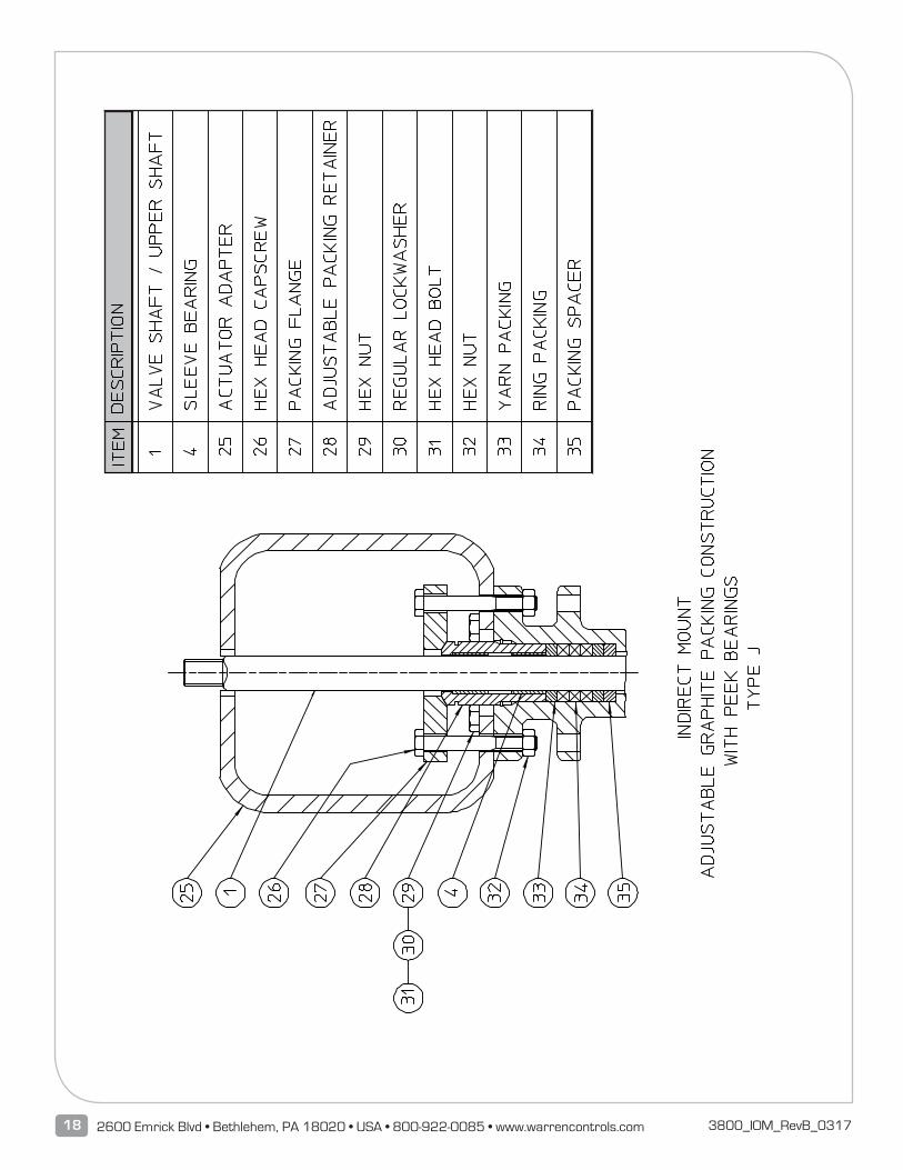
ITEM QTY DESCRIPTION ITEM QTY DESCRIPTION26 2 HEX HEAD CAPSCREW 33 2 YARN PACKING27 1 PACKING FLANGE 34 3 RING PACKING28 1 ADJUSTABLE PACKING RETAINER 35 1 PACKING SPACER32 2 HEX NUT 1 TUBE STEM LUBE
ITEM QTY DESCRIPTION ITEM QTY DESCRIPTION26 2 HEX HEAD CAPSCREW 33 2 YARN PACKING27 1 PACKING FLANGE 34 3 RING PACKING28 1 ADJUSTABLE PACKING RETAINER 35 1 PACKING SPACER32 2 HEX NUT 1 TUBE STEM LUBE4 2 SLEEVE BEARING
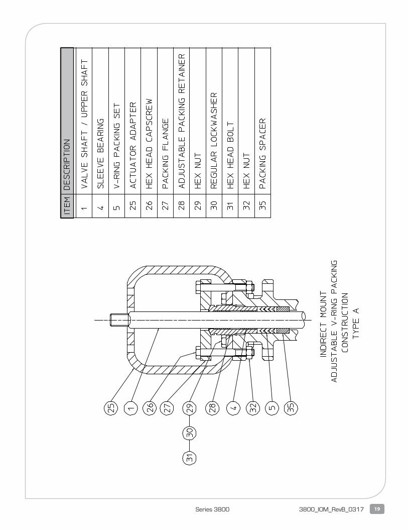
ITEM QTY DESCRIPTION ITEM QTY DESCRIPTION26 2 HEX HEAD CAPSCREW 5 1 V-RING PACKING SET27 1 PACKING FLANGE 4 2 SLEEVE BEARING28 1 ADJUSTABLE PACKING RETAINER 35 1 PACKING SPACER32 2 HEX NUT 1 TUBE STEM LUBE
REPACK KITS
PACKING TYPE T REPACK KIT INCLUDES
PACKING TYPE G REPACK KIT INCLUDES
PACKING TYPE G REPACK KIT INCLUDES
PACKING TYPE A REPACK KIT INCLUDES
14 2600 Emrick Blvd • Bethlehem, PA 18020 • USA • 800-922-0085 • www.warrencontrols.com 3800_IOM_RevB_0317
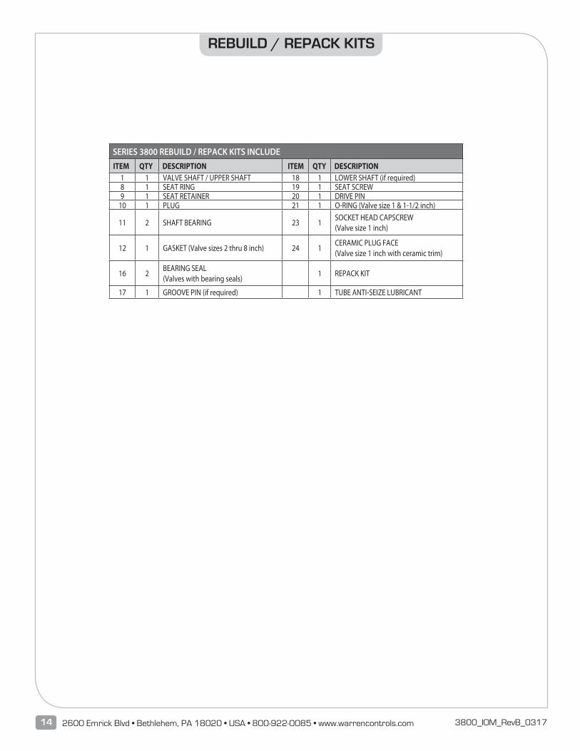
ITEM QTY DESCRIPTION ITEM QTY DESCRIPTION1 1 VALVE SHAFT / UPPER SHAFT 18 1 LOWER SHAFT (if required)8 1 SEAT RING 19 1 SEAT SCREW9 1 SEAT RETAINER 20 1 DRIVE PIN
10 1 PLUG 21 1 O-RING (Valve size 1 & 1-1/2 inch)
11 2 SHAFT BEARING 23 1SOCKET HEAD CAPSCREW(Valve size 1 inch)
12 1 GASKET (Valve sizes 2 thru 8 inch) 24 1CERAMIC PLUG FACE(Valve size 1 inch with ceramic trim)
16 2BEARING SEAL(Valves with bearing seals)
1 REPACK KIT
17 1 GROOVE PIN (if required) 1 TUBE ANTI-SEIZE LUBRICANT
REBUILD / REPACK KITS
SERIES 3800 REBUILD / REPACK KITS INCLUDE
15Series 3800 3800_IOM_RevB_0317
16 2600 Emrick Blvd • Bethlehem, PA 18020 • USA • 800-922-0085 • www.warrencontrols.com 3800_IOM_RevB_0317
17Series 3800 3800_IOM_RevB_0317
18 2600 Emrick Blvd • Bethlehem, PA 18020 • USA • 800-922-0085 • www.warrencontrols.com 3800_IOM_RevB_0317
19Series 3800 3800_IOM_RevB_0317
3800_IOM_RevB_0317
2600 EMRICK BLVD • BETHLEHEM, PA 18020 • USA •800-922-0085 • WWW.WARRENCONTROLS.COMDEPENDABLE, RUGGED, PRECISION CONTROL VALVES AND ACCESSORIES