Embed Size (px)
Citation preview

Installation Instructions
Renovent Excellent 400 (Plus)


Heat recovery appliance Renovent Excellent 400 (Plus)
STORE NEAR THE APPLIANCE
Country : UK
Installation instructions
Use of this appliance is not permitted for persons, including children, with limited intellectual abilities, serious physical limitations or lack of experience and knowledge, unless they are supervised by, or have received instructions of how to use the appliance from, a person who is responsible for their safety.
Children must be supervised to ensure that they do not play with the appliance.

Renovent Excellent 1st edition February 2011
Table of contents
11.11.2
2
33.13.23.33.43.4.13.4.2
44.14.24.34.4
55.15.25.35.45.55.5.15.5.25.5.3
66.16.26.2.16.2.26.2.36.36.46.5
77.17.27.37.4
88.18.2
Delivery..........................................................Scope of delivery............................................Accessories Renovent Excellent ....................
Application ....................................................
Version...........................................................Technical information......................................Fan graph .......................................................Exploded view appliance................................Connections and dimensions .........................Renovent Excellent right-handed version......Renovent Excellent left-handed version........
Operation.......................................................Description......................................................Bypass conditions...........................................Frost safety.....................................................Renovent Excellent Plus.................................
Installation.....................................................Installation general .........................................Placing the appliance .....................................Connecting the condensate discharge ...........Connecting ducts............................................Electric connections........................................Connection of the power plug........................Connecting the multiple switch......................Connection eBus or OpenTherm connector ..
Display...........................................................General explanation control panel..................Operating mode.............................................. Status system fan..........................................
.......................................Message text for operating mode...................Settings menu.................................................Readout menu................................................Service menu..................................................
Putting into operation ..................................Switching the appliance on and off.................Setting the air quantity....................................Other settings installer....................................Factory setting................................................
Fault ...............................................................Trouble shooting.............................................Display codes .................................................
112
4
5567889
1010101010
111111111113131313
141415151516171819
2020212121
222222
99.19.2
1010.110.2
1111.111.211.2.111.2.2
11.2.3
11.2.4
11.3
11.3.1
11.3.2
11.4
11.5
11.6
11.7
1212.112.2
13
Maintenance................................................Filter cleaning ..............................................Maintenance.................................................
Electric diagrams........................................Basic diagram...............................................Wiring diagram .............................................
Electric connections accessories.............Connections connectors...............................Connection examples multiple switch...........
...............
indication) .....................................................-
tion................................................................Additional multiple switch wireless remote control...........................................................Coupling several Renovent Excellent appli-ances............................................................
individually adjustable ..................................Coupling through eBus; all appliances equal
...................................................Wiring diagram postheater connection (only for Renovent Excellent Plus) ........................Connection example geo heat exchanger (only possible for the Renovent ExcellentPlus) .............................................................Connecting external switch contact (only possible for Renovent Excellent Plus) ..........Connection to 0-10 V input (only possible for Renovent Excellent Plus) .............................
Service.........................................................Exploded view ..............................................Service articles .............................................
Setting values .............................................
Declaration of conformity..............................
242425
272728
29293030
30
30
30
31
31
31
32
33
34
35
363637
38
40

Renovent Excellent 1st edition February 2011 1
Delivery Chapter 1
Before starting installation of the heat recovery unit, check that it has been supplied complete and undamaged.
The scope of delivery of the heat recovery unit Renovent Excellent includes the following components:
Heat recovery appliance type Renovent Excellent
Wall mounting bracket kit containing: • 2 x suspension strips • 3x protective caps • 1 x rubber strip • 2 x rubber rings • 1 x mounting instructions
PVC condensate discharge connection containing: • 1 x synthetic screw gland 1.5” • 1 x sealing ring • 1 x PVC glued coupling 32 mm
Documentation set consisting: • 1 x installation instructions • 1 x occupants instructions
4
6305-A
1.1 Scope of delivery

2 Renovent Excellent 1st edition February 2011
Chapter 1 Delivery
1.2 Accessories Renovent Excellent
Article description Article code
Synthetic duct Ø180 mm / Length 2250 mm (box of 4) 200131
Synthetic bend 90° Ø180 mm (box of 8) 200132
Synthetic bend 45° Ø180 mm (box of 8) 200133
Synthetic bend 30° Ø180 mm (box of 8) 200134
Synthetic bend 15° Ø180 mm (box of 8) 200135
Synthetic coupler Ø180 mm (box of 1) 200138
Acoustic duct Ø180 mm / Length 10 m 207780
Acoustic duct Ø180 mm / Finished length 1.5 m (1) 207782
Mounting support Excellent 400 217035
Electric postheater 310650
6308-A
6322-A

Renovent Excellent 1st edition February 2011 3
Delivery Chapter 1
Article description Article code
Splitter RJ12 510453
CO2 sensor surface-mounted 511348
Transmitter wireless remote control 2 positions (with. battery) 531785
Transmitter wireless remote control 4 positions (with. battery) 531786
Receiver wireless remote control (for battery version) 531787
Kit wireless remote control 2 positions (1 transmitter & 1 receiver) 531788
Kit wireless remote control 4 positions (1 transmitter & 1 receiver) 531789
Delivered with insert plate and cover frame 540214
modular connection. Delivered with insert plate and cover frame 540215
Connecting kit Ø180 mm (2 x acoustic duct 1.5 m long with 648570
Ventilation roof sleeve D180 (suitable for supply, under the tiles ; insulated) 648680
Ventilation sleeve exterior wall D180 (suitable for supply,insulated) 648690
Ventilation roof sleeve D166 (suitable for extract; insulated) 648700
6323-A
6324-A

4 Renovent Excellent 1st edition February 2011
The Brink Renovent Excellent is a ventilation unit with heat -
pacity of 400 m3/h and low-energy fans. Features RenoventExcellent:
indication on the multiple switch; • a completely new intelligent frost protection system which
ensures that also at low outdoor temperatures the applian-ce's performance remains optimal and that, if necessary, it activates the standard preheater.
• low sound level • comes as standard with automatic bypass valve
• low energy consumption
Renovent Excellent 400 is available in two types:• Renovent Excellent”• Renovent Excellent Plus”
Compared to the Renovent Excellent, the Renovent ExcellentPlus has a more extensive control board which increases the connection options.
These installation instruction describe both the standard Reno-vent Excellent and the Renovent Excellent Plus.The Renovent Excellent (Plus) is available in the left-handed
air ducts differs for these two versions! For the correct position of the connection ducts and dimensions see §3.4.1 or §3.4.2. respectively.
When ordering an appliance always state the correct type; sub-sequent conversion to a different version is not possible.
The Renovent Excellent comes ready to plug in with a 230 V mains plug and a connection for a low-voltage multiple switch on the outside of the appliance.
Note: When replacing a Renovent Large by a RenoventExcellent, do realise that the positions of the ducts “From dwelling” and “From atmosphere” are diffe-rent! (only for type 4/0 & 3/1) Carefully check the po-sition of these ducts on the basis of the connection drawings §3.4.1 and §3.4.2.
Version types Renovent Excellent 400
Type Version L of R Position air ducts Power supply Type code
Renovent Excellent
Left-handed version
4 top connections Power plug 4/0 L
2 top connections & 2 bottom connections Power plug 2/2 L
3 top connections & 1 bottom connection Power plug 3/1 L
Right-hand version
4 top connections Power plug 4/0 R
2 top connections & 2 bottom connections Power plug 2/2 R
3 top connections & 1 bottom connection Power plug 3/1 R
Renovent Excellent Plus
Left-handed version
4 top connections Power plug 4/0 L+
2 top connections & 2 bottom connections Power plug 2/2 L+
3 top connections & 1 bottom connection Power plug 3/1 L+
Right-hand version
4 top connections Power plug 4/0 R+
2 top connections & 2 bottom connections Power plug 2/2 R+
3 top connections & 1 bottom connection Power plug 3/1 R+
Chapter 2 Application

Renovent Excellent 1st edition February 2011 5
Version Chapter 3
3.1 Technical information
Renovent Excellent 400
Supply voltage [V/Hz] 230/50
Protection degree IP30
Dimensions (w x h x d) [mm] 675 x 765 x 564
Duct diameter [mm] Ø180
External diameter condensate discharge [mm] Ø32
Weight [kg] 38
Filter class G3 (F7 optional for supply)
Fan setting (factory setting) 1 2 3
Ventilation capacity [m3/h] 100 200 300
Permissible resistance ducts system [Pa] 6 - 20 25 - 49 56 - 178
Rated power (excl. preheater)[W] 9.5 - 15 29 - 40 72 - 98
Rated current (excl. preheater)[AA] 0.12 - 0.14 0.24 - 0.31 0.51 - 0.7
Max. rated current (with preheater switched on) [A] 6
0.45 - 0.40 0.56 - 0.58 0.60 - 0.61
Sound power Excellent 400Ventilation capacity [m3/h] 100 200 225 300 400Sound power level Lw (A)
Static pressure [Pa] 9 40 38 80 47 100 84 175 240 150 225Housing emission [dB(A) 28.5 31.5 39.5 40.5 42.5 46.5 52.0 50.0 53.0 53.5 56.0Duct “from dwelling” [dB(A)] 30.5 33.5 45.5 47.0 47.5 49.0 55.5 56.0 57.0 58.0 59.0Duct “to dwelling” [dB(A)] 41.5 46.5 56.0 58.0 59.5 61.5 65.0 67.5 68.5 69.5 70.5
In practice, the value may deviate 1 dB(A) as a result of measuring tolerances
Ventilation capacity [m3/h] 100 200 225 300 400Sound pressure level Static pressure [Pa] 9 40 38 80 47 100 84 175 240 150 225
Duct “from dwelling” [dB(A)] 0.1 0 12.2 13.3 13.8 14.0 20.4 19.7 20.6 22.8 23.4Duct “to dwelling” [dB(A)] 8.1 12.5 20.5 22.2 23.6 25.1 28.5 30.6 30.9 33.0 34.1
Ventilation capacity [m3/h] 100 200 225 300 400Sound pressure level Static pressure [Pa] 9 40 38 80 47 100 84 175 240 150 225
Duct “from dwelling” [dB(A)] -6.6 -4.0 8.3 9.7 10.3 10.8 16.9 16.7 17.5 19.9 20.8Duct “to dwelling” [dB(A)] 3.5 8.2 17.4 19.4 20.7 22.5 25.8 27.8 28.3 30.4 31.7

6 Renovent Excellent 1st edition February 2011
Chapter 3 Version
3.2 Fan graph
Fan graph Renovent Excellent 400 6262-B
Note: The value stated in the circle is the capacity per fan (in Watt)
Flow rate [m3/h]
Resis
tanc
educ
tssy
stem
[Pa]
0
25
50
75
100
125
150
175
200
225
250
275
300
325
350
375
400
0 25 50 75 100 125 150 175 200 225 250 275 300 325 350 375 400 425
79
86
83
7158
51
49
40
36
32
28
23
20
17
157 10
12
5
26
22
19

Renovent Excellent 1st edition February 2011 7
Version Chapter 3
6263-C
1 Service connector Computer connection for service purposes.
2 Display and 4 control buttons Interface between user and control electronics.
3 Control board Contains the control electronics for the basic functions.
4
5 Preheater Heats up the outdoor air when there is a risk of freezing for the heat exchanger
6 Heat exchanger Ensures heat transfer between input and output air
7 Filters outdoor are supplied to the dwelling
8 Outdoor temperature sensor Measures outside air temperature.
9 Indoor temperature sensor Measures the dwelling air temperature
10 Bypass valve Sends the air through or around the heat exchanger (For the 3/1 and 4/0 this valve is in the upper part of the appliance)
11 Condensate discharge Connection condensate discharge (Kit comes separately with the appliance)
12 Extract fan Discharges air from the dwelling to the atmosphere.
13 Supply fan Feeds fresh air into the dwelling.
14 Modular connector multiple switch X2
15 Connector eBus X1 Connection for eBus control
16 Connector X15 Contains the various control inputs and outputs; only for Plus version
17 Connector X14 Connection postheater; only for Plus version (accessible after taking off the display cover)
18 Mains cable 230 V Gland power cable 230 volt
19 Connection to postheater Gland 230 V cable to postheater; only for Plus version
Rear view display cover
3.3 Exploded view appliance

8 Renovent Excellent 1st edition February 2011
Chapter 3 Version
6266-BRenovent Excellent Right-handed 2/2 6267-BRenovent Excellent Right-handed 4/0
6268-BRenovent Excellent Right-handed 3/1
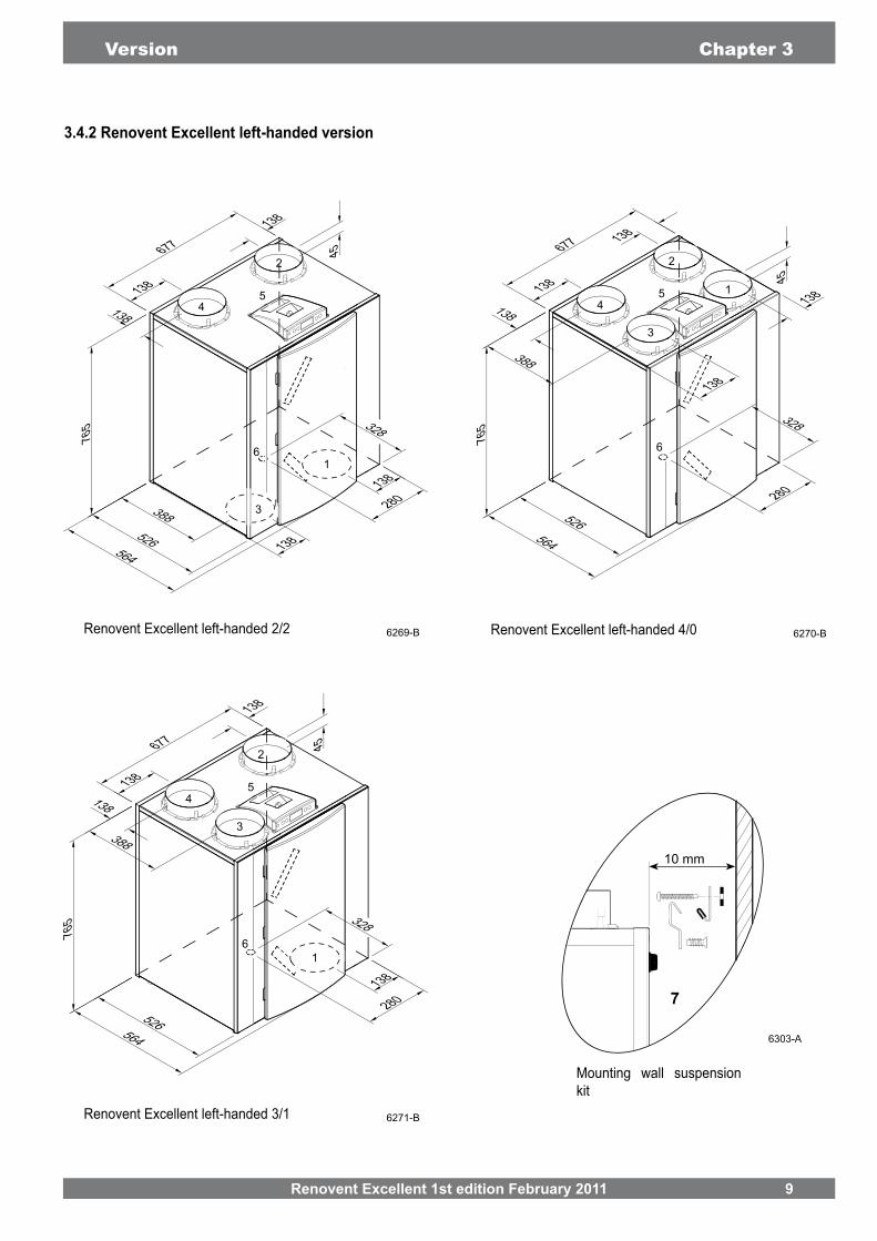
1 = To dwelling
2 = To atmosphere
3 = From dwelling
4 = From atmosphere
5 = Electric connections
6 = Connection condensate discharge
7 = Wall mounting bracket (note the correct position of the rubber strip, washers and caps)
Renovent Excellent 1st edition February 2011 9
6269-BRenovent Excellent left-handed 2/2 6270-BRenovent Excellent left-handed 4/0
6271-BRenovent Excellent left-handed 3/1
Version Chapter 3
7
10 mm
Mounting wall suspension kit
6303-A
10 Renovent Excellent 1st edition February 2011
Chapter 4 Operation
4.2 Bypass conditionsThe standard bypass valve makes it possible to supply fresh outside air that is not heated by the heat exchanger. Particular-ly during summer nights it is desirable to supply cooler outside air. Then the hot air in the dwelling is replaced by cooler outside air in so far as possible.
The bypass valve opens and closes automatically when a num--
pass conditions).The operation of the bypass valve can be adjusted in step num-ber 4 and step number 5 in the settings menu (see chapter 13).
4.3 Frost protectionTo prevent freezing of the heat exchanger at extremely low out-door temperatures, the Renovent Excellent features intelligent frost control. Temperature sensors measure the temperatures
across the heat exchanger and, if necessary, the preheater is switched on. That guarantees a proper ventilation balance, also at very low outdoor temperatures.
Bypass valve conditions
Bypass valve open - The outdoor temperature is higher than 10°C and- the outdoor temperature is lower than the indoor temperature in the dwelling and- the temperature in the dwelling is higher than the temperature set at step no. 4 in the set-
tings menu (set a standard at 22°C).
Bypass valve closed - The outdoor temperature is lower than 10°C or- the outdoor temperature is 0.5°C higher than de indoor temperature in the dwelling or- the temperature from the dwelling is higher than the temperature set at step no. 4 in the
settings menu (set a standard at 22°C).
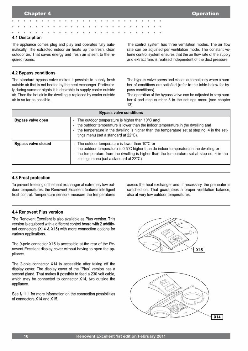
4.4 Renovent Plus versionThe Renovent Excellent is also available as Plus version. Thisversion is equipped with a different control board with 2 additio-nal connectors (X14 & X15) with more connection options for various applications.
The 9-pole connector X15 is accessible at the rear of the Re-novent Excellent display cover without having to open the ap-pliance.
The 2-pole connector X14 is accessible after taking off the display cover. The display cover of the “Plus” version has a second gland. That makes it possible to feed a 230 volt cable, which may be connected to connector X14, two outside the appliance.
See § 11.1 for more information on the connection possibilities of connectors X14 and X15.
4.1 DescriptionThe appliance comes plug and play and operates fully auto-matically. The extracted indoor air heats up the fresh, clean outdoor air. That saves energy and fresh air is sent to the re-quired rooms.
rate can be adjusted per ventilation mode. The constant vo-
and extract fans is realised independent of the duct pressure.
X14
X15

Renovent Excellent 1st edition February 2011 11
Installation Chapter 5
5.1 Installation generalInstalling the appliance1. Placing the appliance (§5.2)2. Connecting the condensate discharge (§5.3)3. Connecting the ducts (§5.4)4. Electric connection Connecting the mains power, multiple switch and, if neces-
sary, the OpenTherm/eBus coupler (§5.5)
Installation must take place under:
• Quality requirements ventilation systems dwellings. • Quality requirements balanced ventilation in dwellings.• The regulations for ventilation of dwellings and residential
buildings.• The safety regulations for low-voltage installations. • The regulations for connection to interior sewers in dwel-
lings and residential buildings. • Any additional regulations of the local utilities.• The installation instructions for the Renovent Excellent.
5.2 Placing the applianceThe Renovent Excellent can directly be mounted to the wall using the suspension brackets supplied for that purpose. For a vibration-free result the appliance must be mounted to a solid wall with a minimum mass of 200 kg/m2. A gypsum block or
double panelling or extra studs are required in that case. On
addition, the following aspects must be taken into account.• The appliance must be placed level.
• The installation room must be such that a good conden-sate discharge with air trap and pitch for condensate can be made.
• The installation room must be frost-free.• Make sure there is a free space of at least 70 cm at the
front of the appliance and a free headroom of 1.8 m for
• Make sure there is a free space of at least 20 cm above the display cover so it can always be removed.
To prevent condensation on the outside of the outdoor air sup-ply duct and the air extract duct from the Renovent Excellent,these ducts must be provided with an external vapour barrier as far as the appliance. If Brink synthetic (EPE) pipe is used here, additional insulation is not necessary.
For optimum fan noise damping, it is recommended to use
appliance and the ducts from and to the dwelling.
Pay attention to crosstalk and installation noise, also for incor-porated ducts. Design the duct with separate branches to the valves to prevent crosstalk. If necessary, the supply ducts must be insulated, for instance when they are installed outside the insulated envelope. Preferably use Brink incorporated ducts. These ducts have been developed with a view to a low duct resistance. A duct diameter of 180 mm is required for the Renovent Excel-lent.
The condensate discharge line for the Brink Renovent HR is fed through the lower panel. The condensate must be discharged through a drainpipe.
The condensate discharge comes separately with the applian-ce and the installer must screw it into the underside of the ap-pliance. This condensate discharge connection has an external connecting diameter of 32 mm.
The condensate discharge line can be glued to it, if necessary using a square bend. The installer can glue the condensate discharge in the desired position in the lower part of the ap-pliance. The drain must discharge under the water level in the U-trapBefore connecting the condensate discharge to the appliance, pour water into the U-trap to create an air trap.
6264-A
Glued connection;Ø32 mm
Screw connection

12 Renovent Excellent 1st edition February 2011
Chapter 5 Installation
• Arrange the exterior air supply from the shadowed side of the dwelling, preferably from the wall or overhang. If the out-door air is sucked in from under the tiles, it must be ensured that no condensation develops in the roof boarding and no water can run in. Ventilation air can be sucked in from under the tiles if air can access freely at the top and the bottom of the roof area and the sewage vent stack does not end under the tiles.
• Feed the extract duct through the roof boarding in such a manner that no condensation develops in the roof boar-ding.
• Install the extract duct between the Renovent Excellent and the roof sleeve in such a manner that surface condensation is prevented.
• Always use an insulated ventilation roof sleeve.
• The maximum permissible resistance in the duct system is 150 Pa at the maximum ventilation capacity. If the resi-stance of the duct system is higher, the maximum ventilation capacity will be lower.
• The location of the mechanical ventilation output and the sewer stack vent relative must be chosen to prevent nuisan-ce.
• Choose the location of the supply valves to prevent fouling and draught. We recommend to use the Brink supply val-ves.
1 = Renovent Excellent left-handed 2/2 (place level)
2 = Preferred ventilation air supply3 = Ventilation air supply under the
tiles4a = Free suction bottom roof area4b = Free suction top roof area5 = Sewer vent6 = Preferred location extract ven-
tilation air; use Brink insulated ventilation roof sleeve.
heat recovery duct8 = Condensate discharge9 = Acoustic duct10 = Ducts from and to dwelling
6265/B
A = Spacing 10 mm above roof deckB = Roof insulationC = Seal with foamD = Pipe for make-up air to be carefully insulated and provi-
ded with vapour barrier
1 = Brink supply valves2 = Supply from wall3 = Suction valve in ceiling or high in wall4 = Prevent crosstalk5 = Preferably Brink incorporated ducts
a = Gap under the door 2 cm.
4761A
4759-0

Renovent Excellent 1st edition February 2011 13
Installation Chapter 5
5.5 Electric connections
The multiple switch (not supplied with the appliance) is connec-ted to the modular connector type RJ12 (connector X2) that is placed at the rear of the appliance's display cover.
Dependent on the type of multiple switch that is used, a plug RJ11 or RJ12 can be connected to it.
-ses requires an RJ12 plug in combination with a 6-core modular cable.
cases requires an RJ11 plug in combination with a 4-core modular cable.
Refer to diagrams §11.2.1 to §11.2.4 for connection examples multiple switch.
Other options include wireless remote control or a combination of multiple switches.
The appliance can be connected to an easily accessible, earthed wall socket with the plug that is mounted to the ap-pliance. The electric installation must comply with the require-ments of your power company.
Make allowance for the 1000 W preheater.
WarningThe fans and control board carry a high volta-ge. Always take the voltage from the appliance by pulling the power plug when working on the appliance.
The Renovent Excellent can operate with Opentherm as well as with eBus protocol. The setting of parameter 06 in the set-tings menu (see chapter 13) lets you choose between eBus and OpenTherm.An eBus or OpenTherm connection can be made with the 2-pole connector X1 at the rear of the display cover.
The eBus protocol can for instance be used for coupling (cas-cade control) appliances (see §11.3.2). Because of polarity sensitivity, always connect contacts X1-1 to X1-1 and contacts X1-2 to X1-2 ; the appliance will not work when these contacts are interchanged!
For the OpenTherm protocol interchanging the cable connec-
appliance's performance.
RJ12
6310-A
6311-A
X1

14 Renovent Excellent 1st edition February 2011
6.1 General explanation control panelThe LCD display shows what the operating situation of the ap-pliance is. Four control keys can be used to call up and modify settings in the control unit program.When the mains power to the Renovent Excellent is switched on, all display symbols will appear during 2 seconds; at the same time the blue backlight is switched on for 60 seconds..When one of the control keys is operated, the display will light up during 30 seconds.
When no keys are operated or when no deviating situation has developed (such as a blocking fault) the display will show the operating mode (see § 6.2).
After operating the key ‘Menu’, the keys “+” or “-” can be used to select from three different menus, including:
• Settings menu (SET); see § 6.3• Readout menu (READ), see § 6.4• Service menu (SERV), see § 6.5
Press the R key to leave any menu and return to operating mode.
the display backlight without changing anything in the menu.
.
Key Function key
Menu
- Scroll; modify value; Switching on or off the Renovent Excellent from operating mode (the press for 5 seconds)
+ Scroll; modify value
R
Chapter 6 Display image
6134-A
A = LCDB = 4 control keysC = service connector
A
B
C

Renovent Excellent 1st edition February 2011 15
6.2 Operating modeIn operating mode the display may simultaneously show 4 dif-ferent situations/values.
1 = Status fan situation, image coupled appliances (see§ 6.2.1)
(see § 6.2.2)
3 = Message text -nal switch contact etc. (see § 6.2.3)
4 = Fault symbol (see § 8.1 and § 8.2)
differ, for instance when using an external switch contact, in all
When the appliance is switched off through software, the text “OFF” appears here.
This part of the display shows a fan together with a number. When the supply and extract fans are running, the fan symbol is displayed. When the fans are stopped, the fan symbol is not visible.The number behind the fan symbol indicates the fan situation. Refer to the table below for an explanation of the numbers.
Status fansituation on display Description
1 The supply and extract fans are running under mode 1 of the multiple switch.
2 The supply and extract fans are running under mode 2 of the multiple switch.
3 The supply and extract fans are running under mode 3 of the multiple switch.
This Renovent Excellent is coupled with the aid of eBus or OpenTherm connection The supply and extract fans of the Renovent Excellent are running under switched mode of the ventila-tion mode “master” Renovent; in addition, (only for cascade connection) the display shows the “slave” number of the relevant Renovent.
6245-B
Display Chapter 6
6.2.1 Status system fan

16 Renovent Excellent 1st edition February 2011
This part of the display may show a message text. The mes-sage text “Filter” always takes precedence over the other mes-sage texts.
The following message text may appear during operating mode.
6250-A
Chapter 6 Display
Slave - appliance
Master - appliance
6.2.3 Message text for operating mode
6248-A
6245-B
Message texton display
Description
FILTER When the text “FILTER” ap-
must be cleaned or replaced; for detailed information, see § 9.1
Slave 1, Slave 2 etc.
For coupled appliances the message text shelves which appliances “Slave 1” - “Slave 9”; for detailed information, see §11.3.2.The “Master” appliance dis-plays the regular image regar-ding ventilation mode.
EWT
(only for Plusversion)
When the text “EWT” appears on the display, the geo heat exchanger is active.For extensive information, also see §11.5.
CN1 or CN2
(only for Plusversion)
When the text “CN1 or CN2”appears on the display, one of the external switch inputs is active, also see §11.6.
V1 or V2
(only for Plusversion)
When the text “CN1 or CN2”appears on the display, one of the external 0 - 10 V inputs is active, also see §11.7.

Renovent Excellent 1st edition February 2011 17
6.3 Settings menuFor optimum performance of the appliance, set values can be
installation situation; refer to chapter 13 for a list of the set va-
down in the design data.
Modifying the set value in the settings menu:
1. In operating mode, press the ‘MENU’ key.
2. Press the ‘Menu’ key to activate the “settings menu”.
4 Press the ‘Menu” key to select the required set value.
5 Use keys ‘ ‘ and ‘+’ key to modify selected set value.
6 Store
Do not store
7 To modify other set values, repeat step 3 - 6. When you do not want to modify any more set values and return to operating situation, then press the ‘R’ key.
Warning:Because changes may affect the proper performance of the appliance, changes of settings not described here require consultation with Brink.Incorrect settings may seriously affect the proper perfor-mance of the appliance!
Warning:Because changes may affect the proper performance of the appliance, changes of settings not described here require consultation with Brink.Incorrect settings may seriously affect the proper perfor-mance of the appliance!
1 x
1 x
Display Chapter 6
Do not storesettings menu is active
6251-B
Back to operating mode
1 x
.
Step number setting value
Setting value
1 x
1 x

18 Renovent Excellent 1st edition February 2011
The readout menu can be used to call up a number of current sensor values to obtain more information on the appliance's performance. Modifying values of set-tings is not possible in the readout menu. The readoutmenu can be displayed as follows.
1. In operating mode, press the ‘MENU’ key. Now the display shows the settings menu.
2. Use the ‘+’ and the ‘ ’ key to go to the readout menu.
3. Activate the readout menu.
4 Use the ‘+’ and the ‘ ’ key to scroll through the rear menu.
5 Press the ‘R’ key twice to go back to operating mode. If no key is operated during 5 minutes, the appliance auto-
matically returns to operating mode.
6.4 Readout menu
Step no. readoutvalue Description readout value Unit
01 Current temperature from dwelling °C
02 Current temperature outdoors sensor oC
03 Bypass status (ON = bypass valve open, OFF = bypass valve closed)
04 Status frost protection (ON = frost protection active, OFF = frost protection not active)
05 Current channel pressure supply Pa
06 Current duct pressure extract Pa
07 m3/h
08 m3/h
6253-A
readout value
Step no. readout value;refer to the table below for an explanation
2 x
Chapter 6 Display
readout menu
settings menu
operating mode
operating mode

Renovent Excellent 1st edition February 2011 19
The service menu shows the most recent 10 fault messages.
In the event of a locking fault, the settings menu and the readout menu are blocked and only the service menu can be opened; Pressing the ‘menu’ key directly opens the service menu.
The service menu can be displayed as follows.
1. In operating mode, press the ‘MENU’- key. The display now shows the settings menu.
2. Use the ‘+’ and the ‘-’- ’ key to go to the service menu.
3. Activate the service menu.
4 Use the ‘+’ and the ‘ ’ key to scroll through the messages in the service menu.
- Display not any fault message.
- Current fault message (spanner on display).
- Unsolved fault message (no spanner on display).
5 Press the ‘R’ key twice to go back to operating mode. If no key is operated during 5 minutes, the appliance auto-
matically returns to operating mode.
All fault messages can be deleted by pressing the “R” key in the service menu during 5 seconds; This is only possible when there is no active fault!
Display Chapter 6
6.5 Service menu
6252-A
No. fault message
settings menu
operating mode
service menu
operating mode
2 x
Fault code; refer to § 8.1 and§ 8.2 for explanation fault code

20 Renovent Excellent 1st edition February 2011
Switching off:• Switching off through software
Press the “ ” key for 5 sec. to switch off the appliance through software. The text 'OFF' appears on the display.
• Switching off the mains power ; Pull the 230 V mains plug from the mains to take the voltage
from the appliance. Nothing is shown on the display now.
Switching on• Switching on the mains power. Connect the 230 V power plug to the electric system.
All display symbols appear during 2 seconds.
The software version appears during 2 seconds.
Directly after that the Renovent Excellent will be running in the mode is set on the multiple switch. If no multiple switch is connected, the appliance will always run in mode 1.
• Switching on through softwareWhen the Renovent Excellent switched off through software, the display will show the text “OFF”.
The appliance can be switched on by pressing the key ‘-’ during 5 seconds.
Chapter 7 Putting into operation
7.1 Switching the appliance on and off
WarningWhen working on the appliance, always take
it off through software and subsequently pulling the power plug.
2 sec.
2 sec.
> 5 sec.
6258-A
>5 sec.
There are two methods to switch the appliance on or off.
- Switching on and off by inserting or pulling the power plug.- Switching on and off through software on the appliance display.

Renovent Excellent 1st edition February 2011 21
-tes set for modes 1, 2 and 3 for 100, 200 and 300 m3/hrespectively. The performance and the energy consump-tion of the Renovent Excellent depend on the pressure
Important:Mode 1: must always be lower than mode 2.Mode 2: must always be lower than mode 3;Mode 3: adjustable between 50 and 400 m3/h;
higher mode will automatically be adjusted.
-des 1, 2 and 3.
Putting into operation Chapter 7
7.4 Factory setting-
ting in one go.
Renovent Excellent was supplied from the factory; all message codes / fault codes will be erased from the service menu as well.
6259-A
7.3 Other settings installerVarious other settings of the Renovent Excellent can also be
operating mode
3 sec. visible
press > 10 sec. simultaneously

22 Renovent Excellent 1st edition February 2011
Chapter 8 Fault
8.1 Trouble shootingWhen the appliance control system detects a fault, it is indi-cated on the display with a spanner symbol, possibly together with a fault code.
The appliance makes a distinction between a fault at which the appliance keeps running (limitedly) and a serious (locking) fault at which both fans are switched off.
In case of locking fault, the settings and readings menu is swit-ched off as well and only the service menu is available.
The appliance remains in this fault mode until the problem in question has been solved. Then the appliance will reset itself (auto reset) and the display will once more show the operatio-nal mode.
The fans are controlled on the basis of the value of the pressure sensors mounted on the control board. For each fan 2 pressure hoses run to the control board. If these hoses are not connec-ted as prescribed, or if they are leaking or blocked, a wrong pressure will be measured so the fans can no longer be con-trolled correctly. In case of doubt on the correct performance of the appliance, check the pressure hose connections.
6245-B
6261-A
Fault E999If, when the appliance is powered up directly to message E999appears on the display, the mounted control board is not sui-table for this appliance or the dip switches on the control board are set incorrectly .For the location of the dip switches see § 10.2; position M
In that case, check whether the dip switches on the control board are set as shown in the drawing of the dip switches set-tings; if they are, and the message E999 still appears, then replace the control board by a board of the correct type.
Settings dip switches Renovent Excellent
Settings dip switchesRenovent Excellent Plus
When the appliance detects a locking fault, it will no longer work. The (permanently lighted) display shows the fault symbol (spanner) together with fault code. The red LED on the multiple switch (if applicable) will be blinking. Contact the installer to remedy this fault. A locking fault cannot be remedied by taking
6248-A
8.2 Display codes
When the appliance detects a non-locking fault, it will still keep running (limitedly). The display does show the fault symbol (spanner).

Renovent Excellent 1st edition February 2011 23
Fault Chapter 8
Faultcode Action appliance Action installer
E100Pressure sensor supply fan defective.Red pressure hoses blocked or “kinked”
- Switches to constant rpm control.- The preheater switches on at outdoor
temperatures below 0°C.
• Take the voltage from the appliance. • Replace the supply fan pressure
sensor• Check the red pressure hoses (and
pressure tubes) for fouling, kinking and damage
E101Pressure sensor extract fan defective.Blue pressure hoses blocked or “kinked”
- Switches to constant rpm control.- The preheater switches on at outdoor
temperatures below 0°C
• Take the voltage from the appliance.• Replace extract fan pressure sensor • Check blue pressure hoses (and
pressure tubes) for fouling, kinking and damage
E103Bypass fault .
- None.
correctly connected or effective;
wiring or stepper motor)
• Take the voltage from the appliance.• Check connection stepper motor;
replace wiring or stepper motor
E104Extract fan defective.
- Both fans are switched off. - Preheater is switched off.- If applicable: Postheater is switched off.- Restart every 5 minutes.
• Take the voltage from the appliance.• Replace extract fan.• But voltage back on appliance; Fault
will automatically be reset.• Check cabling.
E105Supply fan defective.
- Both fans are switched off.- Preheater is switched off.- If applicable: Postheater is switched off.- Restart every 5 minutes.
• Take the voltage from the appliance.• Replace• Put voltage back on appliance; Fault
will automatically be reset.• Check cabling.
E106 The temperature sensor that measures the outdoor tempe-rature is defective. .
- Both fans are switched off.- Preheater is switched off.- Bypass closes and is blocked.
• Take the voltage from the appliance.• Replace temperature sensor • Put voltage back on appliance; fault
will automatically be reset.
E107 The temperature sensor that measures the temperature of the extract air is defective..
- Bypass closes and is blocked.• Take the voltage from the appliance.• Replace indoor temperature
sensor
E108 If present: The temperature sensor that measures the ex-ternal temperature is defective.
- Postheater is switched off.- If applicable: Geo heat exchanger is
switched off.
• Replace external temperature sensor
E999 Dip switches on control board not set correctly.
- Appliance does nothing; red fault LEDon multiple switch is not activated either.
• Put dip switches incorrect position. (see § 8.1).
Note!If mode 2 of a multiple switch does not work, the modular connector of the multiple switch has been connected the wrong way round.Cut off one of the RJ connectors to the multiple switch and mount a new connector the other way round.
(locking fault)
(non-locking fault)
(non-locking fault)
(non-locking fault)
(non-locking fault)
(non-locking fault)
(locking fault)
(locking fault)
(locking fault)

24 Renovent Excellent 1st edition February 2011
User maintenance is limited to periodically cleaning or repla-
indicated on the display (it shows the text "FILTER”) or, if a
LED at the switch lights up.
1 - Press the key for 5 seconds.
taken out.
out.
- Switch on the appliance by pressing the key ‘-’ during 5 seconds.
“R The text “FILTER
have been reset. Also when the message “FILTER” has
out. the “counter” will be reset to zero.
FILTER”; disappears, the light at the multiple switch is off and the display is back to ope-rating mode.
Chapter 9 Maintenance
9.1 Filter cleaning
6260-A
5 sec.
6288A
> 5 sec.
> 5 sec.
6286-A
6285-A
6284-A
6287-A
6260-A
6269-A

Renovent Excellent 1st edition February 2011 25
Maintenance Chapter 9
9.2 MaintenanceInstaller maintenance includes cleaning the heat exchanger and fans. Dependent on the conditions, this must done about once every three years.
1 Switch off the appliance on the control panel (Press the key for 5 seconds; the appliance will be switched off
through software) and switch off the power.
3 Remove the move the front cover.
4 Remove the heat exchanger. Be careful not to damage the foam parts in the appliance.
5 Rinse the exchanger with hot water (max. 55 ºC) and a regular detergent. Rinse the exchanger with hot water.
6 Take off the display cover. Note! First disconnect the connectors on the rear of the
display cover.
> 5 sec.
6292A
2 x
6284-A
6285-A
6289-A
6291-A
6290-A

26 Renovent Excellent 1st edition February 2011
Chapter 9 Maintenance
7 Remove 4 pressure hoses and 3 connectors from the board.
8 Slide the fan assembly out of the appliance.
hoses facing up. Remove the red and blue pressure hose without black mark from the pressure tubes mounted in the fan assembly. Turn over the foam assembly so the section with the pressure hoses is facing down.
10 Now the fan assembly can carefully be split so the two fans are accessible. Make sure the fans remain in the lower fan section!
11 Clean the fans with a soft brush.
12 Replace the separated part of the fan assembly and recon-nect the loose pressure hoses to the pressure tubes.
13 Place the complete fan assembly back into the appliance.
14 Reconnect the pressure hoses and the fan cables to the board.
Note the marking sticker on the pressure sensor for the correct position of the pressure hoses.
Refer to the sticker in the appliance for the correct position of the connectors.
15 Remount the display cover and reconnect the loose con-nectors on the rear of the display cover.
16 Place the heat exchanger back into the appliance.
17 Place the front cover.
facing the exchanger.
20 Switch on the power supply.
21 Switch on the appliance on the control panel (pres key “ for 5 seconds. ” ).
indication by pressing the key “R” for 5 seconds.
6296-B
6294-A
6295-B
Uncouple the un-marked red and blue pressure hoses here!
6307-B

Renovent Excellent 1st edition February 2011 27
Electric diagrams Chapter 10
10.1 Basic diagram
E2355-C
A = Multiple switchB = PreheaterC = Outdoor temperature sensorD = Control boardE = Supply fanF = Extract fanG = Control panelH = Indoor temperature sensorJ = Service connectorK = Valve motor bypassL = Renovent Plus version
N = Not applicableO = E bus connector (polarity sensitive) or OpenTherm, application depending on parameter settingP = Postheater (Plus version)Q = Output 0-10 V(Plus version)R = Sensor postheater or outdoor sensor geo heat exchanger (Plus version)S = 24 volt conn. (Plus version)T = Input 0-10 V (or make contact) (Plus version)U = Make contact or input 0-10 V)(Plus version)
28 Renovent Excellent 1st edition February 2011
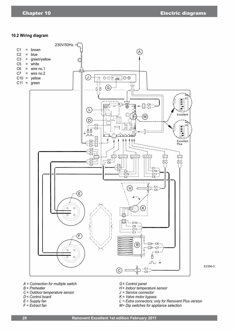
10.2 Wiring diagram
Chapter 10 Electric diagrams
E2356-C
C1 = brownC2 = blueC3 = green/yellowC5 = whiteC6 = wire no.1C7 = wire no.2C10 = yellowC11 = green
A = Connection for multiple switchB = PreheaterC = Outdoor temperature sensorD = Control boardE = Supply fanF = Extract fan
G= Control panelH = Indoor temperature sensorJ = Service connectorK = Valve motor bypassL = Extra connectors; only for Renovent Plus version M= Dip switches for appliance selection

Renovent Excellent 1st edition February 2011 29
Electric connections accessories Chapter 11
eBus or. OpenTherm connector X1Two-pole screw connector.Set ex factory as eBus connector; after modifying parameter 6 in the Settings menu, also suitable as OpenTherm connector (see §11.3.2). Only suitable for low voltage Note: For the eBus Application, this connector is polarity-spe-
Modular connector X2 for rpm controlModular connector type RJ-12.Only suitable for low voltage
Two-pole screw connector (accessible after taking off display cover).Ex factory this connector is not activated; after changing para-meter 11 in the settings menu from “OFF” to “ON”, this connector can be used for connecting the postheater.Maximum rated power is 1000W.Note: The postheater temperature sensor must also be con-
nected to X15-7 and X15-8.
For the Plus version, use the additionally mounted pull relief in the display cover to feed the 230 V cable to the postheater.
1 2 3 4 5 6 7 8 9
Nine-pole screw connector
Connection Application
1 & 2 External switch contact; for activation put para-meter 16 to 1 (see §11.6) orfor conversion to 0-10 V input, put parameter 3to “ON” (see §11.7).(X15-1 = GND & X15-2 = 0-10V)
3 & 4 ; ex factory activated (X15-3 = GND & X15-4 = 0-10V)orfor conversion to external switch contact,put parameter 19 to “OFF” (see §11.7).
5 & 6 , 4.5 VA maximum(5 = ground , 6 = +)
7 & 8outdoor geo heat exchanger
9 ( 9 = + , 5 = ground)

30 Renovent Excellent 1st edition February 2011
Chapter 11 Electric connections accessories
Wire colours C1 - C6 may vary dependent on the type of modular cable used.
Note: For the modular cable use, the “tab” of both modular connectors must be mounted facing the mark on the modular cable.
A = Renovent ExcellentB = Receiver for wireless remote control C = Transmitter with 4 settings (e.g. kitchen)D = Transmitter with 2 settings (e.g. bathroom)E = Any additional 2- or 4-settings trans-
mitters (A maximum of 6 transmitters can be signed on to 1 receiver)
A = Renovent Excellent
C = Splitter
A = Renovent Excellent
C = Receiver for wireless remote controlD = Transmitter with 2 settingsE = Splitter
E2365-AE2365-A
A multiple switch can be connected to the modular connector X2 of the Renovent Excellent. This modular connector X2 is directly accessible at the rear of the display cover (see §11.1) without having to take it off.
230 V50 Hz
230 V50 Hz
230 V50 Hz 230 V
50 Hz
A = Renovent Excellent
11.2.4 Additional multiple switch with wireless remote control

Renovent Excellent 1st edition February 2011 31
A = Multiple switchB = Modular splitterC1 - Cx = Renovent Excellent; modular coupling of a maximum of 12 appliances is possible.
E2364-A
Electric connections accessories Chapter 11
A maximum of 12 appliances
A = Multiple switchB = 2-pole connectorM = Renovent Excellent (Master)C1 - C* = Renovent Excellent (Slave); couple not more than 10 appliances through Ebus
Renovent set as “Master”.
E2364-A
A maximum of 10 appliances(1 Master + 9 Slave max.)
For M (Master):set parameter 7 to 0 (= factory setting).Display shows ventilation mode 1, 2 or 3.
For C1 (Slave1):set parameter 7 to 1 (= Slave 1).
Important:Because of polarity sensitivity, always connect contacts X1-1 to X1-1 and contacts X1-2 to X1-2. Never connect X1-1 and X1-2.
230 V50 Hz
230 V50 Hz
230 V50 Hz
230 V50 Hz
230 V50 Hz
230 V50 Hz
For C2 (Slave2):Set parameter 7 to 2 (= Slave 2).
Parameter Description Factorysetting Range
6 Communicationtype eBus 0T ( = Opentherm)
eBus
7 eBus address 0 0 = master1 - 9 = 9 slave 1 - 9

32 Renovent Excellent 1st edition February 2011
Chapter 11 Electric connections accessories
C1 = brownC2 = blueC3 = green/yellowC4 = blackC5 = white
A = Renovent Excellent PlusB = Plus version control boardC = Heating coil ( 1000W max.)D = Temperature sensorE = Maximum safety with manual resetF = LED maximum safety; lights up when activatedG = Cables to be connected by installerH = Flow direction through postheater
E2362-B
Parameter Description Factorysetting Range
11 Postheater OFF ON = Switched onOFF = Switched off
12 Temperaturepostheater 21°C 15°C - 30°C

Renovent Excellent 1st edition February 2011 33
Electric connections accessories Chapter 11
A = Renovent Excellent PlusB = Plus version control board mounted C = Three-way valve 24 volt; control 0-10 V.D = Geo heat exchangerE = Heat exchanger in Renovent Excellent Plus
OPERATING PRINCIPLE GEO HEAT EXCHANGER
A geo heat exchanger can be connected to the Renovent Excellent Plus.A geo heat exchanger can be connected to connection no. 5 (GND) and no. 9 (+) of 9-pole connector X15; this 9-pole connector is directly accessible at the rear of the top without having to dismount the display cover.When the geo heat exchanger is connected, it is not possible any more to connect a postheater to the Renovent!
E2366-B
WIRING DIAGRAM GEO HEAT EXCHANGER
E2366-B
When using a geo heat exchanger, parameter 25 must be changed from “OFF” to “ON”. When the air is routed through the geo heat exchanger, the Renovent Excellent Plus display shows the text “EWT”.
Parameter no. Description Factory setting Range
25 Switching on geo heat exchanger OFF ON = Switched onOFF = Switched off
26 Minimum temperature geo heat exchanger 5°C 0 - 10°C
27 Maximum temperature geo heat exchanger 25°C 15 - 40°C
A = Renovent Excellent PlusB = Plus version control boardC = Three-way valve 24 volt; (max. E
4.5 VA); control 0-10 V.D = Air from geo heat exchangerE = Outdoor air
G = Air to Renovent Excellent Plus
230 V50 Hz
9-pole connector X15
I = To dwelling
II = To atmosphere
III = From dwelling
IV = From atmosphere
34 Renovent Excellent 1st edition February 2011
Chapter 11 Electric connections accessories
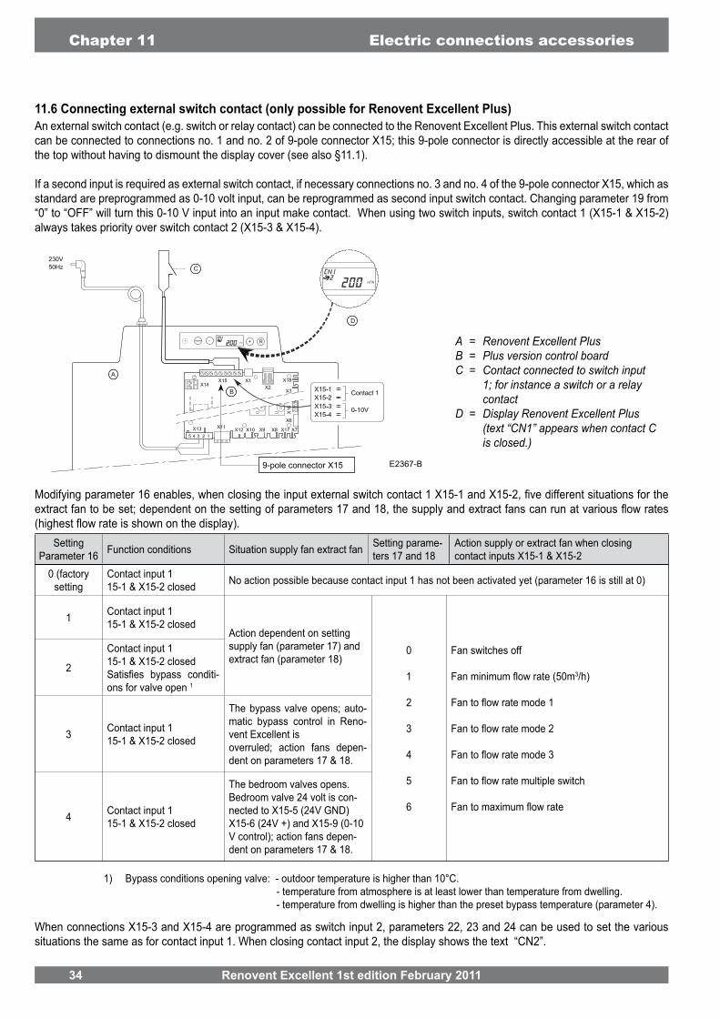
An external switch contact (e.g. switch or relay contact) can be connected to the Renovent Excellent Plus. This external switch contact can be connected to connections no. 1 and no. 2 of 9-pole connector X15; this 9-pole connector is directly accessible at the rear of the top without having to dismount the display cover (see also §11.1).
If a second input is required as external switch contact, if necessary connections no. 3 and no. 4 of the 9-pole connector X15, which as standard are preprogrammed as 0-10 volt input, can be reprogrammed as second input switch contact. Changing parameter 19 from “0” to “OFF” will turn this 0-10 V input into an input make contact. When using two switch inputs, switch contact 1 (X15-1 & X15-2) always takes priority over switch contact 2 (X15-3 & X15-4).
E2367-B
When connections X15-3 and X15-4 are programmed as switch input 2, parameters 22, 23 and 24 can be used to set the various situations the same as for contact input 1. When closing contact input 2, the display shows the text “CN2”.
1) Bypass conditions opening valve: - outdoor temperature is higher than 10°C. - temperature from atmosphere is at least lower than temperature from dwelling. - temperature from dwelling is higher than the preset bypass temperature (parameter 4).
A = Renovent Excellent PlusB = Plus version control board C = Contact connected to switch input
1; for instance a switch or a relay contact
D = Display Renovent Excellent Plus (text “CN1” appears when contact C is closed.)
SettingParameter 16 Function conditions Situation supply fan extract fan Setting parame-
ters 17 and 18Action supply or extract fan when closing contact inputs X15-1 & X15-2
0 (factorysetting
Contact input 115-1 & X15-2 closed No action possible because contact input 1 has not been activated yet (parameter 16 is still at 0)
1 Contact input 1 15-1 & X15-2 closed
Action dependent on setting supply fan (parameter 17) and extract fan (parameter 18)
0
1
2
3
4
5
6
Fan switches off
3/h)2
Contact input 115-1 & X15-2 closed
-ons for valve open 1
3 Contact input 115-1 & X15-2 closed
The bypass valve opens; auto-matic bypass control in Reno-vent Excellent isoverruled; action fans depen-dent on parameters 17 & 18.
4 Contact input 115-1 & X15-2 closed
The bedroom valves opens.Bedroom valve 24 volt is con-nected to X15-5 (24V GND)X15-6 (24V +) and X15-9 (0-10 V control); action fans depen-dent on parameters 17 & 18.
9-pole connector X15
Renovent Excellent 1st edition February 2011 35
Electric connections accessories Chapter 11
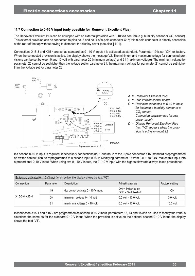
The Renovent Excellent Plus can be equipped with an external provision with 0-10 volt control) (e.g. humidity sensor or CO2 sensor). This external provision can be connected to pins no. 3 and no. 4 of 9-pole connector X15; this 9-pole connector is directly accessible at the rear of the top without having to dismount the display cover (see also §11.1).
Connections X15-3 and X15-4 are set as standard as 0 - 10 V input; it is activated as standard. Parameter 19 is set “ON” ex factory. When the connected provision is active, the display shows the message V2. The minimum and maximum voltage for connected pro-visions can be set between 0 and 10 volt with parameter 20 (minimum voltage) and 21 (maximum voltage). The minimum voltage for parameter 20 cannot be set higher than the voltage set for parameter 21; the maximum voltage for parameter 21 cannot be set higher than the voltage set for parameter 20.
E2368-B
A = Renovent Excellent PlusB = Plus version control boardC = Provision connected to 0-10 V input;
for instance a humidity sensor or a CO2 sensor.
Connected provision has its own power supply.
D = Display Renovent Excellent Plus (text “V2” appears when the provi-sion is active on input 2.)
If connection X15-1 and X15-2 are programmed as second 0-10 V input, parameters 13, 14 and 15 can be used to modify the various situations the same as for the standard 0-10 V input. When the provision is active on the optional second 0-10 V input, the display shows the text “V1”.
If a second 0-10 V input is required, if necessary connections no. 1 and no. 2 of the 9-pole connector X15, standard preprogrammed as switch contact, can be reprogrammed to a second input 0-10 V. Modifying parameter 13 from “OFF” to “ON” makes this input into
Ex factory activated 0 - 10 V input (when active, the display shows the text “V2”)
Connection Parameter Description Adjusting range Factory setting
X15-3 & X15-4
19 do/ do not activate 0 - 10 V input ON = Switched onOFF = Switched off ON
20 minimum voltage 0 - 10 volt 0.0 volt - 10.0 volt 0.0 volt
21 maximum voltage 0 - 10 volt 0.0 volt - 10.0 volt 10.0 volt
9-pole connector X15
X15-1 GNDX15-2 0-10VX15-3 GNDX15-4 0-10V

36 Renovent Excellent 1st edition February 2011
Chapter 12 Service
12.1 Exploded viewWhen ordering parts, in addition to the article code number (see exploded view), please state the type of the heat recovery appliance, the serial number, the year of production and the name of the part:
N. B.:Appliance type, serial number and year of production are
-ce.
12.2 Service parts
ExampleAppliance type : Renovent Excellent 4/0 R
Serial number : 420020111201
Year of production : 2011
Part : Fan
Article code : 531774
Qty : 1
12
EX105571-B

Renovent Excellent 1st edition February 2011 37
No. Article description Article code
1 531770
531771
Filter kit 1x G3 & 1x F7* 531773
2 Fan (1 pcs) 531774
3 Temperature sensor 531775
4 Control panel 531776
5 Heat exchanger 531777
6 Motor bypass valve 531778
7 Bypass valve 531779
8 Control board (Plus version) When replacing, note the correct dip switch settings; see §8.1 531780
9 Heating coil 1000 W preheater 531781
10 Cable with power plug 230 volt with display cover* 531782
11 Filter door right 531790
Filter door left 531792
12 Front cover right 242692
Front cover left 242738
* The mains cable has a print connector.When replacing it, always order a replacement mains cable Brink
Service Chapter 12

38 Renovent Excellent 1st edition February 2011
STEPNO. ADJUSTING RANGE STAP Display TEXT +
01 100 m3/h 50 m3/h - 400 m3/h 5 m3/h
02 200 m3/h 50 m3/h - 400 m3/h 5 m3/h
03 300 m3/h 50 m3/h - 400 m3/h 5 m3/h
04 Bypass temperature 22.0 °C 15.0°C - 35.0°C 0.5 °C BYPASS
05 Operation bypass valve 00 (= Automatic)1 (= Bypass valve closed)2 (= Bypass valve open)
BYPASS
06 Communication eBus Ot ( = Opentherm)eBus OT/BUS
07 Bus address 0 0 - 9 (0 = Master) BUSADR
08 Central heating + heat recovery OFF OFF (=Central heating+heat recovery off)
ON (= Central heating+heat recovery on)Central heating + heat recovery
09 Imbalance permissible ON ON (= imbalance permissible)
10 Fixed imbalance 0 m3/h -100 m3/h - 100 m3/h 1 m3/h
STEPNO. ADJUSTING RANGE STEP
11 Postheater OFF OFF (= Switched off)ON (= Switched on) HEATER
12 Temperature postheater 21.0 °C 15.0°C to 30.0°C 0.5 °C HEATER
13 Selection input 1 OFF OFF ( = switching input 1 active)ON (= 0 - 10 volt input 1 active) V1
14 Minimum voltage input 1 0.0 V 0 volt - 10 volt 0.5 V V1 MIN
15 Maximum voltage input 1 10.0 V 0 volt - 10 volt 0.5 V V1 MAX
16 Conditionsswitching input 1 0
0 (off)1 (on)2 (= On if conditions bypass
3 (= Bypass control)4 (= Bedroom valve)
CN1
17 Supply fan mode switching input 1 5
0 (= Input fan off)3/h)
2 (= Flow rate mode 1)3 (= Flow rate mode 2)4 (= Flow rate mode 3)5 (= Multiple switch 6 (= Maximum
CN1
18 Extract fan mode switching input 1 5
0 (= Extract fan off)3/h)
2 (= Flow rate mode 1)3 (= Flow rate mode 2)4 (= Flow rate mode 3)5 (= Multiple switch)
CN1
Chapter 13 Setting values

Renovent Excellent 1st edition February 2011 39
STEPNO. ADJUSTING RANGE STEP
19 Selection input 2 ON OFF ( = Switching input 2 active)ON (= 0 - 10 volt input 2 active) V2
20 Minimum voltage input 2 0.0 V 0.0 volt - 10.0 volt 0.5 V V2 MIN
21 Maximum voltage input 2 10.0 V 0.0 volt - 10.0 volt 0.5 V V2 MAX
22 Conditionsswitching input 2 0
0 (off)1 (on)2 (= On if conditions
3 (= Bypass control)4 (= Bedroom valve)
CN2
23 Supply fan mode switching input 2 5
0 (= Input fan off)3/h)
2 (= Flow rate mode 1)3 (= Flow rate mode 2)4 (= Flow rate mode 3)5 (= Multiple switch)
CN2
24 Extract fan mode switching input 2 5
0 (= Extract fan off)3/h)
2 (= Flow rate mode 1)3 (= Flow rate mode 2)4 (= Flow rate mode 3)5 (= Multiple switch)
CN2
25 Geo heat exchanger OFF
OFF (= Valve control geo heatexchanger off)
ON (= Valve control geo heatexchanger on)
EWT
26
Minimum temperature geo heat exchanger(Below this temperature the valve opens.)
5.0 °C 0.0°C - 10.0°C 0.5 °C EWT T-
27
Maximum temperature geo heat exchanger(Above this temperature the valve opens.)
25.0 °C 15.0 °C- 40.0 °C 0.5 °C EWT T+
Setting values Chapter 13
without prior notice.
40 Renovent Excellent 1st edition February 2011
DECLARATION OF CONFORMITY
Manufacturers : Brink Climate Systems B.V.
Address: R.D. Bügelstraat 3 7954 DA Staphorst, The Netherlands
Product: Heat recovery unit type: Renovent Excellent 400 Renovent Excellent 400 Plus
The product described above complies with the following directives:
2006/42/EC (machine directive) 2006/95/EC (low voltage directive) 2004/108/EC (EMC directive) RoHS 2002/95/EC (substances directive)
The product bears the CE label:
Staphorst, 24-02-11
W. Hijmissen,managing director


Brink Climate Systems B.V. R.D. Bügelstraat 3 7951 DA Staphorst Mailbox 11 7950 AA Staphorst The NetherlandsTelephone +31 522 46 99 44 Fax +31 0522 46 94 00 [email protected] www.brinkclimatesystems.nl
6120
54 1
e ed
ition
Febr
uari
201
1


![Versioni Dati tecnici - VMC Brescia€¦ · Versioni Dati tecnici Renovent Excellent 300 Tensione di alimentazione [V/Hz] 230/50 Grado di protezione IP30 Dimensioni (larghezza x altezza](https://img.pdfslide.net/doc/110x75/5eabfa74ce60b815ea3c6c7c/versioni-dati-tecnici-vmc-versioni-dati-tecnici-renovent-excellent-300-tensione.jpg)


![[XLS]obcindia.co.inobcindia.co.in/obcnew/upload/obc/Unpaid Dividend 2013-14... · Web view400 400 400 400 400 400 400 400 400 400 400 400 400 400 400 400 400 400 400 400 400 400 400](https://img.pdfslide.net/doc/110x75/5aa6f94e7f8b9a54748b6a16/xls-dividend-2013-14web-view400-400-400-400-400-400-400-400-400-400-400-400.jpg)