Embed Size (px)
Citation preview

To ensure that the system is installed properly, provide your electrician with these
instructions.
INSTALLATION INSTRUCTIONS
Solid-State Series
!! NOTE !!
Covers the following models:
" CS6100 - CS7100 " CS6200 - CS9200" CS6220 - CS9220" CS6230 - CS9230" CS6500 - CS7500" CS6330 - CS9300" CS9400 - CS9700
Refer to INSERT for additional information

A qualified and licensed electrician in accordance with the National Electric Code (NEC) Article 680, Canadian Electric Code, and with any local codes must accomplish the electrical installation.
All connections must be made according to the electrical installation label on the outside of the control box (see page 12). Follow the instructions from the label if they are different than the instructions in this manual. If your electrician is not absolutely sure how to connect your system correctly, call your local dealer. Any mistake may be costly and void your equipment warranty.
The GFCI (Ground Fault Circuit Interrupter) is a mandatory electrical safety device required for all portable spas and hot tubs as specified in the National Electrical Code Article 680-42. The GFCI in your particular installation may be installed at the electrical service panel, a separate sub-panel or built into your Hydro-Quip System.
Your spa equipment requires a DEDICATED CIRCUIT. No other appliances or lights can be on this circuit. Refer to equipment data label for power supply requirements of your spa equipment.
Use copper conductors ONLY. The ground must be sized following the National Electric Code, Table 250-95.
For Power conductor size, refer to the National Electric Code Table 310-16.
NOTE: Due to the electrical requirements of some models, it may be required to SPLIT the incoming electrical service to accommodate the GFCI Circuit Breaker limits. Contact your electrician if you need additional information on this topic.
15A 20A 30A 40A 50A 60A 70A 80A
12A 16A 24A 32A 40A 48A 56A 64A
14 12 10 8 6 4 4 4
Circuit & BreakerRating
Maximum Amps
Minimum WireSize
Universal Systems require a Neutral wire therefore the service required is as follows: 120-volt systems require a three-wire electrical service including ground, consisting of Line 1 (Black), Neutral (White) and Ground (Green). 240-volt systems require a four wire electrical service including ground, consisting of Line 1 (Black), Line 2 (Red), Neutral (White) and Ground (Green).
1
ELECTRICAL INSTALLATION

2
If your system was configured to include a 120VAC power cord, ensure that the proper receptacle has been installed (a dedicated circuit is required). DO NOT under any circumstances modify a 20 Amp plug to fit into a 15 Amp receptacle or use an extension cord. Doing so will create hazardous conditions and/or void the warranty.
OPTION 1
20AMP CORDEND GFCI
PORTABLE SPA
DEDICATED15A/120V OUTLET
This illustration depicts a typical 20 AMP, cord-end GFCI installation. (The spa must be installed on a dedicated circuit.)
DO NOTUSE AN
EXTENSIONCORD15 AMP
RECEPTACLE20 AMP
RECEPTACLE
Units with 15A GFCI Plug Connection
MAIN BREAKER PANEL
ELECTRICAL CONNECTION

3
PORTABLE SPA
INLINE SPA DISCONNECT
GFCI DISCONNECT
LIN
E 1
N
LIN
E 2
INLINE SPA DISCONNECT
20-60AMP HARDWIRED
Power from GFCI breaker installed into main service panel to a service disconnect within line-of-site of the spa.
Power from main service panel to a GFCI subpanel within line-of-site of the spa. (Note: Most local codes will allow a GFCI subpanel to be a disconnect. If this is not the case in your installation, a disconnect must be provided.)
TO PORTABLE SPA
REFER TO GFCI WIRING DETAIL
REFER TO GFCI WIRING DETAIL
MAIN BREAKER PANEL
LINE 1
N
LINE 2
20-60AMPHARDWIRED
If the manufacturer of your homes main breaker panel makes a GFCI breaker, you may be able to add it to an open slot in the panel.
GFCI Installed in Main Service Panel
Subpanel GFCI Installed
MAIN BREAKER PANEL
ELECTRICAL CONNECTIONS
OPTION 2
OPTION 2a

4
HEATER
ON
POWERCONTROLSWITCHRefer to OperationManual for testingand operationalprocedures
Pump 1
*Pump 2
Air
*Pump 3
*Aux.
Light
Ozone
*Circ.
*Aux.
SOLID-STATECONTROL SYSTEM
*Optional
MAIN BREAKER PANEL
PORTABLE SPA CONTROL w/BUILT-IN GFCI
INLINE SPA DISCONNECT
BUILT-IN SYSTEM GFCI
Power from main breaker panel to service disconnect within line-of-site of the spa to portable spa control equipped with buit-in GFCI.
Refer to the System Data Label for equipment voltage and maximum amperage draws.
Install proper size Ground Fault Circuit Interrupter (GFCI) or circuit breaker, then proper sized wiring and bonding wire. For Power conductor size, refer to the National Electric Code Table 310-16. For Ground conductor size, refer to the National Electric Code Table 250-122.
A bonding lug has been provided on the control box to allow connection to local ground points. To reduce the risk of electrical shock, a solid copper bonding wire should be connected from this lug to any metal ladders, water pipes or other metal object within 5 feet of the spa.
WARNING - BE SURE THAT YOUR POWER SUPPLY CIRCUIT CAN ADEQUATELY HANDLE THE AMPERAGE YOU SELECT.
The control input power wiring may have been provided. Following NEC and local codes in effect at the time of installation, connect (refer to wiring diagram located on the inside of control hinged cover) the Black wire to input Line 1, Blue wire to input Line 2 (if applicable), White wire to Neutral and the Green wire to ground.
ELECTRICAL INSTALLATION DETAILS
!
IMPORTANT - The NEC and most local codes require that a “disconnect” be installed within “line-of-site” of the spa.
ON
OFF
RESET
TESTLocated on left side of control box.
N
Systems with GFCI IncludedYour system may have an integrated GFCI located on the left side of the control box as shown below. If a GFCI is present there is NO need for additional GFCI protection illustrated in options 2 & 2a.
ELECTRICAL CONNECTION
OPTION 3

5
When a GFCI circuit breaker is used in the installation of your spa, it is important that it has been properly installed. Often this component has been improperly installed causing the breaker to trip the instant the system is turned on. Below is an illustration of a typical GFCI breaker installation.
WARNING: Refer to Circuit Breaker Manufacturers installation instructions. This illustration is meant to be a guide for Field Technicians and is not intended to override or substitute the instructions supplied with the circuit breaker.
GFCI
TEST
(Ground Fault Circuit Interrupter)
CIRCUIT BREAKER
NEU
TR
AL P
IGTAIL
NEU
TR
AL B
US B
AR
LINE 1
NEUTRAL
LINE 2
GROUND
GROUND BUS BAR
LINE LUG #1 LINE LUG #2
LINE 1LINE 2
INCOMINGSERVICE
CONDUCTORSFROMMAINPANEL
NEUTRAL
GROUND
TO SPA CONTROL SYSTEM
LOAD
LOAD NEUTRAL MUST BE CONNECTEDDIRECTLY TO GFCI AS SHOWN
GFCI WIRING DETAIL

6
The control circuits have been configured for 120V components at the factory. This is to prevent accidental damage to equipment. A 240V component connected momentarily to a 120V power supply will not be damaged. A 120V component connected to a 240V power supply can be damaged immediately. For this reason Hydro-Quip cannot be held responsible for damage caused due to mis-wire.
Below are illustrations and instructions for converting the universal circuits of your control. Colored connectors are utilized to help identify each circuit. Simply locate the colored connector on the Neutral (white) wire from each components receptacle. Using the wiring diagram provided with each control (located inside the hinged cover), remove the Neutral connector from its 120V / Neutral position and reconnect to the 240V / Line 2 connection (shown in parenthesis on the wiring diagram). Once accomplished the conversion is complete. Repeat these steps as required for each 240V component.
PUMP 1
PUMP 2
RED
VIOLET
BLOWER BLUE
OZONE
CIRC. PUMP
YELLOW
BROWN
CIRCUIT COLOR CIRCUIT COLOR
(2) Reinstall connector onto 240V connection
(1) Remove connector from 120V connection
!! IMPORTANT !! All Systems are Universal
SYSTEM CONFIGURATION

RED:Pump 1 / 2-Speed
BROWN:Pump 2 / 2-Speed
PINK:Pump 1 or 2 / 1-Speed
PURPLE:Air Blower / 1-Speed
YELLOW:Ozone
BLUE:Circ. Pump
WHITE:12V Light or Fireman's Switch
LIGHT PURPLE:Switched Accessory
ORANGE:Fiber Optic
GREEN:Hot Auxiliary Circuit
RECEPTACLE GUIDE
To make things easy, we have developed our own unique set of color-coded cords & receptacles. Use the chart below when connecting components.
7
8
If your system includes a Versi-Heat remote heater, see illustration below to see which layout best fits your particular installation.
The heater can be installed vertical, horizontal or at an angle in the pumps discharge plumbing (providing position DOES NOT allow air pockets to form inside the housing). The heater can be installed up to 5-feet from the control system, which is connected via a black 3-conductor and black 6-conductor cord to the black receptacles provided at the control box..
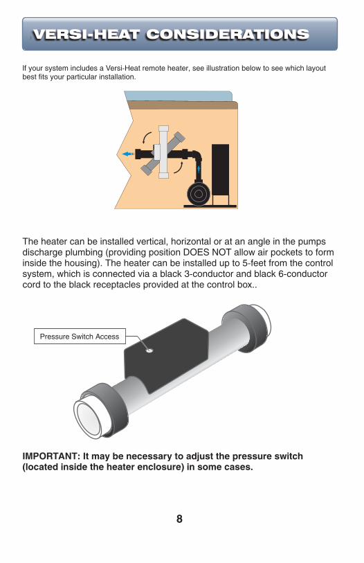
IMPORTANT: It may be necessary to adjust the pressure switch (located inside the heater enclosure) in some cases.
VERSI-HEAT CONSIDERATIONS
Pressure Switch Access
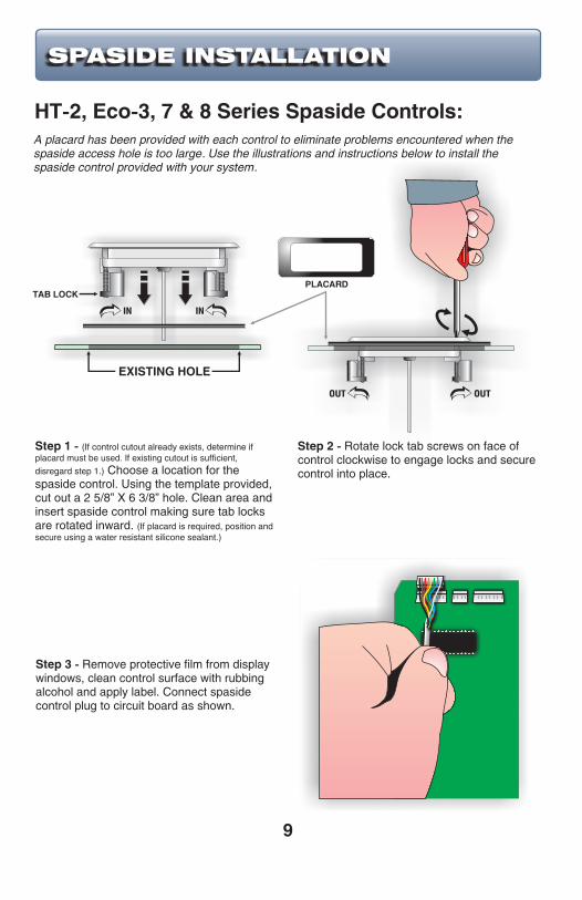
A placard has been provided with each control to eliminate problems encountered when the spaside access hole is too large. Use the illustrations and instructions below to install the spaside control provided with your system.
Step 1 - (If control cutout already exists, determine if placard must be used. If existing cutout is sufficient,
disregard step 1.) Choose a location for the spaside control. Using the template provided, cut out a 2 5/8” X 6 3/8” hole. Clean area and insert spaside control making sure tab locks are rotated inward. (If placard is required, position and secure using a water resistant silicone sealant.)
Step 2 - Rotate lock tab screws on face of control clockwise to engage locks and secure control into place.
Step 3 - Remove protective film from display windows, clean control surface with rubbing alcohol and apply label. Connect spaside control plug to circuit board as shown.
9
HT-2, Eco-3, 7 & 8 Series Spaside Controls:
IN IN
EXISTING HOLE
PLACARD
OUT OUT
SPASIDE INSTALLATION
TAB LOCK

10
Step 1 - (If control cutout already exists, determine if placard must be used. If existing cutout is sufficient,
disregard step 1.) Choose a location for the spaside control. Using the template provided, d
lean area and insert spaside. (If placard is required, position and secure using a water resistant silicone sealant.)
rill two 1” diameter holes, 2 5/8” apart. Cut away the material between the two holes, c
Step 2 - Route cord through the hole, remove the double-sided adhesive tape on the back of the keypad. Now carefully adhere the keypad to the spa shell or placard making sure it is straight.
Step 3 - Remove protective film from display window, clean control surface with rubbing alcohol and apply label. Connect spaside control plug to circuit board as shown.
Eco-1, 2, 5 & 6 Series Spaside Controls:
PLACARD
SPASIDE INSTALLATION
EXISTING HOLE
DOUBLE-SIDED TAPE

11
Option #1 Preferred Method - DRYWELL: If the existing placement of your temperature sensor does not allow for an accurate temperature reading a drywell may have to be installed in the spa wall. Once a location has been chosen, cut a 1 1/8” hole (cut from inside the spa). Clean excess debris from around the hole. Use a water resistant silicone applied to the sealing surfaces and insert the drywell into the hole. Tighten the drywell nut ( DO NOT over tighten). Insert temperature sensor into drywell and insert grommet as shown below. Allow silicone to cure for 24-hours.
SEALING SURFACE
SEALING SURFACE
GROMMET
TEMPERATURESENSOR
Using a suitable 2“ diameter hole-saw, cut a hole in the spa wall. Cut from inside the spa wall toward the outside to prevent splintering the inner surface. Remove any insulation material from around the hole (at least 2“) at the outside spa wall. Install the gasket onto the light body and install the light into the hole. Take care not to over tighten the nut securing the light body. (Silicone sealant may be used in place of the gasket. Allow adequate time for sealant to cure before filling the spa.)
Gasket
Light Body
Spa Wall
Light Bulb
TEMP. SENSOR INSTALLATION
SPA LIGHT INSTALLATION
Option #2 Alternate Method - HEATER HOUSING: If it is not possible or desired to drill a hole into the spa shell the temperature sensor may be installed with the High-Limit sensor directly on to the heater housing under the sensor shield/cover. Simply loosen, insert probe as shown and re-tighten.
12
Using the “System Operation Manual” provided with the unit, complete the following procedures:
1) Read and familiarize yourself with the system Operation manual.
2) Unplug the power cord (120-volt system only) or turn the electrical power “OFF” at the service or breaker panel (120 or 240 volt permanently connected units.)
3) Open all WATER shut-off valves.
4) For spas equipped with a hose bib or drain valve, make sure that it has been closed.
5) For spas equipped with in-line or pressure water filters, make sure that the filter nut, housing drain plug, and air relief valve are closed and tight.
6) Using a standard water hose, fill the spa with fresh tap water to the level recommended by the spa manufacturer.
7) Inspect all plumbing connections and lines for any sign of water leaks.
8) Close all AIR control valves. WARNING: Do not confuse with WATER shut-off valves.
9) Plug the unit into the proper outlet (120-volt system) or turn on the breaker at the electrical service panel (240-volt system).
10) Adjust temperature to the lowest setting.
11) On units with a Ground Fault Circuit Interrupter (GFCI), check the GFCI by pressing the “Test” button on the face of the device. The “Reset” button should pop out. The equipment should not operate.
12) Activate the equipment by pressing the “Reset” button on the GFCI. (If the jet pump(s) or blower is operating, switch them off).
13) Press the “JET PUMP” switch to run on high speed. Allow to run until you achieve a strong, steady water flow (free of air bubbles).
14) On systems with a pressure filter, bleed off the trapped air by opening the Air-Relief valve. You will notice a steady flow of water when the air has been bled completely.
15) Switch the “JET PUMP” off.
16) If equipped, switch the “AIR BLOWER” on to verify that it is working, then switch it off.
17) If equipped, switch the “LIGHT” on to verify that it is working, then switch it off.
18) If equipped, switch the “AUXILIARY PUMP” on to verify that it is working, allow to run until all air is evacuated from the plumbing system, then switch it off.
19) Adjust temperature to the desired set point for comfortable use of the spa. The pump low speed and heater will activate until the set point has been reached.
It is now time to turn over operation of the spa to the homeowner. See next section for basic troubleshooting tips.
System Startup Procedures:
SYSTEM STARTUP

13
The following describes situations and possible solutions to common problems may encounter as a spa owner. Note: your system may not include all components listed.
Main Breaker is OFF - Set to On.Sub-Panel Breaker Off - Set to On.System GFCI Off - Set to On.Power switch in Off position - Set to On.Components not plugged in - Plug in components.
Air Lock in Plumbing System - “Bleed” the system.Restricted Flow - Insure that the water shut-off valves are open and that suction
fittings are not blocked by debris.Low Water Level - Increase water level to recommended level.
Pump 1 Not Plugged-In - Plug in Pump 1.Pump 1 Fuse Blown - Contact your local dealer.Pump 2 Not Plugged-In - Plug in Pump 2.Pump 2 Fuse Blown - Contact your local dealer.
Blower or Pump Not Plugged-In - Plug in the Blower or Pump.Pump or Blower Fuse Blown - Contact you local dealer.
TROUBLESHOOTING
NOTHING OPERATES
NO, LOW or SURGING WATER FLOW
NO LOW SPEED OPERATION
NO JETS or BLOWER OPERATION

14
NO THERAPY JET OPERATION
Water Shut-Off Valves are Closed - Open Shut-Off valves.Jets Not Properly Adjusted - Adjust Jets properly.Diverter Valve Not Properly Adjusted - Adjust diverter valve properly.Thermal Overload Tripping - Check for restricted flow of water.
Temperature Not Set Correctly - Adjust “Set Point” Temperature. System Power Restriction - Depending on available power, the spa may have interlocks in place to shut off the heater when the pumps are switched to high speed.No Power - Reset breaker at service panel.Low Water Flow - Clean or Replace filter.Pressure Switch Not Adjusted Properly - Refer to “Pressure Switch Adjustment”.
Temperature Sensor Not in Dry-Well - Place sensor in dry-well.Temperature Set Too High - Adjust “Set Point” Temperature.High Ambient Temperature - Remove spa cover.
Light Bulb Defective - Replace bulb or contact your local dealer.Reflector has Fallen Off - Replace deflector or contact your local dealer.Light Not Plugged-In - Plug in the Light.
Spa Overfilled - Adjust water level.Drain-Valve Left Open - Close drain valve.Couplings or Unions Loose - Tighten or contact your local dealer.Pump Seal Leaking - Contact your local dealer.Plumbing / Connections Leaking - Contact your local dealer.Water Leaking from Spaside Control - Contact your local dealer.Water in Air Blower Plumbing - Contact your local dealer.
For correct GFCI breaker wiring, refer to page 5 for details.
NO LIGHT OPERATION
WATER LEAKS
NO HEAT
HIGH HEAT
GFCI TRIPS IMMEDIATELY

15
If your system is equipped with a pressure switch, the function of the pressure switch is to turn the heater off if the pump stops operating or if there is a restricted water flow (dirty filter, obstruction in the spa plumbing etc.).
The pressure switch has been preset at the factory to operate properly with your spas specific plumbing. Adjustment or other service may be required if you observe a flow related problem (3 flashing dots on spaside display). If adjustment is required, follow the next steps carefully.
IMPORTANT: After any pressure switch adjustment, it is important to test the control by turning on the pump low speed and heater. While operating, unplug the pump, the heater must turn off. If the heater stays on, plug the pump back in and readjust the pressure switch to achieve proper operation.
1) With power to system turned OFF, remove the wires from the pressure switch terminals (secure wires safely to prevent any chance of electrical shock).
2) Use temperature adjustment key to move “set point” temperature to its lowest setting.
3) Turn power to the system ON and activate the low-speed pump.
4) Place an Ohmmeter across the pressure switch terminals to verify an OPEN circuit.
5) Rotate the pressure switch adjustment screw counter-clockwise until the Ohmmeter indicates a CLOSED circuit.
6) Turn pump OFF and verify that the pressure switch circuit is once again OPEN.
7) Turn power to the system OFF and reconnect pressure switch wires. Reapply power to the system and operate the spa or hot tub as normal.
Adjustment
SPECIAL CONSIDERATIONS
Hydro-Quip 1A Pressure Switch
HQ PT# 34-0178
Adjustment Screw - Slotted
Hydro-Quip 1A Pressure Switch
HQ PT# 34-0178A
Adjustment Screw
T25 Torx, 5/32 Allen Wrench or
small slotted screw driver with a
5/32 tip.

The system data label is located on the control box. This label is very important and contains information you will need to establish your electrical service. The voltage and amperage ratings are shown on the bottom of the label. Product, Model, Serial and Code numbers are also shown on the label.
Note: This information will be necessary if you should ever have to request warranty or any other type of service.
REFER TO NEC FORBREAKER SIZING
ORDER CODE: CSXXXX
MODEL: XXXXXXX-XXXXXXXCODE: XXXX-XXXX-XXX
VOLTS: 120 240AMPS: SEE RATINGS LABEL
PRODUCT: HQXXXX
SYSTEM DATA INFORMATION
16
Corona, CA 92880 | www.hydroquip.com


18
Dealer:
Contact:
Address:
City:
Phone:
State: Zip:
Date of Install:
Notes:
Use this section to jot down any information you may need at a later date.
NOTES

85-0135A Rev. 6 02/11