Embed Size (px)
Citation preview
INSTALLATION INSTRUCTIONSFRONT DISC BRAKE CONVERSION KITS
SUM-BK1500, SUM-BK1500-DS, SUM-BK1501, SUM-BK1501-DS,
1964 - 72 A-BODY1967 - 69 F-BODY1962 - 74 X-BODY
(NOTE: 62-64 X-BODY REQUIRES 5-LUG STEERING ARMS)
_____________________________________________________________________
Thank you for choosing SUMMIT RACING EQUIPMENT for your braking needs. Please takethe time to read and carefully follow these instructions to insure the ease of your installation as wellas the proper performance of the complete system.
If you believe anything to be missing or incorrect, please call our Customer ServiceDepartment at 330-630-0240.
To assure your installation will go safely and smoothly, have the following items on hand toassist you:
JACK & JACK STANDS WRENCH SETLUG WRENCH TUBE WRENCHESTORQUE WRENCH MALLETSOCKET SET WHEEL BEARING GREASEBRAKE CLEANER BRAKE FLUID
1Part # INST01
1) Raise the vehicle until the wheels and tires clear the floor; support front of vehicle on jack stands. Make sure parking brake is engaged. Remove front wheels and tire assemblies.
2) Remove spindle assembly:a) Remove tie rod ends from spindle after removing retaining hardware. We strongly
recommend the use of a splitter "picklefork" for this purpose!b) Remove both front shock absorbers.c) Compress both front coil springs with appropriate spring compressor and remove from
car. The use of a safety chain around the control arms is recommended to prevent sudden spring unloading during this operation.
d) Disconnect both upper and lower ball joints and remove spindle assemblies from car.Separate ball joints from spindle.Remove hub from spindle, save for re-installation.
e) Retain all original hardware for possible reuse.
3) Install new spindle assembly:a) Check ball joints prior to re-assembly and if any play is indicated, replace with new
parts.
SPINDLE BEARING SURFACES ARE PRECISION MACHINED, PROTECT MACHINED SURFACES AGAINST DAMAGE.
BEFORE REINSTALLING STEERING ARMS, DRILL OUT FACTORY 7/16" HOLES TO 1/2" HOLES TO ENABLE REATTACHMENT TO SPINDLE.
NOTE: WHEN INSTALLING KITS ON 1962-64 CHEVY II / NOVA, 1965-67 V8 (5 LUG) STEERING ARMS WILL BE REQUIRED.
b) Install new spindles and ball joints. Make sure that steering arms point toward rear of car. Torque lower ball joint to 65ft-lbs, upper ball joint to 50 ft-lbs.
c) Re-install coil springs in reverse manner of removal.d) Re-install shock absorbers. Install curved steering arms onto new spindles as in the
reverse manner of removal. Note bolts are not the same length, rear bolts are 1/2”longer.
e) Re-install tie-rod ends and castellated nuts, torque to 35 ft-lbs. install new cotter pins
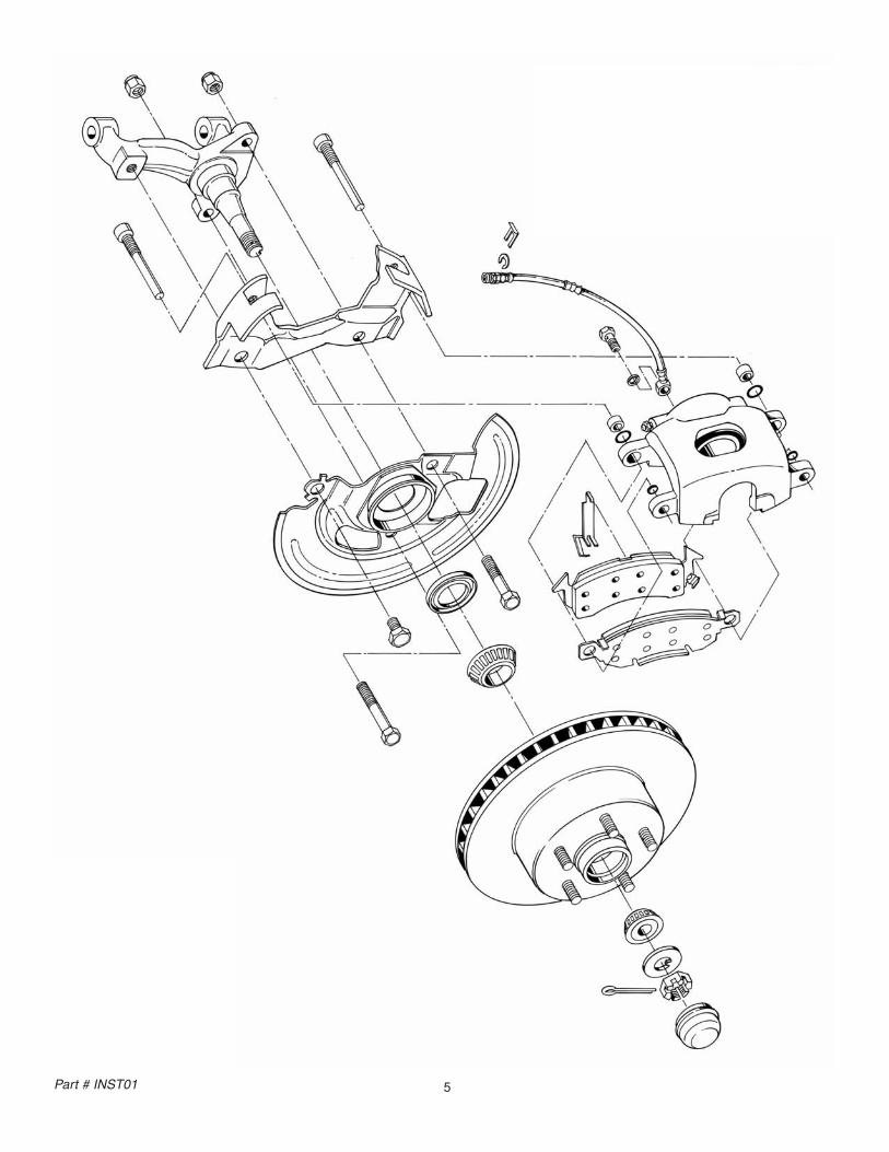
4) Install caliper mounting brackets and hardwarea) Place caliper mounting bracket over spindle with ears facing outward, 5/8"dia hole on
top.b) Place splash shield over bracket and secure both bracket and splash shield to spindle
with (1) 5/8"x 1" bolt and (2) 1/2"-20x2-1/2" bolts. Bend “tab-locks,” on splash shield against 1 bolt flat.
c) Install new wheel bearings, after packing with a good grade of wheel bearing grease.(Inner wheel bearings must first be installed in rotors and retained with provided grease seals). Use large socket or seal installer tool for correct seating of grease seal.
BE CAREFUL THAT ALL HYDRAULIC COMPONENTS ARE KEPT CLEAN AND FREE OF DEBRIS, INSIDE AND OUT. REMEMBER, DIRT IS THE ENEMY OF HYDRAULIC SYSTEMS. SUMMIT WILL NOT BE RESPONSIBLE FOR SYSTEM FAILURES DUE TO AN UNCLEAN INSTALLATION.
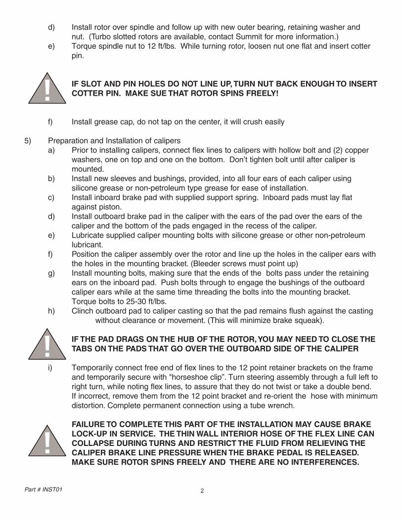
d) Install rotor over spindle and follow up with new outer bearing, retaining washer and nut. (Turbo slotted rotors are available, contact Summit for more information.)
e) Torque spindle nut to 12 ft/lbs. While turning rotor, loosen nut one flat and insert cotter pin.
IF SLOT AND PIN HOLES DO NOT LINE UP, TURN NUT BACK ENOUGH TO INSERTCOTTER PIN. MAKE SUE THAT ROTOR SPINS FREELY!
f) Install grease cap, do not tap on the center, it will crush easily
5) Preparation and Installation of calipers a) Prior to installing calipers, connect flex lines to calipers with hollow bolt and (2) copper
washers, one on top and one on the bottom. Don’t tighten bolt until after caliper is mounted.
b) Install new sleeves and bushings, provided, into all four ears of each caliper using silicone grease or non-petroleum type grease for ease of installation.
c) Install inboard brake pad with supplied support spring. Inboard pads must lay flat against piston.
d) Install outboard brake pad in the caliper with the ears of the pad over the ears of thecaliper and the bottom of the pads engaged in the recess of the caliper.
e) Lubricate supplied caliper mounting bolts with silicone grease or other non-petroleum lubricant.
f) Position the caliper assembly over the rotor and line up the holes in the caliper ears withthe holes in the mounting bracket. (Bleeder screws must point up)
g) Install mounting bolts, making sure that the ends of the bolts pass under the retaining ears on the inboard pad. Push bolts through to engage the bushings of the outboardcaliper ears while at the same time threading the bolts into the mounting bracket.Torque bolts to 25-30 ft/lbs.
h) Clinch outboard pad to caliper casting so that the pad remains flush against the casting without clearance or movement. (This will minimize brake squeak).
IF THE PAD DRAGS ON THE HUB OF THE ROTOR,YOU MAY NEED TO CLOSE THE TABS ON THE PADS THAT GO OVER THE OUTBOARD SIDE OF THE CALIPER
i) Temporarily connect free end of flex lines to the 12 point retainer brackets on the frame and temporarily secure with "horseshoe clip”. Turn steering assembly through a full left toright turn, while noting flex lines, to assure that they do not twist or take a double bend.If incorrect, remove them from the 12 point bracket and re-orient the hose with minimum distortion. Complete permanent connection using a tube wrench.
FAILURE TO COMPLETE THIS PART OF THE INSTALLATION MAY CAUSE BRAKE LOCK-UP IN SERVICE. THE THIN WALL INTERIOR HOSE OF THE FLEX LINE CAN COLLAPSE DURING TURNS AND RESTRICT THE FLUID FROM RELIEVING THE CALIPER BRAKE LINE PRESSURE WHEN THE BRAKE PEDAL IS RELEASED.MAKE SURE ROTOR SPINS FREELY AND THERE ARE NO INTERFERENCES.
2Part # INST01
3Part # INST01
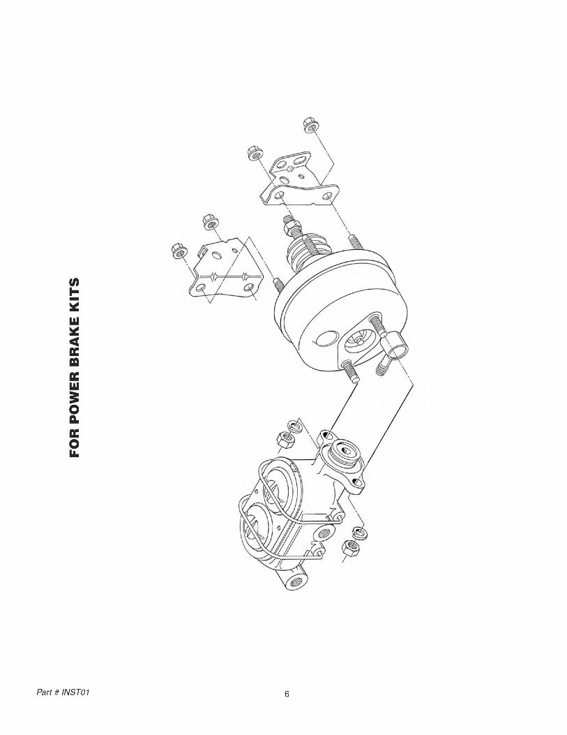
6) Power booster (For Power Disc Brake Kits)a) Remove original master cylinder and save clevis and associated hardware.b) If kit has been ordered with power brake option, line up booster to determine which bolts
require removal to allow attachment to fire wall. Remove four bolts and install booster (do not tighten fasteners at this time). Assemble jam nuts and clevis onto booster input shaft before final tightening.
c) Align holes of clevis with lower hole in brake pedal arm. Adjust clevis to allow 1/8" endplay and assure that stop light switch is still in adjustment.
d) The most convenient vacuum source for the booster is the engine intake manifold. Theminimum vacuum developed by the engine, at idle, should be no less than 18"hg. In addition, the rubber hose between the intake manifold and the booster must be rated for vacuum service and have an outside diameter of no less than 11/32”
e) An extension rod is supplied for those vehicles that need longer pushrods. (3/8-24 thread).
7) Master cylindera) Always bench bleed master cylinder before installing in car and refer to the separate
"Master Cylinder Installation Instructions."
8) Brake fluid and bleeding the systema) After completing all hydraulic connections, install new brake fluid (at master cylinder
reservoir). Remove the master cylinder and bench bleed the master cylinder. Pump brake pedal several times to initially fill the system and advance the caliper pistons to their working position.
WHEN BLEEDING THE SYSTEM, PUMP FLUID SLOWLY INTO THE NEW SYSTEM. IF FLUID “FOAMS”, IT WILL TAKE A LOT OF FLUID TO BLEED THE BRAKES. SOFT PEDAL IS A RESULT OF POOR BLEEDING. TAKE YOUR TIME!
8A) Bleeding the systema) When pressure bleeding is employed the correct pressure setting is 10-15 psi. (max.)
for the bleeder tank.b) If power brakes are fitted, the engine should not be running and the vacuum reserve
should be reduced to zero by pumping the brake pedal or pulling the booster vacuumhose.
c) Tapping the caliper with a rawhide mallet, before fluid is flowing, may assist in obtaining a better bleed job.
d) Brake bleeding can be simplified by assuring that there are no line restrictions, by using the gravity bleed approach as follows:1) Leave all bleeder screws open when installing calipers.2) Fill master cylinder reservoir, do not pressurize master cylinder or pump brake
pedal; instead observe bleeder ports until brake fluid flows out; then shut bleeder valves.
3) No further procedure is required if brake pedal is hard after shutting off all bleeder valves. Make sure that the master cylinder is "topped-off."
e) With bleeders closed and system bled, a hard pedal should be experienced so that at full application and with the engine running, the toe of your left foot can still be placedbetween the bottom of the pedal and the floor.1) In addition there should be brake pedal end-play of 3/4 to 1" inch (from full
release until initial braking action takes place).2) Power brake cars will experience a "drop-off" of the pedal when the engine is
started. This is a normal condition, and signifies that the booster is working correctly.
DO NOT DRIVE THE CAR UNTIL THE BRAKES STOP THE CAR SAFELY, INITIAL BRAKING TESTS SHOULD BE DONE IN A SAFE OPEN AREA! LOOK FOR LEAKS AND INTERFERENCES!
f) If brake pedal "end-play" is excessive, adjust push-rod between the brake pedal and booster (to lengthen) in 1/4 turn increments until 1" of "end-play" is achieved.
9) Final inspectiona) Reinstall wheel and tire assemblies.b) Recheck all mechanical and hydraulic connections, look for brake fluid leaks, recheck
brake pedal operation.c) Lower vehicle to ground and test braking system for proper operation in a safe area
before driving on public highways.
DO NOT DRIVE IN TRAFFIC UNTIL THE BRAKES SAFELY STOP THE CAR A SAFE DISTANCEWITHOUT A SPONGY PEDAL FEEL!
BRAKING TESTS SHOULD ALWAYS BE DONE IN A SAFE OPEN AREA!
TECH LINE -- If technical help is required, please call 330-630-0240.
NOW ENJOY TRUE PERFORMANCE BRAKING!!
4Part # INST01
5Part # INST01
6Part # INST01
FO
RP
OW
ER
BR
AK
EK
ITS
How do you bench bleed a MasterCylinder?
Secure one of the ears in a vise so that you can take alarge screwdriver and push the piston in. Fill thereservoir with clean fluid. Take a dummy line or our M/Cbleeding kit and hook it up to the two ports. Front line tofront and rear line to rear reservoirs. Slowly stroke themaster and let it return slowly. You should see many airbubbles in the fluid. Repeat this step until you do notsee any more air bubbles. Summit recommends ten(10) slow pumping strokes after you see no more airbubbles. This will insure a good hard pedal. (SeeSummit master cylinder bleeder kit instruction Sheet)
What is the best pad for my vehicle?
Your choice of pads should be determined by how andwhere you drive the vehicle. If you drive in heavy stopand go traffic you would need a different pad thansomeone who is road racing. Contact Summit for thecorrect application.
How often should brake fluid bechanged? (street application only,not racing)
When brake fluid turns brown, it is time to change thefluid. The brown color indicates that the fluid hasabsorbed water and dirt. D.O.T. #3 & #4 fluids absorbwater. Silicone brake fluid is not for track racing.
How can I tell which reservoir is thefront or rear of the Master Cylinder?
The front reservoir is usually larger than the rear. Insome cases, they are the same size. As a rule, for GMcars & trucks, the rear reservoir is for the rear brakes.On Ford cars & trucks, the front reservoir is for the rearbrakes. On front wheel drive vehicles, the brakes aresplit diagonally. Each bowl of the master cylinderservices one front wheel and one rear wheel. This willbe important if you are installing a distribution block,proportioning valve, or residual valve. Hint: The largerbowl will feed the disc brakes.
1
Why is my brake pedal soft?
1) In most cases, Air is trapped in the lines or calipers.Try re-bleeding the system. Do not force new fluid intonew brake lines. It may foam and be very difficult tobleed. Make sure that the bleeder screws on thecalipers are facing upward!
2) If all the air is out of the system, the pushrod fromthe booster may need adjustment, under the dash, tomake it longer. Do not extend it too long or it will notallow the fluid to return, causing brakes to drag. Yourpushrod may not be adjustable. If the pushrod can bemade longer, try ¼ turn adjustments at a time. Summitstocks adjustable pushrods for many vehicles. Inaddition, the pushrod between the Booster and theMaster Cylinder may need adjustment. Not all Boosterto Master pushrods are adjustable.
3) You may have a bad Master Cylinder. Before youdetermine this, you should make sure that all the air isout of the system. When installing a new MasterCylinder, always bench bleed first. If you did not, takeoff the Master Cylinder and bench bleed it. (See BenchBleeding Instructions below)
Why does the car pull to one side?
The side that the car is pulling to is the caliper that isworking. Re-bleed the opposite side and try carefullystopping again.
Why does it feel like there is noPower Assist?
The Booster may not be getting enough vacuum tooperate. On some high lift cams, the engine does notdevelop enough vacuum. The Booster needs at least16” of vacuum to operate correctly at idle. If you do nothave at least 16 inches of vacuum at idle, you may haveto add a vacuum pump to your system.Check for vacuum leaks. There may be leaks in theintake manifold or hoses that would cause low vacuum.The Booster may be bad. Do a vacuum test. If theBooster can retain a vacuum for three (3) minutes afterthe vehicle is shut off, it is not a bad Booster (refer tosteps 1 & 2). All Master Cylinders must be bench bledin a vise before being installed on the vehicle.
Solutions Guideto commonly asked questions.
2
Where is the best place to install aproportioning valve?
The best place to install a proportioning valve is afterthe distribution block. Do Not install it between theDistribution Bock and the Master Cylinder. You willnot be able to get a hard pedal. Anywhere after theDistribution Block and before the rear flex hose isacceptable for installation.
Why should the flex hoses bereplaced? They look O.K. from theoutside.
Flex hoses should be replaced every time the calipersare serviced. They flex up and down, just like a shockabsorber. They are also under high pressure internally.Flex hoses have a rubber liner that will collapse overtime. If it does collapse, it will act as a check valve andnot allow fluid to return to the Master Cylinder.
Will my pedal get harder by replacingthe flex hoses?
No. When the flex hoses are replaced, re-bleed thebrake system. Normally what happens is that bleedingcauses a harder brake pedal. A better bleeding job andtaking your time will result in the same situation.
Are the rubber flex hoses expandingcausing a soft pedal?
Not likely. A soft pedal is usually a sign of air in thesystem due to poor bleeding. Flex hoses have nylonwebbing that is molded into the internal rubber. It is verystrong and will hold up to 3,000 P.S.I. Installing braidedstainless steel hoses is not necessary; it only improvesappearance.
How much brake pressure does ittake to stop my vehicle?
Most vehicles, power or non power brake, develop1,200 P.S.I. When you panic stop or jump on the brakeshard, a surge of 1,400 P.S.I. can be achieved. If afactory proportioning valve installed on the vehicle, therear brakes are only developing 600 – 700 P.S.I. Drumbrakes require lower pressure because they grab morequickly. When rear disc brakes are installed, the rearbrake pressure may be increased to 800 – 1,000 P.S.I.or more. A good way to check the pressures and to seeif the system is working correctly, use a pressure gaugescrewed into the bleeder port. A vehicle with less than600 P.S.I. will not stop!
How tight should the wheel bearingsbe?
The front bearings should always be torqued. Not justhand tightened. Bearings usually require 12-15 Ft./Lbs.of torque. Then you will probably need to back off a littleto align the cotter pin hole. Do Not over tighten; thebearing life will be shortened. This procedure onlyapplies to rear wheel drive vehicles with separatebearings and races. On vehicles with one piece sealedbearing assemblies or hub assemblies, refer to aservice manual.
What type of differential fluid shouldI use in my rear axle?
If you have positraction, use a Hypoid or Limited Slipadditive that is designed for your particular rear end. Ifyou do not have positraction, any type of 80 –90 weightgear lube is acceptable. Fluid should be changed oftenif you are trailering or any type of extreme usage. Thisfluid does brake down with time and usage.
3
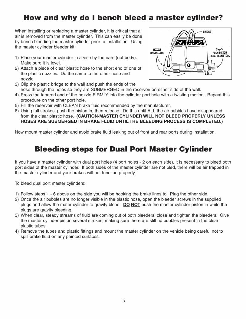
How and why do I bench bleed a master cylinder?
When installing or replacing a master cylinder, it is critical that allair is removed from the master cylinder. This can easily be doneby bench bleeding the master cylinder prior to installation. Usingthe master cylinder bleeder kit:
1) Place your master cylinder in a vise by the ears (not body).Make sure it is level.
2) Attach a piece of clear plastic hose to the short end of one ofthe plastic nozzles. Do the same to the other hose andnozzle.
3) Clip the plastic bridge to the wall and push the ends of thehose through the holes so they are SUBMERGED in the reservoir on either side of the wall.
4) Press the tapered end of the nozzle FIRMLY into the cylinder port hole with a twisting motion. Repeat thisprocedure on the other port hole.
5) Fill the reservoir with CLEAN brake fluid recommended by the manufacturer.6) Using full strokes, push the piston in, then release. Do this until ALL the air bubbles have disappeared
from the clear plastic hose. (CAUTION-MASTER CYLINDER WILL NOT BLEED PROPERLY UNLESSHOSES ARE SUBMERGED IN BRAKE FLUID UNTIL THE BLEEDING PROCESS IS COMPLETED.)
Now mount master cylinder and avoid brake fluid leaking out of front and rear ports during installation.
Bleeding steps for Dual Port Master Cylinder
If you have a master cylinder with dual port holes (4 port holes - 2 on each side), it is necessary to bleed bothport sides of the master cylinder. If both sides of the master cylinder are not bled, there will be air trapped inthe master cylinder and your brakes will not function properly.
To bleed dual port master cylinders:
1) Follow steps 1 - 6 above on the side you will be hooking the brake lines to. Plug the other side.2) Once the air bubbles are no longer visible in the plastic hose, open the bleeder screws in the supplied
plugs and allow the mater cylinder to gravity bleed. DO NOT push the master cylinder piston in while theplugs are gravity bleeding.
3) When clear, steady streams of fluid are coming out of both bleeders, close and tighten the bleeders. Givethe master cylinder piston several strokes, making sure there are still no bubbles present in the clearplastic tubes.
4) Remove the tubes and plastic fittings and mount the master cylinder on the vehicle being careful not tospill brake fluid on any painted surfaces.

![THIS BRACKET IS WRESTLING A ROUND ROBIN …usawct.org/results/2007-2008/middletownresults[1].pdfTHIS BRACKET IS WRESTLING A ROUND ROBIN FORMAT THIRD PLACE Elijah Meinhard ... Aidan](https://img.pdfslide.net/doc/110x75/5aacdd867f8b9a8d678d6c82/this-bracket-is-wrestling-a-round-robin-1pdfthis-bracket-is-wrestling-a-round.jpg)