Embed Size (px)
Citation preview
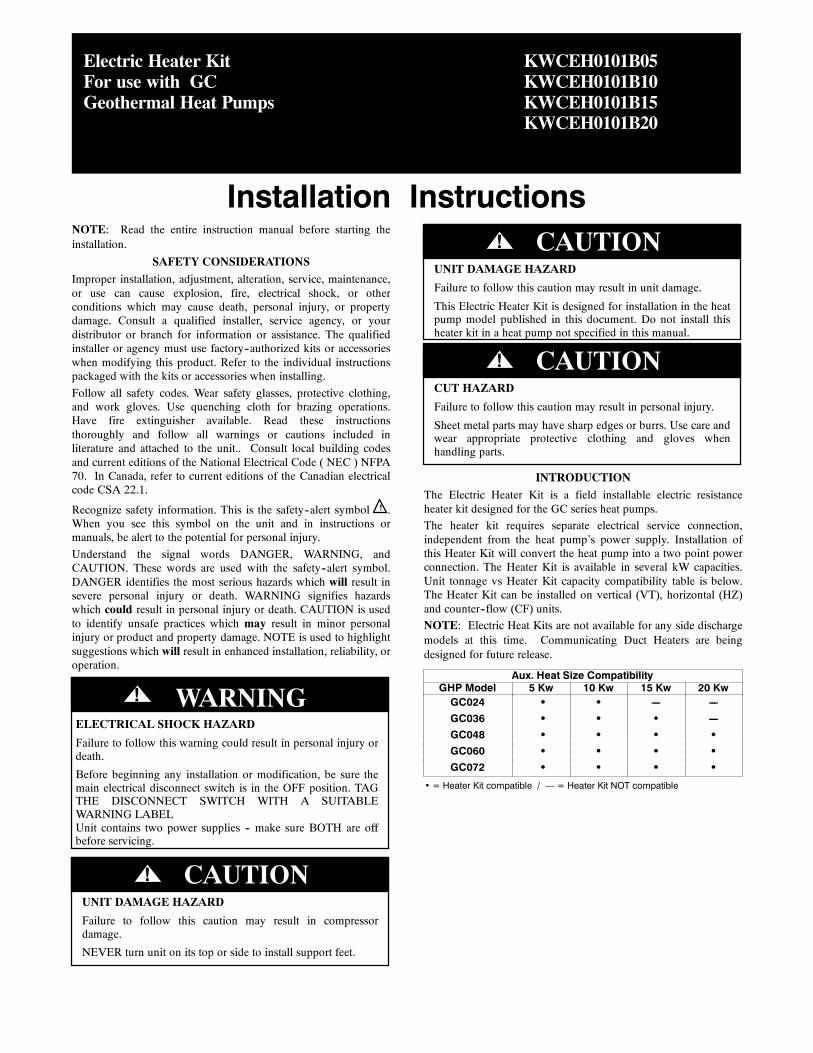
Electric Heater KitFor use with GCGeothermal Heat Pumps
Installation Instructions
KWCEH0101B05KWCEH0101B10KWCEH0101B15KWCEH0101B20
NOTE: Read the entire instruction manual before starting theinstallation.
SAFETY CONSIDERATIONSImproper installation, adjustment, alteration, service, maintenance,or use can cause explosion, fire, electrical shock, or otherconditions which may cause death, personal injury, or propertydamage. Consult a qualified installer, service agency, or yourdistributor or branch for information or assistance. The qualifiedinstaller or agency must use factory--authorized kits or accessorieswhen modifying this product. Refer to the individual instructionspackaged with the kits or accessories when installing.Follow all safety codes. Wear safety glasses, protective clothing,and work gloves. Use quenching cloth for brazing operations.Have fire extinguisher available. Read these instructionsthoroughly and follow all warnings or cautions included inliterature and attached to the unit.. Consult local building codesand current editions of the National Electrical Code ( NEC ) NFPA70. In Canada, refer to current editions of the Canadian electricalcode CSA 22.1.
Recognize safety information. This is the safety--alert symbol !! .When you see this symbol on the unit and in instructions ormanuals, be alert to the potential for personal injury.Understand the signal words DANGER, WARNING, andCAUTION. These words are used with the safety--alert symbol.DANGER identifies the most serious hazards which will result insevere personal injury or death. WARNING signifies hazardswhich could result in personal injury or death. CAUTION is usedto identify unsafe practices which may result in minor personalinjury or product and property damage. NOTE is used to highlightsuggestions which will result in enhanced installation, reliability, oroperation.
ELECTRICAL SHOCK HAZARD
Failure to follow this warning could result in personal injury ordeath.
Before beginning any installation or modification, be sure themain electrical disconnect switch is in the OFF position. TAGTHE DISCONNECT SWITCH WITH A SUITABLEWARNING LABELUnit contains two power supplies -- make sure BOTH are offbefore servicing.
! WARNING
UNIT DAMAGE HAZARD
Failure to follow this caution may result in compressordamage.
NEVER turn unit on its top or side to install support feet.
CAUTION!
UNIT DAMAGE HAZARD
Failure to follow this caution may result in unit damage.
This Electric Heater Kit is designed for installation in the heatpump model published in this document. Do not install thisheater kit in a heat pump not specified in this manual.
CAUTION!
CUT HAZARD
Failure to follow this caution may result in personal injury.
Sheet metal parts may have sharp edges or burrs. Use care andwear appropriate protective clothing and gloves whenhandling parts.
CAUTION!
INTRODUCTIONThe Electric Heater Kit is a field installable electric resistanceheater kit designed for the GC series heat pumps.The heater kit requires separate electrical service connection,independent from the heat pump’s power supply. Installation ofthis Heater Kit will convert the heat pump into a two point powerconnection. The Heater Kit is available in several kW capacities.Unit tonnage vs Heater Kit capacity compatibility table is below.The Heater Kit can be installed on vertical (VT), horizontal (HZ)and counter--flow (CF) units.NOTE: Electric Heat Kits are not available for any side dischargemodels at this time. Communicating Duct Heaters are beingdesigned for future release.
Aux. Heat Size CompatibilityGHP Model 5 Kw 10 Kw 15 Kw 20 KwGC024 • • --- ---GC036 • • • ---GC048 • • • •GC060 • • • •GC072 • • • •
• = Heater Kit compatible / — = Heater Kit NOT compatible
2
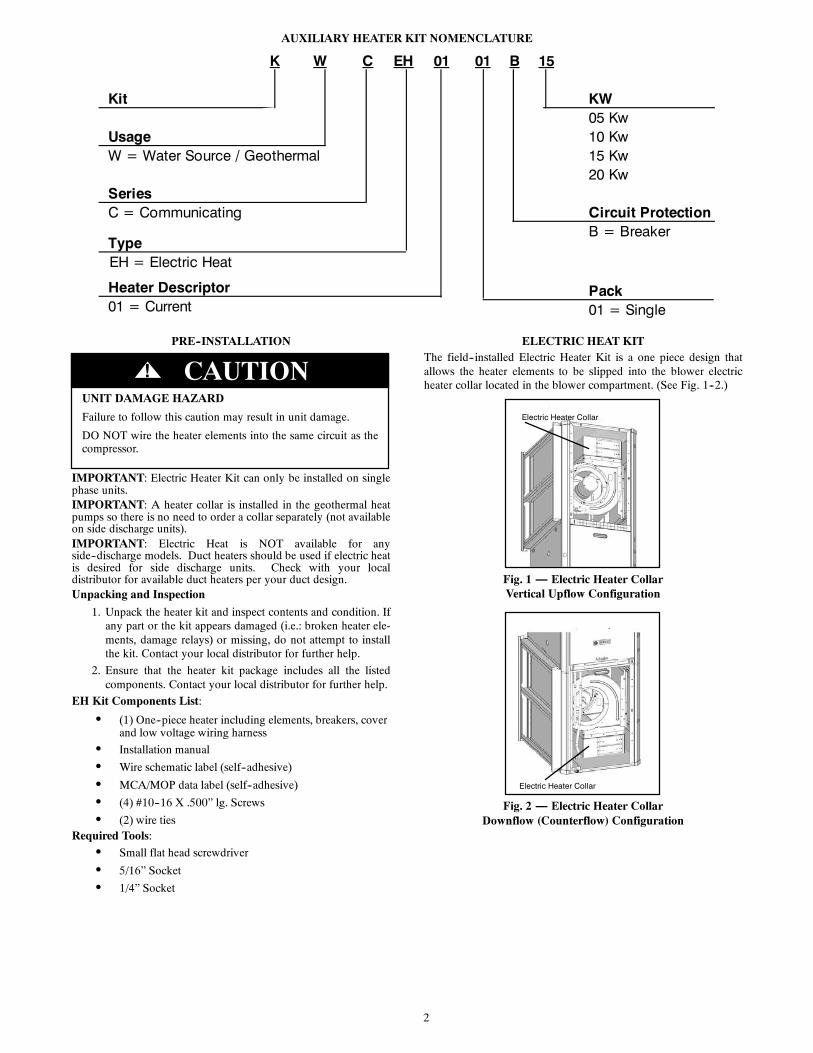
AUXILIARY HEATER KIT NOMENCLATURE
K W EH B
Kit KW05 Kw
Usage 10 KwW = Water Source / Geothermal 15 Kw
20 KwSeriesC = Communicating Circuit Protection
B = BreakerTypeEH = Electric Heat
Pack01 = Single
Heater Descriptor01 = Current
C 01 01 15
PRE--INSTALLATION
UNIT DAMAGE HAZARD
Failure to follow this caution may result in unit damage.
DO NOT wire the heater elements into the same circuit as thecompressor.
CAUTION!
IMPORTANT: Electric Heater Kit can only be installed on singlephase units.IMPORTANT: A heater collar is installed in the geothermal heatpumps so there is no need to order a collar separately (not availableon side discharge units).IMPORTANT: Electric Heat is NOT available for anyside--discharge models. Duct heaters should be used if electric heatis desired for side discharge units. Check with your localdistributor for available duct heaters per your duct design.Unpacking and Inspection
1. Unpack the heater kit and inspect contents and condition. Ifany part or the kit appears damaged (i.e.: broken heater ele-ments, damage relays) or missing, do not attempt to installthe kit. Contact your local distributor for further help.
2. Ensure that the heater kit package includes all the listedcomponents. Contact your local distributor for further help.
EH Kit Components List:
S (1) One--piece heater including elements, breakers, coverand low voltage wiring harness
S Installation manual
S Wire schematic label (self--adhesive)
S MCA/MOP data label (self--adhesive)
S (4) #10--16 X .500” lg. Screws
S (2) wire tiesRequired Tools:
S Small flat head screwdriver
S 5/16” Socket
S 1/4” Socket
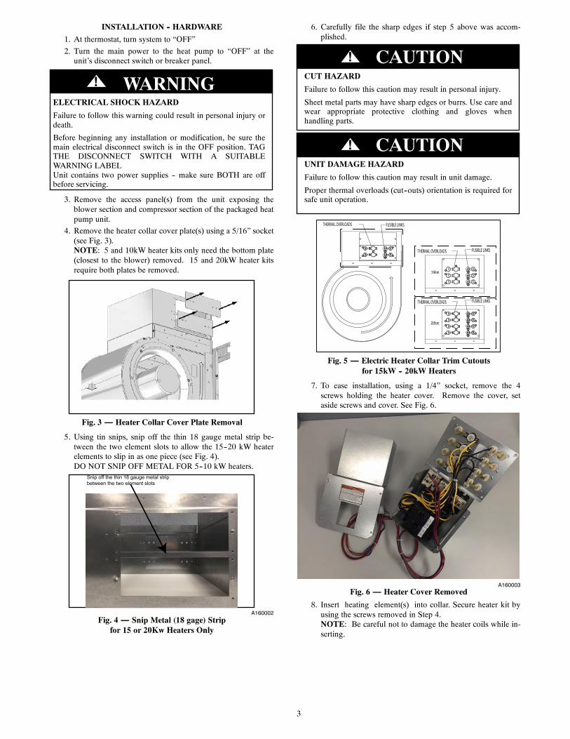
ELECTRIC HEAT KITThe field--installed Electric Heater Kit is a one piece design thatallows the heater elements to be slipped into the blower electricheater collar located in the blower compartment. (See Fig. 1--2.)
Electric Heater Collar
Fig. 1 — Electric Heater CollarVertical Upflow Configuration
Electric Heater Collar
Fig. 2 — Electric Heater CollarDownflow (Counterflow) Configuration
3
INSTALLATION -- HARDWARE1. At thermostat, turn system to “OFF”2. Turn the main power to the heat pump to “OFF” at theunit’s disconnect switch or breaker panel.
ELECTRICAL SHOCK HAZARD
Failure to follow this warning could result in personal injury ordeath.
Before beginning any installation or modification, be sure themain electrical disconnect switch is in the OFF position. TAGTHE DISCONNECT SWITCH WITH A SUITABLEWARNING LABELUnit contains two power supplies -- make sure BOTH are offbefore servicing.
! WARNING
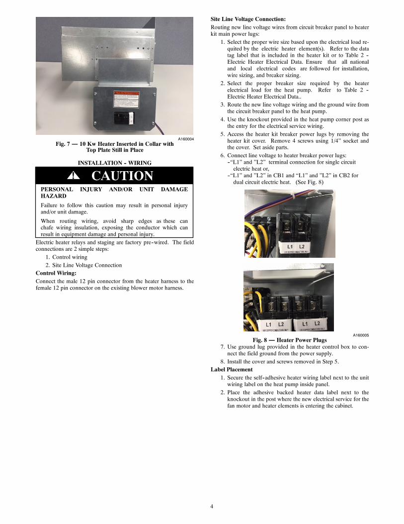
3. Remove the access panel(s) from the unit exposing theblower section and compressor section of the packaged heatpump unit.
4. Remove the heater collar cover plate(s) using a 5/16” socket(see Fig. 3).NOTE: 5 and 10kW heater kits only need the bottom plate(closest to the blower) removed. 15 and 20kW heater kitsrequire both plates be removed.
Fig. 3 — Heater Collar Cover Plate Removal
5. Using tin snips, snip off the thin 18 gauge metal strip be-tween the two element slots to allow the 15--20 kW heaterelements to slip in as one piece (see Fig. 4).DO NOT SNIP OFF METAL FOR 5--10 kW heaters.
Snip off the thin 18 gauge metal strip between the two element slots
A160002Fig. 4 — Snip Metal (18 gage) Strip
for 15 or 20Kw Heaters Only
6. Carefully file the sharp edges if step 5 above was accom-plished.
CUT HAZARD
Failure to follow this caution may result in personal injury.
Sheet metal parts may have sharp edges or burrs. Use care andwear appropriate protective clothing and gloves whenhandling parts.
CAUTION!
UNIT DAMAGE HAZARD
Failure to follow this caution may result in unit damage.
Proper thermal overloads (cut--outs) orientation is required forsafe unit operation.
CAUTION!
20kw
15kw
THERMAL OVERLOADS FUSIBLE LINKS
THERMAL OVERLOADS FUSIBLE LINKS
THERMAL OVERLOADS FUSIBLE LINKS
Fig. 5 — Electric Heater Collar Trim Cutoutsfor 15kW -- 20kW Heaters
7. To ease installation, using a 1/4” socket, remove the 4screws holding the heater cover. Remove the cover, setaside screws and cover. See Fig. 6.
A160003Fig. 6 — Heater Cover Removed
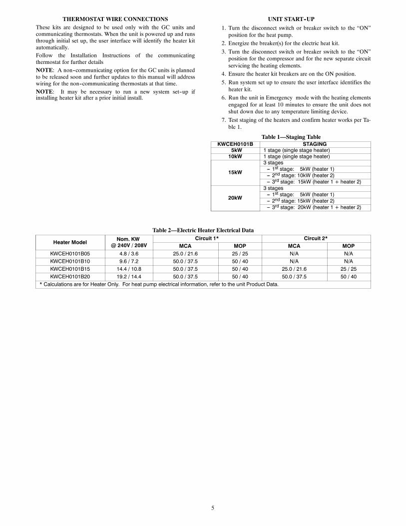
8. Insert heating element(s) into collar. Secure heater kit byusing the screws removed in Step 4.NOTE: Be careful not to damage the heater coils while in-serting.
4
A160004Fig. 7 — 10 Kw Heater Inserted in Collar with
Top Plate Still in Place
INSTALLATION -- WIRING
PERSONAL INJURY AND/OR UNIT DAMAGEHAZARD
Failure to follow this caution may result in personal injuryand/or unit damage.
When routing wiring, avoid sharp edges as these canchafe wiring insulation, exposing the conductor which canresult in equipment damage and personal injury.
CAUTION!
Electric heater relays and staging are factory pre--wired. The fieldconnections are 2 simple steps:
1. Control wiring2. Site Line Voltage Connection
Control Wiring:Connect the male 12 pin connector from the heater harness to thefemale 12 pin connector on the existing blower motor harness.
Site Line Voltage Connection:Routing new line voltage wires from circuit breaker panel to heaterkit main power lugs:
1. Select the proper wire size based upon the electrical load re-quited by the electric heater element(s). Refer to the datatag label that is included in the heater kit or to Table 2 --Electric Heater Electrical Data. Ensure that all nationaland local electrical codes are followed for installation,wire sizing, and breaker sizing.
2. Select the proper breaker size required by the heaterelectrical load for the heat pump. Refer to Table 2 --Electric Heater Electrical Data..
3. Route the new line voltage wiring and the ground wire fromthe circuit breaker panel to the heat pump.
4. Use the knockout provided in the heat pump corner post asthe entry for the electrical service wiring.
5. Access the heater kit breaker power lugs by removing theheater kit cover. Remove 4 screws using 1/4” socket andthe cover. Set aside parts.
6. Connect line voltage to heater breaker power lugs:--“L1” and ”L2” terminal connection for single circuitelectric heat or,
--“L1” and ”L2” in CB1 and “L1” and ”L2” in CB2 fordual circuit electric heat. (See Fig. 8)
A160005Fig. 8 — Heater Power Plugs
7. Use ground lug provided in the heater control box to con-nect the field ground from the power supply.
8. Install the cover and screws removed in Step 5.Label Placement
1. Secure the self--adhesive heater wiring label next to the unitwiring label on the heat pump inside panel.
2. Place the adhesive backed heater data label next to theknockout in the post where the new electrical service for thefan motor and heater elements is entering the cabinet.
5
THERMOSTATWIRE CONNECTIONSThese kits are designed to be used only with the GC units andcommunicating thermostats. When the unit is powered up and runsthrough initial set up, the user interface will identify the heater kitautomatically.Follow the Installation Instructions of the communicatingthermostat for further detailsNOTE: A non--communicating option for the GC units is plannedto be released soon and further updates to this manual will addresswiring for the non--communicating thermostats at that time.NOTE: It may be necessary to run a new system set--up ifinstalling heater kit after a prior initial install.
UNIT START--UP1. Turn the disconnect switch or breaker switch to the “ON”position for the heat pump.
2. Energize the breaker(s) for the electric heat kit.3. Turn the disconnect switch or breaker switch to the “ON”position for the compressor and for the new separate circuitservicing the heating elements.
4. Ensure the heater kit breakers are on the ON position.5. Run system set up to ensure the user interface identifies theheater kit.
6. Run the unit in Emergency mode with the heating elementsengaged for at least 10 minutes to ensure the unit does notshut down due to any temperature limiting device.
7. Test staging of the heaters and confirm heater works per Ta-ble 1.
Table 1—Staging TableKWCEH0101B STAGING
5kW 1 stage (single stage heater)10kW 1 stage (single stage heater)
15kW
3 stages--- 1st stage: 5kW (heater 1)--- 2nd stage: 10kW (heater 2)--- 3rd stage: 15kW (heater 1 + heater 2)
20kW
3 stages--- 1st stage: 5kW (heater 1)--- 2nd stage: 15kW (heater 2)--- 3rd stage: 20kW (heater 1 + heater 2)
Table 2—Electric Heater Electrical Data
Heater ModelNom. KW
@ 240V / 208VCircuit 1* Circuit 2*
MCA MOP MCA MOPKWCEH0101B05 4.8 / 3.6 25.0 / 21.6 25 / 25 N/A N/AKWCEH0101B10 9.6 / 7.2 50.0 / 37.5 50 / 40 N/A N/AKWCEH0101B15 14.4 / 10.8 50.0 / 37.5 50 / 40 25.0 / 21.6 25 / 25KWCEH0101B20 19.2 / 14.4 50.0 / 37.5 50 / 40 50.0 / 37.5 50 / 40
* Calculations are for Heater Only. For heat pump electrical information, refer to the unit Product Data.
6
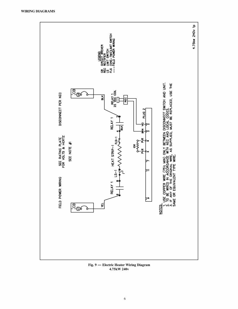
WIRING DIAGRAMS
Fig. 9 — Electric Heater Wiring Diagram4.75kW 240v
7
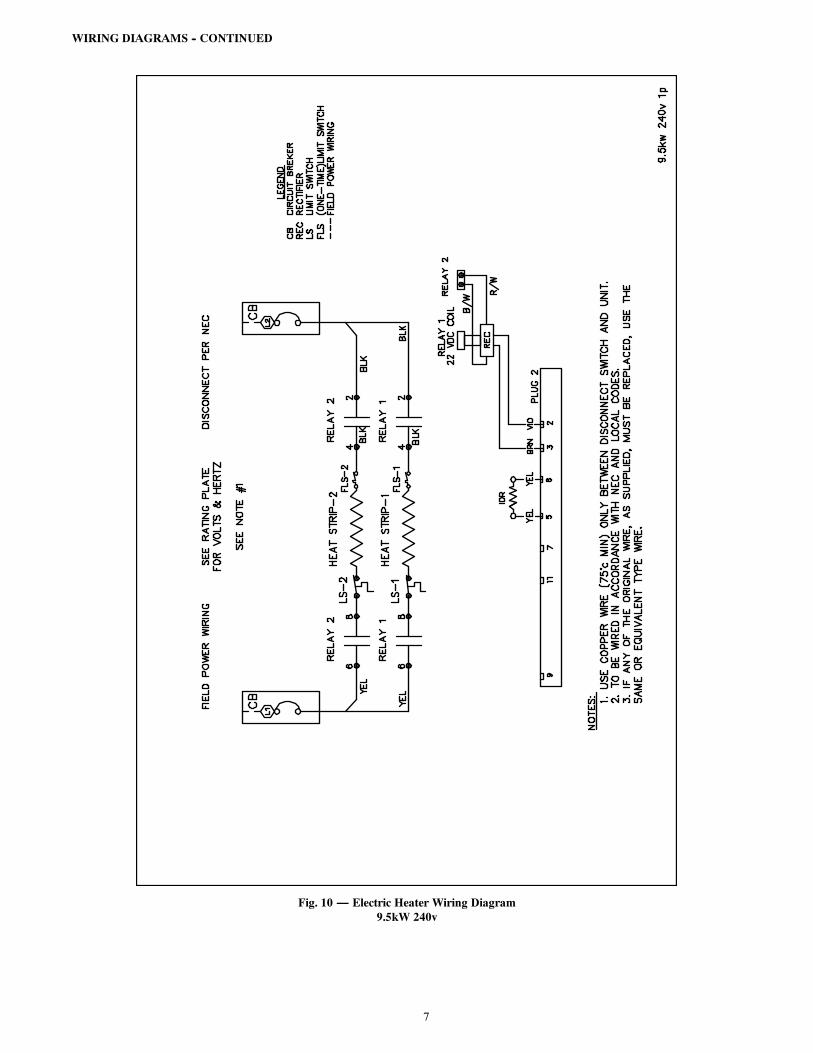
WIRING DIAGRAMS -- CONTINUED
Fig. 10 — Electric Heater Wiring Diagram9.5kW 240v
8
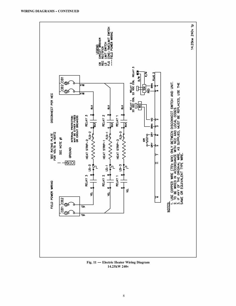
WIRING DIAGRAMS -- CONTINUED
Fig. 11 — Electric Heater Wiring Diagram14.25kW 240v
9
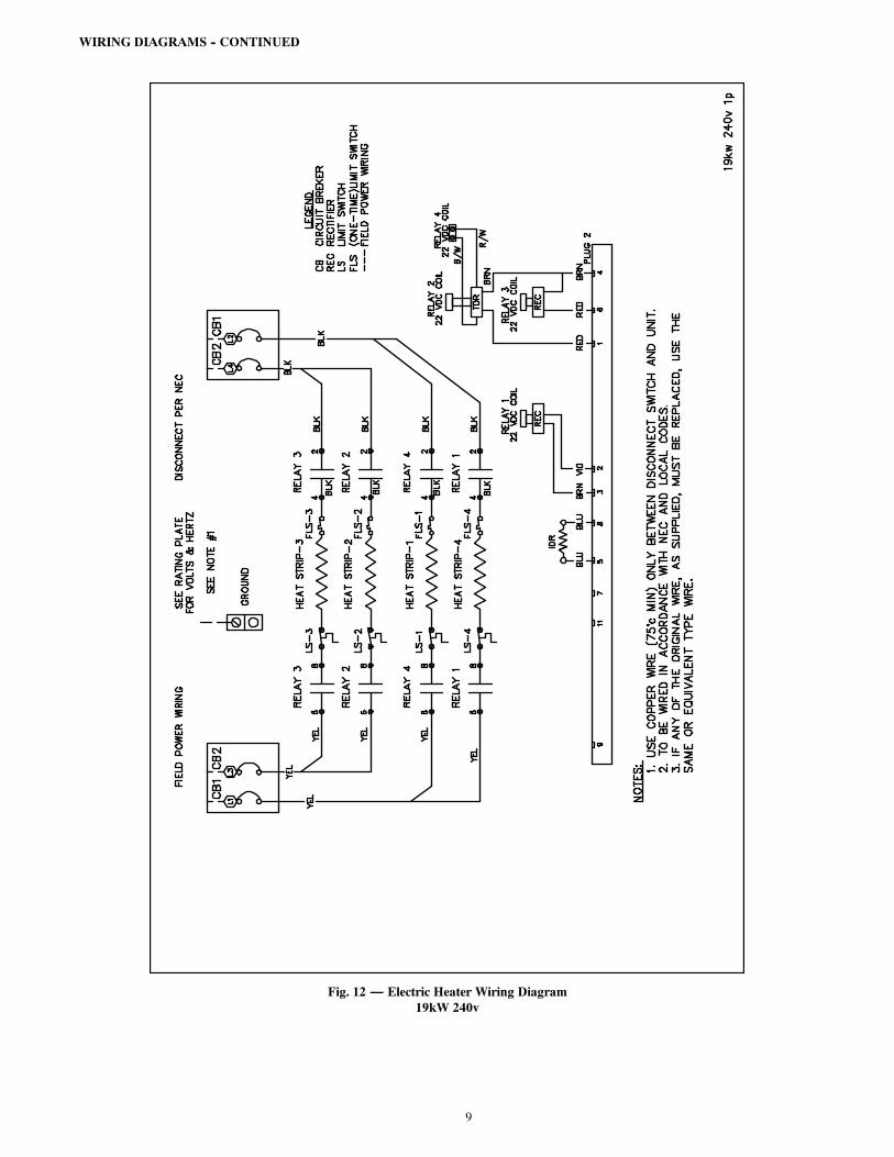
WIRING DIAGRAMS -- CONTINUED
Fig. 12 — Electric Heater Wiring Diagram19kW 240v
10
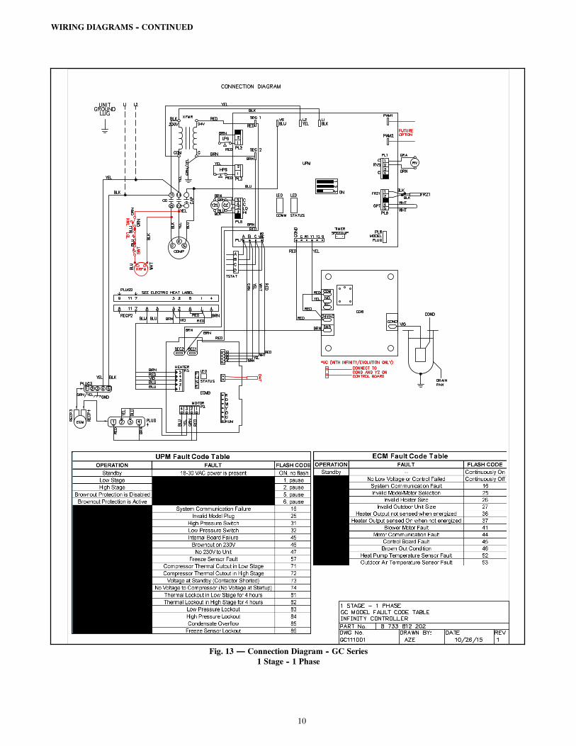
WIRING DIAGRAMS -- CONTINUED
Fig. 13 — Connection Diagram -- GC Series1 Stage -- 1 Phase
11
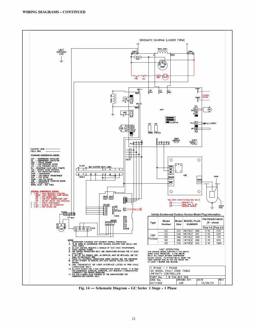
WIRING DIAGRAMS -- CONTINUED
Fig. 14 — Schematic Diagram -- GC Series 1 Stage -- 1 Phase

12
FHP
Copyright 2016 CAC / BDP S 7310 W. Morris St. S Indianapolis, IN 46231
Manufacturer reserves the right to change, at any time, specifications and designs without notice and without obligations.
Catalog No: IIK--KWCEH--01Replaces: New
Edition Date: 01/16