Embed Size (px)
Citation preview
516 01 2502 02 09−14−10
PACKAGED HEAT PUMP UNITS
Installation InstructionsPH4E Series
400V−3Ph−50Hz
International Comfort Products, LLCLewisburg, TN. 37091
TABLE OF CONTENTSPAGE
SAFETY CONSIDERATIONS 2. . . . . . . . . . . . . . . . . . . . . . . . . . . . . . .INTRODUCTION 2. . . . . . . . . . . . . . . . . . . . . . . . . . . . . . . . . . . . . . . . . .RECEIVING AND INSTALLATION 2. . . . . . . . . . . . . . . . . . . . . . . . . . .Check Equipment 2. . . . . . . . . . . . . . . . . . . . . . . . . . . . . . . . . . . . . . . .
Identify Unit 2. . . . . . . . . . . . . . . . . . . . . . . . . . . . . . . . . . . . . . . . . . . .Inspect Shipment 2. . . . . . . . . . . . . . . . . . . . . . . . . . . . . . . . . . . . . . .
Provide Unit Support 2. . . . . . . . . . . . . . . . . . . . . . . . . . . . . . . . . . . . . .Roof Curb 2. . . . . . . . . . . . . . . . . . . . . . . . . . . . . . . . . . . . . . . . . . . . .Slab Mount 3. . . . . . . . . . . . . . . . . . . . . . . . . . . . . . . . . . . . . . . . . . . .
Provide Clearances 3. . . . . . . . . . . . . . . . . . . . . . . . . . . . . . . . . . . . . . .Rig and Place Unit 3. . . . . . . . . . . . . . . . . . . . . . . . . . . . . . . . . . . . . . . .
Inspection 3. . . . . . . . . . . . . . . . . . . . . . . . . . . . . . . . . . . . . . . . . . . . .Rigging/Lifting of Unit 7. . . . . . . . . . . . . . . . . . . . . . . . . . . . . . . . . . .
Select and Install Ductwork 7. . . . . . . . . . . . . . . . . . . . . . . . . . . . . . . .Converting Horizontal Discharge Units to Downflow(Vertical) Discharge Units 8. . . . . . . . . . . . . . . . . . . . . . . . . . . . . . . .
Provide for Condensate Disposal 8. . . . . . . . . . . . . . . . . . . . . . . . . . .Install Electrical Connections 9. . . . . . . . . . . . . . . . . . . . . . . . . . . . . . .
High−Voltage Connections 9. . . . . . . . . . . . . . . . . . . . . . . . . . . . . . .Control Voltage Connections 10. . . . . . . . . . . . . . . . . . . . . . . . . . . .Standard Connections 10. . . . . . . . . . . . . . . . . . . . . . . . . . . . . . . . . .Transformer Protection 10. . . . . . . . . . . . . . . . . . . . . . . . . . . . . . . . .Special Procedures for 420−v Operations 10. . . . . . . . . . . . . . . . .Accessory Electric heaters Installation 10. . . . . . . . . . . . . . . . . . . .Sequence of Operation 10. . . . . . . . . . . . . . . . . . . . . . . . . . . . . . . . .
PRE−START−UP 13. . . . . . . . . . . . . . . . . . . . . . . . . . . . . . . . . . . . . . . . .START−UP 13. . . . . . . . . . . . . . . . . . . . . . . . . . . . . . . . . . . . . . . . . . . . . .
Checking Cooling & Heating Control Operation 13. . . . . . . . . . . . Check for Refrigerant Leaks 13. . . . . . . . . . . . . . . . . . . . . . . . . . . . .
PAGEStart−Up Adjustments 13. . . . . . . . . . . . . . . . . . . . . . . . . . . . . .
Checking & Adjusting Refrigerant Charge 14. . . . . . . . . . .Indoor Airflow & Airflow Adjustments 15. . . . . . . . . . . . . . .
Defrost Control 16. . . . . . . . . . . . . . . . . . . . . . . . . . . . . . . . . . . . .Quiet Shift 16. . . . . . . . . . . . . . . . . . . . . . . . . . . . . . . . . . . . . .Defrost 17. . . . . . . . . . . . . . . . . . . . . . . . . . . . . . . . . . . . . . . . .
MAINTENANCE 17. . . . . . . . . . . . . . . . . . . . . . . . . . . . . . . . . . .Air Filter 17. . . . . . . . . . . . . . . . . . . . . . . . . . . . . . . . . . . . . . . . . . .Indoor Blower and Motor 17. . . . . . . . . . . . . . . . . . . . . . . . . . . .Outdoor Coil, Indoor Coil, & Condensate Drain Pan 18. . . . .Outdoor Fan 18. . . . . . . . . . . . . . . . . . . . . . . . . . . . . . . . . . . . . . .Electrical Controls and Wiring 18. . . . . . . . . . . . . . . . . . . . . . . .Refrigerant Circuit 19. . . . . . . . . . . . . . . . . . . . . . . . . . . . . . . . . .Indoor Airflow 19. . . . . . . . . . . . . . . . . . . . . . . . . . . . . . . . . . . . . .Metering Devices− Piston 19. . . . . . . . . . . . . . . . . . . . . . . . . . .Pressure Switches 20. . . . . . . . . . . . . . . . . . . . . . . . . . . . . . . . . .Loss of Charge Switch 20. . . . . . . . . . . . . . . . . . . . . . . . . . . . . .High Pressure Switch 20. . . . . . . . . . . . . . . . . . . . . . . . . . . . . . .Copeland Scroll compressor (R−410A Refrigerant) 20. . . . . .Refrigerant System 20. . . . . . . . . . . . . . . . . . . . . . . . . . . . . . . . .
Refrigerant 20. . . . . . . . . . . . . . . . . . . . . . . . . . . . . . . . . . . . .Compressor Oil 20. . . . . . . . . . . . . . . . . . . . . . . . . . . . . . . . .Servicing Systems on Roofs with Synthetic Materials 20.Liquid Line Filter Drier 20. . . . . . . . . . . . . . . . . . . . . . . . . . . .R−410A Refrigerant Charging 20. . . . . . . . . . . . . . . . . . . . .
System Information 21. . . . . . . . . . . . . . . . . . . . . . . . . . . . . . . . .Loss of Charge Switch 21. . . . . . . . . . . . . . . . . . . . . . . . . . .Check Defrost Thermostat 21. . . . . . . . . . . . . . . . . . . . . . . .
TROUBLESHOOTING 23. . . . . . . . . . . . . . . . . . . . . . . . . . . . . .START−UP CHECKLIST 24. . . . . . . . . . . . . . . . . . . . . . . . . . . .
2 513 01 3402 02
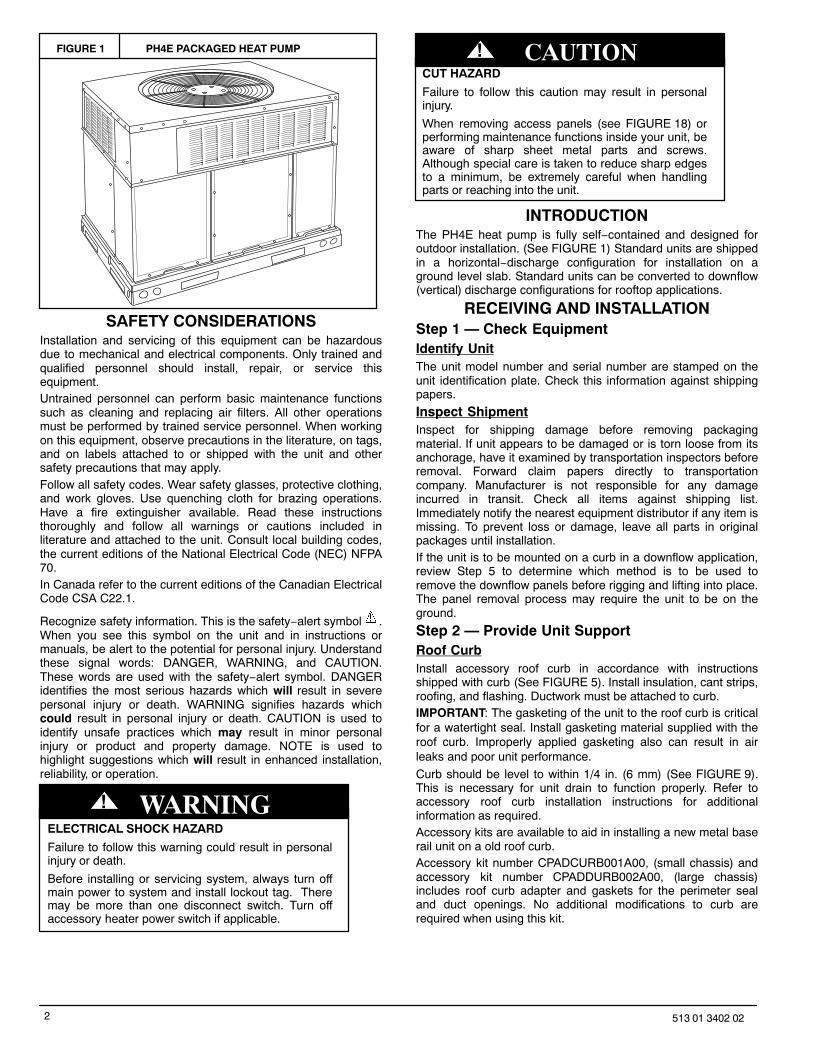
FIGURE 1 PH4E PACKAGED HEAT PUMP
SAFETY CONSIDERATIONSInstallation and servicing of this equipment can be hazardousdue to mechanical and electrical components. Only trained andqualified personnel should install, repair, or service thisequipment.Untrained personnel can perform basic maintenance functionssuch as cleaning and replacing air filters. All other operationsmust be performed by trained service personnel. When workingon this equipment, observe precautions in the literature, on tags,and on labels attached to or shipped with the unit and othersafety precautions that may apply.Follow all safety codes. Wear safety glasses, protective clothing,and work gloves. Use quenching cloth for brazing operations.Have a fire extinguisher available. Read these instructionsthoroughly and follow all warnings or cautions included inliterature and attached to the unit. Consult local building codes,the current editions of the National Electrical Code (NEC) NFPA70.In Canada refer to the current editions of the Canadian ElectricalCode CSA C22.1.
Recognize safety information. This is the safety−alert symbol .When you see this symbol on the unit and in instructions ormanuals, be alert to the potential for personal injury. Understandthese signal words: DANGER, WARNING, and CAUTION.These words are used with the safety−alert symbol. DANGERidentifies the most serious hazards which will result in severepersonal injury or death. WARNING signifies hazards whichcould result in personal injury or death. CAUTION is used toidentify unsafe practices which may result in minor personalinjury or product and property damage. NOTE is used tohighlight suggestions which will result in enhanced installation,reliability, or operation.
ELECTRICAL SHOCK HAZARD
Failure to follow this warning could result in personalinjury or death.
Before installing or servicing system, always turn offmain power to system and install lockout tag. Theremay be more than one disconnect switch. Turn offaccessory heater power switch if applicable.
! WARNING
CUT HAZARD
Failure to follow this caution may result in personalinjury.
When removing access panels (see FIGURE 18) orperforming maintenance functions inside your unit, beaware of sharp sheet metal parts and screws.Although special care is taken to reduce sharp edgesto a minimum, be extremely careful when handlingparts or reaching into the unit.
! CAUTION
INTRODUCTIONThe PH4E heat pump is fully self−contained and designed foroutdoor installation. (See FIGURE 1) Standard units are shippedin a horizontal−discharge configuration for installation on aground level slab. Standard units can be converted to downflow(vertical) discharge configurations for rooftop applications.
RECEIVING AND INSTALLATIONStep 1 — Check EquipmentIdentify UnitThe unit model number and serial number are stamped on theunit identification plate. Check this information against shippingpapers.
Inspect ShipmentInspect for shipping damage before removing packagingmaterial. If unit appears to be damaged or is torn loose from itsanchorage, have it examined by transportation inspectors beforeremoval. Forward claim papers directly to transportationcompany. Manufacturer is not responsible for any damageincurred in transit. Check all items against shipping list.Immediately notify the nearest equipment distributor if any item ismissing. To prevent loss or damage, leave all parts in originalpackages until installation.If the unit is to be mounted on a curb in a downflow application,review Step 5 to determine which method is to be used toremove the downflow panels before rigging and lifting into place.The panel removal process may require the unit to be on theground.
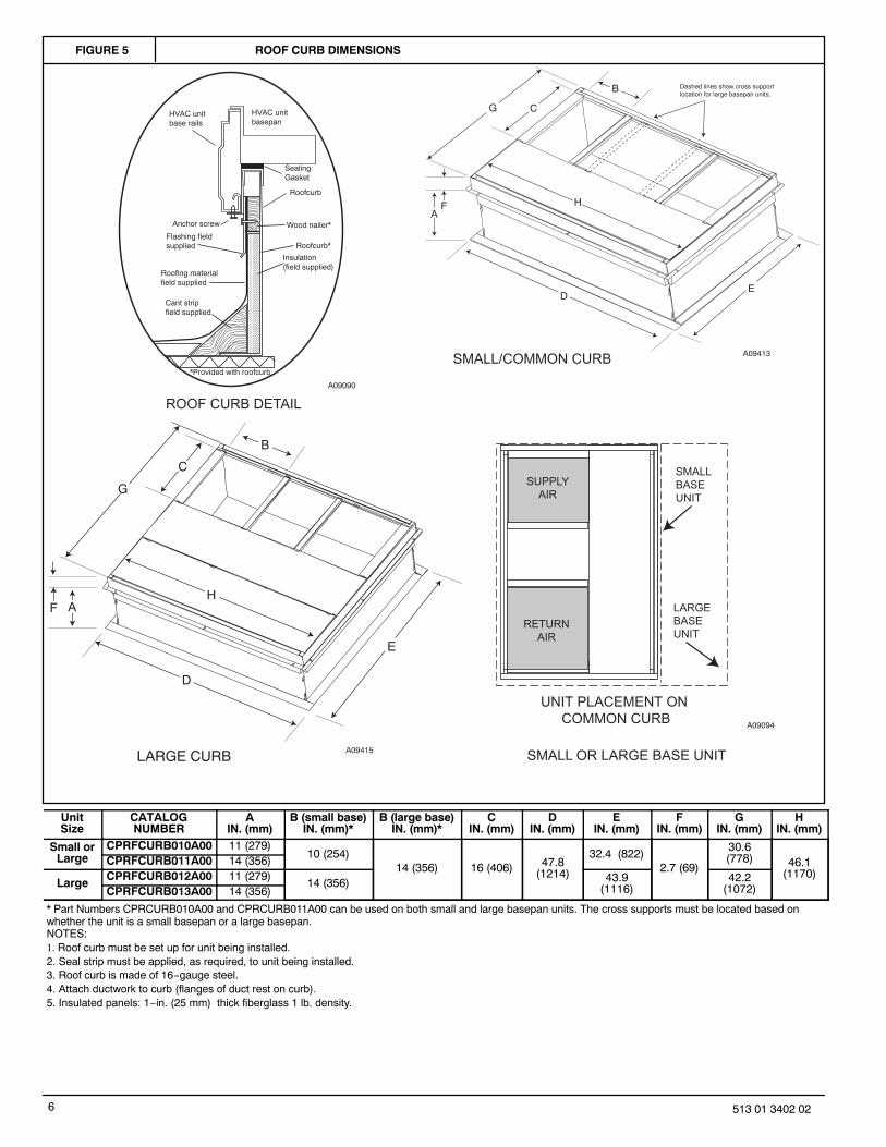
Step 2 — Provide Unit SupportRoof CurbInstall accessory roof curb in accordance with instructionsshipped with curb (See FIGURE 5). Install insulation, cant strips,roofing, and flashing. Ductwork must be attached to curb.IMPORTANT: The gasketing of the unit to the roof curb is criticalfor a watertight seal. Install gasketing material supplied with theroof curb. Improperly applied gasketing also can result in airleaks and poor unit performance.
Curb should be level to within 1/4 in. (6 mm) (See FIGURE 9).This is necessary for unit drain to function properly. Refer toaccessory roof curb installation instructions for additionalinformation as required.Accessory kits are available to aid in installing a new metal baserail unit on a old roof curb.Accessory kit number CPADCURB001A00, (small chassis) andaccessory kit number CPADDURB002A00, (large chassis)includes roof curb adapter and gaskets for the perimeter sealand duct openings. No additional modifications to curb arerequired when using this kit.
3513 01 3402 02
UNIT STRUCTURAL DAMAGE HAZARD
Failure to follow this caution may result in propertydamage
Ensure there is sufficient clearance for saw bladewhen cutting the outer horizontal flange of the roofcurb so there is no damage to the roof or flashing.
CAUTION!
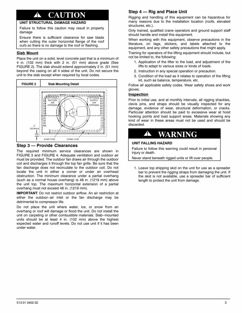
Slab MountPlace the unit on a solid, level concrete pad that is a minimum of4 in. (102 mm) thick with 2 in. (51 mm) above grade (SeeFIGURE 2). The slab should extend approximately 2 in. (51 mm)beyond the casing on all 4 sides of the unit. Do not secure theunit to the slab except when required by local codes.
FIGURE 2 Slab Mounting Detail
OPTIONALRETURN
AIROPENING
OPTIONALSUPPLY
AIROPENING
EVAP. COIL COND. COIL
2˝(50.8mm)
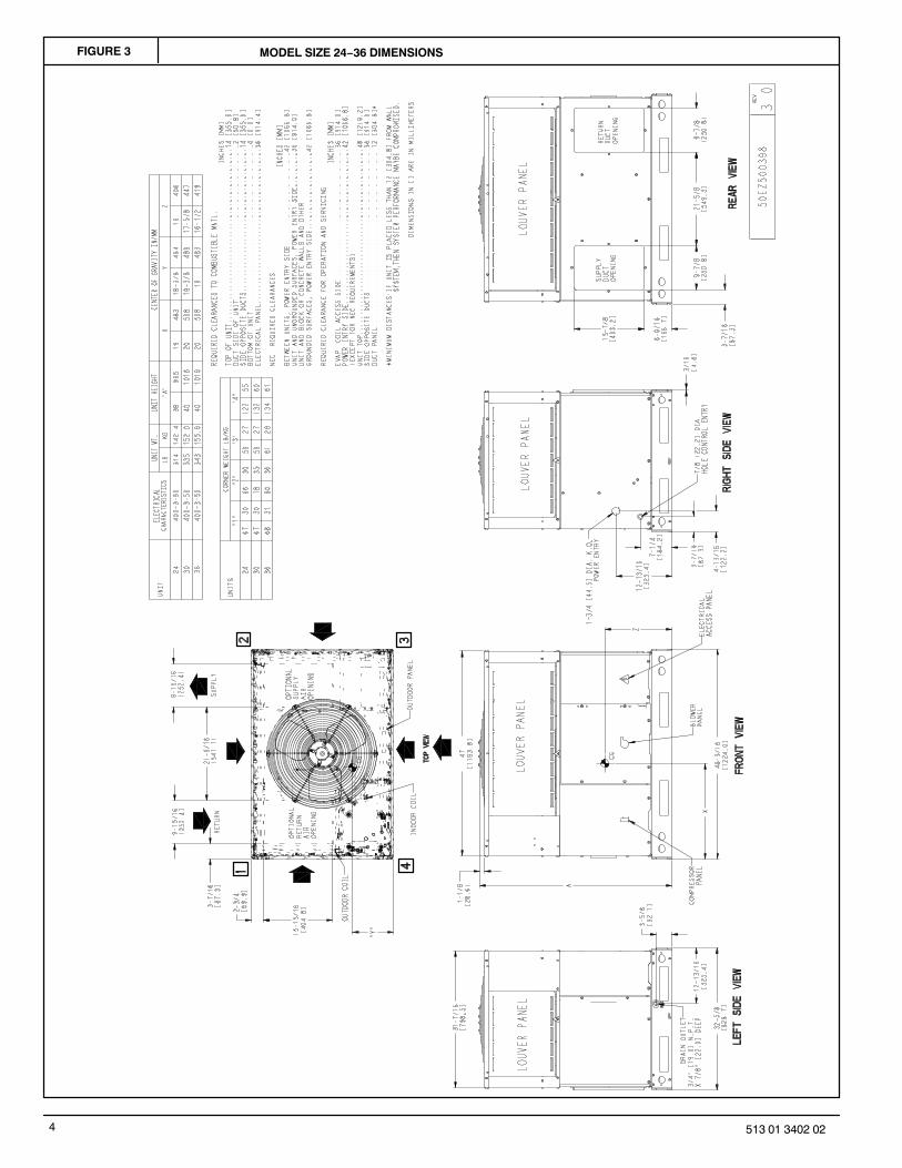
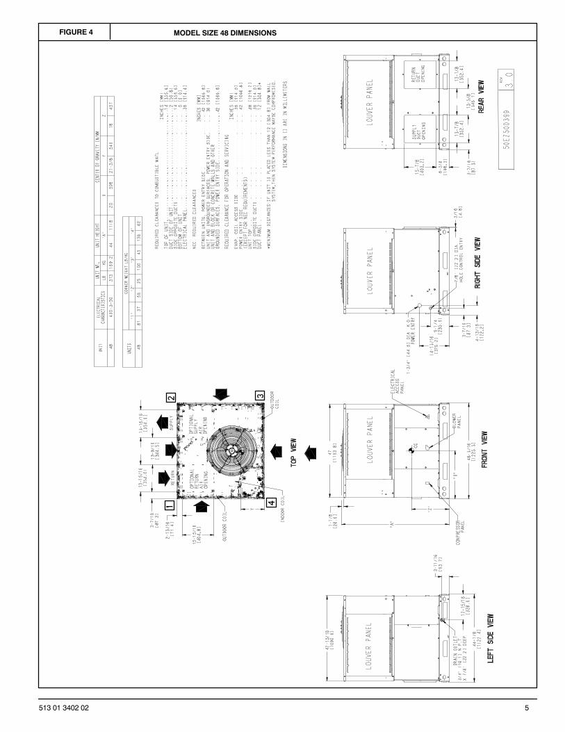
Step 3 — Provide ClearancesThe required minimum service clearances are shown inFIGURE 3 and FIGURE 4. Adequate ventilation and outdoor airmust be provided. The outdoor fan draws air through the outdoorcoil and discharges it through the top fan grille. Be sure that thefan discharge does not recirculate to the outdoor coil. Do notlocate the unit in either a corner or under an overheadobstruction. The minimum clearance under a partial overhang(such as a normal house overhang) is 48 in. (1219 mm) abovethe unit top. The maximum horizontal extension of a partialoverhang must not exceed 48 in. (1219 mm).IMPORTANT: Do not restrict outdoor airflow. An air restriction ateither the outdoor−air inlet or the fan discharge may bedetrimental to compressor life.Do not place the unit where water, ice, or snow from anoverhang or roof will damage or flood the unit. Do not install theunit on carpeting or other combustible materials. Slab−mountedunits should be at least 4 in. (102 mm) above the highestexpected water and runoff levels. Do not use unit if it has beenunder water.
Step 4 — Rig and Place UnitRigging and handling of this equipment can be hazardous formany reasons due to the installation location (roofs, elevatedstructures, etc.).Only trained, qualified crane operators and ground support staffshould handle and install this equipment.When working with this equipment, observe precautions in theliterature, on tags, stickers, and labels attached to theequipment, and any other safety precautions that might apply.Training for operators of the lifting equipment should include, butnot be limited to, the following:
1. Application of the lifter to the load, and adjustment of thelifts to adapt to various sizes or kinds of loads.
2. Instruction in any special operation or precaution.3. Condition of the load as it relates to operation of the lifting
kit, such as balance, temperature, etc.Follow all applicable safety codes. Wear safety shoes and workgloves.
InspectionPrior to initial use, and at monthly intervals, all rigging shackles,clevis pins, and straps should be visually inspected for anydamage, evidence of wear, structural deformation, or cracks.Particular attention should be paid to excessive wear at hoisthooking points and load support areas. Materials showing anykind of wear in these areas must not be used and should bediscarded.
UNIT FALLING HAZARD
Failure to follow this warning could result in personalinjury or death.
Never stand beneath rigged units or lift over people.
! WARNING
1. Leave top shipping skid on the unit for use as a spreaderbar to prevent the rigging straps from damaging the unit. Ifthe skid is not available, use a spreader bar of sufficientlength to protect the unit from damage.
4 513 01 3402 02
FIGURE 3 MODEL SIZE 24−36 DIMENSIONS
5513 01 3402 02
FIGURE 4 MODEL SIZE 48 DIMENSIONS
6 513 01 3402 02
FIGURE 5 ROOF CURB DIMENSIONS
RETURN AIR
SMALLBASE UNIT
SUPPLYAIR
LARGEBASE UNIT
UNIT PLACEMENT ON COMMON CURB
LARGE CURB SMALL OR LARGE BASE UNIT
SMALL/COMMON CURB
ROOF CURB DETAIL
Wood nailer*
Roofcurb*
Insulation(field supplied)
*Provided with roofcurb
Cant stripfield supplied
Roofing materialfield supplied
Flashing fieldsupplied
HVAC unitbase rails
Roofcurb
SealingGasket
HVAC unitbasepan
Anchor screw
A09090
A09413
A09094
A09415
C
B
AF
DE
Dashed lines show cross supportlocation for large basepan units.
G
H
C
B
AF
D
E
G
H
UnitSize
CATALOGNUMBER
AIN. (mm)
B (small base)IN. (mm)*
B (large base)IN. (mm)*
CIN. (mm)
DIN. (mm)
EIN. (mm)
FIN. (mm)
GIN. (mm)
HIN. (mm)
Small orLarge
CPRFCURB010A00 11 (279)10 (254)
14 (356) 16 (406) 47.8(1214)
32.4 (822)2.7 (69)
30.6(778) 46.1
(1170)CPRFCURB011A00 14 (356)
LargeCPRFCURB012A00 11 (279)
14 (356) 43.9(1116)
42.2(1072)CPRFCURB013A00 14 (356)
* Part Numbers CPRCURB010A00 and CPRCURB011A00 can be used on both small and large basepan units. The cross supports must be located based onwhether the unit is a small basepan or a large basepan.NOTES:1. Roof curb must be set up for unit being installed.2. Seal strip must be applied, as required, to unit being installed.3. Roof curb is made of 16−gauge steel.4. Attach ductwork to curb (flanges of duct rest on curb).5. Insulated panels: 1−in. (25 mm) thick fiberglass 1 lb. density.
7513 01 3402 02
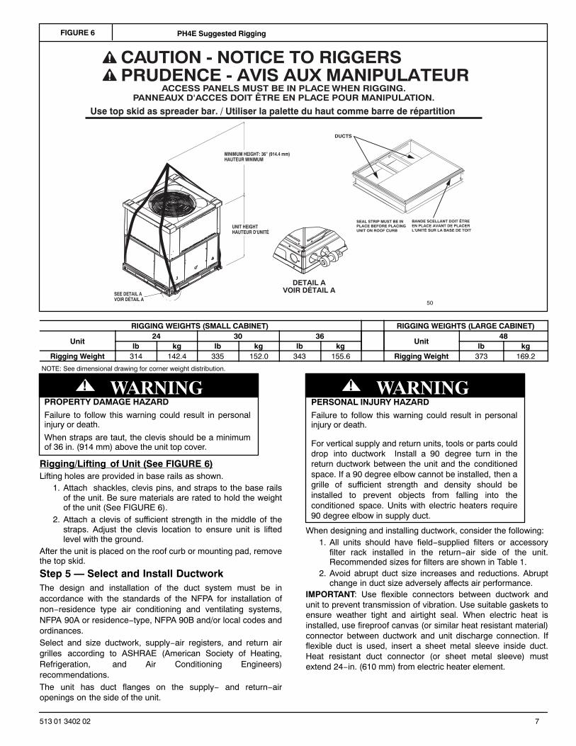
FIGURE 6 PH4E Suggested Rigging
ACCESS PANELS MUST BE IN PLACE WHEN RIGGING.PANNEAUX D'ACCES DOIT ÊTRE EN PLACE POUR MANIPULATION.
50CY502286 2.0
CAUTION - NOTICE TO RIGGERSPRUDENCE - AVIS AUX MANIPULATEUR
Use top skid as spreader bar. / Utiliser la palette du haut comme barre de répartition
SEAL STRIP MUST BE INPLACE BEFORE PLACINGUNIT ON ROOF CURB
DUCTS
DETAIL AVOIR DÉTAIL A
MINIMUM HEIGHT: 36" (914.4 mm)HAUTEUR MINIMUM
UNIT HEIGHTHAUTEUR D'UNITÉ
SEE DETAIL AVOIR DÉTAIL A
BANDE SCELLANT DOIT ÊTRE EN PLACE AVANT DE PLACER L'UNITÉ SUR LA BASE DE TOIT
RIGGING WEIGHTS (SMALL CABINET) RIGGING WEIGHTS (LARGE CABINET)
Unit24 30 36
Unit48
lb kg lb kg lb kg lb kgRigging Weight 314 142.4 335 152.0 343 155.6 Rigging Weight 373 169.2
NOTE: See dimensional drawing for corner weight distribution.
PROPERTY DAMAGE HAZARD
Failure to follow this warning could result in personalinjury or death.
When straps are taut, the clevis should be a minimumof 36 in. (914 mm) above the unit top cover.
! WARNING
Rigging/Lifting of Unit (See FIGURE 6)Lifting holes are provided in base rails as shown.
1. Attach shackles, clevis pins, and straps to the base railsof the unit. Be sure materials are rated to hold the weightof the unit (See FIGURE 6).
2. Attach a clevis of sufficient strength in the middle of thestraps. Adjust the clevis location to ensure unit is liftedlevel with the ground.
After the unit is placed on the roof curb or mounting pad, removethe top skid.
Step 5 — Select and Install DuctworkThe design and installation of the duct system must be inaccordance with the standards of the NFPA for installation ofnon−residence type air conditioning and ventilating systems,NFPA 90A or residence−type, NFPA 90B and/or local codes andordinances.Select and size ductwork, supply−air registers, and return airgrilles according to ASHRAE (American Society of Heating,Refrigeration, and Air Conditioning Engineers)recommendations.The unit has duct flanges on the supply− and return−airopenings on the side of the unit.
PERSONAL INJURY HAZARD
Failure to follow this warning could result in personalinjury or death.
For vertical supply and return units, tools or parts coulddrop into ductwork Install a 90 degree turn in thereturn ductwork between the unit and the conditionedspace. If a 90 degree elbow cannot be installed, then agrille of sufficient strength and density should beinstalled to prevent objects from falling into theconditioned space. Units with electric heaters require90 degree elbow in supply duct.
! WARNING
When designing and installing ductwork, consider the following:1. All units should have field−supplied filters or accessory
filter rack installed in the return−air side of the unit.Recommended sizes for filters are shown in Table 1.
2. Avoid abrupt duct size increases and reductions. Abruptchange in duct size adversely affects air performance.
IMPORTANT: Use flexible connectors between ductwork andunit to prevent transmission of vibration. Use suitable gaskets toensure weather tight and airtight seal. When electric heat isinstalled, use fireproof canvas (or similar heat resistant material)connector between ductwork and unit discharge connection. Ifflexible duct is used, insert a sheet metal sleeve inside duct.Heat resistant duct connector (or sheet metal sleeve) mustextend 24−in. (610 mm) from electric heater element.
8 513 01 3402 02
3. Size ductwork for cooling air quantity (cfm). The minimumair quantity for proper electric heater operation is listed inTable 2. Heater limit switches may trip at air quantitiesbelow those recommended.
4. Seal, insulate, and weatherproof all external ductwork.Seal, insulate and cover with a vapor barrier all ductworkpassing through conditioned spaces. Follow latest SheetMetal and Air Conditioning Contractors NationalAssociation (SMACNA) and Air Conditioning ContractorsAssociation (ACCA) minimum installation standards forresidential heating and air conditioning systems.
5. Secure all ducts to building structure. Flash, weatherproof,and vibration−isolate duct openings in wall or roofaccording to good construction practices.
CONFIGURING UNITS FOR DOWNFLOW (VERTICAL)DISCHARGE
ELECTRICAL SHOCK HAZARD
Failure to follow this warning could result in personalinjury or death.
Before performing service or maintenance operationson the system, turn off main power to unit and installlockout tag.
! WARNING
1. Open all electrical disconnects and install lockout tagbefore starting any service work.
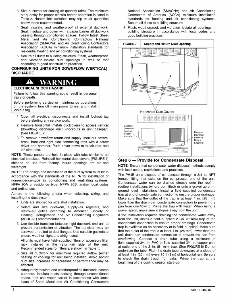
2. Remove horizontal (metal) ductcovers to access vertical(downflow) discharge duct knockouts in unit basepan.(See FIGURE 7.)
3. To remove downflow return and supply knockout covers,break front and right side connecting tabs with a screwdriver and hammer. Push cover down to break rear andleft side tabs.
NOTE: These panels are held in place with tabs similar to anelectrical knockout. Reinstall horizontal duct covers (FIGURE 7)shipped on unit from factory. Insure openings are air andwatertight.NOTE: The design and installation of the duct system must be inaccordance with the standards of the NFPA for installation ofnonresidence−type air conditioning and ventilating systems,NFPA 90A or residence−type, NFPA 90B; and/or local codesand ordinances.
Adhere to the following criteria when selecting, sizing, andinstalling the duct system:
1. Units are shipped for side shot installation.2. Select and size ductwork, supply−air registers, and
return−air grilles according to American Society ofHeating, Refrigeration and Air Conditioning Engineers(ASHRAE) recommendations.
3. Use flexible transition between rigid ductwork and unit toprevent transmission of vibration. The transition may bescrewed or bolted to duct flanges. Use suitable gaskets toensure weather−tight and airtight seal.
4. All units must have field−supplied filters or accessory filterrack installed in the return−air side of the unit.Recommended sizes for filters are shown in Table 1.
5. Size all ductwork for maximum required airflow (eitherheating or cooling) for unit being installed. Avoid abruptduct size increases or decreases or performance may beaffected.
6. Adequately insulate and weatherproof all ductwork locatedoutdoors. Insulate ducts passing through unconditionedspace, and use vapor barrier in accordance with latestissue of Sheet Metal and Air Conditioning Contractors
National Association (SMACNA) and Air ConditioningContractors of America (ACCA) minimum installationstandards for heating and air conditioning systems.Secure all ducts to building structure.
7. Flash, weatherproof, and vibration−isolate all openings inbuilding structure in accordance with local codes andgood building practices.
FIGURE 7 Supply and Return Duct Opening
Horizontal Duct Covers
BasepanDownflow(Vertical)SupplyKnockout
BasepanDownflow (Vertical)ReturnKnockout
Step 6 — Provide for Condensate DisposalNOTE: Ensure that condensate−water disposal methods complywith local codes, restrictions, and practices.
The PH4E units dispose of condensate through a 3/4 in. NPTfemale fitting that exits on the compressor end of the unit.Condensate water can be drained directly onto the roof inrooftop installations (where permitted) or onto a gravel apron inground level installations. Install a field−supplied condensatetrap at end of condensate connection to ensure proper drainage.Make sure that the outlet of the trap is at least 1 in. (25 mm)lower than the drain−pan condensate connection to prevent thepan from overflowing. Prime the trap with water. When using agravel apron, make sure it slopes away from the unit.If the installation requires draining the condensate water awayfrom the unit, install a field−supplied 2 −in. (51mm) trap at thecondensate connection to ensure proper drainage. Condensatetrap is available as an accessory or is field−supplied. Make surethat the outlet of the trap is at least 1 in. (25 mm) lower than theunit drain−pan condensate connection to prevent the pan fromoverflowing. Connect a drain tube using a minimum offield−supplied 3/4−in. PVC or field−supplied 3/4−in. copper pipeat outlet end of the 2−in. (51 mm) trap. (See FIGURE 8) Do notundersize the tube. Pitch the drain tube downward at a slope ofat least 1 in. (25 mm) every 10 ft (3 m) of horizontal run. Be sureto check the drain trough for leaks. Prime the trap at thebeginning of the cooling season start−up.
9513 01 3402 02
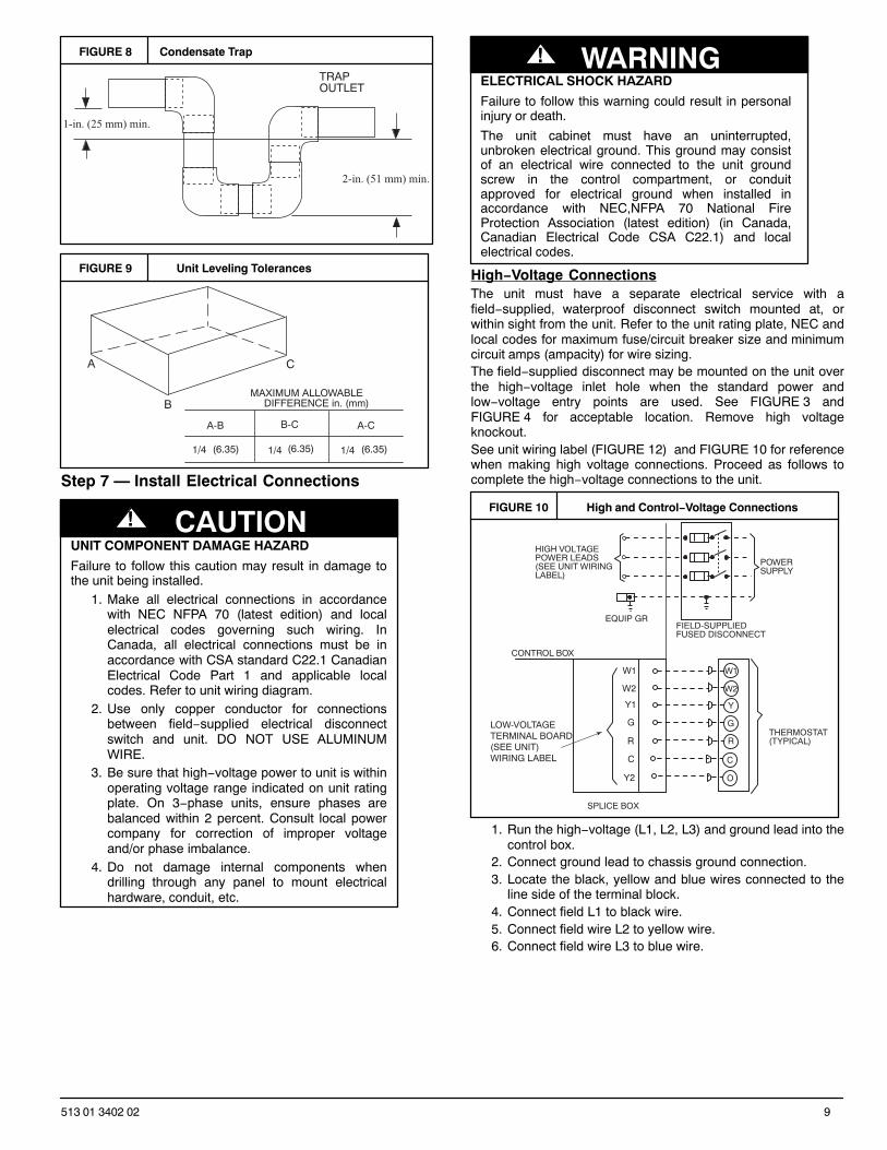
FIGURE 8 Condensate Trap
TRAPOUTLET
1-in. (25 mm) min.
2-in. (51 mm) min.
FIGURE 9 Unit Leveling Tolerances
A
B
C
MAXIMUM ALLOWABLEDIFFERENCE in. (mm)
A-C
1/4 1/4 1/4(6.35) (6.35) (6.35)
A-B B-C
Step 7 — Install Electrical Connections
UNIT COMPONENT DAMAGE HAZARD
Failure to follow this caution may result in damage tothe unit being installed.
1. Make all electrical connections in accordancewith NEC NFPA 70 (latest edition) and localelectrical codes governing such wiring. InCanada, all electrical connections must be inaccordance with CSA standard C22.1 CanadianElectrical Code Part 1 and applicable localcodes. Refer to unit wiring diagram.
2. Use only copper conductor for connectionsbetween field−supplied electrical disconnectswitch and unit. DO NOT USE ALUMINUMWIRE.
3. Be sure that high−voltage power to unit is withinoperating voltage range indicated on unit ratingplate. On 3−phase units, ensure phases arebalanced within 2 percent. Consult local powercompany for correction of improper voltageand/or phase imbalance.
4. Do not damage internal components whendrilling through any panel to mount electricalhardware, conduit, etc.
! CAUTION
ELECTRICAL SHOCK HAZARD
Failure to follow this warning could result in personalinjury or death.
The unit cabinet must have an uninterrupted,unbroken electrical ground. This ground may consistof an electrical wire connected to the unit groundscrew in the control compartment, or conduitapproved for electrical ground when installed inaccordance with NEC,NFPA 70 National FireProtection Association (latest edition) (in Canada,Canadian Electrical Code CSA C22.1) and localelectrical codes.
! WARNING
High−Voltage ConnectionsThe unit must have a separate electrical service with afield−supplied, waterproof disconnect switch mounted at, orwithin sight from the unit. Refer to the unit rating plate, NEC andlocal codes for maximum fuse/circuit breaker size and minimumcircuit amps (ampacity) for wire sizing.The field−supplied disconnect may be mounted on the unit overthe high−voltage inlet hole when the standard power andlow−voltage entry points are used. See FIGURE 3 andFIGURE 4 for acceptable location. Remove high voltageknockout.See unit wiring label (FIGURE 12) and FIGURE 10 for referencewhen making high voltage connections. Proceed as follows tocomplete the high−voltage connections to the unit.
FIGURE 10 High and Control−Voltage Connections
POWERSUPPLY
FIELD-SUPPLIEDFUSED DISCONNECT
HIGH VOLTAGEPOWER LEADS(SEE UNIT WIRINGLABEL)
EQUIP GR
CONTROL BOX
W1
Y
G
R
C
THERMOSTAT(TYPICAL)
W2
O
SPLICE BOX
LOW-VOLTAGETERMINAL BOARD(SEE UNIT)WIRING LABEL
W2
W1
Y1
G
R
C
Y2
1. Run the high−voltage (L1, L2, L3) and ground lead into thecontrol box.
2. Connect ground lead to chassis ground connection.3. Locate the black, yellow and blue wires connected to the
line side of the terminal block.4. Connect field L1 to black wire.5. Connect field wire L2 to yellow wire.6. Connect field wire L3 to blue wire.
10 513 01 3402 02
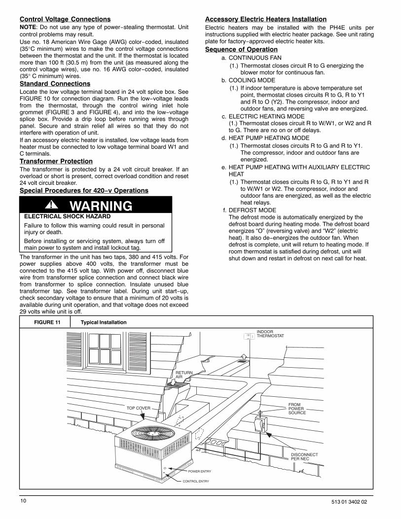
Control Voltage ConnectionsNOTE: Do not use any type of power−stealing thermostat. Unitcontrol problems may result.Use no. 18 American Wire Gage (AWG) color−coded, insulated(35°C minimum) wires to make the control voltage connectionsbetween the thermostat and the unit. If the thermostat is locatedmore than 100 ft (30.5 m) from the unit (as measured along thecontrol voltage wires), use no. 16 AWG color−coded, insulated(35° C minimum) wires.Standard ConnectionsLocate the low voltage terminal board in 24 volt splice box. SeeFIGURE 10 for connection diagram. Run the low−voltage leadsfrom the thermostat, through the control wiring inlet holegrommet (FIGURE 3 and FIGURE 4), and into the low−voltagesplice box. Provide a drip loop before running wires throughpanel. Secure and strain relief all wires so that they do notinterfere with operation of unit.If an accessory electric heater is installed, low voltage leads fromheater must be connected to low voltage terminal board W1 andC terminals.Transformer ProtectionThe transformer is protected by a 24 volt circuit breaker. If anoverload or short is present, correct overload condition and reset24 volt circuit breaker.Special Procedures for 420−v Operations
ELECTRICAL SHOCK HAZARD
Failure to follow this warning could result in personalinjury or death.
Before installing or servicing system, always turn offmain power to system and install lockout tag.
! WARNING
The transformer in the unit has two taps, 380 and 415 volts. Forpower supplies above 400 volts, the transformer must beconnected to the 415 volt tap. With power off, disconnect bluewire from transformer splice connection and connect black wirefrom transformer to splice connection. Insulate unused bluetransformer tap. See transformer label. During unit start−up,check secondary voltage to ensure that a minimum of 20 volts isavailable during unit operation, and that voltage does not exceed29 volts while unit is off.
Accessory Electric Heaters InstallationElectric heaters may be installed with the PH4E units perinstructions supplied with electric heater package. See unit ratingplate for factory−approved electric heater kits.Sequence of Operation
a. CONTINUOUS FAN(1.) Thermostat closes circuit R to G energizing the
blower motor for continuous fan.b. COOLING MODE
(1.) If indoor temperature is above temperature setpoint, thermostat closes circuits R to G, R to Y1and R to O (Y2). The compressor, indoor andoutdoor fans, and reversing valve are energized.
c. ELECTRIC HEATING MODE(1.) Thermostat closes circuit R to W/W1, or W2 and Rto G. There are no on or off delays.
d. HEAT PUMP HEATING MODE(1.) Thermostat closes circuits R to G and R to Y1.
The compressor, indoor and outdoor fans areenergized.
e. HEAT PUMP HEATING WITH AUXILIARY ELECTRICHEAT(1.) Thermostat closes circuits R to G, R to Y1 and R
to W/W1 or W2. The compressor, indoor andoutdoor fans are energized, as well as the electricheat relays.
f. DEFROST MODEThe defrost mode is automatically energized by thedefrost board during heating mode. The defrost boardenergizes “O” (reversing valve) and “W2” (electricheat). It also de−energizes the outdoor fan. Whendefrost is complete, unit will return to heating mode. Ifroom thermostat is satisfied during defrost, unit willshut down and restart in defrost on next call for heat.
FIGURE 11 Typical Installation
INDOORTHERMOSTAT
DISCONNECTPER NEC
FROMPOWERSOURCE
RETURNAIR
TOP COVER
POWER ENTRY
CONTROL ENTRY
11513 01 3402 02
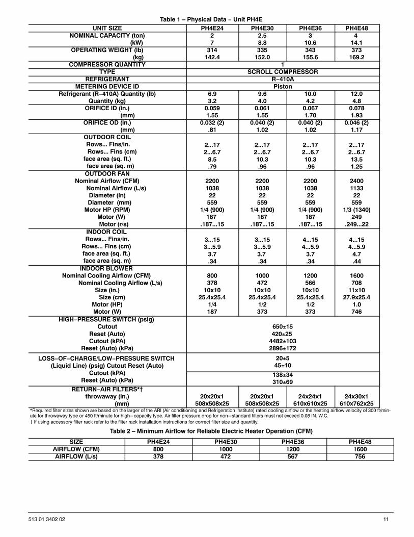
Table 1 – Physical Data − Unit PH4EUNIT SIZE PH4E24 PH4E30 PH4E36 PH4E48
NOMINAL CAPACITY (ton) (kW)
27
2.58.8
310.6
4 14.1
OPERATING WEIGHT (lb) (kg)
314142.4
335152.0
343155.6
373169.2
COMPRESSOR QUANTITY 1TYPE SCROLL COMPRESSOR
REFRIGERANT R−410AMETERING DEVICE ID Piston
Refrigerant (R−410A) Quantity (lb)Quantity (kg)
6.93.2
9.64.0
10.04.2
12.04.8
ORIFICE ID (in.) (mm)
0.0591.55
0.0611.55
0.0671.70
0.0781.93
ORIFICE OD (in.) (mm)
0.032 (2).81
0.040 (2)1.02
0.040 (2)1.02
0.046 (2)1.17
OUTDOOR COIL Rows... Fins/in.
Rows... Fins (cm) face area (sq. ft.)
face area (sq. m)
2...172...6.7
8.5.79
2...172...6.710.3.96
2...172...6.710.3.96
2...172...6.713.51.25
OUTDOOR FANNominal Airflow (CFM)
Nominal Airflow (L/s)Diameter (in)
Diameter (mm)Motor HP (RPM)
Motor (W) Motor (r/s)
22001038
22559
1/4 (900)187
.187...15
22001038
22559
1/4 (900)187
.187...15
22001038
22559
1/4 (900)187
.187...15
2400113322
5591/3 (1340)
249.249...22
INDOOR COIL Rows... Fins/in.
Rows... Fins (cm) face area (sq. ft.) face area (sq. m)
3...153...5.9
3.7.34
3...153...5.9
3.7 .34
4...154...5.9
3.7.34
4...154...5.9
4.7.44
INDOOR BLOWER Nominal Cooling Airflow (CFM)
Nominal Cooling Airflow (L/s)Size (in.)
Size (cm)Motor (HP)Motor (W)
800378
10x1025.4x25.4
1/4187
1000472
10x1025.4x25.4
1/2373
1200566
10x1025.4x25.4
1/2373
1600708
11x1027.9x25.4
1.0746
HIGH−PRESSURE SWITCH (psig) Cutout
Reset (Auto)Cutout (kPA)
Reset (Auto) (kPa)
650�15420�25
4482�1032896�172
LOSS−OF−CHARGE/LOW−PRESSURE SWITCH (Liquid Line) (psig) Cutout Reset (Auto)
Cutout (kPA)Reset (Auto) (kPa)
20�545�10
138�34310�69
RETURN−AIR FILTERS*�throwaway (in.) (mm)
20x20x1508x508x25
20x20x1508x508x25
24x24x1610x610x25
24x30x1610x762x25
*Required filter sizes shown are based on the larger of the ARI (Air conditioning and Refrigeration Institute) rated cooling airflow or the heating airflow velocity of 300 ft/minute for throwaway type or 450 ft/minute for high-capacity type. Air filter pressure drop for non-standard filters must not exceed 0.08 IN. W.C.
� If using accessory filter rack refer to the filter rack installation instructions for correct filter size and quantity.
Table 2 – Minimum Airflow for Reliable Electric Heater Operation (CFM)
SIZE PH4E24 PH4E30 PH4E36 PH4E48AIRFLOW (CFM) 800 1000 1200 1600AIRFLOW (L/s) 378 472 567 756
12 513 01 3402 02
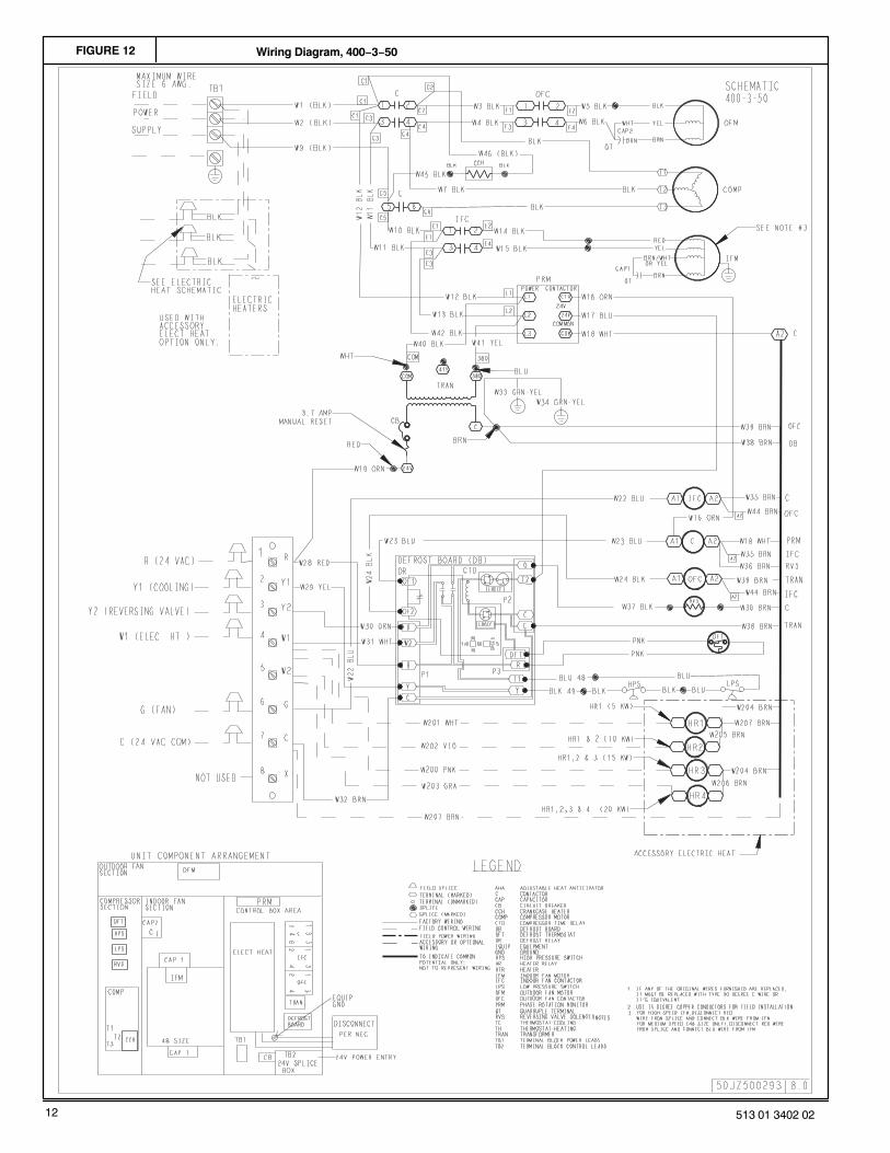
FIGURE 12 Wiring Diagram, 400−3−50
13513 01 3402 02
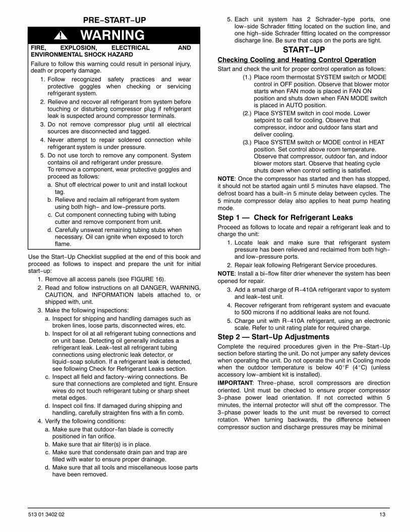
PRE−START−UP
FIRE, EXPLOSION, ELECTRICAL ANDENVIRONMENTAL SHOCK HAZARD
Failure to follow this warning could result in personal injury,death or property damage.
1. Follow recognized safety practices and wearprotective goggles when checking or servicingrefrigerant system.
2. Relieve and recover all refrigerant from system beforetouching or disturbing compressor plug if refrigerantleak is suspected around compressor terminals.
3. Do not remove compressor plug until all electricalsources are disconnected and tagged.
4. Never attempt to repair soldered connection whilerefrigerant system is under pressure.
5. Do not use torch to remove any component. Systemcontains oil and refrigerant under pressure.To remove a component, wear protective goggles andproceed as follows:a. Shut off electrical power to unit and install lockout
tag.b. Relieve and reclaim all refrigerant from system
using both high− and low−pressure ports.c. Cut component connecting tubing with tubing
cutter and remove component from unit.d. Carefully unsweat remaining tubing stubs when
necessary. Oil can ignite when exposed to torchflame.
! WARNING
Use the Start−Up Checklist supplied at the end of this book andproceed as follows to inspect and prepare the unit for initialstart−up:
1. Remove all access panels (see FIGURE 16).2. Read and follow instructions on all DANGER, WARNING,
CAUTION, and INFORMATION labels attached to, orshipped with, unit.
3. Make the following inspections:a. Inspect for shipping and handling damages such as
broken lines, loose parts, disconnected wires, etc.b. Inspect for oil at all refrigerant tubing connections and
on unit base. Detecting oil generally indicates arefrigerant leak. Leak−test all refrigerant tubingconnections using electronic leak detector, orliquid−soap solution. If a refrigerant leak is detected,see following Check for Refrigerant Leaks section.
c. Inspect all field and factory−wiring connections. Besure that connections are completed and tight. Ensurewires do not touch refrigerant tubing or sharp sheetmetal edges.
d. Inspect coil fins. If damaged during shipping andhandling, carefully straighten fins with a fin comb.
4. Verify the following conditions:a. Make sure that outdoor−fan blade is correctly
positioned in fan orifice.b. Make sure that air filter(s) is in place.c. Make sure that condensate drain pan and trap are
filled with water to ensure proper drainage.d. Make sure that all tools and miscellaneous loose parts
have been removed.
5. Each unit system has 2 Schrader−type ports, onelow−side Schrader fitting located on the suction line, andone high−side Schrader fitting located on the compressordischarge line. Be sure that caps on the ports are tight.
START−UPChecking Cooling and Heating Control OperationStart and check the unit for proper control operation as follows:
(1.) Place room thermostat SYSTEM switch or MODEcontrol in OFF position. Observe that blower motorstarts when FAN mode is placed in FAN ONposition and shuts down when FAN MODE switchis placed in AUTO position.
(2.) Place SYSTEM switch in cool mode. Lowersetpoint to call for cooling. Observe thatcompressor, indoor and outdoor fans start anddeliver cooling.
(3.) Place SYSTEM switch or MODE control in HEATposition. Set control above room temperature.Observe that compressor, outdoor fan, and indoorblower motors start. Observe that heating cycleshuts down when control setting is satisfied.
NOTE: Once the compressor has started and then has stopped,it should not be started again until 5 minutes have elapsed. Thedefrost board has a built−in 5 minute delay between cycles. The5 minute compressor delay also applies to heat pump heatingmode.
Step 1 — Check for Refrigerant LeaksProceed as follows to locate and repair a refrigerant leak and tocharge the unit:
1. Locate leak and make sure that refrigerant systempressure has been relieved and reclaimed from both high−and low−pressure ports.
2. Repair leak following Refrigerant Service procedures.NOTE: Install a bi−flow filter drier whenever the system has beenopened for repair.
3. Add a small charge of R−410A refrigerant vapor to systemand leak−test unit.
4. Recover refrigerant from refrigerant system and evacuateto 500 microns if no additional leaks are not found.
5. Charge unit with R−410A refrigerant, using an electronicscale. Refer to unit rating plate for required charge.
Step 2 — Start−Up AdjustmentsComplete the required procedures given in the Pre−Start−Upsection before starting the unit. Do not jumper any safety deviceswhen operating the unit. Do not operate the unit in Cooling modewhen the outdoor temperature is below 40�F (4�C) (unlessaccessory low−ambient kit is installed).IMPORTANT: Three−phase, scroll compressors are directionoriented. Unit must be checked to ensure proper compressor3−phase power lead orientation. If not corrected within 5minutes, the internal protector will shut off the compressor. The3−phase power leads to the unit must be reversed to correctrotation. When turning backwards, the difference betweencompressor suction and discharge pressures may be minimal
14 513 01 3402 02
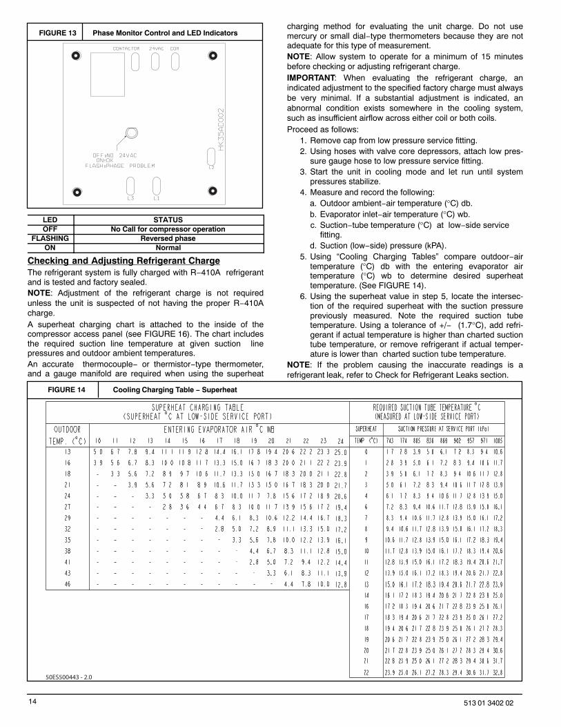
FIGURE 13 Phase Monitor Control and LED Indicators
LED STATUSOFF No Call for compressor operation
FLASHING Reversed phaseON Normal
Checking and Adjusting Refrigerant ChargeThe refrigerant system is fully charged with R−410A refrigerantand is tested and factory sealed.NOTE: Adjustment of the refrigerant charge is not requiredunless the unit is suspected of not having the proper R−410Acharge.A superheat charging chart is attached to the inside of thecompressor access panel (see FIGURE 16). The chart includesthe required suction line temperature at given suction linepressures and outdoor ambient temperatures.An accurate thermocouple− or thermistor−type thermometer,and a gauge manifold are required when using the superheat
charging method for evaluating the unit charge. Do not usemercury or small dial−type thermometers because they are notadequate for this type of measurement.NOTE: Allow system to operate for a minimum of 15 minutesbefore checking or adjusting refrigerant charge.IMPORTANT: When evaluating the refrigerant charge, anindicated adjustment to the specified factory charge must alwaysbe very minimal. If a substantial adjustment is indicated, anabnormal condition exists somewhere in the cooling system,such as insufficient airflow across either coil or both coils.Proceed as follows:
1. Remove cap from low pressure service fitting.2. Using hoses with valve core depressors, attach low pres-
sure gauge hose to low pressure service fitting.3. Start the unit in cooling mode and let run until system
pressures stabilize.4. Measure and record the following:
a. Outdoor ambient−air temperature (°C) db.b. Evaporator inlet−air temperature (°C) wb.c. Suction−tube temperature (°C) at low−side service
fitting.d. Suction (low−side) pressure (kPA).
5. Using “Cooling Charging Tables” compare outdoor−airtemperature (°C) db with the entering evaporator airtemperature (°C) wb to determine desired superheattemperature. (See FIGURE 14).
6. Using the superheat value in step 5, locate the intersec-tion of the required superheat with the suction pressurepreviously measured. Note the required suction tubetemperature. Using a tolerance of +/− (1.7°C), add refri-gerant if actual temperature is higher than charted suctiontube temperature, or remove refrigerant if actual temper-ature is lower than charted suction tube temperature.
NOTE: If the problem causing the inaccurate readings is arefrigerant leak, refer to Check for Refrigerant Leaks section.
FIGURE 14 Cooling Charging Table − Superheat
50ES500443 - 2.0
15513 01 3402 02
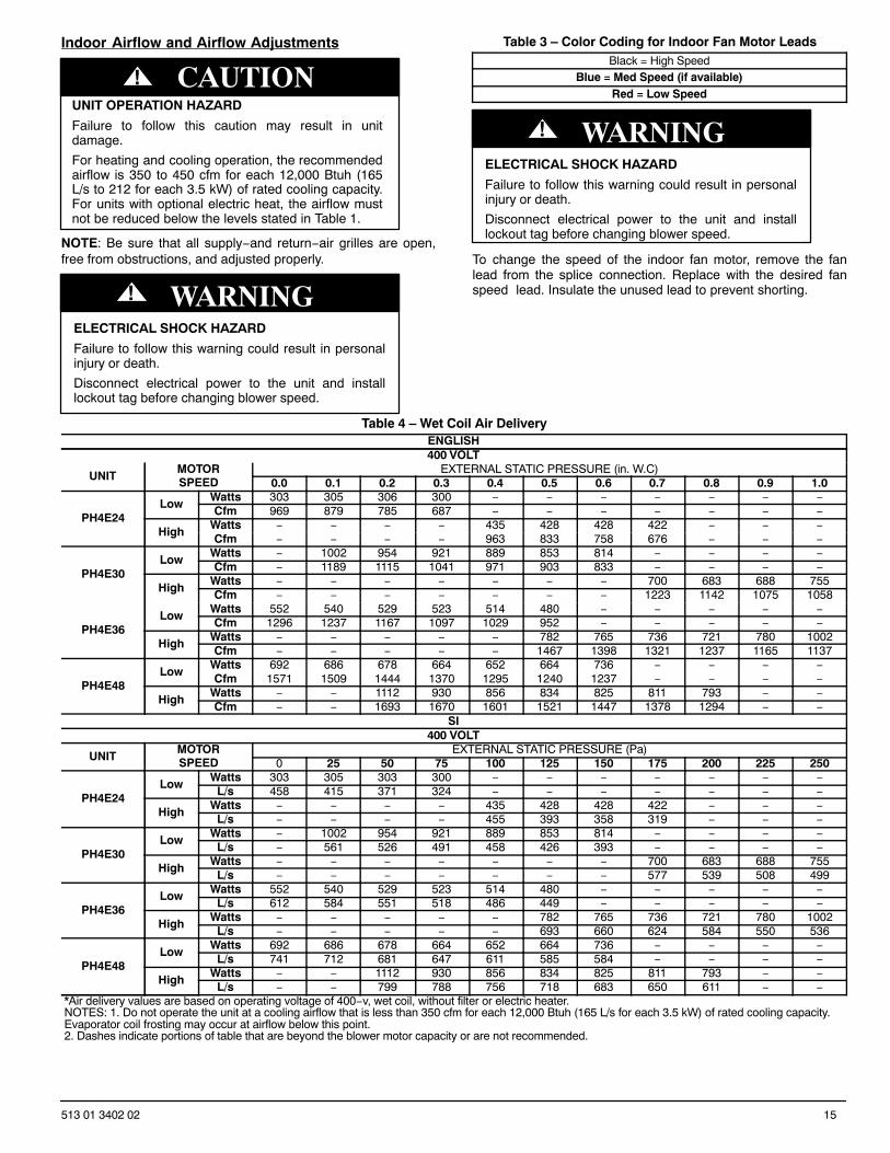
Indoor Airflow and Airflow Adjustments
UNIT OPERATION HAZARD
Failure to follow this caution may result in unitdamage.
For heating and cooling operation, the recommendedairflow is 350 to 450 cfm for each 12,000 Btuh (165L/s to 212 for each 3.5 kW) of rated cooling capacity.For units with optional electric heat, the airflow mustnot be reduced below the levels stated in Table 1.
CAUTION!
NOTE: Be sure that all supply−and return−air grilles are open,free from obstructions, and adjusted properly.
ELECTRICAL SHOCK HAZARD
Failure to follow this warning could result in personalinjury or death.
Disconnect electrical power to the unit and installlockout tag before changing blower speed.
! WARNING
Table 3 – Color Coding for Indoor Fan Motor LeadsBlack = High Speed
Blue = Med Speed (if available)Red = Low Speed
ELECTRICAL SHOCK HAZARD
Failure to follow this warning could result in personalinjury or death.
Disconnect electrical power to the unit and installlockout tag before changing blower speed.
! WARNING
To change the speed of the indoor fan motor, remove the fanlead from the splice connection. Replace with the desired fanspeed lead. Insulate the unused lead to prevent shorting.
Table 4 – Wet Coil Air DeliveryENGLISH400 VOLT
UNITMOTORSPEED
EXTERNAL STATIC PRESSURE (in. W.C)0.0 0.1 0.2 0.3 0.4 0.5 0.6 0.7 0.8 0.9 1.0
PH4E24Low
Watts 303 305 306 300 − − − − − − −Cfm 969 879 785 687 − − − − − − −
HighWatts − − − − 435 428 428 422 − − −Cfm − − − − 963 833 758 676 − − −
PH4E30Low
Watts − 1002 954 921 889 853 814 − − − −Cfm − 1189 1115 1041 971 903 833 − − − −
HighWatts − − − − − − − 700 683 688 755Cfm − − − − − − − 1223 1142 1075 1058
PH4E36Low
Watts 552 540 529 523 514 480 − − − − −Cfm 1296 1237 1167 1097 1029 952 − − − − −
HighWatts − − − − − 782 765 736 721 780 1002Cfm − − − − − 1467 1398 1321 1237 1165 1137
PH4E48Low
Watts 692 686 678 664 652 664 736 − − − −Cfm 1571 1509 1444 1370 1295 1240 1237 − − − −
HighWatts − − 1112 930 856 834 825 811 793 − −Cfm − − 1693 1670 1601 1521 1447 1378 1294 − −
SI400 VOLT
UNITMOTORSPEED
EXTERNAL STATIC PRESSURE (Pa)0 25 50 75 100 125 150 175 200 225 250
PH4E24Low
Watts 303 305 303 300 − − − − − − −L/s 458 415 371 324 − − − − − − −
HighWatts − − − − 435 428 428 422 − − −
L/s − − − − 455 393 358 319 − − −
PH4E30Low
Watts − 1002 954 921 889 853 814 − − − −L/s − 561 526 491 458 426 393 − − − −
HighWatts − − − − − − − 700 683 688 755
L/s − − − − − − − 577 539 508 499
PH4E36Low
Watts 552 540 529 523 514 480 − − − − −L/s 612 584 551 518 486 449 − − − − −
HighWatts − − − − − 782 765 736 721 780 1002
L/s − − − − − 693 660 624 584 550 536
PH4E48Low
Watts 692 686 678 664 652 664 736 − − − −L/s 741 712 681 647 611 585 584 − − − −
HighWatts − − 1112 930 856 834 825 811 793 − −
L/s − − 799 788 756 718 683 650 611 − −*Air delivery values are based on operating voltage of 400−v, wet coil, without filter or electric heater. NOTES: 1. Do not operate the unit at a cooling airflow that is less than 350 cfm for each 12,000 Btuh (165 L/s for each 3.5 kW) of rated cooling capacity. Evaporator coil frosting may occur at airflow below this point.2. Dashes indicate portions of table that are beyond the blower motor capacity or are not recommended.
16 513 01 3402 02
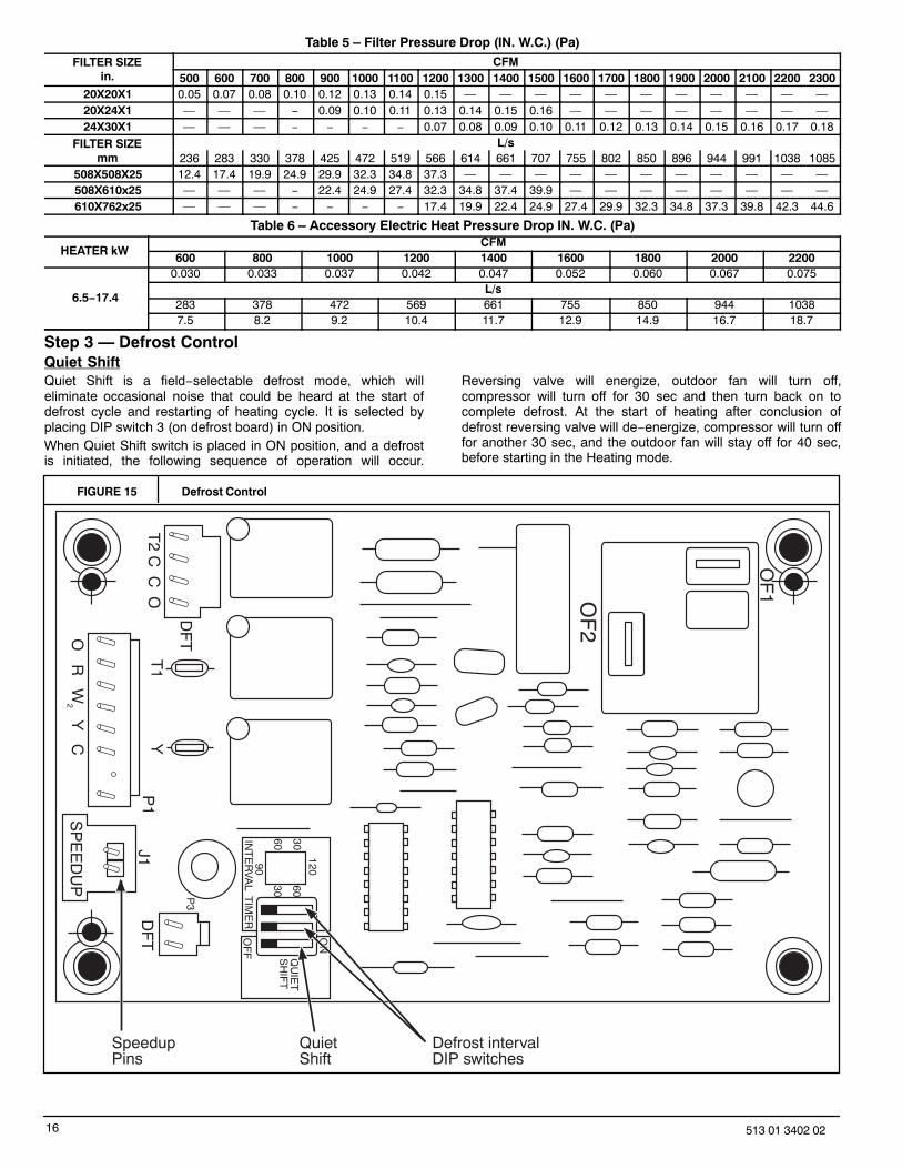
Table 5 – Filter Pressure Drop (IN. W.C.) (Pa)FILTER SIZE
in.CFM
500 600 700 800 900 1000 1100 1200 1300 1400 1500 1600 1700 1800 1900 2000 2100 2200 230020X20X1 0.05 0.07 0.08 0.10 0.12 0.13 0.14 0.15 — — — — — — — — — — —20X24X1 — — — − 0.09 0.10 0.11 0.13 0.14 0.15 0.16 — — — — — — — —24X30X1 — — — − − − − 0.07 0.08 0.09 0.10 0.11 0.12 0.13 0.14 0.15 0.16 0.17 0.18
FILTER SIZEmm
L/s236 283 330 378 425 472 519 566 614 661 707 755 802 850 896 944 991 1038 1085
508X508X25 12.4 17.4 19.9 24.9 29.9 32.3 34.8 37.3 — — — — — — — — — — —508X610x25 — — — − 22.4 24.9 27.4 32.3 34.8 37.4 39.9 — — — — — — — —610X762x25 — — — − − − − 17.4 19.9 22.4 24.9 27.4 29.9 32.3 34.8 37.3 39.8 42.3 44.6
Table 6 – Accessory Electric Heat Pressure Drop IN. W.C. (Pa)
HEATER kWCFM
600 800 1000 1200 1400 1600 1800 2000 2200
6.5−17.4
0.030 0.033 0.037 0.042 0.047 0.052 0.060 0.067 0.075L/s
283 378 472 569 661 755 850 944 10387.5 8.2 9.2 10.4 11.7 12.9 14.9 16.7 18.7
Step 3 — Defrost ControlQuiet ShiftQuiet Shift is a field−selectable defrost mode, which willeliminate occasional noise that could be heard at the start ofdefrost cycle and restarting of heating cycle. It is selected byplacing DIP switch 3 (on defrost board) in ON position.When Quiet Shift switch is placed in ON position, and a defrostis initiated, the following sequence of operation will occur.
Reversing valve will energize, outdoor fan will turn off,compressor will turn off for 30 sec and then turn back on tocomplete defrost. At the start of heating after conclusion ofdefrost reversing valve will de−energize, compressor will turn offfor another 30 sec, and the outdoor fan will stay off for 40 sec,before starting in the Heating mode.
FIGURE 15 Defrost Control
OF
2
OF
1
ON
QU
IET
SH
IFT
120
3060
6030
90IN
TE
RV
AL T
IME
RO
FF
P3
DF
T
O R
W2 Y
C
T2 C
C O
DF
T
T1
YP
1J1
SP
EE
DU
P
SpeedupPins
Defrost intervalDIP switches
QuietShift
17513 01 3402 02
DefrostThe defrost control is a time/temperature control which includesa field−selectable time period (DIP switch 1 and 2 on the board)between defrost cycles of 30, 60, 90, or 120 minutes (factory setat 60 minutes). To initiate a forced defrost, two options areavailable depending on the status of the defrost thermostat.If defrost thermostat is closed, speed−up pins (J1) must beshorted by placing a flat head screw driver in between for 5 secand releasing, to observe a complete defrost cycle. When theQuiet Shift switch is selected, compressor will be turned off fortwo 30 sec intervals during this complete defrost cycle, asexplained previously. When Quiet Shift switch is in factory defaultOFF position, a normal and complete defrost cycle will beobserved.If defrost thermostat is in open position, and speedup pins areshorted (with a flat head screw driver) for 5 sec and released, ashort defrost cycle will be observed (actual length is dependentupon the selected Quiet Shift position). When Quiet Shift switchis in ON position, the length of defrost is 1 minute (30 seccompressor off period followed by 30 sec of defrost withcompressor operation). On return to heating operation,compressor will again turn off for an additional 30 sec and theoutdoor fan for 40 sec. When the Quiet Shift is in OFF position,only a brief 30 sec. cycle will be observed.NOTE: Unit will remain in defrost until defrost thermostat reopensat approximately 65�F +/−5�F (18�C +/− 2.8�C) coil temperatureat liquid line or remainder of defrost cycle time.
MAINTENANCETo ensure continuing high performance, and to minimize thepossibility of premature equipment failure, periodic maintenancemust be performed on this equipment. This heat pump unitshould be inspected at least once each year by a qualifiedservice person. To troubleshoot unit, refer to Table 7.NOTE: TO EQUIPMENT OWNER: Consult your local dealerabout the availability of a maintenance contract.
PERSONAL INJURY AND UNIT DAMAGE HAZARD
Failure to follow this warning could result in personalinjury or death and unit component damage.
The ability to properly perform maintenance on thisequipment requires certain expertise, mechanicalskills, tools and equipment. If you do not possessthese, do not attempt to perform any maintenance onthis equipment, other than those proceduresrecommended in the Owner’s Manual.
! WARNING
ELECTRICAL SHOCK HAZARD
Failure to follow these warnings could result inpersonal injury or death:
1. Turn off electrical power to the unit and install alockout tag before performing any maintenanceor service on this unit.
2. Use extreme caution when removing panelsand parts.
3. Never place anything combustible either onor in contact with the unit.
! WARNING
UNIT OPERATION HAZARD
Failure to follow this caution may result in improperoperation.
Errors made when reconnecting wires may causeimproper and dangerous operation. Label all wiresprior to disconnecting when servicing.
CAUTION!
The minimum maintenance requirements for this equipment areas follows:
1. Inspect air filter(s) each month. Clean or replace whennecessary.
2. Inspect indoor coil, drain pan, and condensate drain eachcooling season for cleanliness. Clean when necessary.
3. Inspect blower motor and wheel for cleanliness eachcooling season. Clean when necessary.
4. Check electrical connections for tightness and controls forproper operation each cooling season. Service whennecessary.
Step 1 — Air FilterIMPORTANT: Never operate the unit without a suitable air filter inthe return−air duct system. Always replace the filter with thesame dimensional size and type as originally installed. SeeTable 1 for recommended filter sizes.
Inspect air filter(s) at least once each month and replace(throwaway−type) or clean (cleanable−type) at least twice duringeach cooling season and twice during the heating season, orwhenever the filter becomes clogged with dust and lint.
Indoor Blower and MotorNOTE: All motors are pre−lubricated. Do not attempt to lubricatethese motors.
For longer life, operating economy, and continuing efficiency,clean accumulated dirt and grease from the blower wheel andmotor annually.
ELECTRICAL SHOCK HAZARD
Failure to follow this warning could result in personalinjury or death.
Disconnect and tag electrical power to the unit beforecleaning the blower motor and wheel.
! WARNING
To clean the blower motor and wheel:1. Remove and disassemble blower assembly as follows:
a. Remove blower access panel (see FIGURE 16).b. Disconnect indoor blower motor. Remove capacitor if
required.c. On all units remove blower assembly from unit.
Remove screws securing blower to blower partitionand slide assembly out. Be careful not to tearinsulation in blower compartment.
d. Ensure proper reassembly by marking blower wheeland motor in relation to blower housing beforedisassembly.
e. Loosen setscrew(s) that secures wheel to motor shaft,remove screws that secure motor mount brackets tohousing, and slide motor and motor mount out ofhousing.
2. Remove and clean blower wheel as follows:a. Ensure proper reassembly by marking wheel
orientation.
18 513 01 3402 02
b. Lift wheel from housing. When handling and/orcleaning blower wheel, be sure not to disturb balanceweights (clips) on blower wheel vanes.
c. Remove caked−on dirt from wheel and housing with abrush. Remove lint and/or dirt accumulations fromwheel and housing with vacuum cleaner, using softbrush attachment. Remove grease and oil with mildsolvent.
d. Reassemble wheel into housing.e. Reassemble motor into housing. Be sure setscrews
are tightened on motor shaft flats and not on roundpart of shaft. Reinstall blower into unit. Reinstall capa-citor.
f. Reconnect blower motor wiring.g. Reinstall blower access panel (see FIGURE 16).
3. Restore electrical power to unit. Start unit and check forproper blower rotation and motor speeds during coolingcycles.
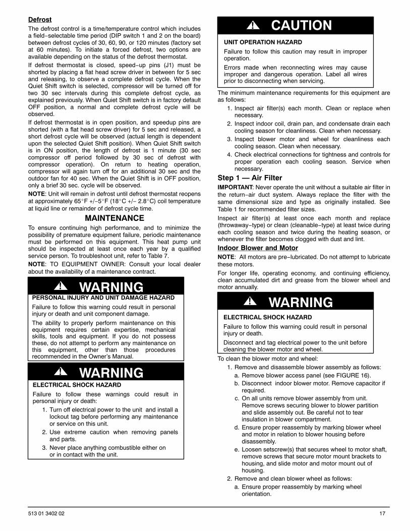
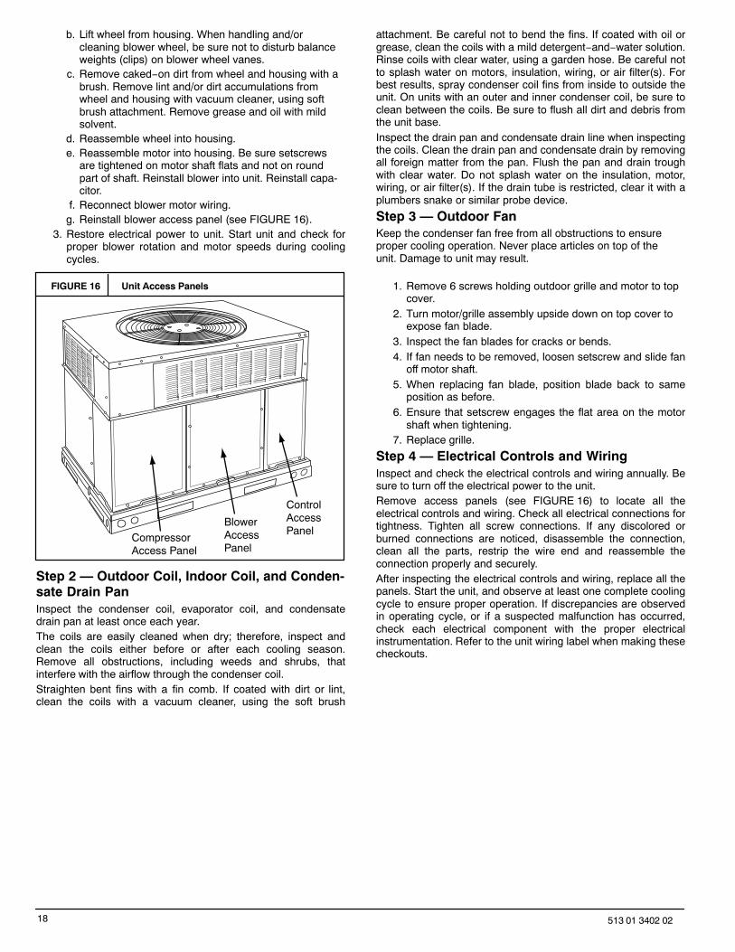
FIGURE 16 Unit Access Panels
CompressorAccess Panel
BlowerAccessPanel
ControlAccessPanel
Step 2 — Outdoor Coil, Indoor Coil, and Conden-sate Drain PanInspect the condenser coil, evaporator coil, and condensatedrain pan at least once each year.The coils are easily cleaned when dry; therefore, inspect andclean the coils either before or after each cooling season.Remove all obstructions, including weeds and shrubs, thatinterfere with the airflow through the condenser coil.Straighten bent fins with a fin comb. If coated with dirt or lint,clean the coils with a vacuum cleaner, using the soft brush
attachment. Be careful not to bend the fins. If coated with oil orgrease, clean the coils with a mild detergent−and−water solution.Rinse coils with clear water, using a garden hose. Be careful notto splash water on motors, insulation, wiring, or air filter(s). Forbest results, spray condenser coil fins from inside to outside theunit. On units with an outer and inner condenser coil, be sure toclean between the coils. Be sure to flush all dirt and debris fromthe unit base.Inspect the drain pan and condensate drain line when inspectingthe coils. Clean the drain pan and condensate drain by removingall foreign matter from the pan. Flush the pan and drain troughwith clear water. Do not splash water on the insulation, motor,wiring, or air filter(s). If the drain tube is restricted, clear it with aplumbers snake or similar probe device.
Step 3 — Outdoor FanKeep the condenser fan free from all obstructions to ensureproper cooling operation. Never place articles on top of theunit. Damage to unit may result.
1. Remove 6 screws holding outdoor grille and motor to topcover.
2. Turn motor/grille assembly upside down on top cover toexpose fan blade.
3. Inspect the fan blades for cracks or bends.4. If fan needs to be removed, loosen setscrew and slide fan
off motor shaft.5. When replacing fan blade, position blade back to same
position as before.6. Ensure that setscrew engages the flat area on the motor
shaft when tightening.7. Replace grille.
Step 4 — Electrical Controls and WiringInspect and check the electrical controls and wiring annually. Besure to turn off the electrical power to the unit.Remove access panels (see FIGURE 16) to locate all theelectrical controls and wiring. Check all electrical connections fortightness. Tighten all screw connections. If any discolored orburned connections are noticed, disassemble the connection,clean all the parts, restrip the wire end and reassemble theconnection properly and securely.After inspecting the electrical controls and wiring, replace all thepanels. Start the unit, and observe at least one complete coolingcycle to ensure proper operation. If discrepancies are observedin operating cycle, or if a suspected malfunction has occurred,check each electrical component with the proper electricalinstrumentation. Refer to the unit wiring label when making thesecheckouts.
19513 01 3402 02
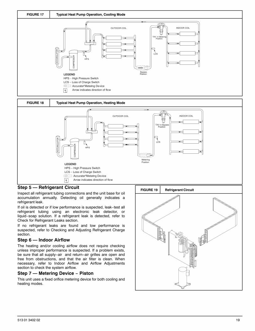
FIGURE 17 Typical Heat Pump Operation, Cooling Mode
CO
MP
RE
SS
OR
AC
CU
MU
LATO
R
OUTDOOR COIL INDOOR COIL
LCS
LEGENDHPS – High Pressure SwitchLCS – Loss of Charge Switch
Accurater ® Metering De viceArrow indicates direction of flo w
TXV in Metering Position
BypassPosition
HP S
FIGURE 18 Typical Heat Pump Operation, Heating Mode
CO
MP
RE
SS
OR
AC
CU
MU
LATO
R
OUTDOOR COIL INDOOR COIL
LCS
LEGENDHPS – High Pressure SwitchLCS – Loss of Charge Switch
Accurater ® Metering De viceArrow indicates direction of flo w
Position
HP S
TXV in Bypass
Metering Position
Step 5 — Refrigerant CircuitInspect all refrigerant tubing connections and the unit base for oilaccumulation annually. Detecting oil generally indicates arefrigerant leak.If oil is detected or if low performance is suspected, leak−test allrefrigerant tubing using an electronic leak detector, orliquid−soap solution. If a refrigerant leak is detected, refer toCheck for Refrigerant Leaks section.If no refrigerant leaks are found and low performance issuspected, refer to Checking and Adjusting Refrigerant Chargesection.
Step 6 — Indoor AirflowThe heating and/or cooling airflow does not require checkingunless improper performance is suspected. If a problem exists,be sure that all supply−air and return−air grilles are open andfree from obstructions, and that the air filter is clean. Whennecessary, refer to Indoor Airflow and Airflow Adjustmentssection to check the system airflow.
Step 7 — Metering Device − PistonThis unit uses a fixed orifice metering device for both cooling andheating modes.
FIGURE 19 Refrigerant Circuit
20 513 01 3402 02
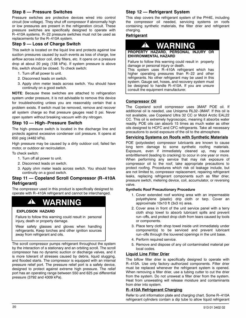
Step 8 — Pressure SwitchesPressure switches are protective devices wired into controlcircuit (low voltage). They shut off compressor if abnormally highor low pressures are present in the refrigeration circuit. Thesepressure switches are specifically designed to operate withR−410A systems. R−22 pressure switches must not be used asreplacements for the R−410A system.
Step 9 — Loss of Charge SwitchThis switch is located on the liquid line and protects against lowsuction pressures caused by such events as loss of charge, lowairflow across indoor coil, dirty filters, etc. It opens on a pressuredrop at about 20 psig (138 kPa). If system pressure is abovethis, switch should be closed. To check switch:
1. Turn off all power to unit.2. Disconnect leads on switch.3. Apply ohm meter leads across switch. You should have
continuity on a good switch.
NOTE: Because these switches are attached to refrigerationsystem under pressure, it is not advisable to remove this devicefor troubleshooting unless you are reasonably certain that aproblem exists. If switch must be removed, remove and recoverall system charge so that pressure gauges read 0 psi. Neveropen system without breaking vacuum with dry nitrogen.
Step 10 — High−Pressure SwitchThe high−pressure switch is located in the discharge line andprotects against excessive condenser coil pressure. It opens at650 psig (4482 kPa).
High pressure may be caused by a dirty outdoor coil, failed fanmotor, or outdoor air recirculation.To check switch:
1. Turn off all power to unit.2. Disconnect leads on switch.3. Apply ohm meter leads across switch. You should have
continuity on a good switch.
Step 11 — Copeland Scroll Compressor (R−410ARefrigerant)The compressor used in this product is specifically designed tooperate with R−410A refrigerant and cannot be interchanged.
EXPLOSION HAZARD
Failure to follow this warning could result in personalinjury, death or property damage.
Wear safety glasses and gloves when handlingrefrigerants. Keep torches and other ignition sourcesaway from refrigerant and oils.
! WARNING
The scroll compressor pumps refrigerant throughout the systemby the interaction of a stationary and an orbiting scroll. The scrollcompressor has no dynamic suction or discharge valves, and itis more tolerant of stresses caused by debris, liquid slugging,and flooded starts. The compressor is equipped with an internalpressure relief port. The pressure relief port is a safety device,designed to protect against extreme high pressure. The reliefport has an operating range between 550 and 625 psi differentialpressure (3792 and 4309 kPa).
Step 12 — Refrigerant SystemThis step covers the refrigerant system of the PH4E, includingthe compressor oil needed, servicing systems on roofscontaining synthetic materials, the filter drier and refrigerantcharging.
Refrigerant
PROPERTY HAZARD, PERSONAL INJURY ORENVIRONMENTAL HAZARD
Failure to follow this warning could result in propertydamage or personal injury or death.This system uses R−410A refrigerant which hashigher operating pressures than R−22 and otherrefrigerants. No other refrigerant may be used in thissystem. Gauge set, hoses, and recovery system mustbe designed to handle R−410A. If you are unsureconsult the equipment manufacturer.
! WARNING
Compressor OilThe Copeland scroll compressor uses 3MAF POE oil. Ifadditional oil is needed, use Uniqema RL32−3MAF. If this oil isnot available, use Copeland Ultra 32 CC or Mobil Arctic EAL22CC. This oil is extremely hygroscopic, meaning it absorbs waterreadily. POE oils can absorb 15 times as much water as otheroils designed to HCFC and CFC refrigerants. Take all necessaryprecautions to avoid exposure of the oil to the atmosphere.
Servicing Systems on Roofs with Synthetic MaterialsPOE (polyolester) compressor lubricants are known to causelong term damage to some synthetic roofing materials.Exposure, even if immediately cleaned up, may causeembrittlement (leading to cracking) to occur in one year or more.When performing any service that may risk exposure ofcompressor oil to the roof, take appropriate precautions toprotect roofing. Procedures which risk oil leakage include, butare not limited to, compressor replacement, repairing refrigerantleaks, replacing refrigerant components such as filter drier,pressure switch, metering device, coil, accumulator, or reversingvalve.Synthetic Roof Precautionary Procedure
1. Cover extended roof working area with an impermeablepolyethylene (plastic) drip cloth or tarp. Cover anapproximate 10x10 ft (3x3 m) area.
2. Cover area in front of the unit service panel with a terrycloth shop towel to absorb lubricant spills and preventrun−offs, and protect drop cloth from tears caused by toolsor components.
3. Place terry cloth shop towel inside unit immediately undercomponent(s) to be serviced and prevent lubricantrun−offs through the louvered openings in the unit base.
4. Perform required service.5. Remove and dispose of any oil contaminated material per
local codes.
Liquid Line Filter DrierThe biflow filter drier is specifically designed to operate withR−410A. Use only factory−authorized components. Filter driermust be replaced whenever the refrigerant system is opened.When removing a filter drier, use a tubing cutter to cut the drierfrom the system. Do not unsweat a filter drier from the system.Heat from unsweating will release moisture and contaminantsfrom drier into system.
R−410A Refrigerant ChargingRefer to unit information plate and charging chart. Some R−410Arefrigerant cylinders contain a dip tube to allow liquid refrigerant
21513 01 3402 02
to flow from cylinder in upright position. For cylinders equippedwith a dip tube, charge R−410A units with cylinder in uprightposition and a commercial metering device in manifold hose.Charge refrigerant into suction−line.
Step 13 — System InformationLoss of Charge SwitchThe loss of charge switch is a protective device wired into controlcircuit (low voltage). It shuts off the compressor if abnormally lowpressures are present in the refrigeration circuit.NOTE: Because these switches are attached to refrigerationsystem under pressure, it is not advisable to remove this devicefor troubleshooting unless you are reasonably certain that aproblem exists. If switch must be removed, remove and recoverall system charge so that pressure gauges read zero gauge.Never open system without breaking vacuum with dry nitrogen.
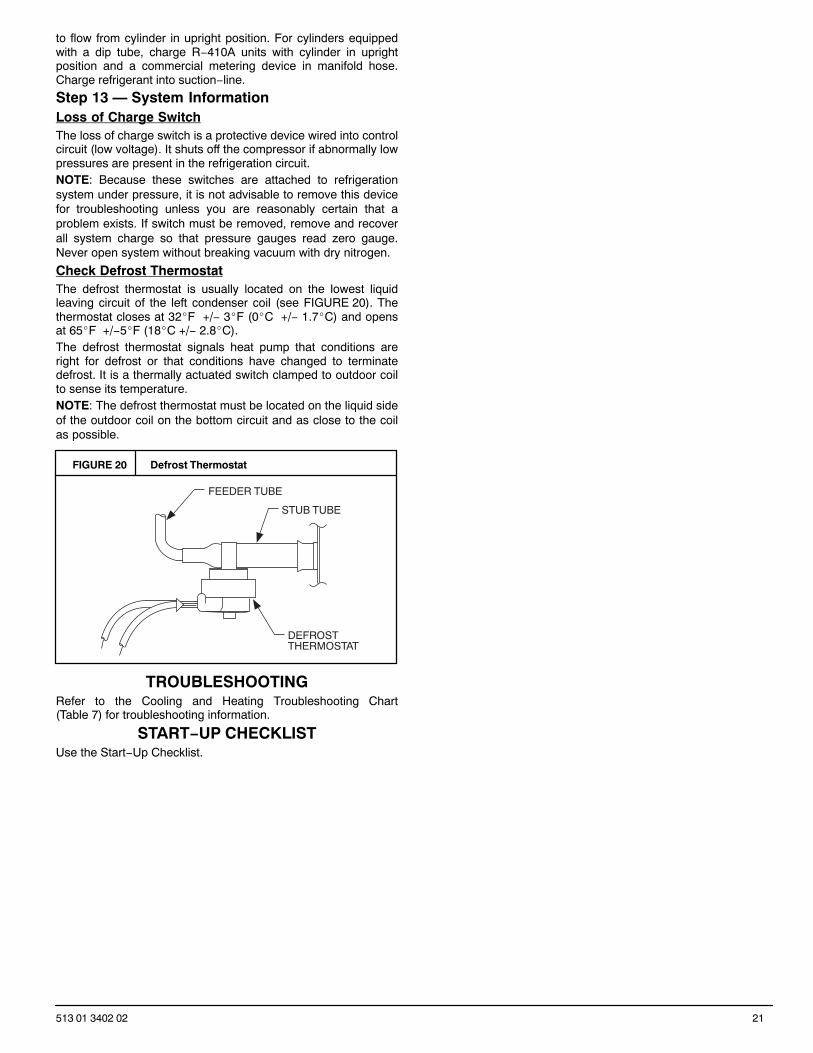
Check Defrost ThermostatThe defrost thermostat is usually located on the lowest liquidleaving circuit of the left condenser coil (see FIGURE 20). Thethermostat closes at 32�F +/− 3�F (0�C +/− 1.7�C) and opensat 65�F +/−5�F (18�C +/− 2.8�C).The defrost thermostat signals heat pump that conditions areright for defrost or that conditions have changed to terminatedefrost. It is a thermally actuated switch clamped to outdoor coilto sense its temperature.NOTE: The defrost thermostat must be located on the liquid sideof the outdoor coil on the bottom circuit and as close to the coilas possible.
FIGURE 20 Defrost Thermostat
FEEDER TUBE
STUB TUBE
DEFROSTTHERMOSTAT
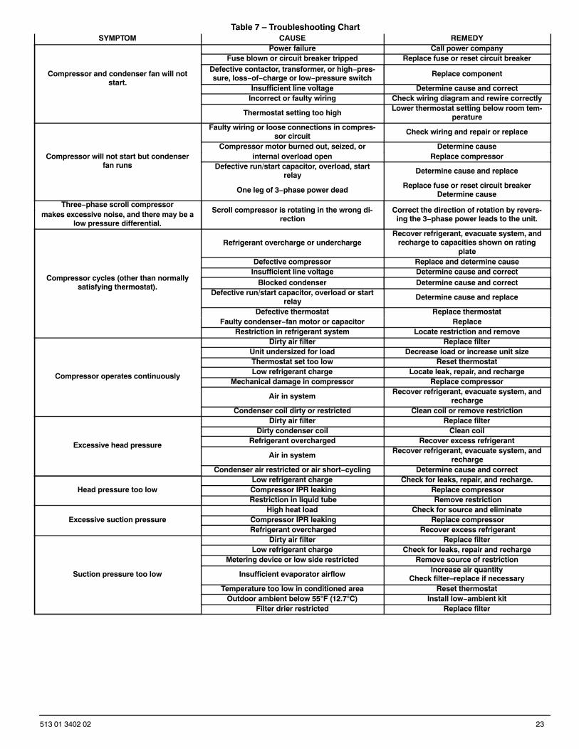
TROUBLESHOOTINGRefer to the Cooling and Heating Troubleshooting Chart(Table 7) for troubleshooting information.
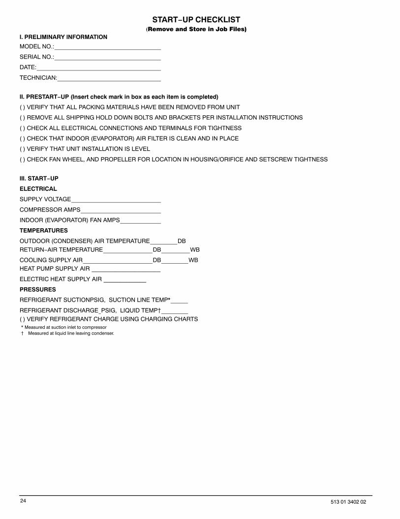
START−UP CHECKLISTUse the Start−Up Checklist.
22 513 01 3402 02
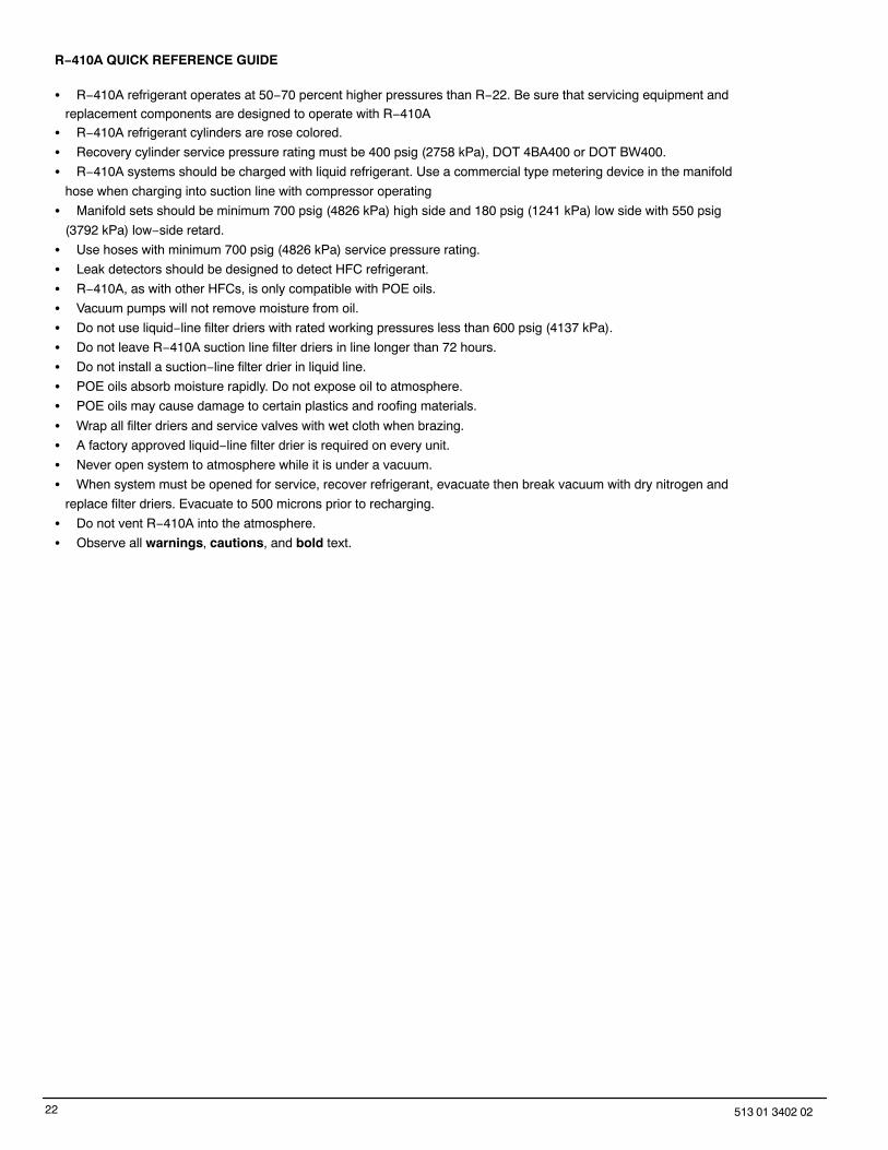
R−410A QUICK REFERENCE GUIDE
� R−410A refrigerant operates at 50−70 percent higher pressures than R−22. Be sure that servicing equipment andreplacement components are designed to operate with R−410A
� R−410A refrigerant cylinders are rose colored.
� Recovery cylinder service pressure rating must be 400 psig (2758 kPa), DOT 4BA400 or DOT BW400.
� R−410A systems should be charged with liquid refrigerant. Use a commercial type metering device in the manifold
hose when charging into suction line with compressor operating
� Manifold sets should be minimum 700 psig (4826 kPa) high side and 180 psig (1241 kPa) low side with 550 psig
(3792 kPa) low−side retard.
� Use hoses with minimum 700 psig (4826 kPa) service pressure rating.
� Leak detectors should be designed to detect HFC refrigerant.
� R−410A, as with other HFCs, is only compatible with POE oils.
� Vacuum pumps will not remove moisture from oil.
� Do not use liquid−line filter driers with rated working pressures less than 600 psig (4137 kPa).
� Do not leave R−410A suction line filter driers in line longer than 72 hours.
� Do not install a suction−line filter drier in liquid line.
� POE oils absorb moisture rapidly. Do not expose oil to atmosphere.
� POE oils may cause damage to certain plastics and roofing materials.
� Wrap all filter driers and service valves with wet cloth when brazing.
� A factory approved liquid−line filter drier is required on every unit.
� Never open system to atmosphere while it is under a vacuum.
� When system must be opened for service, recover refrigerant, evacuate then break vacuum with dry nitrogen and
replace filter driers. Evacuate to 500 microns prior to recharging.
� Do not vent R−410A into the atmosphere.
� Observe all warnings, cautions, and bold text.
23513 01 3402 02
Table 7 – Troubleshooting ChartSYMPTOM CAUSE REMEDY
Compressor and condenser fan will notstart.
Power failure Call power companyFuse blown or circuit breaker tripped Replace fuse or reset circuit breaker
Defective contactor, transformer, or high−pres-sure, loss−of−charge or low−pressure switch Replace component
Insufficient line voltage Determine cause and correctIncorrect or faulty wiring Check wiring diagram and rewire correctly
Thermostat setting too highLower thermostat setting below room tem-
perature
Compressor will not start but condenserfan runs
Faulty wiring or loose connections in compres-sor circuit Check wiring and repair or replace
Compressor motor burned out, seized, or Determine causeinternal overload open Replace compressor
Defective run/start capacitor, overload, startrelay Determine cause and replace
One leg of 3−phase power deadReplace fuse or reset circuit breaker
Determine causeThree−phase scroll compressor
Scroll compressor is rotating in the wrong di-rection
Correct the direction of rotation by revers-ing the 3−phase power leads to the unit.makes excessive noise, and there may be a
low pressure differential.
Compressor cycles (other than normallysatisfying thermostat).
Refrigerant overcharge or underchargeRecover refrigerant, evacuate system, and
recharge to capacities shown on ratingplate
Defective compressor Replace and determine causeInsufficient line voltage Determine cause and correct
Blocked condenser Determine cause and correctDefective run/start capacitor, overload or start
relay Determine cause and replace
Defective thermostat Replace thermostatFaulty condenser−fan motor or capacitor Replace
Restriction in refrigerant system Locate restriction and remove
Compressor operates continuously
Dirty air filter Replace filterUnit undersized for load Decrease load or increase unit sizeThermostat set too low Reset thermostatLow refrigerant charge Locate leak, repair, and recharge
Mechanical damage in compressor Replace compressor
Air in systemRecover refrigerant, evacuate system, and
rechargeCondenser coil dirty or restricted Clean coil or remove restriction
Excessive head pressure
Dirty air filter Replace filterDirty condenser coil Clean coil
Refrigerant overcharged Recover excess refrigerant
Air in systemRecover refrigerant, evacuate system, and
rechargeCondenser air restricted or air short−cycling Determine cause and correct
Head pressure too lowLow refrigerant charge Check for leaks, repair, and recharge.
Compressor IPR leaking Replace compressor Restriction in liquid tube Remove restriction
Excessive suction pressureHigh heat load Check for source and eliminate
Compressor IPR leaking Replace compressor Refrigerant overcharged Recover excess refrigerant
Suction pressure too low
Dirty air filter Replace filterLow refrigerant charge Check for leaks, repair and recharge
Metering device or low side restricted Remove source of restriction
Insufficient evaporator airflowIncrease air quantity
Check filter–replace if necessaryTemperature too low in conditioned area Reset thermostat
Outdoor ambient below 55�F (12.7�C) Install low−ambient kitFilter drier restricted Replace filter
24 513 01 3402 02
START−UP CHECKLIST(Remove and Store in Job Files)
I. PRELIMINARY INFORMATION
MODEL NO.:
SERIAL NO.:
DATE:
TECHNICIAN:
II. PRESTART−UP (Insert check mark in box as each item is completed)
( ) VERIFY THAT ALL PACKING MATERIALS HAVE BEEN REMOVED FROM UNIT
( ) REMOVE ALL SHIPPING HOLD DOWN BOLTS AND BRACKETS PER INSTALLATION INSTRUCTIONS
( ) CHECK ALL ELECTRICAL CONNECTIONS AND TERMINALS FOR TIGHTNESS
( ) CHECK THAT INDOOR (EVAPORATOR) AIR FILTER IS CLEAN AND IN PLACE
( ) VERIFY THAT UNIT INSTALLATION IS LEVEL
( ) CHECK FAN WHEEL, AND PROPELLER FOR LOCATION IN HOUSING/ORIFICE AND SETSCREW TIGHTNESS
III. START−UP
ELECTRICAL
SUPPLY VOLTAGE
COMPRESSOR AMPS
INDOOR (EVAPORATOR) FAN AMPS
TEMPERATURES
OUTDOOR (CONDENSER) AIR TEMPERATURE DB
RETURN−AIR TEMPERATURE DB WB
COOLING SUPPLY AIR DB WBHEAT PUMP SUPPLY AIR _____________________
ELECTRIC HEAT SUPPLY AIR _____________
PRESSURES
REFRIGERANT SUCTIONPSIG, SUCTION LINE TEMP*
REFRIGERANT DISCHARGE PSIG, LIQUID TEMP�
( ) VERIFY REFRIGERANT CHARGE USING CHARGING CHARTS* Measured at suction inlet to compressor
� Measured at liquid line leaving condenser.