Embed Size (px)
Citation preview
Installation - KI-1730D
Telecenter” V Diagnostic Program Version 16
Rauland-Borg Corporation Orig. 1 l/92. Rev. 7/94, 10/94,3/95,12/95 173004
Page 1 of 40

Telecenter@ V Diagnostic Program
a
Copyright 1992, 1994, 1995, Rauland-Borg Corporation, all rights reserved.
This document contains user’s information on technology that is proprietary to Rauland- Borg Corporation. Permitted transmittal, receipt, or possession of this document does not express license or imply any rights to use, sell, design or manufacture this information. No reproduction, publication or disclosure of this information, in whole or in part, shall be made without prior written authorization from an officer of Rauland- Borg Corporation.
ORauland-Borg Corporation
Printed in USA
Rauland-Borg Corporation Rauland-Borg (Canada) Inc. 3450 West Oakton Street 6535 Millcreek Drive, Unit 5 Skokie, Illinois 60076-295 1 Mississauga, Ontario, Canada L5N 2M2 (847) 679-0900 (905) 821-2225
Page 2 3/l 6/95

Telecenter” V Diagnostic Program
Table of Contents
General Information 1 ....................................................................................................... 5 Description.. ....................................................................................................................................................... 5 License for Use.. ............................................................................................................................................... 5 PC Requirements.. ........................................................................................................................................... 6
Getting Started 2 ............................................................................................................... 7 Backup Copy ..................................................................................................................................................... 7 Hard Disk Installation ..................................................................................................................................... 7 Connecting to the Telecenter V System.. ............................................................................................... 8
Running the TD5 Program 3 .......................................................................................... .9 Establishing a Direct Connection ........................................................................................................... 10 Connecting with a Modem.. ..................................................................................................................... 10 Exiting the TD5 Program ........................................................................................................................... 1 1
Terminal Mode 4 ............................................................................................................. 13 Terminal Mode Command Descriptions.. ............................................................................................ 13
Fl - Editor Selection ............................................................................................................................................. 13 F2 - Diagnostics.. ................................................................................................................................................... 13 F3 - Change Baud/Port.. ..................................................................................................................................... 13 F4 - Date/Time Functions.. ................................................................................................................................ 14 F5 - Phone Dialer.. ................................................................................................................................................. 14 F6 - Printer On/Off ................................................................................................................................................ 14 F7 - View Text File ................................................................................................................................................. 14 F8 - Edit Text File.. ............................................................................................................................................... 14 F9 - File Transfers .................................................................................................................................................. 14 F 10 - Redraw.. ........................................................................................................................................................ 14 Esc - Exit .................................................................................................................................................................... 14 ? - Help ....................................................................................................................................................................... 14
Editor Selection 5 ............................................................................................................ 15 Common Commands.. ................................................................................................................................ 16
F2 - External Program.. ........................................................................................................................................ 16
F4 - Block Status .................................................................................................................................................... 16 F6 - Load from Disk .............................................................................................................................................. 16
F7 - Save to Disk. ................................................................................................................................................... 16 F8 - Capture Data from TC5 ............................................................................................................................. 17 F9 - Send Data to TC5 ........................................................................................................................................ 17 F 10 - Print ................................................................................................................................................................ 1 7 Alt-F 1 - Select System Block ............................................................................................................................. 1 7
3/l 6/95 Page 3
Telecenter’B V Diagnostic Program
Ah-A - Architectural Editor ....................................................................... 18 F3 - Block Program.. .................................................................................. 19 F5 - Copy Previous.. .................................................................................. 19
Alt-C - Class of Service Editor.. ................................................................ .2Q
Alt-E - Time Based Events Editor.. ............................................................ .20
Alt-F - Call Forwarding Editor .................................................................... 21
Alt-l - PIN Code Editor.. ........................................................................... .21 F3 - Dialed Digits.. ..................................................................................... 22
Alt-L - Location Code Editor ...................................................................... 22
Alt-M - Intercept Table Editor.. ................................................................. .23 Entries.. .................................................................................................... 24
Alt-P - Call-in Prefix Editor.. ..................................................................... .25
Alt-S - Student Phone Editor.. .................................................................. .26
Alt-T - Toll Prefix Editor.. ......................................................................... .26
Alt-V - VCM Assignment Editor.. .............................................................. .27
Alt-X - Page Exclusion Editor ................................................................... .27
Diagnostics 6 .................................................................................... 29 Dump Active List.. .................................................................................. .29
I/O Diagnostic.. ....................................................................................... .30
Read Statistics ....................................................................................... .32
Logging ................................................................................................. .33
Appendix A ..................................................................................... .35 Voltage .................................................................................................... 36
F5 Phone Dialer ...................................................................................... .36
Preliminary Tests .................................................................................... .37
Appendix B ....................................................................................... .39 TD5 Command Line Arguments ................................................................ .39
Monitor Comrnands.. ............................................................................... .39
Miscellaneous CPU Monitor Commands ...................................................... 40
Page 4 3.!16195

Telecente? V Diagnostic Program
General Information 1 Description
The Telecenter Diagnostic Disk (TD5) is a configuration and diagnostic program used with the Telecenter V system. A PC based program, the TDS communicates with the Telecenter V system through a serial connection. This connection can be either a cable which directly connects the PC to the Telecenter V system, or through a pair of modems that are connected to the system.
The TD5 program enables a user to: J Edit configuration files on disk that are then downloaded to the Telecenter V system. J Retrieve the memory contents from a Telecenter V system for editing, diagnostics,
and archival. J Monitor system activity and acquires statistics maintained by the system. J Remotely analyze system performance. J Access system features for activation changes and troubleshooting.
License for Use The TD5 software and this manual are copyrighted by the Rauland-Borg Corporation, Skokie IL 60076. With the purchase and use of this software comes the following license for use: l The software may only be used to support Telecenter V systems. Using or copying
the software for any other purpose is a violation of Rauland-Borg’s copyright. l The software is to be used as described in this manual or as authorized by an
Rauland-Borg employee. Any other application of the software is a violation of Rauland-Borg’s copyright.
l The software and supporting files can be copied from the purchased diskette to any hard disk or other diskettes for supporting Telecenter V systems or for backup. No restrictions apply to the number of copies created from the purchased diskette for the purposes stated.
l This manual can be reproduced as needed for supporting Telecenter V systems. Distributing this manual for any other purpose is a violation of Rauland-Borg’s copyright.
3/l 6/95 Page 5

Telecenter@ V Diagnostic Program
PC Requirements The TD5 helps maintain Telecenter V systems and the related configuration data. In providing this capability, the program requires a minimum of 550K of usable memory (RAM). Many of the data editors functions are extensive and take a certain amount of processor time. Naturally, the program may seem slow on some computers. The minimum recommended PC configuration that would be used extensively for Telecenter V configuration and diagnostics is as follows: l 386SX desktop or laptop computer . I Meg memory (RAM) l 20 Meg hard disk l 3-l/2” low density diskette l Standard COM port
Although this is the minimum recommended configuration, the TD5 will run on a slower computer (including an IBM XT compatible) with 640K of memory and no hard disk. For emergencies, the software can be copied to 5-114” double density diskettes and used on computers without a 3-l /2” disk drive.
Page 6 3116195
Telecente? V Diagnostic Program
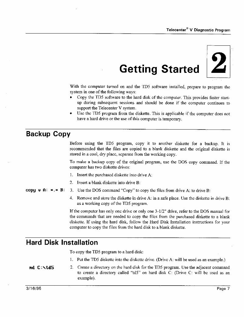
Getting Started 2 With the computer turned on and the TD5 software installed, prepare to program the system in one of the following ways: l Copy the TD5 software to the hard disk of the computer. This provides faster start-
up during subsequent sessions and should be done if the computer continues to support the Telecenter V system.
l Use the TD5 program from the diskette. This is applicable if the computer does not have a hard drive or the use of this computer is temporary.
Backup Copy Before using the TD5 program, copy it to another diskette for a backup. It is recommended that the files are copied to a blank diskette and the original diskette is stored in a cool, dry place, separate from the working copy.
To make a backup copy of the original program, use the DOS copy command. If the computer has two diskette drives:
1. Insert the purchased diskette into drive A:
2. Insert a blank diskette into drive B:
copy u A: *.* B: 3. Use the DOS command “Copy” to copy the tiles from drive A: to drive B:
4. Remove and store the diskette in drive A: in a safe place. Use the diskette in drive B: as a working copy of the TD5 program.
If the computer has only one drive or only one 3-l/2” drive, refer to the DOS manual for the commands that are needed to copy the files from the purchased diskette to a blank diskette. If using the hard disk, follow the Hard Disk Installation instructions for your computer to copy the files from the hard disk to a blank diskette.
Hard Disk Installation
md C:\td5
To copy the TD5 program to a hard disk:
1. Put the TD5 diskette into the diskette drive. (Drive A: will be used as an example.)
2. Create a directory on the hard disk for the TD5 program. Use the adjacent command to create a directory called “td5” on hard disk C: (Drive C: will be used as an example).
3/I 6195 Page 7

Telecenter@ V Diagnostic Program
copy A: *.* C:\td5 3. Copy the files from the diskette to the td5 directory on the hard disk.
PATH zPATtiz;c:\TD5 4. If you wish, add the td5 directory to the DOS PATH. In the autoexec.bat file, add the adjacent line.
This adds the td5 directory to the end of the DOS PATH. Older versions of DOS do not have this ability. Refer to the DOS manual for the syntax necessary to add the td5 directory to the DOS PATH.
Connecting to the Telecenter V System To connect to the Telecenter V system, there must be a hardware connection between the PC’s COM port and the Telecenter V serial port. If the PC and the Telecenter V system are in close proximity, a direct connect can be used. If the connection is remote, a pair of modems should be used. See Appendix A for cabling instructions and modem requirements.
Page 8 3116195

Telecente? V Diagnostic Program
Running the TD5 Program 3 , I
To use the TD5 program from a diskette, log onto that diskette drive. To do this, type the drive letter and a colon at the DOS prompt, then press Return.
To use the TD5 program from the hard disk without the td5 directory on the PATH, change the default directory to the td5 directory by typing cd ltd.5.
After changing the drive or the directory, enter TD5 (or, if your PC supports VGA graphics, you can run the program in the 43- or 50-row mode by typing TD5/43 or TDY50, respectively). The first screen of the TD5 program appears, as seen in section 1 of the example below.
FB-Change Bau
C Terminal Mode 1 te/Time Functions F7-View text file FlB-Redraw one dialer
urn printer ON FP-Fi le Transfer Fb-Edit text file E3ff;:;it
- - -~~ -- 0. ND CPU CONNECTED 1. con1: t 1
I 2. conz: 3. cLM3:
;+l 4. CDH4:
Choose new baud rate: 0. 300 baud I 1. 1200 baud 2. 2480 baud 4-2 3. 4800 baud 4. 9600 baud
con 1 ran. - -- ~~-~ ~. BAUD 9680 Looking for Ielecenter . . . I-3 ~
felcccnter U detected. 0000 : 03FE
The number of COM ports displayed depends on the configuration of the individual PC.
If there is no hardware connection to the Telecenter V system, press 0 or Esc to use the TD5 program in a stand-alone mode. If there is a hardware connection, press the number of the COM port that is connected.
3/l 6/95 Page 9

Telecenter@ V Diagnostic Program
Establishing a Direct Connection After selecting a COM port, the prompt for a baud rate selection appears (refer to section 2 in the above example). Choose 4 to select 9600 baud.
The TD5 program tests for a Telecenter V system, reports the results, and enters the Terminal Mode. If the TD5 finds the CPU, then the TD5 returns the message Adjusting Telecenter's Baud Rate. Once adjusted, the Telecenter system responds with Telecenter V detected (refer to section 3 in the above example). The program will send everything typed in the Terminal Mode to the Telecenter V system, and everything the Telecenter V system receives is displayed on the screen.
If the TD5 program cannot establish communication with the Telecenter V system, the program responds with Unable to communicate. Returning to the terminal mode. Check the cabling and press F3 to restart this process.
Whether the serial connection is direct or through modems, press the Space bar in the Terminal Mode to verify communication with the system. If there is a connection, a space and two additional characters appear on the screen. These characters are from the Telecenter V monitor program. Type a : ) to view a set of commands that the system recognizes. See Appendix B for a list of the monitor commands that are used in the Terminal Mode.
Connecting with a Modem After a COM port is selected, a prompt for a baud rate appears. Select the number for a baud rate that matches the baud rate of the modem attached to your PC. See Appendix A for modem configuration requirements.
The TD5 program tests for a Telecenter V system or a modem, reports the results, and enters the Terminal Mode. If a modem is detected, the TD5 will respond with the message Modem detected.
The Terminal Mode directly controls the modem for dialing. Refer to the modem’s operating manual to determine the necessary key sequence.
AT<RETUIRN> With a Hayes compatible modem type the sequence shown to the left.
If the response OK does not appear, check the cabling and baud rate selection. When the modem does respond, continue with this procedure.
ATDT5551234 Enter the ad.jacent sequence.
This sequence uses tone dialing to dial 555-1234. If the modem connected to the
CONNECT 2400 Telecenter V system is properly configured, it automatically answers and the two modems establish communication. A message similar to that shown to the left.
Page 10 3116195

Telecente? V Diagnostic Program
There is now a serial data link from the PC through the modems to the remote Telecenter V system. Once the connection is established, press F3 to adjust the systems serial port.
If the TD5 program has trouble establishing communication with the Telecenter V system, press F3 to restart this process. It is important to select the same baud rate as the modem attached to the PC.
With a Hayes compatible modem, use the following procedure to terminate the connection: l pause for 3 seconds . enter “+++” l wait 2 seconds for an OK response 0 enter A TH
Whether the serial connection is direct or through modems, press the Space bar in the Terminal Mode to verify communication with the Telecenter V system. If a connection exists, a space and two additional characters appear on the screen. These characters are from the Telecenter V monitor program. Type a ? to show a set of commands that the Telecenter V recognizes. See Appendix B for a list of the monitor commands that are used in the Terminal Mode.
Exiting the TD5 Program To exit the TD5 program, press Est. If changes have been made to the configuration, the TD5 confirms the exit request with:
C Terminal Mode 1 Exit ID5 (Y/NJ?
If the changes have been saved to a file or downloaded to the Telecenter V system, press Y. To save the changes at this time, press N and the TD5 will return to the Terminal Mode.
If there are no changes, the TD5 exits and returns to DOS.
3116195 Page 11
Telecenter’ V Diagnostic Program
Terminal Mode 4
C Terminal Mode 1 Fl-Editor Select ion F4-Date/Time Functions F7-View text file FlB-Redraw FP-Diagnost lcs FS-Phone dialer FB-Change Baud/Port F6-Turn printer ON FP-File Transfer -
F8-Edit text file FSi;F;it
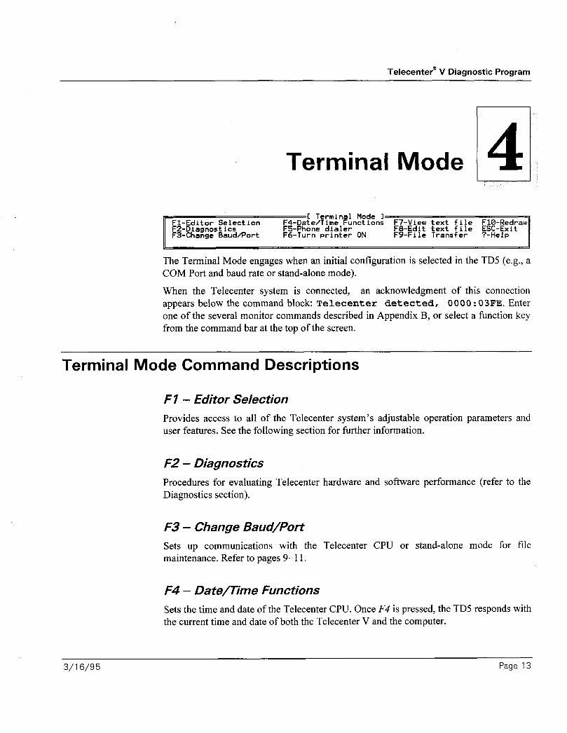
The Terminal Mode engages when an initial configuration is selected in the TD5 (e.g., a COM Port and baud rate or stand-alone mode).
When the Telecenter system is connected, an acknowledgment of this connection appears below the command block: Telecenter detected, 0000: 03FE. Enter one of the several monitor commands described in Appendix B, or select a function key from the command bar at the top of the screen.
Terminal Mode Command Descriptions
Fl - Editor Selection
Provides access to all of the Telecenter system’s adjustable operation parameters and user features. See the following section for further information.
F2 - Diagnostics
Procedures for evaluating Telecenter hardware and software performance (refer to the Diagnostics section).
F3 - Change Baud/Port
Sets up communications with the Telecenter CPU or stand-alone mode for file maintenance. Refer to pages 9-11.
F4 - Date/Time Functions
Sets the time and date of the Telecenter CPU. Once F4 is pressed, the TD5 responds with the current time and date of both the Telecenter V and the computer.
3/l 6/95 Page 13

Telecente? V Diagnostic Program
Choose one of the selections in the example above. If 2 is pressed, the TD5 prompts for hours, minutes, month, date, and year. Choice 3 toggles the current time between military and AM/PM modes. Press Esc to return to the Terminal Mode.
F5 - Phone Dialer
Autodial feature built in for modem communications. See Appendix A for further description.
F6 - Printer On/Off
Records monitor sessions with a printer. Printouts of the system programming can be made through the respective editor screens.
F7 - View Text File
Views any DOS text file (e.g., file headers, help files).
F8 - Edit Text File
Modifies or creates TD5 DOS text files (e.g., headers, help files, phone directory, etc.).
F9 - File Transfers
Copies portions of the Telecenter system’s memory for analysis.
FIO - Redraw
Refreshes the screen when corrupt characters are received from the communications link.
Esc - Exit
Exit the TD5 program.
7 - Help
Provides a summary of the Terminal Mode commands. See Appendix B for further descriptions.
Page 14 3/16/95

Telecente? V Diagnostic Program
Editor Selection 5 C Terminal Ilode 1
ALT-A firchitectural Editor ALT-I PIN Code Editor ALT-S Student Phone ALT-C Class of Seruice Ed. RLT-L Location Code Editor ALT-T Toll Restriction ALT-E Time Based Euent Ed. FILT-II Intercept Table Ed. RLT-U UCH Assignment ALT-F Call Forwarding Ed. FILT-P Call-in Prefix Ed. ALT-X Page Exclusion EI
Editor Selection shows each of the special editors (Ah-‘key’) available to set features of the Telecenter V system. This FI summary exists in each special editor screen. Once the special editor keys are learned, they are available from any screen without pressing FI first. The Alt keys are recognized any time an Editor or Terminal Mode awaits input.
Press FI to display a menu of editors and their key sequences. The title that appears at the top of the menu is the same as the editor from which the menu was activated. The above example was created in the Terminal Mode.
To select an editor, press and hold Alt and then press the corresponding letter.
The following list briefly describes each of the twelve editors. Detailed descriptions of the editors are in the sub-sections that follow.
Note: For more l
information on SMDR, refer to the Telecenter Programming manual l
(ICI-1692).
l
Alt-A Architectural: Assigns port information and zone programming to each of the physical lines in the system. Alt-C Class of Service: Defines and groups the operational characteristics for each line type in the system. AH-E Time Based Event: Utilizes the Telecenter system’s internal clock to switch between the system’s (memory) blocks (l-4) and to control the student phone. Alt-F Call Forwarding: Allows the technician to assign, modify, and delete station forwarding assignments. AH-I PIN Code: Allows the technician to assign, modify, and delete Personal Identification Numbers. Alt-L Location Code: Sets global and external peripheral equipment features including; trunk timing and routing, console key appearances, system dialing parameters, Station Message Detail Recording (SMDR), and call-control timings. Al&M Intercept Table: Assigns single-digit dialing for each line type (Class of Service). Assignment includes type of line hunt, echoing of digits dialed, and Uniform Dialing Plans. Alt-P Call-in Prefix: Provides a method of assigning a string of five characters to accompany architectural information about a call-in. Refer to the r attribute setting in Class of Service. Alt-S Student Phone: Sets Telecenter system access for “outside only” type of service. No dialing of trunk access digits is necessary.
3116195 Page 15

Telecenterw V Diagnostic Program
l Alt-T Toll Restriction: Allows the restriction of any or all central-office prefixes. l Alt-V VCM Assignment: Assigns switch banks to the physical LLM port associated
with the individual intercom channel. l Alt-X Page Exclusion: Mutes individual speakers by physical number during zone,
all-call, or time-tone pages.
Common Commands
Fl-Editor Selection F¶-Block Status F'I-Saue to Disk FlWPrint FZ-External Prog F5-Not used FE-Capture from IC5 F3-Not used Fb-Load From Disk FV-Send Data to TC5 ALT-Fl-Select System Block ALI-FZ-Copy System Blocks
Note: u conlplete
TCV tmw7onj,file
shodd con&in
upproximately
33K &es of if7fi,nnution.
Sending smaller ,files results in cormpt
configwulion
progrutnming.
All feature editors display a menu of the commands (function keys) available within the editor. Many of these commands are the same for all the editors. Above is an example of a menu with the editor specific commands, F3 and F5, removed. The remaining function keys: FZ. F2, F4 and F6 through FZO have a common purpose between each of the data editors. The following sections describe these function keys.
F2 - External Program
F2 executes an external supplemental program that helps troubleshoot hardware and find configuration errors.
F4 - Block Status
F4 displays memory blocks and their status. As data is modified, the TD5 tracks the changes so that only those changed areas are transferred to the Telecenter V system. The Telecenter system’s memory is divided into 256 blocks of information. The status of each block is represented by one of the following characters:
-I- valid block, same as in the CPU3.
invalid block, not yet read from the CPU3.
* modified block in PC memory, but not sent to the CPU3.
F6 - Load from Disk
F6 loads the configuration file from the disk. Use the cursor keys to highlight the desired file and press Enter. To enter a new directory, press E?srer while highlighting that directory.
F7 - Save to Disk
Press F7 to save to a disk. Use the cursor keys to highlight an existing file or enter a new file name. Information such as date, school name, users name. and special features of the
Page 16 3116195

Telecente? V Diagnostic Program
Note: Files saved that system should be included. Function key commands are listed at the bottom of the
contain “invalid screen. Press F7 to exit the editor. Use the View File function to display this
blocks” should not be information from DOS or the Terminal Mode. sent back to the Telecenter system ‘s CPU. F8 - Capture Data from TC5
F8 transfers all memory space in the Telecenter V system. Use this function when saving TCV’s memory to a file. Press Esc at any time to abort the transfer.
F9 - Send Data to TC5
F9 transfers modified memory blocks to the Telecenter V system. Press Esc to abort the transfer.
F70 - Print
FIO prints specific information from each editor. In some editors, it is necessary to enter a range to be printed. For example, the Architectural Programming Editor prints the architectural programming for a range of physical numbers and sends the data to a printer or file.
If using a printer, follow the prompt and align the paper in the printer. Press any key to begin. If printing to a file, enter the file name at the prompt.
Press Esc at any time to abort the printing operation and return to the data editor.
A/t-F7 - Select System Block
The Telecenter V system uses an area of memory called a system block to store configuration information. Up to four system blocks can be allocated for different configurations. The TD5 edits one system block at a time. For a Telecenter V system that uses multiple system blocks, be certain which system block is to be edited. The editor screens display, in the lower right hand corner of the screen, the system block currently being edited.
The following screen appears:
System block currently edited: 0
Number of system blocks currently allocated: 4
System block currently actiue: 3
When additional system blocks are allocated, the contents of these blocks are copied from an existing system block. If there is only one, its contents are used automatically. If
3/16/95 Page 17

I.2
Telecenter V Diagnostic Program
Note: this feature is only usable qfter nmltiple blocks have been allocated. Perform this function carefull?; so as not to inadvertently destroy the contents qfthe target system block.
there is more than one. designate which system block is to be copied into the new system blocks.
After selecting a new block to edit, press Esc to return to the last editor selected and update the work space with the information from the new selected block. To exit the Select System Block command, select any other block.
A/t-F2 - Copy System Blocks
Al/-F2 allows a system block to be copied from any other block. Shown below is the screen displayed.
=L System Block Allocation I= 4 system blocks auailable
Copy from block to block
Alt-A - Architectural Editor - --
-C Architectural Editor I- Fl-Editor Selection F4-Block Status F7-Save to Disk F2-External Program FS-Copy Prev Attribs F8-Capture from TC5 F3-Block Program F&Load from Disk FS-Send Data to TC5
UHQ;P;i nt
<ALT>Fl-Select System Block <ALT>F2-Copy System Blocks
Phys No
Is ADfl?N PHONE
1 1
Arch -
i II
Hunt Class Zones
Use the arrow keys to move among the data f?elds. For each ph~~sical line connected to the Telecenter V system. assign an architectural number. htlnt status. class of ser\-ice. and paging zones. For ref’erencc. a class of ser\,ice summary appears at the bottom of* the screen for the physical line curreiitl>~ being edited. M’hen J 011 run the Diagnostic
Page 18 3/I 6195

Telecente? V Diagnostic Program
Program in the 80 (columns) x 50 (rows) or 80 x 43 mode (see Appendix B), the Architectural Editor shows, in the box for the A attribute, the line type of the highlighted physical number (in the above example, “Admin Phone”). The attributes are defined using the Class of Service Editor (Alt-C). The definition of each field is as follows: l Phys No: The position of the physical number. Enter a new number to advance to
that line position. l Arch: Enter a three or four digit number to change the architectural (dialing) number
for this line. l Hunt: Defines the hunt characteristics for calls delivered to this line. Press I to
toggle the setting of this field. When the field is set to 1 and the line is busy, calls are routed to the next physical line.
l Class: Defines the type of service provided for a line. There are 64 classes of service that are defined or altered by using the Class of Service Editor (Alt-C).
l Zo nes: Defines the time tone and paging zones that activate the speaker associated with the line. Press 2 through 8 to toggle the status for each of the 8 zones.
F3 - Block Program
This function copies the architectural information of the highlighted line to a range of lines. Enter the range of lines in the prompt box.
The TD5 asks which fields are to be altered (NJ, s, 2:) Press the appropriate keys to toggle the letters on and off until the desired combination is reached. Only the fields set are included in the block changes made. The attributes (if enabled) are duplicated throughout the specified range. The architectural numbers are automatically numbered sequentially if the N field is included in the Block Program command.
F5 - Copy Previous
F-5 copies the attributes of the preceding line to the highlighted line. In this editor, the architectural number of the highlighted line is automatically incremented.
Press Esc to exit this menu and return to the Terminal Mode.
3/l 6195 Page 19

Telecenter@ V Diagnostic Program
Ah-C - Class of Service Editor
Refer to the Telecenter V Programming Manual (KI-1692) for detailed information regarding Class of Service attributes and display call-in routing options.
Characteristics of each Class of Service are defined by the contents of the A, B and C
attributes with the r0, rl, r2 and r3 display routing options. Use the cursor movement keys to change specific fields for each Class of Service attribute. In fields A, B, and C,
press digit keys 1-8 to toggle the settings. The following fields describe the r attributes for the call-in routing options: l D - display address. Valid values are 0 through 15. Use 31 for no display. 16
through 30 are reserved for future use. l L - priority level for call-ins. A valid range is 0 through 3, 0 being the lowest
priority. l P - call-in prefix. Valid values are 0 through 7. Use the Call-in Prefix Editor (AZ&P)
to review or modify the prefixes. l : - press I through 3 to toggle the settings. Only setting I, remote cancel of call-
ins, is available at this time
Ah-E - Time Based Events Editor
C Time Based Euents Editor 1 Fl-Editor Selection F4-Block Status F7-Save to Disk FlO-Print F&External program FS-Copy Preu Item F&Capture from KS F3-Sort by Time F6-Load from Disk FS-Send Data to TC5 Del-Delete Record RLT-Fl-Select System Block RLT-FZ-Copy System Blocks
Item Time Euent
Page 20
The events list is a global feature, therefore, the system block message on the bottom of the screen will not appear. The system will hold up to forty time-based events. F3 sorts the list by the time. F5 copies the previous setting.
3116195

Telecente? V Diagnostic Program
Page Up, Page Down, and the arrows move the cursor through the fields. Delete eliminates any highlighted event. The time must be entered in a 24-hour (military) format (e.g., 6:00 pm is 18:OO). Valid event numbers are as follows: l I through 4 selects system blocks 1 through 4. l 5 enables Student Phones. l 6 disables Student Phones.
Ah-F - Call Forwarding Editor
C Call Forwarding Editor 1 Fl-Editor Selection F4-Block Status F7-Save to Disk FIB-Print F&External Program FS-Copy Preu Item FB-Capture from TC5 ?-Help F3-Block Program FC-Load from Disk FS-Send Data to TC5 ALI-Fl-Select System Block RLT-FZ-Copy System Blocks
Phys Arch Forward no answer Forward if busy Forward always
15 415 416 416 0 lb 416 0 418 0 17 417 0 0 416 16 418 0 0 0
The Call Forwarding Editor lists all physical numbers with their associated architectural number. Three columns report the call-forwarding information. The user may alter, add, or delete any information within the three columns by using the arrow keys to move between the fields. Enter a valid architectural number into one or more of the forwarding fields to define call forwarding for that line. Enter 0 in any of the three fields to set no forwarding for that line. Like the A&-A or Ah-L screens, enter any valid physical number in the Phys field to go to that number in the call-forwarding table.
Alt-l - PIN Code Editor
F3-Set Dialed Digits F&Load From Disk
Index 0 1
Physical Line 16 18 25 40
PIN 1616 IBIB 2525 8451
When entering the PIN table for the first time-if no PINS have been assigned-only the table headings appear in the workspace under the command block. Press Insert to insert the first and subsequent PIN definitions. A new PIN entry has a physical line of 0 and a
3/l 6195 Page 21

Telecente; V Diagnostic Program
PIN number of 0. Use the arrow keys to review or define the PIN numbers for the physical lines desired. Press Delete to erase the highlighted entry.
F3 - Dialed Digits
The number of digits set for PINS is 4
Enter the number of spare PINS to allocate:
F3 defines the length of the PIN numbers or disables the use of PINS. If PIN numbers are defined as 4-digit and the PIN length changes to 3-digit, then the entries cannot be used and must be changed. Select 0 to disable the PIN feature. After the number of digits have been selected, the TD5 asks for the number of spare PINS. This reserves memory space for the input of PINS from individual phones. See the Telecenter V Operations Manual (KI-1693) for more information.
Ah-L - Location Code Editor
C Location Code Editor 1 Fl-Editor Selection F4-Block Status F7-Save to Disk FlB-Print FZ-External Program FS-Copy Preu Lot FB-Capture from TC5 F3-Not Used F&Load From Disk FS-Send Data to TC5 ALT-Fl-Select Block ALT-FZ-Copy Blocks Space-Help on itmes with * or "
*mi$ 3 3 or 4 Digit Dialing * 60 Dial Tone Time Limit C68=1 SEC) * 64 65 Hook Flash Time Limit [60=1 SEC) * 66 cl Attendant, Hotline, or TC4400 * 68 12Ul Attendant ring-back time C60=1 SEC)
The Location Code Editor allows global configuration changes for the Telecenter V system. Careful consideration must be taken so as not to create configurations that limit the system’s operation and performance.
This editor limits the changing of location codes 60 through 1342. Other areas of the system’s memory are programmed and managed by the various ‘I’D5 data editors. Refer to the Telecenter V Programming Manual (KI-1692) for complete information on
location codes. their options and default value settings. Press the Space bar while the cursor is on an * or ” for additional descriptions of the location code and valid settings After viewing the Help file press any key to continue.
Use the arrows, Page Up. Pqe DOMV~. Hor77c and Er7d keys to move within this screen. Enter a valid location code number into the Lot Code number field to advance to that code.
Page 22 3116195

Telecente? V Diagnostic Program
Ah-M - Intercept Table Editor C Intercept Table Editor 1
Fl-Editor Selection F4-Block Status F7-Saue to Disk FIO-Print F&External Program F5-Insert New F&Capture from TC5 Ins-Insert New F3-Not Used F6-Load From Disk FS-Send Data to TC5 Del-Delete Cur FtLT-Fl-Select System Block ALT-FZ-Copy System Blocks
CDS Digits Trunks or t fiction Hunt Pre-sequence 1 Q-Q 100-101 Norm Linear 1 9-9 13-15 Norm Linear 9,
22 Q-Q 100-101 Norm Linear 22 9-9 13-15 Norm Linear 3,
The Intercept Table traps digits dialed from a users phone and connects that party to a physical line (trunks or numbers) specified in the table. The entry instructs the system how to process the call once a connection has been established. The Telecenter V system’s flexibility in processing calls, for interconnect and other purposes, allows transparent operation to external systems.
The workspace is divided into five fields by logical sequence of call processing. A complete description of each field is listed below:
Class of Service: The Class of Service number (l-63) of the line that dials the digits the intercept table will trap.
Digits: Tells the system what digit or range of digits to capture. Do not use digits that are programmed as first digits in an architectural number (e.g., digit range 4-4 will prevent the Class of Service specified from dialing room numbers 403, 422, etc.) The Uniform Dialing Plan is used to specify larger ranges for access to external PBXs and Centrex Service (such as 630-699). The Universal Dialing Plan digit range cannot exceed the Telecenter V system’s number of digits for system dialing (e.g., In three digit dialing, Universal Dialing Plan’s maximum digits are three).
Digit range also provides the dialed number used to access the Alternate # Mapping feature (e.g., the digit range 500-500 can specify #OO, all page, where #00 is placed in the Trunks or # field). Although the Alternate # Mapping feature is valid for all Class of Services, system restriction (B attributes) still applies.
Trunks or #: Instructs the Telecenter system which physical number (trunk) or range of physical numbers to connect the calling party to. For Alternate # Mapping, this field describes the function to access when capturing the digits specified within the Digits field.
Action: Informs the Telecenter system how to terminate the operation when the calling party is connected to the designated physical number. Here is a list of available options:
Norm (N) : When the calling party is connected to the physical number or trunk-terminate operation.
3116195 Page 23

Telecenter’ V Diagnostic Program
Echo (E) : Echoes the captured line to the trunk port prior to sending the stored digits the user has dialed.
Arch (A): Echoes the architectural number of the calling party to the connected port (physical number) prior to sending the dialed digit.
Phys (P): Echoes the physical number of the calling party to the connected port prior to sending the stored digits the calling party dialed.
UDP (U): Uniform Dialing Plan instructs the Telecenter system to redial the set of digits captured to the physical number or trunk seized.
Cut (C): (Version 308.0 and later ONLY) Cut Through allows a pre-sequence string to be sent out across the tie line and then enforce the PBX dialing restrictions while the audio is cut through to the calling line.
Note: The remote Remote Extension (R): (Version 401.0 and later ONLY) Allows the system to extension may have a longer number (more
accept n digits after the intercept to be forwarded to the remote system.
digits) than the To access the REMn function, move the cursor to the Action field in the architectural numbers of Intercept Editor and press the spacebar until the desired action appears. Telecenter extensions. If the Alternate # Mapping feature is used, no entry in the action field is required.
Hunt Status: Describes how the system should search for an available line designated in the Trunks or # field. The choices, Linear (most common) begins with the lowest physical number in the search, and Rotary marks the last place the call was connected to and increments it by one for the next intercepted call.
Pre-sequence: (Version 308.0 and later ONLY) Specifies a dialing string that is to be transmitted over the target line (via DTMF) before any other digits are sent, and before the audio is cut through to the dialing instrument. The permissible characters in the pre-sequence are the digits (O-9) , (*) , and (#). A comma (,) may be used to insert a delay equivalent to the delay defined by Location Code 72 (wait for external dial tone).
En tries Initially the screen shows no intercepts. Press Insert to add the first entry, which has the following form:
Class of Scru ice Digits Trunks or u Action Hunt Status I - 8-O HOPm Linear
Subsequent inserts create a new entry and copy the data from the highlighted line.
In the Class of Service field, enter a value between 2 and 63 or press the Space bar to advance to the next Class of Service. The Space bar is helpful when entering an intercept for a series of Class of Services. A sequence of “Insert, Space, Insert, Space, . . . ” creates a sequence of Classes of Service with common characteristics.
Use the arrow keys or Return to move among the fields. Delete erases the currently highlighted line.
Page 24 3/l 6/95

Telecenter” V Diagnostic Program
In the Digits field, the editor accepts up to 4 digits, unless the system is set for 3-digit dialing. If this is the case, simply enter fewer digits.
The program will not accept digit or trunk ranges that overlap within a Class of Service or between two Classes of Service. For example, if the entries are 100-120 and 120-130, 120 conflicts as it is common to both ranges. This must be resolved before saving or exiting. The type of error appears in the status bar at the bottom of the screen.
A less obvious conflict can occur between Classes of Service. Digit ranges can match between two Classes of Service, but not in any other way. For example, Class of Service 1 may have digit range 1 OO- 120; Class of Service 2, lOO- 120; and Class of Service 3, 100-121. Classes of Service 1 and 2 do not conflict, but Class of Service 3 does since 121 is not common to the other Classes of Service. To continue, split Class of Service 3 into two entries such that the first entry has the digit range 1 OO- 120 and the second has the digit range 12 l- 12 1. Use this technique to resolve all overlapping conflicts that might occur.
In the Action and Hunt fields, use the Space bar to toggle the settings.
Alt-P - Call-in Prefix Editor
refix Editor 1
Prefix 0 m Prefix 1 EHEB Prefix 2 DOOR Prefix 3 BUSES Prefix 4 GYH Prefix 5 SHOP Prefix 6 WINElI Prefix 7 HALL
The Call-in Prefix Editor assigns up to five characters to proceed the call-in architectural number sent to a Vacuum Fluorescent Display (VFD) and/or Side Car Display. Prefix assignment and display addressing information is provided in the r attributes section of KI-1692.
In the above example several popular options are shown. Enter the desired Call-in Prefix strings using any keyboard character. Use the arrow keys to move up or down the field. F3 sets the prefixes to the factory default setting (only Prefix 1 is set to Emer).
3/l 6/95 Page 25

Telecenter@ V Diagnostic Program
Alt-S - Student Phone Editor
C Student Phone Editor 1 Fl-Editor Selection F4-Block Status F?-Save to Disk FIB-Print FZ-External Prog F5-Not used FE-Capture from TC5 F3-Not used Fb-Load From Disk FV-Send Data to TC5 flLT-Fl-Select Block ALT-F2-Copy Blocks
Naximum length of student phone call: 60 seconds Duration to preuent same number: 30 seconds Access code for outside trunk line: 9
The Student Phone Editor sets parameters for the student phone such as duration of call, time limit to prevent the number from being recalled, and system outside-access digit. The three statements displayed must be set for proper operation. In the first field, enter the length (in seconds) of the student phone call. An entry of 30 limits the call to 30 seconds. Valid entries are 0 and 30 to 180 seconds, with 0 allowing an unlimited length of student calls. A warning beep is given ten seconds prior to disconnect. The second field is set in minutes. Valid entries that restrict the same number from being called are I through 60. Entering a 0 does not restrict the numbers from being redialed. In the third field, enter the single-digit trunk access code. This code must also appear as a digit range in the Intercept Editor (M-M) for each student phone Class of Service. F3 sets the student phone to factory default settings (e.g., duration seconds, redial minutes, access digit 9). Use the arrow keys to move down the fields.
Alt-T - Toll Prefix Editor
C Toll Prefix Editor 1 Fl-Editor Selection F4-Block Status F7-Save to Disk FlO-Pr int FB-External Program F5-Restrict All Prefixes FE-Capture from TC5 F3-fillow All Prefixes Fb-Load from Disk FV-Send Data to TC5 ALT-Fl-Select System Block FILT-FZ-Copy System Blocks
208 - 209 & 2iil 2;2 2;3 2i4 2;5 2:b 2:7 2:S 2;V 218 - 219 --- 211 --- 213 --- 215 --- 217 --- 219 220 - 229 220 --- 222 --- 224 --- 226 --- 228 --- 230 - 239 --- _-- -__ --_ --- _-- ___ -__ --- __-
The Toll Prefix Editor restricts individual central office prefixes from being dialed by a Class of Service with a B:l attribute only (no B:2). For Classes of Service with both B: 12 attributes set, these restrictions do not apply. The prefix is restricted when “---“ appears. F3 and F.5 allow and restrict, respectively, all prefixes from being dialed. Use the arrows, Page Up, and Page Down to move within the fields of the prefix table. The Space bar toggles the highlighted prefix between restricted or allowed.
Page 26 3/l 6195

Telecente? V Diagnostic Program
Note: When a Class of Service is restricted to local access only, the user may dial 7 digits (3 digit prefix and 4 digit address) or “1” plus 7 digits. In some states or provinces served only by one area code, “1” plus 7 digits is considered long distance. In these applications, the installer must allow only the prefixes not considered long distance or that the user deems necessary for staff access. Special 3 digit service codes provided by the local telephone company must also be allowed in the Toll Prefix Editor (e.g., 911, 611, and 411). The Class of Service without the B:2 attribute may make calls to three other area codes specified in location codes 228, 230, and 232. Refer to the Telecenter V Programming Manual (IQ- 1692).
Alt-V - VCM Assignment Editor
Note: The VCM table must agree with the system ‘s S-Bus wiring.
C UCH Assignment Editor 1 Fl-Editor Selection F4-Block Status F7-Save to Disk FlD-Pr int FZ-External Prog F5-Not Used F&Capture from TC5 F3-Default F&Load From Disk FS-Send Data to IC5 ALT-Fl-Select System Block ALI-F2-Copy System Blocks
SC25 UCH Ej ;
1 2
The VCM Assignment Editor tells the system which physical line to access when making an intercom call to a speaker. The system can have up to 21 separate VCMs (or channels), one per switch bank (SC2S) or relay module (TC4 11 O/20/30).
The SC25 field is indexed at 48 and 0 through 19. This field cannot be modified. The VCM field accepts any valid physical number (2 or 4 through 511). F3 sets the VCM table to the default setting of physical line 2 for all SC25s. The arrows, Page Up, Page Down, Home, and End keys move the cursor through the table.
Alt-X - Page Exclusion Editor
II Index I Physical Line Flrch Num I II
3116195
The Page Exclusion Editor enters a list of speakers that are to be excluded from receiving zone pages, all-call pages, and time tones. This feature is handy for multiple programming blocks (e.g., Night Mode, Vacation days). The table does not provide page originator speaker exclusion (a global setting, see Location Code 506).
Page 27

Telecenter’ V Diagnostic Program
There are three fields provided: Index, Physical Line, and Architectural Number. The Index keeps a running total of the amount of entries. As new entries are made, the TD5 resorts the table. Entries are created or removed by using Insert or Delete, respectively. After pressing Insert, the TD5 responds with O’s in all three fields. Modify the physical or architectural number by entering a digit in the appropriate field. Press Enter and the associated physical or architectural number appears in the corresponding field. Once the table is established, use the cursor movement keys to view or locate any entry.
Page 28 3/l 6195

Telecente? V Diagnostic Program
Diagnostics
Press F2 in the Terminal Mode to select Diagnostics.
The following menu appears:
ESC Return to main menu 1 Dump actiue 1 ist 2 Read statistics 3 I/O diagnostic 4 Logging
Choose one:
6
Dump Active List Note: The architectural
temporarily leave the
number associated with
AL Dump function and
each active line appears on the right half of the
Diagnostics and enter
line, ifavailable in local PC memory. If the information is
the Architectural
unavailable, dots are shown. To add the missing information,
This function takes an instantaneous snapshot of the activity of lines in the Telecenter V system. At the start up, an empty list appears at the top of the screen, along with the
l
reverse video menu. The choices available within this process are listed below: l
[up arrow, down arrow] - Moves the reverse video bar up and down the screen to
G - Get new active list data. l
select records or scroll additional records onto the screen. The number of the
S - Save the present active list in an ASCII file to be printed or studied at some later time.
highlighted record always appears in the upper right corner of the screen.
l Esc - Exits from the AL Dump program. If the AL Dump diagnostic is re-entered while the program is still running, the same data will appear until another Get cycle (G) is performed.
functions (Fl). Obtain --
the datafiom either a 4 cc F@ s’
4403 ADMIN PHONE 123456
disk or the Telecenter V ; 4404 ADMIN PHONE 123456 4407 ADMIN PHONE 123456 2
svstem bv disulavinP or .A 4415 DIALING STF 1 7
. . . . . . . . . . . . . . . . . . . . . . . . . . . . . . .
, / 1,”
capturingfiom within is 1025
<end of acf)iveYZ)t > SVSCLJ
the Architectural menu.
An example of active list entry is:
sline: The Phys number that the record describes. Records are ordered by the Phys number.
oline: The object physical number which is the physical number of a called line. This field may also be used to store other information when OLINE: data is not
3/l 6195 Page 29

Telecenter” V Diagnostic Program
needed. (Call-ins don’t have object physical numbers).
param: The parameter field which contains data used by the control program. It is generally not relevant in troubleshooting.
proc: The procedure name for most functions. It may contain letters or numbers. All supervisory functions begin with sv : and are listed below:
svphone: Administrative phone or multi-link staff phone in use.
svinter: Outside line in use, AAI, DIL type.
svdia: Outside line in use, DISA type.
svspeak: Speaker in use for communication.
svsc25: This means that at least one 4 110, 4 120, or 4 130 speaker relay board is being supervised by a telephone for paging or tone signals.
These functions are used when a communication path has been established while waiting for a disconnect. Some other PROCs are:
parse0: , parse1 : Receiving DTMF tones aband: Administrative phone abandoned by the receivers for exceeding time
limit. 255 : A temporary PROC for active records being deleted from the list.
state: Current state of process.
link: The number of the link in use, if any. If there is no link then use 255.
Hype: the line type of the sline.
B: the B attribute of the sline.
C: the C attribute of the sline.
The highlighted line in the active list shows that the line with physical number 8 is an administrative phone (“proc.” and “hype”) with architectural number 4408. It has all of the A attributes and B attribute 2. Since the “oline” (object physical number) is greater than 1024, it is not a true physical number but a system number for paging and tone functions. The last line in the list is the mirror image that shows the receiving end of this operation: an SC25 (4110 or 4120) speaker relay board. The paging or tone operation is using link 2 1. Note that the right half of the bottom line has only periods, indicating that these categories do no apply to a relay board receiving a paging or tone function.
I/O Diagnostic Through the I/O Diagnostic, the LLM and SC25’operations can be manipulated. It gives a static measure of the Telecenter V hardware, as seen by the CPU and Telecenter V control program. If necessary, the analog voltages used by the CI02 can be measured with a high impedance digital meter by halting the system from the Terminal Mode before beginning this diagnostic. When the system is halted, signals on the buses are statically held and can be measured with a voltmeter. The bottom of the screen shows the
Page 30 3/l 6195

Telecente? V Diagnostic Program
physical number and link selected, the status of any phones or call switches, as well as a menu of active function keys. The function keys are described below: l Fl, F2 - FI connects and F2 disconnects (and rings if on-hook) the LLM line. l F3, F4 -F3 connects and F4 disconnects the SC25 speaker relay. l F5, F6 - F5 connects and F6 disconnects the SCC25 (single-link staff phone) relay. l F7, FS - F7 increments and F8 decrements the physical number. When either of
these functions are pressed, the connections that have been made on the SC25/SCC25 and LLM are broken. The equivalent connections are then made for the next physical number. One display line is the output for each physical number. The screen will keep a running log of the last 17 lines tested.
l F9, FlO - These functions control the line-number memory. When they are pressed, the program monitors the line stored on that key when shift-F9 or shift-F10 was pressed. This allows toggling between two lines that do not have adjacent physical numbers.
l Alt-F l - Connect without ringing the line. l Alt-F2 - Turn off the DC to a line. l Alt-F3 - Turn off the M-Lead for a TC4183 Tie-Trunk Module. l left/right arrow -The left arrow decrements and the right increments the number
of the link. l down/up arrow - The down arrow decrements and the up increments the physical
number. l Page Up/Page Down - Scrolls through a list of connections
Here is an example of a display:
0005 15 -N&i LLN FlDNIN fI:l 0004 15 -Nua CONSOLE fh:l 4
The field descriptions are as follows:
Phys - The physical number of the line under test.
Link - The link that will be used for the next LLM connection signal.
Status -The status characters and their meanings are as follows:
First Character - The LLM status signifies the hookswitch status with either a + or a -. A + indicates an off-hook or service request present. A - indicates an on-hook or no service request present. There may also be an N if there is no LLM or line adapter for the physical line being displayed.
Second Character - The SC25 status is one of three characters.
G - indicates the presence of a ground on the T-terminal of the SC25.
R - designates a resistive load at the T-terminal.
N - signifies that the terminal does not have an input.
3/l 6/95 Page 31

Telecenter@ V Diagnostic Program
Third Character - The VCM status tells if a speaker is connected to the VCM module. ‘Y’ displays if a speaker is connected to the VCM module; otherwise, “v” appears. Closing successive SC25 relays is helpful in testing for the presence of speakers in a system. The VCM cannot detect speakers with a ground on the line.
Fourth Character -The active list status where “a” indicates the line is not active and “A" signifies the active list record exists for the line. When using this diagnostic in a working system, “A" may be used as a warning that the line under test is already in use.
Connections - Reminds the user of the connections that have been made. LLM is a connection to the LLM board; SC, to the SC25 board; and SCC, to the SCC25 board. Any connections made should be removed before ending the session.
Line and Type - If the A attribute is available from PC memory and corresponds to a known line type, the name of that line type is also displayed.
Read Statistics This diagnostic obtains the results of the statistics which are maintained internally by the Telecenter V main program. Since they are kept in uninitialized RAM they are not affected by resets, but are lost when the power is shut off. They contain “garbage” at start-up and useful only after being initialized at a specific time and then read later. A typical display:
2 RESETS 31 SERUICE REQUESTS 30 ADT'S GOT DIClL TONE I3 DIR'S GOT DIAL TONE 0 INCONING CALLS 0 CRLLINS 1 OUTGOING CflLLS 2 WM LINK NAX 5 WRS A.L. NflX 0 DTHF FMJLTS 0 BYTES IGNORED FRON CONSOLE INTERFFICE 6144 CONSOLE DATA FfHJLTS 2 CONSOLE INTERFACE RESETS 1 PROCESSOR FRULTS tINT O-41 0 SIDECAR FIFO OUERRFLOWS 56666 FICTIUE LIST TRAUERSFILS
RESET STclTISTICS (Y/NJ?
Page 32
This display shows: l That there was one reset since the statistics were last reset. This could be either a
watchdog or a front-panel reset. l There were 31 service requests (pressing a call-in button, picking up a phone to
make a call, or receiving an incoming call). l 30 Admin phones received dial tone. l 0 DIA (DISA) interconnects received dial tone.
3/l 6195

Telecente? V Diagnostic Program
There were 0 incoming (non DIA) calls. There were 0 call-ins from staff stations. There was 1 outgoing call. The maximum number of links in use at any time was 2. This indicates 6 % (32 simultaneous links) usage of Telecenter V traffic capability was used at one time. 5 was the maximum number of active lines or active list entries. A line is active while ringing, off-hook, calling in, etc. There were 0 DTMF faults. These occur when a phone goes off-hook but cannot receive dial tone because all receivers are busy. A fault registers only if the phone hangs up without receiving dial tone. Processor Faults suggests a problem with the CPU3. Be sure that the statistics were reset before reading this value.
For factory use only: l Bytes Ignored from Console Interface l Console Data Faults l Console Interface Resets l Sidecar FIFO Overflows l Active List Traversals
Answer yes to “Reset Statistics ?” to set all statistics to zero. Record the date and time of reset. Take later readings to reveal the volume and nature of traffic in a system during a given interval.
Logging Option 4, Logging, logs the messages received from the serial port of the CPU. The time and date are printed at the top of the file. Messages are logged in the form: elapsed time in hundredths of a second, starting time of the message, the actual message sent. A typical entry looks like this:
e38 AplOl 10:28:15.16
The message from the CPU is AplOl. The first character was received at 10 : 28 : 15.16. The elapsed time of the message was .38 seconds.
There are two lines located at the bottom of the screen in reverse video. The first line displays the destination of the output (screen, filename, printer), the date and time the logging began, and the current time. The second line describes how to exit the logging function.
3/l 6195 Page 33

Telecente? V Diagnostic Program
Note: Modem connection cannot be established through a repeater or line ampl$er.
3/l 6195 Page 35
Appendix A wi Modem Information
Two compatible modems are needed to perform remote diagnostics with .the Telecenter V system. The PC can use an internal or external modem; the system requires an external modem. The modem at the system should have auto-answer capability so that the entire communication process can be controlled from the remote PC.
Phone line arrangements can consist of a dedicated line or a trunk manually switched over when needed.
To use a modem with the Telecenter V system: l Disable handshake signals l Enable auto answer l Disable character echo l Disable response messages such as Ring
For a Hayes compatible modem, the string AT&DOSO=lEOQl performs this function.
Some modems have DIP switches that allow these options to be selected. Other modems may require a temporary connection to a PC in order to program the options into an non- volatile memory within the modem.
Refer to the modem’s operations manual to configure the modem properly.
The Telecenter V system provides the following lines for the RS232: transmit and receive data, ground, and no hardware handshake. On a typical RS232 DB25 connector, pins 2,3 and 7 are used.
Avoid certain “line-powered” modems, for they cannot be enabled by jumpers from their own DB25 connector.
The RS232 standard uses the “DB25” adapter cable (25 pin “D” connectors), as well as several “DB9” adapter cables (9 pin “D” connectors). A drawing of the cable is given in the Telecenter V drawing manual, KI-1695. Serial communication between the Telecenter V and PC requires only three connections:
IN39 Pin System CPU Function __1-__-____________-----~___________-___________________I________-
3 Output for a PC, Input for a modem.
2 Input for a PC, Output for a modem.
5 Siclnal Ground. Connect to two center pins.

Telecenter@ V Diagnostic Program
Attach a 4-pin .156 x .045 receptacle to the 3 DB connector pins specified above. The two center pins attach to ground, while the input and output connect to opposite ends labeled In and Out.
This cable connector plugs directly into either of the Telecenter V CPU’s serial ports (one on the CPU board and the second accessible from the stake pins on the CI02 board).
Voltage
The RS232 standard requires -5v and +5v input thresholds to indicate 1 and 0, respectively. Typically -12~ and +12v are used for output. The Telecenter V system does not supply negative voltage, but the Ov and +5v available from the CPU is adequate for most modems and computers.
Cable requirements for either direct or modem communication to a Telecenter V system are: l One adapter cable for each external modem (See drawing KM0739 in KI-1695). l One cable, similar to the above, for the PC. This cable routes to one of the two
modems, or directly to the PC. l Each modem requires a modular telephone cable to its phone line.
F5 Phone Dialer Auto dialing modems respond to commands such as ATDT708 67 90 900 where the command breakdown is AT-Attention modem!; D-Dial; T-Tone dialing. In this example, the digits to dial are 708- 67 9-O 900. Dashes are irrelevant, therefore they are omitted. Dialing becomes automatic when a special text file is prepared with the Edit Text File function (F8 in the Terminal Mode). A word processor, however, may not be used as an editor. Here is an example of the Phone Dialer Command:
Return moden to command mode/*++/ /Hang up 1ineAWHO Aauland-Borg Corp./APBT17Bg679BSQO ~Pentagsn/ATBT12142221234 /Lineo1n SchooL4SDP2322233
The name of the above file is PHONE. DIR. The first line in the file is the first phone number (or other modem command) on the menu. The first character on a line is the delimiter character (/). This determines the end of the description information and the beginning of the command to send it to the modem. The third delimiter is optional: it tells the program not to send a carriage return after the command (e.g., /+++/). +++ is a special command that tells the modem to enter a command mode. It must be sent without a character return or any other character. Dialing commands are those beginning with ATDT.
Press F.5 to view a screen similar to the following:
Page 36 31 ‘I 6195

Telecente? V Diagnostic Program
A. Return modem to command mode B. Hang up line C. Rauland-Borg Corp. D. Pentagon E. Lincoln School
Pick a letter Car CESCI to quit):
Press E to automatically dial the Lincoln school.
If a fourth “/ ” is in a line of the tile, the modem menu remains on the screen after sending the command. This allows commands to be repeated, or a series of commands to be sent. While in the menu mode, characters received back from the Telecenter V system are also displayed. Thus, menu items can be designed to send special monitor commands to the Telecenter system.
Preliminary Tests The following may be useful in detecting defects before trying to setup a complete communication path:
1. To make programming changes or use the diagnostic functions, the EEPROM write- enable jumper on the Telecenter V CPU should be set to Enable. Capture or review EEPROM data by disabling the EEPROMs. To write to a file, override the jumper with the Telecenter V monitor command: lOlE=lO (ends with letter ‘0’). Instruct the Telecenter system to disable this feature prior to ending the modem session with the following command: lOlC=lO.
2. Test the modem operation (if installed) by calling it from another phone. It should answer and give a tone that lasts for about 30 seconds.
3. To test the serial cable from a PC, temporarily connect the serial output to the serial input (jumping pins 1 to 4 on the 4-pin connector). With this connection, characters typed at the keyboard are transmitted through the cable to the input terminal and displayed on the screen immediately.
4. While the diagnostic program is in the Terminal Mode, type AT. If a modem is present, capable of the selected baud rate, and in command mode, then the letters echo on the screen, followed by OK. If the modem is not in command mode, pause 3 seconds and then type “+++” (without hitting the return key). Pause, and try the test again. Some modems may require at to be typed. If the OK cannot be obtained, the modem connection is bad.
5. If the connection to the modem or the Telecenter V system will not work or give an echo, reverse the 4-pin serial connectors. Communication is blocked if they are connected input to input and output to output.
6. Verify a successful connection to the Telecenter V system, directly or through modems, by hitting the Space bar. The screen will show the space followed by two
3/I 6195 Page 37

TelecenterQ V Diagnostic Program
additional characters, representing a byte of memory. These characters are either digits O-9 or letters A-F.
Page 38 3/l 6195

Telecenter” V Diagnostic Program
Appendix
Technical Information
TD5 Command Line Arguments TD~ /CCP~RT> Automatic selection of baud and port information can be specified with options on the /BCBAUD> /43 /50 command line. Refer to the example on the left:
/C<PORT> specifies a COM port (l-3)
/B<BAUD> specifies a BAUD rate (300, 1200,2400,4800,9600)
/43 specifies 43 rows by 80 columns (valid for both EGA and VGA displays)
/50 specifies 50 rows by 80 columns (valid only for VGA displays)
For example, typing TD.5 /C2 /II1200 at the DOS prompt starts TD5 using COM2 at 1200 baud.
Below is a list of the monitor commands that the TCV’s CPU recognizes when it is in the Terminal Mode:
Monitor Commands
H
I
L
0
SB
Halt CPU
Input from port: set port number with -=I
“nL” CPU3 only. Use “l:p=” to set link and phys number
“hh0” to output byte, “hh” to port set with “=-
Review active system block. CPU returns a two character string in the form of “nX” or “nH,” where “X” and “H” indicate running or CPU halted, respectively, and “n” is the current system block number ( l-4)
X Execute, resume CPU
^E Provides the software version and checksum information
^G “hhhh”G” executes at address set by “=:* with parameters “hhhh”
^T Time/date read, set (ver204 and later) uses hex
<sp> Report next byte from memory “=:” with increment
<enter> Report current address on next line
3/l 6/95 Page 39

Telecenter’ V Diagnostic Program
= “hhhh=” set address or address offset to “hhhh”
: (colon) “hhhh:” set segment address to “hhhh” for CPU3
(period) “hh.” set current memory byte to “hh” and increment address
Notes: 7. The “A ” character signifies the depression of Ctrl with the letter shown 2. <sp> and <enter> are equivalent to the Space bar and Enter.
0
1
2
3
4
5
6
7
8
9
10
Returns status “abed It where:
+ (off-hook), - (on-hook), N (no line hybrid)
N (no input to T), R (resistor), G (ground)
V (VCM activated), v (not activated)
A (line active in system), a (not active)
n command
report status only
LLM connect
LLM disconnect/restore D.C.
spkr relay on
spkr relay off
slsp relay on
slsp relay off
create AL record (prevents normal system responses)
delete AL record
connect without ring
turn off D.C.
Miscellaneous CPU Monitor Commands Command Description
lOlE=lO Override lockout jumper (has one zero and one letter 0)
101c=10 Restore override jumper
FFFF:O=“G Reset CPU or Telecenter V system
Page 40 3/l 6/95