Embed Size (px)
Citation preview

230V(AC)/50Hz ManualInstallation & Maintenance

©2017 Extractor Corporation 230-V(AC) 13-Amp 50-Hz SUITMATE® Unit1
TABLE OF CONTENTS
Introduction ................................................................................................................2 Important Installation Options .................................................................................2 Safety ..........................................................................................................................2 SUITMATE® Installation Instructions .......................................................................3 Wiring Diagram ....................................................................6 Testing and Operation ..........................................................7 Installation Troubleshooting .................................................7 SUITMATE® Utilities Location Diagram ................................9 Example Photographs of Installed SUITMATE® .................10 SUITMATE® Operating Instructions .......................................................................13 SUITMATE® Maintenance Instructions ...................................................................14 SUITMATE® Troubleshooting Guide .......................................................................16 Remove / Replace Mechanical Assemblies ...........................................................19 Remove SUITMATE® from the Wall Mount Bracket ...........19 Reinstall SUITMATE® to the Wall Mount Bracket ...............20 Top and Sub Top Assemblies .............................................21 Lid ......................................................................................25 Actuator Screw ...................................................................25 Riser Cable Assembly ........................................................27 Drive Unit Assembly ...........................................................29 Liner ...................................................................................31 Brake Rods, Basket, Hub, and Brake Disc Assembly ........33 Brake Disc and Basket .......................................................35 Brake Lever Assembly .......................................................37 Shock Mounts ....................................................................39 Shock Bumper Rings .........................................................41 Motor from Mounting Plate .................................................45 Replace Electrical Assemblies ...............................................................................47 RCD ...................................................................................47 Motor Capacitor ..................................................................49 Thermal Breaker ................................................................51 Motor Switch ......................................................................53 Micro Switch .......................................................................55 Motor Timer ........................................................................57 Motor Timer Bypass ...........................................................57 SUITMATE® Micro Switch Adjustment Procedure ................................................59 SUITMATE® Exploded Drawing ...............................................................................60 SUITMATE® Assemblies Chart ................................................................................61 SUITMATE® Unit Parts and Assemblies List .........................................................62 SUITMATE® Maintenance Log .................................................................................67

©2017 Extractor Corporation 230-V(AC) 13-Amp 50-Hz SUITMATE® Unit2
INTRODUCTIONThe SUITMATE® unit is a high-speed swimsuit water extractor. It is powered by a 1/3 horsepower, 230-V(AC) / 50-Hz fully grounded and fault protected electric motor. The SUITMATE® unit weighs approximately 58 pounds (26kg), and measures 15” x 15” x 23” (38cm x 38cm x 58.4cm).This manual contains Installation Options, Safety Precautions, Installation Instructions, Wiring Diagram, Utilities Location Diagram, Maintenance Instructions, Troubleshooting Guide, Instructions detailing the removal/replacement of mechanical or electrical assemblies, a Micro Switch Adjustment Procedure, plus an exploded drawing and a Parts List. The SUITMATE® unit should only be worked on by a qualified mechanic, electrician, or maintenance individual.All maintenance and troubleshooting procedures are located in the appropriate sections of this manual.Follow the service procedures carefully. Always note the location and position of parts and wires before removing them so that reassembly can be done easily and correctly. If no specific reassembly instructions are given, simply reverse the disassembly procedure.
IMPORTANT INSTALLATION OPTIONSPrior to installation of the SUITMATE® unit determine how the utilities will be connected. This will affect the installation of the Bottom Plate.1) Internal electrical and plumbing connection.2) Internal electrical connection and external plumbing connection.3) External electrical connection and internal plumbing connection.4) External electrical and plumbing connection.
SAFETYWhen servicing the SUITMATE® unit, observe the following safety precautions:• Always turn off the power at the circuit breaker – place a lockout tag on the circuit breaker panel indicating that the breaker is not to be turned on except by authorized personnel and disconnect the unit before doing any work on the SUITMATE® unit. Simply turning off a switch is NOT enough.• Use only proper tools, test equipment, and work practices when servicing the SUITMATE® unit. If there are any questions concerning proper tools, equipment or practices, please contact the factory for recommendations at: (Telephone) 1-847-742-3532, (Fax) 1-847-742-3552, or (E-Mail) [email protected].• Due to critical tolerances, use only specified replacement parts. See the SUITMATE® UNIT PARTS AND ASSEMBLIES LIST on page 62 of this manual.

©2017 Extractor Corporation 230-V(AC) 13-Amp 50-Hz SUITMATE® Unit3
INSTALLATION INSTRUCTIONS230-V(AC) 13-Amp 50-Hz SUITMATE® Unit
The SUITMATE® Swimsuit Water Extractor has been designed and manufactured with safety as the primary consideration. Therefore, it is important that the unit be installed correctly. It is also important that the installation comply with all local building codes and regulations. Please consult your local licensed plumbing and electrical engineers or contractors about your installation. Read the entire INSTALLATION INSTRUCTIONS before beginning your installation. Remember: DO IT RIGHT and DO IT SAFE!
PROPER LOCATION FOR THE SUITMATE® UNITFollowing is a list of factors to consider in determining a location for the SUITMATE® unit.1) The unit should be located in an area that is near where people remove and rinse out their swimsuits.2) The unit should NOT be located in a cluttered area or where it is exposed to direct shower water or water hose down.3) The unit should be mounted on a wall structure that will support the unit’s approximate 58 pounds (26kg) hanging weight plus the added weight or pressure of people leaning on the unit. Consult the PROPER WALL MOUNTING section of these instructions to determine an appropriate location.4) There should be a means to dispose of the wastewater from the unit. Consult the PROPER DRAINAGE section of these instructions (page 5) to determine an appropriate location.5) The unit should be wired to a 230-V(AC) 20-Amp 50-Hz dedicated circuit. Consult the PROPER ELECTRICAL CONNECTIONS section of these instructions (page 5) to determine proper location.
PROPER WALL MOUNTING OF THE SUITMATE® UNITThe SUITMATE® unit should be mounted to the wall with the Wall Mount Bracket that is provided with the unit. The UTILITIES LOCATION DIAGRAM (page 9) shows the recommended location for the mounting holes, the electrical service, and the wastewater outlet (if utilized). The Wall Mount Bracket must be secured to a wall stud, or to concrete block or cinder block wall.
WARNING! Anchors in drywall are not sufficient to mount the SUITMATE® unit.
Locating and Securing the Wall Mount Bracket to the WallThe suggested height from the floor to the top of the SUITMATE® unit is 42 inches (107cm). At least an additional 10 inches (25.5cm) of clearance above the SUITMATE® unit is needed for the opening and closing of the lid. The upper center hole of the Wall Mount Bracket should be 38 +/- 1/16 inches (96.5cm +/- 2mm) from the floor. The top of the Wall Sign should be 60 +/- 1/16 inches (152.5cm +/- 2mm) above the floor and centered over the SUITMATE® unit. Determine a location on the wall that provides adequate clearance, a strong and secure place for the Wall Mount Bracket as well as easy access to electrical and drainage connections.
WARNING! The Wall Mount Bracket must be level after it is secured to the wall.
CHECK WITH LEVEL
USE APPROPRIATE FASTENERS FOR YOUR APPLICATION
TO WALL
If applicable, the following installation instructions can be followed for a 230V(AC) 13-Amp 60-Hz SUITMATE® unit.

©2017 Extractor Corporation 230-V(AC) 13-Amp 50-Hz SUITMATE® Unit4
To secure the Wall Mount Bracket, center the bracket at the desired location and mark the locations of the two center holes. Secure the Wall Mount Bracket at the center holes using fasteners appropriate for your conditions. All fasteners must be capable of supporting 58 pounds (26kg) in addition to the added weight or pressure of people leaning on the unit. Make certain the Wall Mount Bracket is level. Next secure the outer holes of the Wall Mount Bracket to the structure using fasteners appropriate to your conditions. After the bracket has been properly anchored to the wall and the electrical and drainage requirements have been allowed for, the SUITMATE® unit is ready to be mounted to the wall.
Mounting the SUITMATE® Unit to the WallRemove the SUITMATE® unit from its shipping box. Remove and discard the packaging material that is protecting the SUITMATE® unit. Remove the Bottom Plate that is attached with six screws. Save the Bottom Plate, the six (AEC1147) mounting screws, and the six (AEC1704) lock washers, as they will be used to finish the installation of the SUITMATE® unit. The Bottom Plate will have two plugs inserted into it. Do not remove the plugs at this time. You will also find a packet containing two grommets. Save these grommets, as they may be required for final installation of the SUITMATE® unit. Remove and discard the packaging material that is protecting the SUITMATE® motor. The upper back lip of the SUITMATE® unit should be lowered down and centered on the Wall Mount Bracket. After the unit is centered, push down on the back of the unit to make certain that it is securely wedged onto the bracket. Make certain the unit is level. If it is not level, remove the unit, adjust the Wall Mount Bracket and re-hang the unit. A level installation is necessary to minimize vibration and insure proper drainage of wastewater. Finish securing the unit to the wall using appropriate fasteners and anchors on the lower mounting channel at the bottom rear of the unit. This will prevent the unit from being lifted from the bracket or being moved.Note: Several holes in the lower mounting bracket may be obstructed by the RCD Cover. Remove the RCD cover to provide access to these holes.
SUITMATE® UNIT(front)
WALL MOUNTBRACKET
USE APPROPRIATE ANCHORS ANDFASTENERS TO MOUNT THE UNIT
FOR YOUR SPECIFIC INSTALLATION
CUTAWAY VIEW OF SUITMATE® UNIT
FLOOR
PRESS HERE TO FIRMLYSET SUITMATE® UNIT
WALL
WALLMOUNT
BRACKET
UPPERBACK
LIP OF UNIT EASEUNITOVERBRACKETANDLOWER
MOUNTING SCREWS

©2017 Extractor Corporation 230-V(AC) 13-Amp 50-Hz SUITMATE® Unit5
PROPER DRAINAGE FOR THE SUITMATE® UNITNote: Strictly follow all applicable local plumbing codes and regulations.
TO A FLOOR DRAINDrainage of the wastewater to a floor drain should be done ONLY in an area where the floor is normally wet. DO NOT drain water across a floor where people do not expect to encounter a wet and slippery condition. The SUITMATE® unit comes with a short flexible floor drain extension tube connected with a stainless steel hose clamp to its drain tailpiece, which must be routed through the 1 -1/4 inch (31.75mm) I.D. Grommet in the Bottom Plate.
WARNING!The drain tube that comes with the unit must not be removed unless the unit is
connected to an approved wastewater outlet or the factory-supplied tube is replaced with another tube according to the following instructions.
Replacing the Factory Drain Tube with a Longer Drain TubeUse a 1-1/4 inch (31.75 mm) I.D. drain tube with a smooth interior that will not crimp or collapse. Use the stainless steel hose clamp that is provided with the factory flexible floor drain extension tube to secure the replacement tube to the unit’s drain tailpiece. Run the drain tube through the 2 inch (51mm) I.D. Grommet in the Bottom Plate so that it extends past the bottom of the SUITMATE® unit and always slopes down. Secure the drain tube to the wall or floor with properly sized “U” clamps so it cannot be maneuvered to trap wastewater. Cut off the end of the drain tube on an angle to help prevent it from being blocked by the floor, wall, or some other object. Upon completion of the installation, check to make certain that there is a free flow of water from the drain tube extension.
TO AN APPROvED SANITARY WASTE LINEThis installation should only be done in accordance with all applicable local plumbing codes and regulations. The unit’s 1-1/4 inch (31.75 mm) O.D. drain tailpiece is designed for connection with standard compression type plumbing fittings. There is room inside of the stainless steel housing for the use of a standard “P” type plumbing connection. The waste outlet should be located in the wall behind the unit. The UTILITIES LOCATION DIAGRAM (page 9) shows the appropriate location for the waste duct.
PROPER ELECTRICAL CONNECTIONS FOR THE SUITMATE® UNIT
Note: Strictly follow all applicable local electrical codes and regulations.The SUITMATE® unit is equipped with a residual circuit device (RCD), that is designed to be connected to a 230-V(AC) 20-Amp 50-Hz dedicated circuit that is protected by a fuse or circuit breaker of the correct (20 Amp Maximum) size. The utilized circuit must be run to the SUITMATE® unit’s weatherproof RCD Junction Box that contains the RCD. A liquid tight raceway/flexible conduit should be used from the circuit connection to the RCD Junction Box. The UTILITIES LOCATION DIAGRAM (page 9) shows the location of the suggested area behind the unit for the entrance of the electrical raceway or cable that does not interfere with the drainage connection.
WARNING! Do not route the raceway/conduit where wastewater can flow or drip on it.
CAUTION!Means for all-pole disconnection shall be incorporated in the fixed supply wiring to the unit, in accordance with the wiring rules. Always disconnect and lock out power
using the disconnect means before beginning work on the SUITMATE® unit.

©2017 Extractor Corporation 230-V(AC) 13-Amp 50-Hz SUITMATE® Unit6
CUSTOMER'S ELECTRICAL SERVICE
230-V / 20-Amp / 50-HZ
BLACK AEC1842(From Timer To Motor)
BLACK AEC1843
GREENSCREW
BLACK AEC1840
WHITE AEC1841(From Timer To Motor)
HOT NEU
HOT WHITE
HOT(L1) NEU(N)
LOAD
BLACK AEC1815
RCD
WHITE AEC1813
GREEN/YELLOWAEC1818
(to Case Ground)
(From RCD To Motor)
(From Timer To Micro Switch)
MICRO SWITCHCOMMON
GREEN/YELLOW AEC1820
GREEN/YELLOWEARTH TERMINAL
OPEN
MOTOR
SUITMATE® UNIT
L1 L2
CUSTOMER GROUND
TIMER
222
1
3 4
BLACK AEC1842(To Motor L1)
BLACK AEC1843
BLACK AEC1840(To RCD Load/Hot)
WHITE AEC1841(To Motor L2)
COM
N.O.
TIMER(To Micro Switch Common)
32
ALTERNATE TIMER OPTION
SUITMATE® WIRING DIAGRAM230-V(AC) 20-Amp 50-Hz SUITMATE® Unit
If applicable, the following wiring diagram can be followed for a 230V(AC) 13-Amp 60-Hz SUITMATE® unit.

©2017 Extractor Corporation 230-V(AC) 13-Amp 50-Hz SUITMATE® Unit7
TESTING AND OPERATIONAfter the mounting and all connections are complete, test the SUITMATE® unit as follows:1) Make certain all packaging material is removed from the unit including material around the Motor.2) Check to see that the Basket is empty and that the Lid moves freely.3) Press down on the Lid. The unit will start and run for 8 seconds. While the unit is running it should run smoothly and there should be no excessive vibration or noise.4) Releasing the lid prior to the completion of the 8 second cycle causes the Basket to stop within one (1) second.5) Test the SUITMATE® unit by putting a wet swimsuit in the unit according to the instructions on the underside of the Lid. If there is excessive vibration or noise it is usually caused by the improper loading of the swimsuit. Be certain that the swimsuit is pushed to the bottom of the Basket and that all material is at least two (2) inches below the top of the Basket.
INSTALLATION TROUBLESHOOTINGIf the SUITMATE® unit does not operate, check the following:1) Check to see if there is power going to the unit. Check the circuit using an A.C. voltmeter set to the appropriate range; measure across the “L1” side of the RCD.2) Make certain that the RCD switch is in the “ON” position. 3) Check to see if there is power from the unit. Check the unit using an A.C. voltmeter to measure across the “LOAD” side of the RCD.4) Check the TROUBLESHOOTING GUIDE (page 16) in this manual for additional troubleshooting assistance.
FINISHING THE INSTALLATIONAfter the SUITMATE® unit has been tested and found to be in proper working order. The final step in the installation process is to replace the Bottom Plate on the bottom of the unit.The Bottom Plate is labeled “This Side Out” and “This Side In.” It is important that the Bottom Plate be reinstalled in accordance with these labels. Be certain that the large rectangular opening in the Bottom Plate leaves access to the RCD cover. If the unit was electrically wired and plumbed from within the case, simply replace the Bottom Plate and fasten it with the six (AEC1147) screws and six (AEC1704) lock washers that were saved from the start of the installation process and retest the unit.
POSTING THE WALL SIGNLocate the top edge of the sign 60+/- 1/16 inch (152.5cm +/- 2mm) above the floor centered over the SUITMATE® unit. At this height the sign will not be blocked when the lid is raised. It will also serve as a stop to keep the Lid from striking the wall behind the unit.The sign has an adhesive foam backing. Be certain that the mounting surface for the wall sign is clean and dry. Without touching the sign to the wall, align the top of the sign 60+/- 1/16 inch (152.5cm +/- 2mm) above the floor and at the center of the unit. Press the sign to the wall and rub firmly over the adhesive portion of the sign.
Remove the cover of the weatherproof RCD Junction Box, which contains the RCD, and remove the RCD. The circuit ground conductor must be connected to the green/yellow earthing terminal located on the steel mounting rail in the RCD Junction Box. If no ground is available on the circuit utilized, you must provide a proper ground for the SUITMATE® unit. The incoming wires from your electrical service should connect to the “Line” side of the RCD. Connect the hot lead to the terminal labeled “L1” and the neutral lead to the terminal labeled “N.” After the correct electrical connections have been properly made, remount the RCD. Reinstall the weatherproof Junction Box cover (the hinge must be located next to side of the case) previously removed. This cover provides access to the RCD “TEST” button.

©2017 Extractor Corporation 230-V(AC) 13-Amp 50-Hz SUITMATE® Unit8
EXTERNAL ELECTRICAL SERvICEIf the unit’s electrical service is coming into the unit from the outside of the unit, it will be necessary to disconnect the incoming electrical service from the power source. Prior to disconnecting the electrical service make certain that the power source is turned off and locked out!Remove and discard the small plug from the Bottom Plate, and replace it with the small rubber grommet that was saved from the start of the installation process.The Bottom Plate is labeled “This Side Out” and “This Side In.” It is important that the Bottom Plate be reinstalled in accordance with these labels. Be certain that the large rectangular opening in the Bottom Plate leaves access to the RCD cover.Route the liquid tight raceway/flexible conduit through the grommet. If the unit has an internal plumbing hookup, work the Bottom Plate up to the bottom of the unit making certain that there are no kinks in the liquid tight raceway/flexible conduit, and that the grommet is secure in the Bottom Plate. If the unit uses an external plumbing hookup, proceed to the following instructions prior to fastening the Bottom Plate to the unit. Otherwise fasten the Bottom Plate to the unit with the six (AEC1147) screws and the six (AEC1704) lock washers removed and retained from the beginning of the installation.Properly reconnect the incoming power at its source to the RCD, remove the “Locked Out” warning from the power source and turn the power on. Retest the unit for proper operation.
EXTERNAL PLUMBING SERvICEIf the unit’s plumbing service uses the factory supplied Drain Hose or is connected from outside the unit, it will be necessary to disconnect the Drain Hose or piping from its external hookup. It will be necessary to route the factory supplied Drain Hose or piping through the Bottom Plate.Remove and discard the large plug from the Bottom Plate and replace it with the large rubber grommet that was saved from the start of the installations. Run the Drain Hose or piping through the grommet. If the unit has internal electrical service, work the Bottom Plate up to the bottom of the unit making certain that there are no kinks in the Drain Hose, or piping, and fasten the Bottom Plate with the six (AEC1147) screws and six (AEC1704) lock washers removed and retained from the beginning of the installation.If the unit has external electrical service, work the Bottom Plate up to the bottom of the unit making certain that neither the Drain Hose, or piping, nor the liquid tight raceway/flexible conduit, have any kinks in them. Fasten the Bottom Plate to the unit using the six (AEC1147) screws and six (AEC1704) lock washers removed and retained from the beginning of the installation. Reconnect the Drain Hose or piping to its external hookup. Also, if necessary reconnect the electrical service at its source making certain that the power source is turned off and locked out prior to reconnecting any wires to the unit. Retest the unit.Be certain to save these instructions for future reference. If you require additional information, contact Extractor Corporation (Telephone) 1-847-742-3532, (Fax) 1-847-742-3553 or (Email) [email protected] proper installation, use, and maintenance your SUITMATE® Swimsuit Water Extractor will provide you with years of trouble-free service.
CAUTION! If the electrical wiring and/or plumbing connections are made from the outside ofthe unit, follow the instructions below to install the Bottom Plate.

©2017 Extractor Corporation 230-V(AC) 13-Amp 50-Hz SUITMATE® Unit9
UTILITIES LOCATION DIAGRAM230-V(AC) 13-Amp 50-Hz SUITMATE® Unit
WARNING!This diagram is for reference only! It is not to be used as the sole reference for installation of the SUITMATE® unit. The installation instructions must be
followed explicitly!
1) On wall locate center of 3/8 inches (9.5mm) hole for the upper center hole of the Wall Mount Bracket.2) Draw a vertical line (down) from this mark to indicate the center of the lower mounting channel of the SUITMATE® unit.3) Use given measurements to locate either or both locations for placement of internal utilities.4) After the SUITMATE® unit is hooked over the upper bracket, move it side to side so the center hole in the bottom channel is over the vertical line drawn in Step 2.
WallSign
Suggested locationfor Internal
Connections ofCustomer's
Power Source
The upper center hole of the Wall Mount Bracket has to be located 38 [96.5 cm +/- 2 mm] above the floor.
Centerline of 3 8 " [9.5mm] hole
Top of Wall Sign is located 60
[152.5cm +/- 2mm] above floor and centered overthe (open) Lid as shown.
+/-116 inches
38 " [9.5mm] diameter
hole used to locate theupper center hole ofthe Wall Mount Bracket
Suggested location forInternal Connection toCustomers' Waste Drain
3 516 [8.4cm]
1 [2.5cm]
Floor
11 [27.9cm]
3 [7.6cm]
1058 [27cm]
312 [8.9cm]
7 [17.8cm]4 [10.2cm]
locating upper center holeof Wall Mount Bracket
+/-116 inches"
"
"
"
""
"
"
If applicable, the following instructions can be followed for a 230V(AC) 13-Amp 60-Hz SUITMATE® unit.

©2017 Extractor Corporation 230-V(AC) 13-Amp 50-Hz SUITMATE® Unit10
EXAMPLES OF INSTALLED SUITMATE®
The louvers are facing down, the Label reads “This Side Out”, and the two Plugs are installed.
Note position of RCD Box opening and the RCD box cover is open allowing access to the test button and reset switch.
view showing Bottom Plate installed with internal plumbing and electrical connections.
view showing Bottom Plate installed with internal plumbing and electrical connections.

©2017 Extractor Corporation 230-V(AC) 13-Amp 50-Hz SUITMATE® Unit11
Replace the 2” [50mm] Dia.Plug with the 2” [50mm]Grommet and route thefactory supplied Drain Hosethrough it.
Replace the 1-1/4” [31.75mm] Dia.Plug with the 1-1/4” [31.75mm]Grommet and route the cable orliquid tight raceway through it.Photograph shows liquidtight raceway.
The louvers are facing down, the label reads “This Side Out”, and the 1-1/4” [31.75mm] diameter Plug is installed.
The louvers are facing down, the label reads “This Side Out”, and the 2” [50mm] diameter Plug is installed.
view showing Bottom Plate installed with external plumbing and internal electrical connections.
view showing Bottom Plate installed with external electrical and internal plumbing connections.

©2017 Extractor Corporation 230-V(AC) 13-Amp 50-Hz SUITMATE® Unit12
view showing Bottom Plate installed with external electric and external plumbing connections.
Bottom Plate is fastenedusing (6) AEC1147 screwsand (6) AEC1704 lockwashers removed at start ofinstallation.
Remove and replace the (2) Plugs with theappropriate Grommets and route the cable orelectrical conduit and the factory suppliedDrain Hose through their appropriateGrommets prior to fastening the Bottom Plate.
The louvers are facing down, the label reads “This Side Out”, and the RCD box cover is able to be opened for access to the RCD test button and reset switch.

©2017 Extractor Corporation 230-V(AC) 13-Amp 50-Hz SUITMATE® Unit13
OPERATING INSTRUCTIONS230-V(AC) 20-Amp 50-Hz SUITMATE® Unit
For your safety, the directions to use this machine must be followed explicitly or may result in damage to suits or personal injury.
SAFETY INSTRUCTIONS
1. LOOK! Make sure nothing is in basket. 2. Load one swimsuit only with strings and/or padded portions towards bottom of basket. Maximum mass of dry cloth to be used within the SUITMATE® unit not to exceed 0.88 lbs (0.4kg). 3. Make sure all material is at least 2 in. (5.08cm) BELOW THE TOP of basket. 4. To start the unit, close and hold the lid down firmly for 8 seconds. 5. Release pressure on lid. 6. Lift lid and ensure basket has stopped spinning prior to removing swimsuit. 7. If machine vibrates excessively, release lid, ensure basket has stopped spinning, rearrange swimsuit, then restart.
The owner of this SUITMATE® and Extractor Corporation are not responsible for any items damaged or personal injury through improper usage of this equipment.
CAUTION!
This appliance is not intended for use by persons (including children) with reduced physical, sensory or mental capabilities, or lack of experience and knowledge, unless they have been given supervision or instruction concerning use of the appliance by a person responsible for their safety. Children should be supervised to ensure that they do not play with the appliance.
If applicable, the following operating instructions also apply for a 230V(AC) 13-Amp 60-Hz SUITMATE® unit.

©2017 Extractor Corporation 230-V(AC) 13-Amp 50-Hz SUITMATE® Unit14
MAINTENANCE INSTRUCTIONS230-V(AC) 13-Amp 50-Hz SUITMATE® Unit
These recommendations are designed to keep your SUITMATE® unit clean and operating properly. Extractor Corporation recommends that these procedures be followed at the suggested frequencies.
TWICE DAILY1) Wipe down Use a disinfectant wipe, such as the PDI Sani-cloth® to wipe down the inside of the Basket and the Black Plastic Top. Re-wipe the surfaces with a fresh towel and clean water.
DAILY1) Inspection a. Open the Lid, pull the Basket to the side and with a flashlight, check for trapped debris such as straps, strings, bathing caps, etc. inside of the unit. If foreign objects and/or debris are found, remove them with a long hook or other implement. b. Should the Basket “flop” to one side during this inspection, you may have a broken shock mount in which you can contact Extractor Corporation at 1-847-742-3532 for further assistance. c. Press down on the Lid and run the machine to ensure that it is operating properly. When you lift the Lid, the Basket should stop spinning within one (1) second.2) Hygienic Cleaning a. Mix a disinfecting concentrate at the manufacturer’s recommended strength in a ½ gallon bucket of water. b. Clean the inside of the unit by spinning a small soft towel soaked in the cleaner. Repeat this step 3 times. c. The spun towel can then be used to wipe down the Basket and the Black Plastic Top. d. Re-wipe the surfaces with a fresh towel and clean water. e. Wipe down the Lid and exterior of the unit with a stainless steel cleaner.
WARNING! Never use flammable solvents in or on the SUITMATE® unit.
WEEkLY1) Flushing a. If your unit uses a drain house or a P-trap, disconnect it from the unit’s drain tailpiece and inspect it for any obstructions. b. With the drain hose or P-trap removed, place an empty bucket (1-2 gallons) under the tailpiece to catch the discharge from the flush. c. Mix a disinfecting cleaner by referring back to steps A and B under Hygienic Cleaning. d. SLOWLY pour the cleaner into the top opening of the unit. If the unit’s drainage channels are open, the full amount of cleaner solution poured into the unit should flow into the bucket below within a few seconds. Check the discharge water for signs of debris. Note: If cleaner is poured in too fast it may overflow the drain channel into the Motor.
If applicable, the following maintenance instructions can be followed for a 230V(AC) 13-Amp 60-Hz SUITMATE® unit.

©2017 Extractor Corporation 230-V(AC) 13-Amp 50-Hz SUITMATE® Unit15
e. Repeat step D using clean water until a free flow of water is established and the discharge water is clear of debris. f. If you cannot establish a free flow of water or the discharge water is spilling out from under the unit, the tailpiece is plugged or the drain channels are blocked. Locate the blockage by referring back to step A under Inspection. After removing the blockage, repeat steps C through E. g. Reinstall the drain hose or P-trap.
MONTHLY1) Case and Top care a. Wipe down the Black Plastic Top with Armor All® or its equivalent. b. Clean and polish the stainless steel Case with a stainless steel cleaner. If flash rust or stains are present, use a Scotch Brite® pad or medium grade steel wool to remove them. Take care to rub stains out by going with the grain of the case (up and down – not sideways). Follow stain removal by polishing the Case a stainless steel cleaner.2) Testing the RCD a. Locate the RCD weatherproof junction box in the bottom rear of the unit. Flip open the hinged cover of the RCD weatherproof junction box to expose the “Test” button on the face of the RCD. b. Test the RCD by depressing the “Test” button; the switch should move to the “OFF” position. Move the switch back to the “ON” position to resume normal functioning. If the switch does not move to the “OFF” position during testing or is unable to be moved back into the “ON” position, the RCD may be faulty; please contact Extractor Corporation at (Telephone) 1-847-742-3532, (Fax) 1-847-742-3552 or (Email) [email protected] for further assistance.
If the unit does not operate, please refer to the TROUBLESHOOTING GUIDE. If you have any questions or problems, please contact Extractor Corporation at (Telephone) 1-847-742-3532, (Fax) 1-847-742-3552 or (Email) [email protected].

©2017 Extractor Corporation 230-V(AC) 13-Amp 50-Hz SUITMATE® Unit16
TROUBLESHOOTING GUIDE230-V(AC) 13-Amp 50-Hz SUITMATE® Unit
If you are experiencing difficulty with your SUITMATE® unit, please read through the following pages to see if the problem you are experiencing is described. If so, please follow the troubleshooting steps to attempt to fix the problem. If further assistance is required, please contact the factory for further recommendations at: (Telephone) 1-847-742-3532, (Fax) 1-847-742-3552, or (E-mail) [email protected].
Problem: The unit is not working. There is no sound, no hum, and no noise at all when the lid is depressed. • Is there power to the unit? An A.C. voltmeter set to the appropriate range can be used to check for power by measuring across the incoming wires from the customer’s electrical supply into the RCD. The RCD can be accessed from the bottom of the unit. • If there is no power, check the wire connections to the RCD and check the power at the main power circuit. • If there is power to the unit, check to see if the RCD is tripped off. Attempt to reset the RCD by pressing the “TEST” button and then moving the reset switch into the “ON” position. • If the RCD cannot be reset, it may be faulty and need to be replaced. • If the RCD resets and the unit still is not working, please proceed to the next troubleshooting steps. • Is the Micro Switch out of adjustment? The Micro Switch is located on the backside of the unit. In order to access it, the unit will need to be removed from the wall. • On the backside of the unit, there is a stainless steel box. Remove the box cover. The Micro Switch is located on the right hand side of this box and has a small wire cable attached to a copper arm. Check if the Micro Switch is engaging properly by depressing the Lid while still maintaining visual contact with the Micro Switch. • Does the wire cable pull up on the arm of the Micro Switch? If the arm is moving but does not make an audible “click,” the Micro Switch needs to be adjusted. Please refer to Page 61 in this manual for further instruction. • Does the wire cable not move at all? This could indicate a broken Actuator Screw. Please refer to Page 25 in this manual for further instruction. • Is there power after the Timer? With the Lid depressed, use an A.C. voltmeter set to the appropriate range to check for power at the #4 (or COM) connection on the Timer. • If there is no power at that connection point, the Timer may be faulty and need to be replaced. • If the Timer is functioning properly, the power reading at the #4 (or COM) connection will last for approximately 7-8 seconds and then shut off.
Problem: The unit is humming when the Lid is depressed, but the Basket is not spinning.
• Does the Basket spin freely? With the Lid in the open and upright position, use a piece of bar stock or a wood 2 x 4 to manually depress the two Brake Rods that come up through the Top on each side of the opening for the Basket. Simultaneously depress both Brake Rods approximately 1/2” (13mm) and attempt to spin the Basket. With the Brake Rods depressed, it should take very minimal force to spin the Basket.
CAUTION! Make certain the main electrical power to the unit is turned off – and locked out – before beginning work on the SUITMATE® unit.
If applicable, the following troubleshooting guide can be followed for a 230V(AC) 13-Amp 60-Hz SUITMATE® unit.

©2017 Extractor Corporation 230-V(AC) 13-Amp 50-Hz SUITMATE® Unit17
• If the Basket spins freely, the problem may be due to a loose wire or a broken motor component. Remove the end cap from the bottom of the motor to visually inspect the motor components for cracks, frayed wires and broken wires. If anything is found to be broken, contact Extractor Corporation for additional assistance or replacement parts. • If the Basket does not spin freely or at all, the problem may be due to an obstruction within the unit or faulty motor bearings. Check for signs of an obstruction within the unit by gently pulling the Basket aside and, with a flash light, look down inside the unit for something wrapped around the Basket or Brake Disc (located around the bottom of the Basket). If foreign objects are found, try to pull them out with a long hook or other instrument. If the obstruction cannot be removed in this manner, the Top and Sub-Top may need to be removed to fully access the inside of the unit. Please refer to Page 21 in this manual for further instruction. • If no signs of an obstruction can be seen, the issue may be faulty motor bearings. Please contact Extractor Corporation for additional troubleshooting regarding this issue.
Problem: The unit is humming as soon as power is engaged and before the Lid is depressed.This could be caused by either a faulty timer or an over-adjustment on the Micro Switch. • To test for a faulty timer in this instance, place the Lid in the open and upright position and use an A.C. voltmeter set to the appropriate range to check for power at the #4 (or COM) connection on the Timer. • If there is power at the #4 (or COM) connection on the Timer with the Lid in the upright position, the Timer is faulty and should be replaced. • To check the adjustment on the Micro Switch, please refer to Page 61 in this manual for further instruction.
Problem: The unit is leaking.The SUITMATE® unit does not have any seals or gaskets that can wear or break down. Leaking is primarily caused by an obstruction within the interior drain channel, drain hose, or P-trap (if applicable). The interior drain channel is a two-inch U channel that runs around the perimeter of the interior of the unit. Check for an obstruction by gently pulling the Basket aside and, with a flash light, look down inside the unit for something blocking the drain channel or drain opening. If foreign objects are found, try to pull them out with a long hook or other instrument. If the obstruction cannot be removed in this manner, the Top and Sub-Top may need to be removed to fully access the inside of the unit. Please refer to Page 21 in this manual for further instruction
Problem: The RCD is tripping off every time the unit is run.
• The SUITMATE® unit should be connected to a 230-V(AC), 20-Amp, 50-Hz dedicated circuit. If the unit is connected on a circuit with other items or appliances, it is possible that the initial draw of the unit could be overloading the circuit causing the RCD to trip off. If the SUITMATE® unit is not on a dedicated circuit, switch it to a 230-V(AC), 20-Amp, 50-Hz dedicated circuit and verify that the problem is resolved. • If the SUITMATE® unit is already on a 230-V(AC), 20-Amp, 50-Hz dedicated circuit, the RCD may be faulty, have a loose connection, or there may be a short within the unit. • Verify that all wires are securely connected on both the “L1” and “N” sides of the RCD. If a loose connection is found, correct it, restore power and verify that the problem is resolved.
CAUTION! Make certain the main electrical power to the unit is turned off – and locked out – before beginning work on the SUITMATE® unit.

©2017 Extractor Corporation 230-V(AC) 13-Amp 50-Hz SUITMATE® Unit18
• If a loose connection is not found or the RCD still trips off, turn off the main electrical power to the unit and bypass the RCD. Connect the unit direct to a grounded wall circuit and see if the main circuit breaker trips off. If the main circuit breaker does not trip, the RCD is most likely faulty and should be replaced. If the main circuit breaker does trip, there is probably a short within the unit. Please contact Extractor Corporation at (Telephone) 1-847-742-3532, (Fax) 1-847-742-3552, or (E-mail) [email protected] for additional troubleshooting assistance.
Problem: The RCD is tripping off at random times, no specific pattern or reason.
• The SUITMATE® unit should be connected to a 230-V(AC), 20-Amp, 50-Hz dedicated circuit. If the unit is connected on a circuit with other items or appliances, it is possible that at the random time when the unit is running at the same time as another appliance on the circuit, the circuit could become over loaded and cause the RCD to trip off. If the SUITMATE® unit is not on a dedicated circuit, switch it to a 230-V(AC), 20-Amp, 50-Hz dedicated circuit and verify that the problem is resolved. • If the SUITMATE® unit is already on a 230-V(AC), 20-Amp, 50-Hz dedicated circuit, the RCD may be faulty or have a loose connection. • Verify that all wires are securely connected on both the “L1” and “N” sides of the RCD. If a loose connection is found, correct it, restore power and verify that the problem is resolved.
Problem: The Basket is still spinning when you lift the Lid.There is a problem with the Brakes. Please take the unit out of service immediately and contact Extractor Corporation.
Problem: The unit will run but takes a long time to reset before being able to run again.This may indicate a faulty Timer, a faulty Motor Thermal Breaker, or an obstruction within the unit. • To test for a faulty Timer, please refer to Page 59 in this manual for further instruction on bypassing the timer. If the unit functions normally once the timer is bypassed, the timer should be replaced. • If the unit takes more than 5 minutes to reset, there may be either an obstruction within the unit that is causing friction while the unit is running or a faulty Thermal Breaker. • Check for signs of an obstruction within the unit by gently pulling the Basket aside and, with a flash light, look down inside the unit for something wrapped around the Basket or the Brake Disc (located around the bottom of the Basket). If foreign objects are found, try to pull them out with a long hook or other instrument. If the obstruction cannot be removed in this manner, the Top and Sub-Top may need to be removed to fully access the inside of the unit. Please refer to Page 21 in this manual for further instruction. • If no signs of an obstruction can ben seen, the issue could be a faulty Motor Thermal Breaker. Please contact Extractor Corporation for additional troubleshooting regarding this issue.
Problem: The unit is making excessive noise when it is running. • The patrons may not be operating the unit correctly. Test this by putting a swimsuit in the Basket and pushing it all the way down, making sure that it is evenly distributed in the bottom of the unit. Operate the unit. • If the unit is still noisy under correct operation, attempt to run it empty. If the noise remains even with the unit being empty, it could indicate faulty motor bearings or worn out brakes. Please contact Extractor Corporation for additional information.
If the above steps and suggestions have not resolved your problem, please contact Extractor Corporation at: (Telephone) 1-847-742-3532, (Fax) 1-847-742-3552, or (E-mail) [email protected].
CAUTION! Make certain the main electrical power to the unit is turned off – and locked out – before beginning work on the SUITMATE® unit.

©2017 Extractor Corporation 230-V(AC) 13-Amp 50-Hz SUITMATE® Unit19
MECHANICAL ASSEMBLIES230-V(AC) 13-Amp 50-Hz SUITMATE® Unit
Note: Always turn off the power at the circuit breaker – place a lockout tag on the circuit breaker panel indicating that the breaker is not to be turned on except by authorized personnel – and disconnect the electrical connections before doing any work on the SUITMATE® unit. Simply turning off a switch is NOT enough. Use only proper tools, test equipment, and work practices when servicing the SUITMATE® unit. If there are questions concerning proper tools, equipment or practices, please call the factory for recommendations at: (Telephone) 1-847-742-3532, (Fax) 1-847-742-3552, or (E-Mail) [email protected] to critical tolerances, use only specified replacement parts. See the SUITMATE® uNIT PARTS AND ASSEMblIES lIST on page 62 of this manual.Some disassembly and assembly procedures have not been included, as the procedures seem to be self-evident.
REMOvE SUITMATE® UNIT FROM THE WALL MOUNT BRACkETDo This FIRST prior to performing any electrical or mechanical maintenance.
• Turn off the main electrical power to the unit – place a lockout tag on the circuit breaker panel indicating that the breaker is not to be turned on except by authorized personnel – and disconnect the unit before doing any work on the SUITMATE® unit. Simply turning off a switch is NOT enough. Remove the Bottom Plate that is attached with six screws. Save the Bottom Plate and the six mounting screws as they will be required to reinstall the Bottom Plate. If electrical or plumbing connections were routed through the Bottom Plate, it will be necessary to disconnect them at their source prior to removing the Bottom Plate and follow the instructions below to remove the Bottom Plate.• Consult the individual sections in this manual to determine the exact parts and fasteners that will be required for installation of mechanical components.
CAUTION! Make certain the main electrical power to the unit is turned off – and locked out – before beginning work on the SUITMATE® unit.
EXTERNAL ELECTRICAL SERvICEIf the unit’s electrical service is coming into the unit from outside the unit, it will be necessary to disconnect the incoming electrical service from the power source. Prior to disconnecting the electrical service make certain that the power source is turned off and locked out! Disconnect the incoming liquid tight raceway/flexible conduit from the power source. Remove and retain the six screws and lock washers holding the Bottom Plate as they will be required for reinstallation of the Bottom Plate. If the unit has an internal plumbing hookup, work the Bottom Plate down and work the liquid tight raceway through the small grommet in the bottom plate. If the unit uses an external plumbing hookup, proceed to the following instructions prior to removing the Bottom Plate from the unit.
EXTERNAL PLUMBING SERvICEIf the unit’s plumbing service uses the factory supplied Drain Hose or is connected from outside the unit, it will be necessary to disconnect the drain hose or piping from its external hookup. Carefully work the Drain Hose or piping through the Large Grommet in the Bottom Plate. Run the Drain Hose or piping through the grommet. If the unit has internal electrical service, work the Bottom Plate down from the bottom of the unit making certain that there are no kinks in the Drain Hose or piping. If the unit has external electrical service, work the Bottom Plate down from the bottom of the unit making certain that neither the Drain Hose or piping nor the liquid tight raceway/flexible conduit have any kinks in them.

©2017 Extractor Corporation 230-V(AC) 13-Amp 50-Hz SUITMATE® Unit20
CAUTION! Make certain the main electrical power to the unit is turned off – and locked out – before beginning work on the SUITMATE® unit.
If both the electrical and plumbing connections were made internally return the SUITMATE® unit to its proper location and reconnect the utilities by reversing the above procedure. The Bottom Plate is labeled “This Side Out” and “This Side In.” It is important that the Bottom Plate be reinstalled in accordance with these labels. Note: Make certain the unit is level. If it is not level, remove the unit, adjust the Wall Mount bracket and re-hang the unit. A level installation is necessary to minimize vibration and insure proper drainage of wastewater. If the electrical wiring and/or plumbing connections are made from outside the unit, follow the instructions below to install the Bottom Plate.
EXTERNAL ELECTRICAL SERvICEThe Bottom Plate is labeled “This Side Out” and “This Side In.” It is important that the Bottom Plate be reinstalled in accordance with these labels. Be certain that the large rectangular opening in the Bottom Plate leaves access to the RCD cover. Route the liquid tight raceway/flexible conduit through the grommet. If the unit has an internal plumbing hookup, work the Bottom Plate up to the bottom of the unit making certain that there are no kinks in the liquid tight raceway and that the grommet is secure in the Bottom Plate.If the unit uses an external plumbing hookup, proceed to the following instructions prior to fastening the Bottom Plate to the unit. Otherwise fasten the Bottom Plate to the unit with the six screws and lock washers removed and retained from the beginning of this procedure. Properly reconnect the incoming power at its source. Re-move the “Locked Out” warning from the source, and turn the power on. Retest the unit for proper operation.
EXTERNAL PLUMBING SERvICEThe Bottom Plate is labeled “This Side Out” and “This Side In.” It is important that the Bottom Plate be reinstalled in accordance with these labels. Run the Drain Hose or piping through the grommet. If the unit has internal electrical service, work the Bottom Plate up to the bottom of the unit making certain that there are no kinks in the Drain Hose or piping and fasten the Bottom Plate with the six screws and lock washers removed and retained from the beginning of the installation.If the unit has external electrical service, work the Bottom Plate up to the bottom of the unit making certain that neither the Drain Hose or piping nor the liquid tight raceway/flexible conduit have any kinks in them. Fasten the Bottom Plate to the unit using the six screws and lock washers removed and retained from the beginning of this procedure. Reconnect the Drain Hose or piping to its external hookup. Also, if necessary reconnect the electrical service at its source, making certain that the power source is turned off and locked out prior to reconnecting any wires to the unit. Retest the unit.
REINSTALL THE SUITMATE® UNIT
INTERNAL ELECTRICAL AND PLUMBING SERvICEIf the SUITMATE® unit was installed with internally connected plumbing and electrical connections:1) Remove and retain the six screws and lock washers holding the Bottom Plate as they will be required for reinstallation of the Bottom Plate.2) Remove the cover of the weatherproof Junction Box that contains the RCD; remove the RCD; disconnect the external source ground wire from the green/yellow earth terminal and the power feed lines from the RCD terminals marked “Line.” Leave the RCD fastened to the unit. Retain the weatherproof Junction Box Cover and plastic fasteners for reinstallation.3) Disconnect the power feed liquid tight raceway/flexible conduit from the Junction Box and the internally connected drain hose.4) Remove the lower fasteners anchoring the unit to the wall.5) Remove the SUITMATE® unit from the Wall Mount Bracket by firmly grasping the sides of the Case bottom and gently lifting straight up until the unit clears the upper back lip of the Wall Mount Bracket. Take the SUITMATE® unit to a workbench.

©2017 Extractor Corporation 230-V(AC) 13-Amp 50-Hz SUITMATE® Unit21
Do This FIRSTMake certain you have all the correct parts and fasteners necessary for correct installation. Re-use any components that are not damaged, otherwise replace them. Parts used in this process: (6) AEC1205 Black Aluminum Pop Rivets, (2) AEC1605 Black Rubber Brake Tips, and (3) AEC1240 Aluminum Pop Rivets.
REMOvE TOP ASSEMBLY1) Remove the SUITMATE® unit from the Wall Mount Bracket following the instructions beginning on Page 19.2) Place the SUITMATE® unit in an upright position.3) Lift the Lid. Remove the Black Rubber Brake Tips from the (2) Brake Rods. If damaged, they must be replaced.4) Remove the (6) rivets from around the outer edge of the Black Plastic Top. a. Punch out the center of each rivet with a small drift punch. b. Drill out each rivet. Note: Make certain the drill bit does not reach a depth of more than ½-inch (13mm) to avoid damaging the Black Plastic Liner. c. Gently chisel off the rivet heads. Make certain the rivets are completely removed.5) Separate the Black Plastic Top from the unit. Remove the Top by grasping the sides and lifting straight up while the Lid is in the upright position.6) Be careful not to bump the Riser Cable Assembly on the Sub-Top Assembly. Set the Top Assembly aside for reassembly.
REMOvE THE TOP AND SUB-TOP ASSEMBLIES
SUB-TOP ASSEMBLY
CASE ASSEMBLYEC12
EC 6
(6) AEC 1205
WITH LID (1) EC 4TOP ASSEMBLY
(2) AEC 1605
BLACK ALUMINUM
BLACK BRAKE TIP
POP RIVET

©2017 Extractor Corporation 230-V(AC) 13-Amp 50-Hz SUITMATE® Unit22
ALUMINUM POP RIVET(3) AEC1240
SUB-TOP ASSEMBLYEC6
TURNBUCKLE NUT
RISER SHUTTLE ASSEMBLYEC7
RISER CABLE ASSEMBLYEC8
(1) AEC1807
SUB-TOP GASKET(1) AEC1352
TURNBUCKLE
©2017 Extractor Corporation 230-V(AC) 13-Amp 50-Hz SUITMATE® Unit23
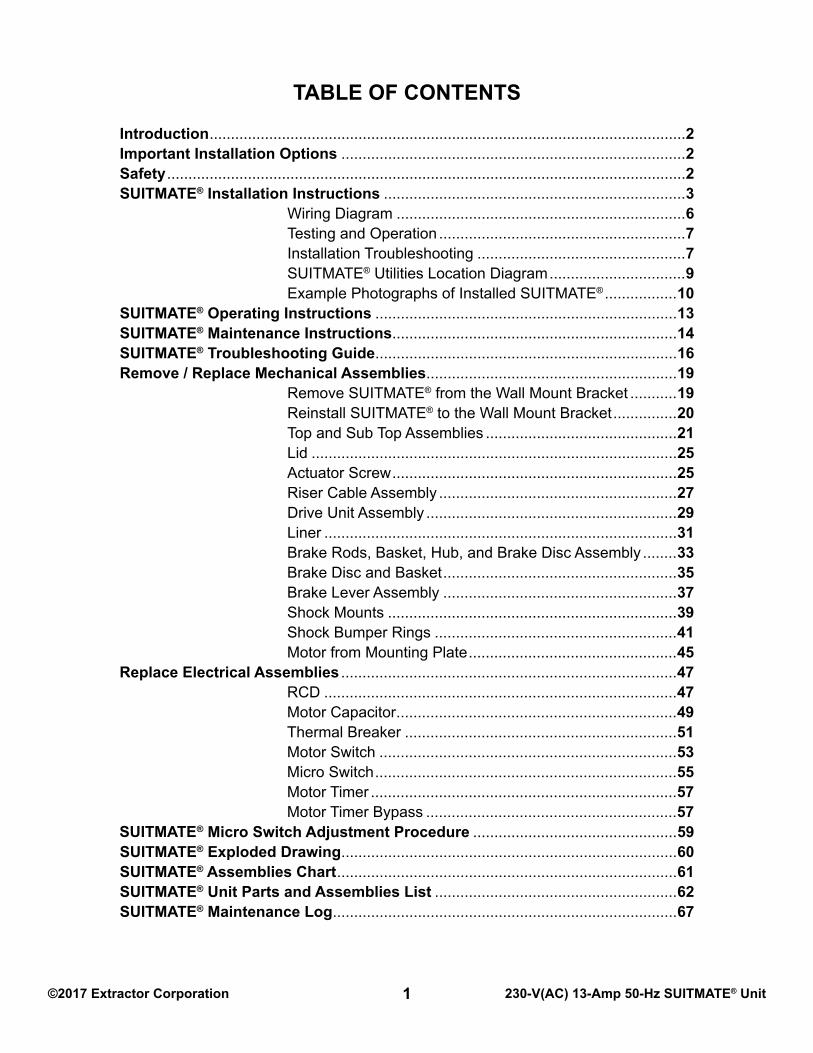
REMOvE SUB-TOP ASSEMBLY1) Remove the Nut from the Turnbuckle that is attached to the Riser Cable. Set the Nut aside for reassembly.2) Pull the Riser Cable with Turnbuckle down through the hole in the Riser Shuttle.3) Remove the (2) rivets from around the outer edge of the Sub-Top and the (1) rivet from the top. a. Punch out the center of each rivet with a small drift punch. b. Drill out each rivet. Note: Make certain the drill bit does not reach a depth of more than ½-inch to avoid damaging the Black Plastic Liner. c. Chisel off the rivet heads. Make certain the rivets are completely removed.4) Separate the Sub-Top from the SUITMATE® unit. Remove the Sub-Top by grasping the sides and lifting straight up.5) Remove rivet debris and any other foreign objects from the Liner.
REPLACE SUB-TOP ASSEMBLY1) Place the SUITMATE® unit in an upright position.2) Locate the (2) Brake Rod holes in the Sub-Top gasket and align them with the Brake Rods. 3) Push the Sub-Top down over the Brake Rods.4) Push the Riser Cable Turnbuckle up and through the hole in the Riser Shuttle.5) Reattach the Nut (removed in step 1 above) to the Turnbuckle that is attached to the Riser Cable.6) Align the (3) holes in the Sub-Top (one on each side and one on the top) with the respective holes in the Case. Note: Make sure that the lip of the Sub-Top is on the outside of the Case.7) Fasten the Sub-Top to the case with (3) Aluminum Pop Rivets.
REPLACE TOP ASSEMBLY1) Place the SUITMATE® unit in an upright position.2) Lift the Lid on the Top Assembly and locate the (2) Brake Rod holes in the Top and align them with the Brake Rods. Push the Top down over the Brake Rods.3) Align the (6) holes in the outer edge of the Top with the corresponding (6) holes in the Case.4) Fasten the Top to the Case with (6) Black Aluminum Pop Rivets.5) Replace the (2) Black Rubber Brake Tips. Note: Check the Micro Switch alignment by following the MICRO SWITCH ADJUSTMENT PROCEDURE section (Page 59) in this manual.6) Reattach the SUITMATE® unit to the Wall Mount Bracket. See instructions beginning on Page 20.7) Retest the SUITMATE® unit for proper operation, refer to TESTING AND OPERATION on page 7.

©2017 Extractor Corporation 230-V(AC) 13-Amp 50-Hz SUITMATE® Unit24
LID (1) CEC1402
(4) AEC1410S.S. POP RIVET
ACORN NUT (1) AEC1803
HINGE PIN, LEFT (1) BEC1403
(1) AEC1405S.S. ACTUATOR SCREW
BLACK O-RING (2) AEC1416
(1) AEC1704S.S. LOCKWASHER
(1) BEC1404HINGE PIN, RIGHT
AEC 1205 (6)BLACK ALUMINUM RIVET
AEC1235 - TIMED UNITINSTRUCTIONS (1)
LID OPERATING
TOP ASSEMBLY (1) EC2
AEC1234LABEL (1)LIFT LID
(1) AEC1404S.S. ACTUATOR SCREW SLEEVE

©2017 Extractor Corporation 230-V(AC) 13-Amp 50-Hz SUITMATE® Unit25
REMOvE LID FROM BLACk PLASTIC TOPDo This FIRSTMake certain you have all the correct parts and fasteners necessary for correct installation. Re-use any components that are not damaged, otherwise replace them. Parts used in this process: (2) AEC1410 S.S. Pop Rivets, (2) AEC1416 Black O-Rings, (1) AEC1704 S.S. Lock Washer, (1) BEC1403 Hinge Pin, Left, (1) AEC1405 Actuator Screw, (1) AEC1404 S. S. Actuator Sleeve, (1) BEC1404 Hinge Pin, Right, and (1) AEC 1803 Acorn Nut. Plus any components required to reinstall the Sub Top and Top Assemblies (Page 23).
REMOvE LID1) Remove SUITMATE® unit from the Wall Mount Bracket. See instructions beginning on Page 19.2) Remove Top and Sub-Top Assemblies. See instructions beginning on Page 21.3) Place the Top Assembly upside down.4) Remove the Acorn Nut, Lock Washer, and Actuator Sleeve from the Actuator Screw.5) Unscrew the Actuator Screw from the Left Hinge Pin.6) Remove the (2) rivets from the outer edge of the S.S. Lid that hold the Left Hinge Pin. a. Punch out the center of each rivet with a small drift pin. b. Drill out each rivet. c. Chisel off the rivet heads. Make certain the rivets are completely removed.7) Remove the hinge pin through the metal Lid. Set the Left Hinge Pin aside for reassembly later.8) Remove the Lid from the Top Assembly. Note: A rubber O-ring is located on each hinge between the metal Lid and the plastic Top.
REPLACE LID1) Insert the Right Hinge Pin into the Top and then insert the Left Hinge Pin through the Lid and into the Top. Note: Make certain that you have reinstalled the Rubber O-Ring on both hinge pins.2) Rivet the Left Hinge Pin to the Lid. Note: be certain the Hinge Pin is flush against the inside of the lid prior to riveting.3) Screw in the new Actuator Screw, re-install Actuator Sleeve, and fasten with Lock Washer and Acorn Nut. (See illustration below)
Note: Make certain that with the lid open, the Actuator Screw does not touch the inside of the black Plastic Top.4) Reinstall the Sub-Top and Top assemblies. See instructions beginning on Page 23.5) Reattach the SUITMATE® unit to the Wall Mount Bracket. See instructions beginning on Page 20.6) Retest the SUITMATE® unit for proper operation, refer to TESTING AND OPERATION on page 7.
ACORN NUT (1) AEC1803
HINGE PIN, LEFT (1) BEC1403
(1) AEC1405S.S. ACTUATOR SCREW
(1) AEC1704S.S. LOCKWASHER
(1) AEC1404S.S. ACTUATOR SCREW SLEEVE

©2017 Extractor Corporation 230-V(AC) 13-Amp 50-Hz SUITMATE® Unit26
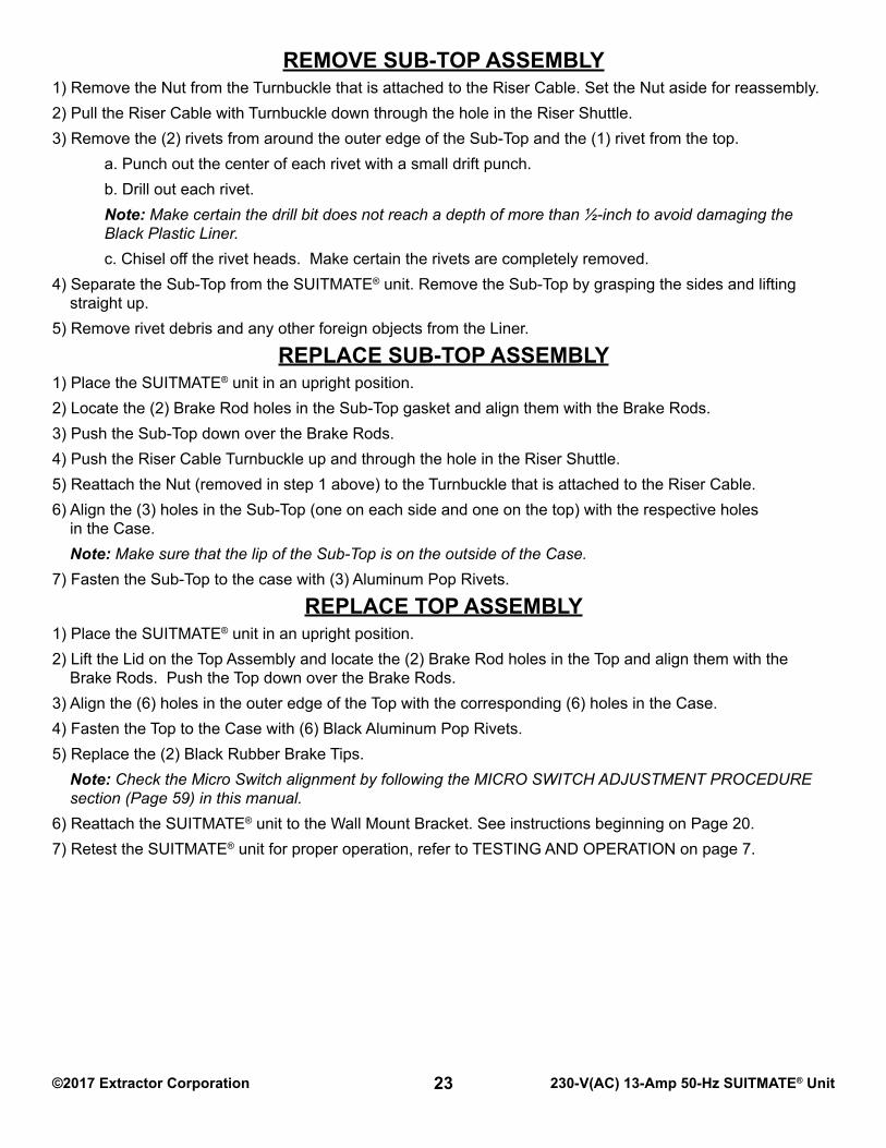
AEC2007RCD JUNCTION BOX
AEC1155CABLE GLAND
(1) AEC1810MICRO SWITCH
NUT (1) AEC1807TURNBUCKLE
MICRO SWITCH BOX (1) BEC1207
RISER CABLE
TURNBUCKLE
AEC1818 GREEN/YELLOW GROUND WIRESECURED TO THIS STUD USING (1) AEC1808STAR LOCK WASHER AND (1) AEC1804 NUT
SCREW (2)AEC1831
MACHINE
NUT (1) AEC1807TURNBUCKLE
BOX (1) BEC1207MICRO SWITCH
MICRO SWITCHBOX COVER(1) AEC1245
(1) AEC1304RISER SHUTTLE
TURNBUCKLE
SOLD AS EC8RISER CABLE ASSEMBLY
RISER SHUTTLE
(1) AEC1417NUT (1) AEC1314 E-RING
AEC1419 (1) TIMER*
RISER CABLE
*Appearance of timer may vary
OFFSET CONNECTOR(1) AEC1212
3 4
1 222

©2017 Extractor Corporation 230-V(AC) 13-Amp 50-Hz SUITMATE® Unit27
REMOvE RISER CABLE ASSEMBLYDo this FIRSTMake certain you have all the correct parts and fasteners necessary for correct installation. Re-use any components that are not damaged, otherwise replace them. Parts used in this process: (2) AEC1807 Turnbuckle Nut, (1) EC8 Riser Cable Assembly, (2) AEC1831 Machine Screw, (1) AEC1245 Micro Switch Box Cover. Plus any components required to reinstall the Sub-Top and Top Assemblies (Page 23).
REMOvE RISER CABLE ASSEMBLY1) Remove SUITMATE® unit from the Wall Mount Bracket. See instructions beginning on Page 19.2) Remove Top and Sub-Top Assemblies. See instructions beginning on Page 21.3) Place the SUITMATE® unit in an upright position with the back of the unit facing out.4) Remove the Micro Switch Box Cover. The cover is held on with (2) Machine Screws. Remove the cover and screws and set aside for reassembly.5) Remove the Turnbuckle Nut from the Turnbuckle.6) Pull the Turnbuckle up and out of the hole in the Micro Switch arm.7) Remove the Riser Cable by pulling it up through the conduit connector at the top of the unit.
REPLACE RISER CABLE ASSEMBLY1) Ensure that all rivet debris and all foreign objects have been removed from the Liner.2) Reinstall Sub-Top Assembly (Page 23) before starting with the Riser Cable replacement.3) Drop the new Riser Cable (with Turnbuckle) down through the conduit to the Micro Switch.4) Insert the Turnbuckle through the hole in the Micro Switch arm. Replace the Nut (saved from step 5 above) on the Turnbuckle.5) Insert the Turnbuckle on the new Riser Cable through the hole in the Riser Shuttle. Replace the Turnbuckle Nut.6) Replace Top Assembly. See instructions beginning on Page 23.7) Push the Lid down. The Micro Switch should NOT activate (click) until the Lid is approximately ¼-inch from being totally depressed. Adjust the alignment by tightening (clockwise – will activate unit sooner) or loosening (counter-clockwise – will activate unit later) the Turnbuckle Nut on the bottom of the Riser Cable until the proper adjustment is obtained. Do not bend the Micro Switch arm. For additional information refer to the MICRO SWITCH ADJUSTMENT PROCEDURE (on Page 59) section in this manual.8) Provide power to the unit to make certain it is functioning properly, test it.9) Disconnect power to the unit.10) Replace the Micro Switch Box Cover securing it with the (2) Machine Screws removed in step 4 above.11) Reattach the SUITMATE® unit to the Wall Mount Bracket. See instructions beginning on Page 20.12) Retest the SUITMATE® unit for proper operation, refer to TESTING AND OPERATION on Page 7.

©2017 Extractor Corporation 230-V(AC) 13-Amp 50-Hz SUITMATE® Unit28
BOTTOM VIEW OF DRIVE UNIT
DRIVE UNIT ASSEMBLY (1) EC23
THIS SHOCK BUMPER RING IN POSITION.SPACER. IT IS REQUIRED TO KEEPNOTE LOCATION OF ALUMINUM
CASE ASSEMBLY (1) EC12
FRONT FACE OF UNIT
AND (3) LOCK WASHERS (AEC1238)CONSISTING OF (3) NUTS (AEC1224)DRIVE UNIT ASSEMBLY MOUNTING
DRIVE UNITREMOVAL OF
SHOCK MOUNT
SUITMATE® UNITBOTTOM VIEW OF
Photograph shows the Correct Position of Wires for Rewiring the Motor
L1 L2
Green/Yellow Wiresecured to MotorFrame with Green(Hex Head) Screwand Lock Washer
Black Wire terminatedwith InsulatedConnector. Secured tothis terminal (L1).
The black clip mustbe installed with thewhite arrow pointingat 230V.
(1) White Wire terminatedwith Insulated Connector.Secured to this terminal (L2).
900 Connector
RCD

©2017 Extractor Corporation 230-V(AC) 13-Amp 50-Hz SUITMATE® Unit29
REMOvE DRIvE UNIT ASSEMBLY FROM CASEDo this FIRSTMake certain you have all the correct parts and fasteners necessary for correct installation. Re-use any components that are not damaged, otherwise replace them. Parts used in this process: (3) AEC1224 Hex Nuts, (3) AEC1238 Lock Washers, (1) AEC1819 Flange Fork Connector, (2) AEC1830 Insulated Connectors, (1) AEC1813 White Wire, (1) AEC1842 Black Wire, and (1) AEC1813 Green / Yellow Wire. Plus any components required to correctly reinstall the Sub-Top and Top Assemblies (Page 23).
REMOvE DRIvE UNIT ASSEMBLY1) Remove SUITMATE® unit from the Wall Mount Bracket. See instructions beginning on Page 19.2) Remove Top and Sub-Top Assemblies. See instructions beginning on Page 21.3) Place the SUITMATE® on its face to expose the bottom of the unit.4) Unscrew the (2) captive screws that secure the Motor end cap from the bottom of the Motor.5) Remove the end cap with captive screws and set it aside for reassembly.6) Remove the Micro Switch Box Cover. The cover is held on with (2) Machine Screws. Remove cover and screws and set aside for reassembly.7. Disconnect the (3) wires connecting the motor to the unit by disconnecting the wires from the L1 and L2 terminals on the Motor. Loosen the Green Grounding screw and disconnect the green/yellow ground wire.8) Cut off the (3) wire connectors from the wires to allow the wires to be pulled through the 90o conduit connector.9) Pull the wires through the 90o conduit connector by pulling them from the Micro Switch Box about 2 to 3 inches.10) Remove the 90o conduit connector from the Motor by disconnecting the plastic cable conduit from the 90o conduit connector and unscrewing the 90o conduit connector from the Motor.11) Return the SUITMATE® unit to its upright position.12) Remove the three sets of Hex Nuts and Lock Washers that hold the Drive Unit to the Case. Set them aside for reassembly.13) From the top of the SUITMATE® unit, grasp the sides of the Basket. Remove the Drive Unit by lifting the Drive Unit up at a slight angle. Note: Be careful not to damage the Black Plastic Liner. If the Liner is damaged, it must be replaced.
REPLACE DRIvE UNIT ASSEMBLY1) Align the (3) Shock Mounts on the Drive Unit with the (3) holes in the Case and lower the Drive Unit into the Case making certain that the (3) Shock Mounts are in the appropriate holes in the Case, so that the 90o connector will be in the correct position. See the Bottom View diagram of the SUITMATE® unit on Page 28. Note: Be careful not to damage the Black Plastic Liner. If the Liner is damaged, it must be replaced.2) Replace the (3) sets of Hex Nuts and Lock Washers on the Shock Mount threaded inserts that protrude through the Case.3) Replace the 90o conduit connector by screwing it into the Motor. Note: Be careful not to cross thread the threads on the 90o conduit connector.4) Reconnect the plastic cable conduit to the 90o conduit connector.5) Push the (3) wires from the Micro Switch Box up into the Motor.6) Strip the (3) wires enough to install the NEW appropriate wire connectors on the wires.7) Reattach the (3) wire connectors to the appropriate terminals in the Motor: Green / Yellow Wire to green screw, (1) White Wire to terminal L2, and Black Wire to terminal L1.8) Reinstall the Motor end cap with the (2) captive screws removed in step 5 above.9) Reinstall the Sub-Top and Top Assemblies. See instructions beginning on Page 23.10) Reattach the SUITMATE® unit to the Wall Mount Bracket. See instructions beginning on Page 20.11) Retest the SUITMATE® unit for proper operation, refer to TESTING AND OPERATION on Page 7.

©2017 Extractor Corporation 230-V(AC) 13-Amp 50-Hz SUITMATE® Unit30
BLACK DRAIN HOSE(1) AEC1248
S.S. HOSE CLAMP(1) AEC1249
FOAM STRIP(4) AEC1244
BLACK PLASTIC LINER(1) DEC1213
CASE(1) DEC1201
FOAM STRIP(1) AEC1243

©2017 Extractor Corporation 230-V(AC) 13-Amp 50-Hz SUITMATE® Unit31
REMOvE / REPLACE BLACk PLASTIC LINER FROM CASEDo this FIRSTMake certain you have all the correct parts and fasteners necessary for correct installation. Re-use any components that are not damaged, otherwise replace them. Parts used in this process: (4) AEC1244 Foam Strips, (1) DEC1213 Black Plastic Liner, (1) AEC1249 S.S. Hose Clamp, (1) AEC1248 Black Drain Hose, and (1) AEC1243 Foam Strip. Plus any components required to properly reinstall the Drive Unit Assembly (Page 29) and the Sub-Top and Top Assemblies (Page 23).
REMOvE LINER 1) Remove SUITMATE® unit from the Wall Mount Bracket. See instructions beginning on Page 19.2) Remove Top and Sub-Top Assemblies. See instructions beginning on Page 21.3) Remove Drive Unit Assembly. See instructions beginning on Page 29.4) Place the SUITMATE® unit on its face to expose the bottom of the unit.5) If the factory supplied drain hose was used, unscrew the hose clamp that holds the plastic drain tube to the Liner drain hose outlet.6) Remove the drain hose and set it aside for reassembly.7) Place the SUITMATE® unit in an upright position.8) From the top of the SUITMATE® unit, grasp the lip of the Black Plastic Liner and pull straight up. Be careful not to damage the Liner. If the Liner is damaged, it must be replaced.
REPLACE LINER1) Place the Liner into the case using care not to damage it.2) If the factory supplied drain hose was used, reinstall it using the hose clamp removed in step 5 above.3) Reinstall the Drive Unit. See instructions beginning on Page 29.4) Reinstall the Sub-Top and Top Assemblies. See instruction beginning on Page 23.5) Reattach SUITMATE® unit to the Wall Mount Bracket. See instructions beginning on Page 20.6) Retest the SUITMATE® unit proper operation, refer to TESTING AND OPERATION on Page 7.

©2017 Extractor Corporation 230-V(AC) 13-Amp 50-Hz SUITMATE® Unit32
SHORT
SPRING (2) AEC1622COMPRESSION
S.S. THREADED BRAKEROD (2) AEC1620
BRAKE LEVER ARMSMOUNTING PLATE WITH
MOTOR (1) BEC2001
S.S. LOCKNUT (2) AEC1624
(1) EC18
BASKET, HUB, AND
(1) AEC1506HUB ROLL PIN
(1) EC22DISC ASSEMBLY

©2017 Extractor Corporation 230-V(AC) 13-Amp 50-Hz SUITMATE® Unit33
REMOvE AND REPLACE BRAkE RODS, BASkET, HUB, AND BRAkE DISC ASSEMBLY Do this FIRST Make certain you have all the correct parts and fasteners necessary for correct installation. Re-use any components that are not damaged, otherwise replace them. Parts used in this process: (1) EC22 Basket and Brake Disc Assembly, (1) AEC1506 Hub Roll Pin, (2) AEC1620 S.S. Threaded Brake Rods, (2) AEC1622 Short Compression Springs, (2) AEC1624 S.S. Locknuts, and (1) BEC2001 Motor, 230 V 50 Hz. Plus any components required to properly reinstall the Drive Unit Assembly (Page 29) and the Sub-Top and Top Assemblies (Page 23).
REMOvE BRAkE RODS, BASkET, HUB, AND BRAkE DISC ASSEMBLY 1) Remove SUITMATE® unit from the Wall Mount Bracket. See instructions beginning on Page 19.2) Remove Top and Sub-Top Assemblies. See instructions beginning on Page 21.3) Remove Drive Unit Assembly. See instructions beginning on Page 29. Note: If Basket itself is damaged it must be replaced, please contact Extractor Corporation at: (Telephone) 1-847-742-3532, (Fax) 1-847-742-3552, or (Email) [email protected]) Remove the Brake Rods from the Drive Unit Assembly by removing the Locknut and Short Compression Spring on each Brake Rod. Set the Brake Rods, springs, and locknuts aside for reassembly. Inspect and replace the Short Compression Springs if any wear or deformation is observed.5) Place a C-clamp over each Brake Lever Arm and under the Motor Mounting Plate. Tighten the C-clamps to allow free rotation of the Basket and Motor shaft. Note: Do not remove C-clamps!6) Rotate the Hub so that the hole for the Hub Roll Pin that holds the Basket, Hub and Brake Disc Assembly to the Motor shaft can be clearly seen.7) Use a hammer and a 3/16” drift punch to remove the Hub Roll Pin that holds the Basket, Hub and Brake Disc Assembly to the Motor shaft. A new Hub Roll Pin is required for reassembly (Part Number AEC1506).8) Using a small pry bar or large screwdriver, pry up on the Hub to free it from the Motor shaft. Rotate the Hub so that even pressure is exerted evenly around the Hub and Motor shaft. Repeat until you can manually remove the Basket, Hub and Brake Disc Assembly from the Motor shaft. Be careful not to damage the Hub or the Motor Mounting Plate. If the Hub is “frozen” to the Motor shaft, please contact Extractor Corporation at: (Telephone) 1-847-742-3532, (Fax) 1-847-742-3552, or (Email) [email protected] and explain your problem.
REPLACE BRAkE RODS, BASkET, HUB, AND BRAkE DISC ASSEMBLY1) Push the Basket, Hub, and Brake Disc Assembly onto the Motor Shaft so that the hole in the Hub lines up with the hole in the Motor Shaft. Note: Apply a light coat of grease to the Motor Shaft to facilitate assembly. Note: It may be necessary to gently tap the Hub down onto the Motor shaft. Do not tap or pound directly on the basket.2) Use a 3/16” drive pin punch to test for the proper hole alignment of the Hub and the Motor Shaft.3) Drive a NEW Hub Roll Pin (Part Number AEC1506) into the Hub and through the Motor Shaft so that the pin is flush with the Hub.4) Remove the C-clamps.5) Reinstall the Brake Rods onto the Drive Unit Assembly by installing the locknut and spring on each Brake Rod removed in step 4 above.6) Reinstall Drive Unit Assembly. See instructions beginning on Page 29.7) Reinstall Sub-Top and Top Assemblies. See instructions beginning on Page 23.8) Reattach SUITMATE® unit to the Wall Mount Bracket. See instructions beginning on Page 20.9) Retest the SUITMATE® unit for proper operation, refer to TESTING AND OPERATION on Page 7.

©2017 Extractor Corporation 230-V(AC) 13-Amp 50-Hz SUITMATE® Unit34
BASKET ANDHUB ASSEMBLY (1) EC20
HUB
S.S. SCREW (3) AEC1703
S.S. LOCKWASHER(3) AEC1704
(1) BEC1702S.S. BRAKE DISC

©2017 Extractor Corporation 230-V(AC) 13-Amp 50-Hz SUITMATE® Unit35
REMOvE / REPLACE BRAkE DISC AND BASkETDo this FIRSTMake certain you have the correct parts and fasteners necessary for correct installation. Re-use any components that are not damaged, otherwise replace them. Parts used in this process: (1) EC20 Basket and Hub Assembly, (1) BEC1702 S.S. Brake Disc, (3) AEC1704 S.S. Lock washers, (3) AEC1703 S.S. Screws. Plus any components required to properly reinstall the Drive Unit Assembly (Page 29) and the Sub-Top and Top Assemblies (Page 23).
REMOvE BRAkE DISC AND BASkET1) Remove SUITMATE® unit from the Wall Mount Bracket. See instructions beginning on Page 19.2) Remove Top and Sub-Top Assemblies. See instructions beginning on Page 21.3) Remove Drive Unit Assembly. See instructions beginning on Page 29.4) Remove Brake Rods, Basket, Hub and Brake Disc Assembly. See instructions beginning on Page 33.5) Remove the (3) S.S. Screws and Lock Washers from the bottom of the Hub Assembly. Set them aside for reassembly.6) Remove the Brake Disc from the Hub. The Brake Disc may have to be tapped off using a small plastic hammer. Replace if necessary.
REPLACE BRAkE DISC AND BASkET1) Replace the Brake Disc by assembling it over the Hub and aligning the (3) holes. Secure the Brake Disc using the (3) S.S. Screws and (3) Lock Washers removed in step 5 above. Note: Apply a light coat of grease to the screws to facilitate assembly.2) Reinstall the Brake Disc and Basket Assembly onto the motor shaft. See instructions beginning on Page 33.3) Reinstall the Brake Rods to the Drive Unit Assembly by installing the Locknut and Short Compression Spring on each Brake Rod. See instructions beginning on Page 33.4) Reinstall Drive Unit Assembly. See instructions beginning on Page 29.5) Reinstall Sub-Top and Top Assemblies. See instructions beginning on Page 23.6) Reattach SUITMATE® unit to the Wall Mount Bracket. See instructions beginning on Page 20.7) Retest the SUITMATE® unit for proper operation, refer to TESTING AND OPERATION on Page 7.

©2017 Extractor Corporation 230-V(AC) 13-Amp 50-Hz SUITMATE® Unit36
S.S. LONG COMPRESSION
PIN (1) AEC1614 BRAKE HINGE
WHITE PLASTIC
SPRING (2) AEC1612
WHITE PLASTIC BUSHING
PLATE ASSEMBLY (1) EC17MOTOR MOUNTING
(2) AEC1609FLAT WASHER
BRAKE LEVER ASSEMBLY (2) EC16
(2) AEC1603
BRACKET
(1) AEC1823S.S. POP RIVET
(1) AEC1601
BUSHING(2) AEC1603
ASSEMBLY (1) EC16
BRAKE SUPPORT
BRAKE LEVER
(2) AEC1827NYLON WASHER
MOTOR MOUNTING PLATE

©2017 Extractor Corporation 230-V(AC) 13-Amp 50-Hz SUITMATE® Unit37
REMOvE / REPLACE BRAkE LEvER ASSEMBLYDo this FIRSTMake certain you have all the correct parts and fasteners necessary for correct installation. Re-use any components that are not damaged, otherwise replace them. Extractor recommends that a Brake Parts Kit AEC2300 be purchased. In the absence of purchasing a Brake Parts Kit, the following parts are used in this process: (2) AEC1614 Brake Hinge Pins, (6) AEC1603 White Plastic Bushings, (4) AEC1827 Nylon Washers, (2) EC16 Brake Lever Assemblies, (2) AEC1601 Brake Support Brackets, (2) AEC1823 S.S. Pop Rivets. Plus any components required to properly reinstall the Basket and Brake Disc Assembly (Page 35), the Drive Unit Assembly (Page 29), and the Sub-Top and Top Assemblies (Page 23).
REMOvE BRAkE LEvER ASSEMBLY1) Remove SUITMATE® unit from the Wall Mount Bracket. See instructions beginning on Page 19.2) Remove Top and Sub-Top Assemblies. See instructions beginning on Page 21.3) Remove Drive Unit Assembly. See instructions beginning on Page 29.4) Remove Basket, Hub, and Brake Disc Assembly. See instructions beginning on Page 33. Note: Make certain that the C-clamps have been removed from the brake levers.5) Remove the Long Compression Spring, Flat Washer, and White Plastic Bushing. Set them aside for reassembly. Note: Pay attention to the location of the spring, washer and plastic bushing. It is recommended that the compression spring be replaced with a new Long Compression Spring (AEC1612).6) Remove the rivet that holds the Brake Lever Assembly to the Brake Support Bracket on the Motor Mounting Plate. Refer to drawing on bottom of Page 36. a. Punch out the center of each rivet with a small drift punch. b. Drill out the rivet. c. Chisel off the rivet head.7) Remove and discard the Brake Hinge Pin.8) Remove the old Brake Lever Assembly. Note: Pay attention to the placement and alignment of the plastic bushings and plastic washers in the Brake Assembly. Set them aside for reassembly. Inspect the Brake levers, springs and plastic bushings and washers for wear and replace with new ones if necessary.
REPLACE BRAkE LEvER ASSEMBLY1) Replace the Brake Lever Assembly by reversing the above procedure. A NEW Hinge Pin and pop rivet MUST be used. Note: Be certain that the plastic bushing and washers are in “new” condition and in their proper locations. Make certain to reinstall the C-clamps on the brake levers. The height of the brake Pad should be less than 1 3/8 inches (3.5cm) high as measured from the Motor Mounting Plate.2) Reinstall the Brake Disc and Basket. See instructions beginning on Page 35.3) Reinstall Drive Unit Assembly. See instructions beginning on Page 29.4) Reinstall Sub-Top and Top Assemblies. See instructions beginning on Page 23.5) Reattach SUITMATE® unit to the Wall Mount Bracket. See instructions beginning on Page 20.6) Retest the SUITMATE® unit for proper operation, refer to TESTING AND OPERATION on Page 7.

©2017 Extractor Corporation 230-V(AC) 13-Amp 50-Hz SUITMATE® Unit38
SHOCK BUMPER
BOTTOM VIEW OF DRIVE UNIT
REAR OF SUITMATE® UNIT
OF THE ALUMINUM SPACER (AEC1822)RING MUST BE ALIGNED AGAINST THE ENDNOTE: THE SIDE OF THE SHOCK BUMPER
TO DRIVE UNITCONNECTOR
POSITION OFELECTRICAL
AEC1202
HEX NUT (3)
MOUNT (3)SHOCK
AEC1224
RING (3) AEC1223
FROM PULLING
WASHER INSIDE
AEC1206
THROUGH (3)
STOP RIVETBUMPER TO
AEC1228
S.S. POP RIVET (3)

©2017 Extractor Corporation 230-V(AC) 13-Amp 50-Hz SUITMATE® Unit39
REMOvE AND REPLACE SHOCk MOUNTSDo this FIRSTMake certain you have all the correct parts and fasteners necessary for correct installation. Re-use any components that are not damaged, otherwise replace them. Parts used in this process: (3) AEC1202 Shock Mounts, (3) AEC1224 S.S. Hex Nuts. Plus any components required to properly reinstall the Drive Unit Assembly (Page 29) and the Sub-Top and Top Assemblies (Page 23).
REMOvE SHOCk MOUNTS1) Remove SUITMATE® unit from the Wall Mount Bracket. See instructions beginning on Page 19.2) Remove Top and Sub-Top Assemblies. See instructions beginning on Page 21.3) Remove Drive Unit Assembly. See instructions beginning on Page 29.4) Remove the S.S. Hex Nut that secures the Shock Mount to the Shock Bumper Ring.5) Remove the Shock Mount from the Shock Bumper Ring.
REPLACE SHOCk MOUNTS1) Install the new Shock Mount to the Shock Bumper Ring and secure using the S.S. Hex Nut. Note: Use a small drop of threadlocker when securing the S.S. Hex Nut. Note: Use new S.S. Hex Nuts if necessary.2) Reinstall Drive Unit Assembly. See instructions beginning on Page 29.3) Reinstall Sub-Top and Top Assemblies. See instructions beginning on Page 23.4) Reattach SUITMATE® unit to the Wall Mount Bracket. See instructions beginning on Page 20.5) Retest the SUITMATE® unit for proper operation, refer to TESTING AND OPERATION on Page 7.

©2017 Extractor Corporation 230-V(AC) 13-Amp 50-Hz SUITMATE® Unit40
SHOCK BUMPER
BOTTOM VIEW OF DRIVE UNIT
REAR OF SUITMATE® UNIT
OF THE ALUMINUM SPACER (AEC1822)RING MUST BE ALIGNED AGAINST THE ENDNOTE: THE SIDE OF THE SHOCK BUMPER
TO DRIVE UNITCONNECTOR
POSITION OFELECTRICAL
AEC1202
HEX NUT (3)
MOUNT (3)SHOCK
AEC1224
RING (3) AEC1223
FROM PULLING
WASHER INSIDE
AEC1206
THROUGH (3)
STOP RIVETBUMPER TO
AEC1228
S.S. POP RIVET (3)

©2017 Extractor Corporation 230-V(AC) 13-Amp 50-Hz SUITMATE® Unit41
REMOvE AND REPLACE SHOCk BUMPER RINGSDo this FIRSTMake certain you have all the correct parts and fasteners necessary for correct installation. Re-use any components that are not damaged, otherwise replace them. Parts used in this process: (3) AEC1223 Shock Bumper Rings, (3) AEC1228 Washers, (3) AEC1206 S.S. Pop Rivets. Plus any components required to properly reinstall the Shock Mounts (Page 41), the Basket, Hub and Brake Disc Assembly (Page 33), the Drive Unit Assembly (Page 29), and the Sub-Top and Top Assemblies (Page 23).
REMOvE SHOCk BUMPER RINGS1) Remove SUITMATE® unit from the Wall Mount Bracket. See instructions beginning on Page 19.2) Remove Top and Sub-Top Assemblies. See instructions beginning on Page 21.3) Remove Drive Unit Assembly. See instructions beginning on Page 29.4) Remove the (3) S.S. Hex Nuts that secure the (3) Shock Mounts to the (3) Shock Bumper Rings.5) Remove each Shock Mount from each Shock Bumper Ring. Note: Examine the positions of the 3 Shock Bumper Rings. Two Bumper Rings should be parallel to each other. The third should be perpendicular to the other two. See Bottom View of Drive unit on Page 40 for details.6) Remove the rivet that holds the Shock Bumper Ring to the Motor Mounting Plate. a. Punch out center of the rivet with a small drift punch. b. Drill out the rivet. c. Chisel off the rivet head. Make sure the rivet is completely removed. Note: Set aside the small washer that helps to secure the Shock bumper Ring to the Motor Mounting Plate. If the washers are deformed, they must be replaced.
REPLACE SHOCk BUMPER RINGS1) Rivet the Shock Bumper Ring to the Motor Mounting Plate. Note: be certain to use the small washer (AEC1228) in riveting the Shock bumper Ring to the Motor Mounting Plate. Make certain the Shock bumper Ring Assembly is properly aligned with the other two bumper Rings. Failure to do so will prevent proper reassembly of the SUITMATE® unit.2) Apply clear Silicone sealer (available locally) on the rivet head located on top of the Motor Mounting Plate.3) Reinstall the (3) Shock Mounts. See instructions beginning on page 39.4) Reinstall Drive Unit Assembly. See instructions beginning on Page 29.5) Reinstall Sub-Top and Top Assemblies. See instructions beginning on Page 23.6) Reattach the SUITMATE® unit to the Wall Mount Bracket. See instructions beginning on Page 20.7) Retest the SUITMATE® unit for proper operation, refer to TESTING AND OPERATION on Page 7.

©2017 Extractor Corporation 230-V(AC) 13-Amp 50-Hz SUITMATE® Unit42
BOTTOM VIEW OF DRIVE UNIT
DRIVE UNIT ASSEMBLY (1) EC23
THIS SHOCK BUMPER RING IN POSITION.SPACER. IT IS REQUIRED TO KEEPNOTE LOCATION OF ALUMINUM
CASE ASSEMBLY (1) EC12
FRONT FACE OF UNIT
AND (3) LOCK WASHERS (AEC1238)CONSISTING OF (3) NUTS (AEC1224)DRIVE UNIT ASSEMBLY MOUNTING
DRIVE UNITREMOVAL OF
SHOCK MOUNT
SUITMATE® UNITBOTTOM VIEW OF
Photograph shows the Correct Position of Wires for Rewiring the Motor
L1 L2
Green/Yellow Wiresecured to MotorFrame with Green(Hex Head) Screwand Lock Washer
Black Wire terminatedwith InsulatedConnector. Secured tothis terminal (L1).
The black clip mustbe installed with thewhite arrow pointingat 230V.
(1) White Wire terminatedwith Insulated Connector.Secured to this terminal (L2).
900 Connector
RCD

©2017 Extractor Corporation 230-V(AC) 13-Amp 50-Hz SUITMATE® Unit43
ALUMINUM SPACER (1) AEC1822: NOTELOCATION OF THIS SPACER ASREINSTALLATION AT PROPER LOCATION IS AREQUIREMENT. THE SIDE OF THE SHOCKBUMPER MUST BE ALIGNED AGAINST THEEND OF THE ALUMINUM SPACER.
MOUNTING PLATE/BRAKE LEVERSASSEMBLY EC18
MOTOR (1)BEC2001
MOTOR MOUNT SPACER(3) AEC1504
LOCK WASHER (4) AEC1203HEX HEAD BOLT (4) AEC1505

©2017 Extractor Corporation 230-V(AC) 13-Amp 50-Hz SUITMATE® Unit44
Position of 90° Electricalconnector to drive unit
Location ofAEC1822AluminumSpacer

©2017 Extractor Corporation 230-V(AC) 13-Amp 50-Hz SUITMATE® Unit45
REMOvE AND REPLACE MOTORDo this FIRSTMake certain you have all the correct parts and fasteners necessary for correct installation. Re-use any parts that are not damaged, otherwise replace them. Parts used in this process: (1) AEC1822 Aluminum Spacer, (3) AEC1504 Motor Mount Spacers, (4) AEC1505 Hex Head Bolts, (4) AEC1203 Lock Washers, and (1) BEC2001 Motor 230-V(AC) 50-Hz. Plus any components required to properly reinstall the Basket, Hub, and Brake Disc Assembly (Page 33), the Drive Unit Assembly (Page 29), and the Sub-Top and Top Assemblies (Page 23).
REMOvE MOTOR FROM MOUNTING PLATE1) Remove SUITMATE® unit from the Wall Mount Bracket. See instructions beginning on Page 19.2) Remove Top and Sub-Top Assemblies. See instructions beginning on Page 21.3) Remove Drive Unit Assembly. See instructions beginning on Page 29.4) Remove Basket, Hub, and Brake Disc Assembly. See instructions beginning on Page 33.5) Referring to the photograph and drawings on Page 42 through 44, remove the (4) Hex Head Bolts, Lock Washers, and Motor Mount Spacers that hold the Motor to the Mounting Plate. Note: Examine the placement of the (4) spacers, especially the AEC1822 Aluminum Spacer next to the Shock Bumper Ring. The rectangular spacer prevents the Shock Bumper Ring from moving. Examine the location of the Motor for the 90o connector in relation to the three Shock Mounts. 6) Remove the Motor and set aside.
REPLACE MOTOR1) Replace the motor using the (4) bolts and (4) lock washers, especially noting placement of the AEC1822 Aluminum Spacer next to the Shock Bumper Ring. See Bottom View of Drive Unit on Page 44 for detail. In addition see the photograph and drawings on Pages 42 and 44. Note: When reassembling, use silicone sealer on the bolts and lock washers to preserve water tightness.2) Reinstall Basket, Hub, and Brake Disc Assembly. See instructions beginning on Page 33.3) Reinstall Drive Unit Assembly. See instructions beginning on Page 29.4) Reinstall Sub-Top and Top Assemblies. See instructions beginning on Page 23.5) Reattach the SUITMATE® unit to the Wall Mount Bracket. See instructions beginning on Page 20.6) Retest the SUITMATE® unit for proper operation. Refer to TESTING AND OPERATION on Page 7.
©2017 Extractor Corporation 230-V(AC) 13-Amp 50-Hz SUITMATE® Unit46
BOTTOM VIEW OF SUITMATE® UNITSHOWING LOCATION OF RCD
FASTENERS
RCD Junction Box Coverand (4) Plastic FastenersAEC1155
Cable Gland

©2017 Extractor Corporation 230-V(AC) 13-Amp 50-Hz SUITMATE® Unit47
ELECTRICAL ASSEMBLIES230-V(AC) 13-Amp 50-Hz SUITMATE® Unit
GENERALWhen servicing the SUITMATE® unit, observe the following safety precautions:Always turn off the power at the circuit breaker – place a lockout tag on the circuit breaker panel indicating that the breaker is not to be turned on except by authorized personnel – and disconnect the unit before doing any work on the SUITMATE® unit. Simply turning off a switch is NOT enough.Use only proper tools, test equipment, and work practices when servicing the SUITMATE® unit. If there are any questions concerning proper tools, equipment or practices, please contact the factory for recommendations at: (Telephone) 1-847-742-3532, (Fax) 1-847-742-3552, or (Email) [email protected] to critical tolerances, use only specified replacement parts. See the SUITMATE® UNIT PARTS AND ASSEMBLIES LIST in this manual.
REMOvE AND REPLACE RCDThe RCD can be serviced from the bottom of the unit without removing the unit from the wall.Do This FIRSTMake certain you have all the correct parts and fasteners necessary for correct installation. Parts used in this process: (1) AEC2009 RCD 230-V(AC) 50-Hz.
REMOvE RCD1) Turn off the main electrical power to the unit – place a lockout tag on the circuit breaker panel indicating that the breaker is not to be turned on except by authorized personnel, and disconnect the unit before doing any work on the SUITMATE® unit. Simply turning off a switch in NOT enough.2) Remove the Bottom Plate that is attached with six screws. Save the Bottom Plate and the six mounting screws as they will be required to reinstall the Bottom Plate. Note: If electrical of plumbing connections were routed through the Bottom Plate, it may be necessary to disconnect them prior to removing the Bottom Plate. Refer to External Plumbing and/or Electrical Service connections in this manual. See Page 8 for additional information.3) Remove the cover of the weatherproof Junction Box that contains the RCD. Set the cover and (4) plastic screws aside for reassembly.4) Remove the RCD from the weatherproof Junction Box.
REPLACE RCD1) Remove the wires, one at a time, and put each wire in the matching position on the new RCD (refer to SUITMATE® WIRING DIAGRAM on page 6).2) Place the newly wired RCD into the weatherproof Junction Box and secure it. Terminal connections should be tightened to a torque of 2.3Nm (20 lbf-in) DO NOT connect using power driven screwdrivers.3) Replace the cover of the weatherproof Junction Box using the (4) screws previously removed.4) Replace the Bottom Plate that is attached with six screws. Note: If electrical or plumbing connections were disconnected during the removal of the Bottom Plate, reroute and reconnect them prior to reinstalling the Bottom Plate. Refer to External Plumbing and/or Electrical Service connections in this manual. See Page 8 for additional information.5) Turn on the main electrical power to the unit and retest to assure proper operation. Refer to TESTING AND OPERATION on page 7.

©2017 Extractor Corporation 230-V(AC) 13-Amp 50-Hz SUITMATE® Unit48
MOTOR ENDCAP SCREWS (2)
MOTOR ENDCAP AEC1910
Photograph shows the location of various motor components
MOTOR SWITCH
CAPACITOR
THERMAL BREAKER

©2017 Extractor Corporation 230-V(AC) 13-Amp 50-Hz SUITMATE® Unit49
REMOvE AND REPLACE MOTOR CAPACITOR The Motor Capacitor can be serviced from the bottom of the unit without removing the unit from the wall.Do This FIRSTMake certain you have all the correct parts and fasteners necessary for correct installation. Parts used in this process: (1) AEC1906 Motor Capacitor.
REMOvE MOTOR CAPACITOR1) Turn off the main electrical power to the unit – place a lockout tag on the circuit breaker panel indicating that the breaker is not to be turned on except by authorized personnel and disconnect the unit before doing any work on the SUITMATE® unit. Simply turning off a switch is NOT enough.2) Remove the Bottom Plate that is attached with six screws. Save the Bottom Plate and the six mounting screws as they will be required to reinstall the Bottom Plate. Note: If electrical or plumbing connections were routed through the Bottom Plate, it may be necessary to disconnect them prior to removing the Bottom Plate. Refer to External Plumbing and/or Electrical Service connections in this manual. Refer to Page 8 for additional information.3) Remove the Motor End Cap by loosening the (2) captive screws and setting the end cap aside.4) Remove the screw on the Motor’s post that holds the Capacitor retaining piece and the plastic shield. Set the piece and the shield aside for reassembly. Note: Carefully note the position and location of the old Capacitor as the new Capacitor MUST be installed in the same position and location as the old one. Refer to Page 50 for additional information.
REPLACE MOTOR CAPACITOR1) Remove the wires, one at a time, from the old Capacitor and put each wire in the matching position on the new Capacitor.2) Remove the old Capacitor and position the newly wired Capacitor in the Motor using the previously removed plastic shield and retaining piece. Replace and tighten the screw on the Motor post.3) Replace the previously removed Motor End Cap.4) Replace the Bottom Plate that is attached with six screws. Note: If electrical or plumbing connections were disconnected during the removal of the Bottom Plate, reroute and reconnect them prior to reinstalling the Bottom Plate. Refer to External Plumbing and/or Electrical Service connections in this manual. Refer to Page 8 for additional information.5) Turn on the main electrical power to the unit and retest to assure proper operation. Refer to TESTING AND OPERATION on Page 7.

©2017 Extractor Corporation 230-V(AC) 13-Amp 50-Hz SUITMATE® Unit50
MOTOR ENDCAP SCREWS (2)
MOTOR ENDCAP AEC1910
Photograph shows the location of various motor components
MOTOR SWITCH
CAPACITOR
THERMAL BREAKER

©2017 Extractor Corporation 230-V(AC) 13-Amp 50-Hz SUITMATE® Unit51
REMOvE AND REPLACE THERMAL BREAkER The Thermal Breaker can be serviced from the bottom of the unit without removing the unit from the wallDo This FIRSTMake certain you have all the correct parts and fasteners necessary for correct installation. Parts used in this process: (1) AEC1908 Thermal Breaker.
REMOvE THERMAL BREAkER1) Turn off the main electrical power to the unit – place a lockout tag on the circuit breaker panel indicating that the breaker is not to be turned on except by authorized personnel and disconnect the unit before doing any work on the SUITMATE® unit. Simply turning off a switch is NOT enough.2) Remove the Bottom Plate that is attached with six screws. Save the Bottom Plate and the six mounting screws as they will be required to reinstall the Bottom Plate. Note: If electrical or plumbing connections were routed through the Bottom Plate, it may be necessary to disconnect them prior to removing the Bottom Plate. Refer to External Plumbing and/or Electrical Service connections in this manual. Refer to Page 8 for additional information.3) Remove the Motor End Cap by loosening the (2) captive screws and setting the end cap aside.4) Remove the hex head screw holding the Thermal Breaker in place. Set it aside for reassembly later. Note: Carefully note the position and location of the old Thermal Breaker as the new Thermal Breaker MUST be installed in the same position and location as the old one. Refer to Page 52 for additional information.
REPLACE THERMAL BREAkER1) Remove the wires, one at a time, from the Motor and replace them with the same color wires from the new Thermal Breaker. Note the color and the post which it is attached.2) Replace the old Thermal Breaker with the newly connected Thermal Breaker.3) Position the Thermal Breaker in the Motor and tighten the hex head screw previously removed.4) Replace the previously removed Motor End Cap.5) Replace the Bottom Plate that is attached with six screws. Note: If electrical or plumbing connections were disconnected during the removal of the Bottom Plate, reroute and reconnect them prior to reinstalling the Bottom Plate. Refer to External Plumbing and/or Electrical Service connections in this manual. Refer to Page 8 for additional information.6) Turn on the main electrical power to the unit and retest to assure proper operation. Refer to TESTING AND OPERATION on Page 7.

©2017 Extractor Corporation 230-V(AC) 13-Amp 50-Hz SUITMATE® Unit52
MOTOR ENDCAP SCREWS (2)
MOTOR ENDCAP AEC1910
Photograph shows the location of various motor components
MOTOR SWITCH
CAPACITOR
THERMAL BREAKER

©2017 Extractor Corporation 230-V(AC) 13-Amp 50-Hz SUITMATE® Unit53
REMOvE AND REPLACE MOTOR SWITCHThe Motor Switch can be serviced from the bottom of the unit without removing the unit from the wall.Do This FIRSTMake certain you have all the correct parts and fasteners necessary for correct installation. Parts used in this process: (1) AEC1905 Motor Switch.
REMOvE MOTOR SWITCH1) Turn off the main electrical power to the unit – place a lockout tag on the circuit breaker panel indicating that the breaker is not to be turned on except by authorized personnel and disconnect the unit before doing any work on the SUITMATE® unit. Simply turning off a switch is NOT enough.2) Remove the Bottom Plate that is attached with six screws. Save the Bottom Plate and the six mounting screws as they will be required to reinstall the Bottom Plate. Note: If electrical or plumbing connections were routed through the Bottom Plate, it may be necessary to disconnect them prior to removing the Bottom Plate. Refer to External Plumbing and/or Electrical Service connections in this manual. Refer to Page 8 for additional information.3) Remove the Motor End Cap by loosening the (2) captive screws and setting the end cap aside.4) Remove the hex head screw holding the Motor Switch in place. Set it aside for reassembly. Note: Carefully note the position and location of the old Motor Switch, as the new Motor Switch must be installed in the same position and location as the old one. Refer to Page 52 for additional information.
REPLACE MOTOR SWITCH1) Remove the wires, one at a time, from the Motor Switch. Put each wire in the matching position on the new Motor Switch.2) Replace the old Motor Switch with the newly connected Motor Switch. Position the Motor Switch in the Motor and replace and tighten the hex head screw previously removed.3) Replace the previously removed Motor End Cap.4) Replace the Bottom Plate that is attached with six screws. Note: If electrical or plumbing connections were disconnected during the removal of the Bottom Plate, reroute and reconnect them prior to reinstalling the Bottom Plate. Refer to External Plumbing and/or Electrical Service connections in this manual. Refer to Page 8 for additional information.5) Turn on the main electrical power to the unit and retest to assure proper operation. Refer to TESTING AND OPERATION on Page 7.

©2017 Extractor Corporation 230-V(AC) 13-Amp 50-Hz SUITMATE® Unit54
**Not all units have a Timer
MACHINE SCREW (2) AEC1831
MICRO SWITCHWASHER (2) AEC1808
AEC1805
S.S. MICRO SWITCH BOXCOVER (1) AEC1245
HOT WIRE (BLACK)
S.S. NUT (2) AEC1804
AEC1250 GASKET
S.S. STAR LOCK
(1) AEC1810
AEC1843
TURNBUCKLESOLD AS EC8RISER CABLEASSEMBLY
RISER CABLE
NYLON STUD SPACER(2) AEC1809
TURNBUCKLE NUT(2) AEC1807
*Included with AEC1810MICRO SWITCH SCREWS*
HOT WIRE (BLACK)
BOX (1) BEC1207MICRO SWITCH
MICRO SWITCH BOX
RISER SHUTTLEASSEMBLYEC7
Refer to Wiring Diagram on Page 6 for details
AEC1419 (1) TIMER**
NYLON SPACER (4) AEC1809
S.S. NUT (2) AEC1804
S.S. STAR LOCKWASHER (2) AEC1808

©2017 Extractor Corporation 230-V(AC) 13-Amp 50-Hz SUITMATE® Unit55
REMOvE AND REPLACE MICRO SWITCHDo This FIRSTMake certain you have all the correct parts and fasteners necessary for correct installation. Parts used in this process: (1) AEC1810 Micro Switch, (2) AEC1808 Star Lock Washers, (2) AEC1804 S.S. Nuts, (2) AEC1831 Machine Screws, (1) AEC1250 Gasket, and (1) AEC1245 Micro Switch Box Cover.
REMOvE MICRO SWITCH1) Turn off the main electrical power to the unit – place a lockout tag on the circuit breaker panel indicating that the breaker is not to be turned on except by authorized personnel and disconnect the unit before doing any work on the SUITMATE® unit. Simply turning off a switch is NOT enough.2) Remove SUITMATE® unit from the Wall Mount Bracket. See instructions beginning on Page 19. Place the SUITMATE® unit on its front side. Note: If electrical or plumbing connections were routed through the Bottom Plate, it may be necessary to remove and disconnect them prior to removing the SUITMATE® unit from the Wall Mount bracket. Refer to External Plumbing and/or Electrical Service connections in this manual. Refer to Page 8 for additional information.3) Remove the Micro Switch Box Cover to expose the Micro Switch and Riser Cable assembly by unscrewing (2) screws. Place the screws aside for reassembly. 4) Unscrew the Turnbuckle Nut on the Riser Cable Turnbuckle to free the Micro Switch’s arm. Set the nut aside for reassembly.5) Remove the Nuts and Lock Washers to access the Micro Switch. Set the hardware aside for reassembly. 6) Remove the Micro Switch from the mounting studs.
REPLACE MICRO SWITCH1) Remove the wires, one at a time, and put each wire in the matching position on the new Micro Switch.2) Place the newly wired Micro Switch on the mounting studs. Make certain the switch arm extends to the right. Use the Nuts and Lock Washers previously removed to secure the new Micro Switch. Note: Do not over tighten the Nuts!3) Put the threaded end of the Riser Cable Turnbuckle through the hole in the arm of the Micro Switch. Use the previously removed Turnbuckle Nut (step 4) to secure the Turnbuckle to the switch arm.4) Refer to the SUITMATE® UNIT MICRO SWITCH ADJUSTMENT PROCEDURE (Page 59) in this manual to properly adjust the Micro Switch.5) After the Riser Cable is properly adjusted, replace the Micro Switch Box Cover and secure it in place using the previously removed or replacement screws.
WARNING! Make certain the foam seal on the Micro Switch Box Cover is not damaged so that water cannot enter the Micro Switch Box.
6) Reattach the SUITMATE® unit to the Wall Mount Bracket. See instructions beginning on Page 20. Note: If the Bottom Plate was removed during the above process, reroute and reconnect all electrical and plumbing connections prior to reinstalling the bottom Plate and reattaching the SUITMATE® unit to the Wall Mount bracket. Refer to External Plumbing and/or Electrical Service connections in this manual. Refer to Page 8 for additional information.7) Turn on the main electrical power to the unit and retest to assure proper operation. Refer to TESTING AND OPERATION on Page 7.

©2017 Extractor Corporation 230-V(AC) 13-Amp 50-Hz SUITMATE® Unit56
**Not all units have a Timer
MACHINE SCREW (2) AEC1831
MICRO SWITCHWASHER (2) AEC1808
AEC1805
S.S. MICRO SWITCH BOXCOVER (1) AEC1245
HOT WIRE (BLACK)
S.S. NUT (2) AEC1804
AEC1250 GASKET
S.S. STAR LOCK
(1) AEC1810
AEC1843
TURNBUCKLESOLD AS EC8RISER CABLEASSEMBLY
RISER CABLE
NYLON STUD SPACER(2) AEC1809
TURNBUCKLE NUT(2) AEC1807
*Included with AEC1810MICRO SWITCH SCREWS*
HOT WIRE (BLACK)
BOX (1) BEC1207MICRO SWITCH
MICRO SWITCH BOX
RISER SHUTTLEASSEMBLYEC7
Refer to Wiring Diagram on Page 6 for details
AEC1419 (1) TIMER**
NYLON SPACER (4) AEC1809
S.S. NUT (2) AEC1804
S.S. STAR LOCKWASHER (2) AEC1808

©2017 Extractor Corporation 230-V(AC) 13-Amp 50-Hz SUITMATE® Unit57
REMOvE AND REPLACE TIMERDo This FIRST - Make certain you have all the necessary parts and fasteners necessary for correct installation. Parts used in this process: (1) AEC1419 Timer, (4) AEC1809 Nylon Spacers, (2) AEC1808 Star Lock Washers, (2) AEC1804 S.S. Nuts, (2) AEC1831 Machine Screws, (1) AEC1250 Gasket, and (1) AEC1245 Micro Switch Box Cover. REMOvE TIMER1) Turn off the main electrical power to the unit – place a lockout tag on the circuit breaker panel indicating that the breaker is not to be turned on except by authorized personnel and disconnect the unit before doing any work on the SUITMATE® unit. Simply turning off a switch is NOT enough.2) Remove SUITMATE® unit from the Wall Mount Bracket. See instructions beginning on Page 19. Place the SUITMATE® on its front side. Note: If electrical or plumbing connections were routed through the Bottom Plate, it may be necessary to remove the bottom Plate and disconnect these connections prior to removing the SUITMATE® unit from the Wall Mount bracket. Refer to External Plumbing and/or Electrical Service connections in this manual. Refer to Page 8 for additional information.3) Remove the Micro Switch Box Cover to expose the Micro Switch and Riser Cable assembly by unscrewing (2) screws. Set the screws aside for reassembly.4) Remove the (2) Nuts, (2) Lock Washers and (4) Spacers to access the Timer. Set the hardware aside for reassembly.5) Remove the Timer from the mounting studs.
REPLACE TIMER1) Remove the wires from the Timer (see SUITMATE® WIRING DIAGRAM on page 6), one at a time, and put each wire on the appropriate connection on the new Timer. Note: Please verify the style of Timer and use the correct wiring diagram.2) Place the newly wired Timer on the mounting studs. Use the (4) Spacers (2) Nuts, and (2) Lock Washers previously removed to secure the new Timer. Refer to the wiring schematic on Page 6. Note: Do not over tighten the Nuts!3) Replace the Micro Switch Box Cover and secure it in place using the previously removed screws.
4) Reinstall the SUITMATE® unit to the Wall Mount Bracket. See instructions beginning on Page 20. Note: If the Bottom Plate was removed during the above process, reroute and reconnect all electrical and plumbing connections prior to reinstalling the bottom Plate and reattaching the SUITMATE® unit to the Wall Mount bracket. Refer to External Plumbing and/or Electrical Service connections in this manual. Refer to Page 8 for additional information.5) Turn on the main electrical power to the unit and retest to assure proper operation. Refer to TESTING AND OPERATION on Page 7.
HOW TO BYPASS THE TIMER
In troubleshooting the SUITMATE® unit, it is sometimes necessary to bypass the Timer. In this instance, you will first need to remove the unit from the wall as the Timer is located on the back side of the unit.Please follow the instructions beginning on Page 19 of this manual to remove the SUITMATE® unit from the wall and to disconnect applicable plumbing and electrical fittings.For testing purposes only, the Timer can be bypassed using the following procedure:1) The black wire connected to #2 on the Timer and the black wire connected to #4 (or COM) on the Timer should be removed off of the Timer and wired together.2) After connecting the two wires together, restore power to the unit and re-test it. If the issue has been resolved, your Timer needs to be replaced. If the issue remains, please consult the TROUBLESHOOTING GUIDE in this manual for further instruction.
WARNING! Make certain the foam seal on the Micro Switch Box Cover is not damaged so that water cannot enter the Micro Switch Box.
WARNING! Make certain the foam seal on the Micro Switch Box Cover is not damaged so that water cannot enter the Micro Switch Box.

©2017 Extractor Corporation 230-V(AC) 13-Amp 50-Hz SUITMATE® Unit58
AEC2007RCD JUNCTION BOX
AEC1155CABLE GLAND
(1) AEC1810MICRO SWITCH
NUT (1) AEC1807TURNBUCKLE
MICRO SWITCH BOX (1) BEC1207
RISER CABLE
TURNBUCKLE
AEC1818 GREEN/YELLOW GROUND WIRESECURED TO THIS STUD USING (1) AEC1808STAR LOCK WASHER AND (1) AEC1804 NUT
SCREW (2)AEC1831
MACHINE
NUT (1) AEC1807TURNBUCKLE
BOX (1) BEC1207MICRO SWITCH
MICRO SWITCHBOX COVER(1) AEC1245
(1) AEC1304RISER SHUTTLE
TURNBUCKLE
SOLD AS EC8RISER CABLE ASSEMBLY
RISER SHUTTLE
(1) AEC1417NUT (1) AEC1314 E-RING
AEC1419 (1) TIMER*
RISER CABLE
*Appearance of timer may vary
OFFSET CONNECTOR(1) AEC1212
3 4
1 222

©2017 Extractor Corporation 230-V(AC) 13-Amp 50-Hz SUITMATE® Unit59
MICRO SWITCH ADJUSTMENT PROCEDUREDepress the Lid on the top of the unit and listen for the faint click (activation) of the Micro Switch. If the Micro Switch does not activate or if it activates before the Lid is ¼-inch (6.4mm) from being fully depressed, there is probably a problem with the alignment of the Micro Switch. The following procedure will solve the alignment problem. Please consult the illustration (Page 58) showing the back of the SUITMATE® unit to identify the parts that you will need to recognize.
REMOvE SUITMATE® UNIT FROM THE WALL MOUNT BRACkET1) Turn off the main electrical power to the unit – place a lockout tag on the circuit breaker panel indicating that the breaker is not to be turned on except by authorized personnel and disconnect the unit before doing any work on the SUITMATE® unit. Simply turning off a switch is NOT enough.2) Remove the SUITMATE® unit from its Wall Mount Bracket. See instructions beginning on Page 19. Note: If electrical or plumbing connections were routed through the Bottom Plate, it may be necessary to remove the bottom Plate and disconnect these connections prior to removing the SUITMATE® unit from the Wall Mount bracket. Refer to External Plumbing and/or Electrical Service connections in this manual. Refer to Page 8 for additional information.3) Place the unit on its front side and remove the Micro Switch Box Cover to expose the Micro Switch and Riser Cable Assembly by unscrewing the (2) Machine Screws. Place the screws aside for reassembly. NOTE: Older units may have rivets instead of screws.
CAUTION! Make certain the main electrical power to the unit is turned off – and locked out – before beginning work on the SUITMATE® unit.
CHECkING MICRO SWITCH ALIGNMENT1) Stand the unit upright, and reaching from the rear, push the Lid down on the top of the unit to determine if the Riser Cable that runs from the top of the unit to the Micro Switch arm is pulling on the arm. If there is no movement, the Actuator Screw in the top may be broken and will need to be replaced. See the Lid Assembly section on Page 25 of this manual.2) If the Riser Cable does pull up on the Micro Switch arm, then the alignment can be adjusted. First, push the Lid down; the Micro Switch should NOT activate (click) until the Lid is approximately ¼ inch (6.4mm) from being totally depressed. Adjust the alignment by tightening (clockwise will activate unit sooner) or loosening (counter clockwise will activate later) the Turnbuckle Nut on the bottom of the Riser Cable until the proper adjustment is obtained. Provide power to the unit and make certain that it is functioning properly.3) Disconnect the power to the unit.4) Replace the Micro Switch Box Cover using the (2) Machine Screws removed in step 3 above.
REATTACH THE SUITMATE® UNIT TO WALL1) Reinstall the SUITMATE® unit to the Wall Mount Bracket. See instructions beginning on Page 20. Note: If the Bottom Plate was removed during the above process, reroute and reconnect all electrical and plumbing connections prior to reinstalling the bottom Plate and reattaching the SUITMATE® unit to the Wall Mount bracket. Refer to External Plumbing and/or Electrical Service connections in this manual. Refer to Page 8 for additional information.2) Turn on the main electrical power to the unit and retest to assure proper operation. Refer to TESTING AND OPERATION on Page 7.If you have further difficulties or want additional information, please contact Extractor Corporation at: (Telephone) 1-847-742-3532, (Fax) 1-847-742-3552 or (Email) [email protected] and explain your problem.

©2017 Extractor Corporation 230-V(AC) 13-Amp 50-Hz SUITMATE® Unit60
DRIVE UNITASSEMBLY
EC23
EC5SUITMATE® UNIT
ASSEMBLY
EC31Bottom Plate
DEC1201CASE
SUB-TOPASSEMBLY
EC6
WITH LIDASSEMBLY
EC4 TOP
EXPLODED VIEW

©2017 Extractor Corporation 230-V(AC) 13-Amp 50-Hz SUITMATE® Unit61
EC5SUITMATE®
UnitAssembly
EC17Motor Mounting
PlateAssembly
Basket, Hub, & Brake Disc
Assembly
EC22 Basket Assembly
EC20
EC18Mounting Plate
with Brake Lever Arms Assembly
EC10Switch Box Assembly
EC2Top
Assembly
EC12
EC23Drive UnitAssembly
CaseAssembly
Sub-TopAssembly
Top with LidAssembly
EC6
EC4
EC8
EC16Brake Lever
Assembly
Riser Cable Assembly
BLOCK DIAGRAM
EC31BottomPlate
Assembly

©2017 Extractor Corporation 230-V(AC) 13-Amp 50-Hz SUITMATE® Unit62
SUITMATE® UNIT PARTS AND ASSEMBLIES LIST230-V(AC) 13-Amp 50-Hz SUITMATE® Unit
(Comes with BEC1303)

©2017 Extractor Corporation 230-V(AC) 13-Amp 50-Hz SUITMATE® Unit63
SUITMATE® UNIT PARTS AND ASSEMBLIES LIST230-V(AC) 13-Amp 50-Hz SUITMATE® Unit
(Comes with AEC1810) (Comes with AEC1810)

©2017 Extractor Corporation 230-V(AC) 13-Amp 50-Hz SUITMATE® Unit64
SUITMATE® UNIT PARTS AND ASSEMBLIES LIST230-V(AC) 13-Amp 50-Hz SUITMATE® Unit

©2017 Extractor Corporation 230-V(AC) 13-Amp 50-Hz SUITMATE® Unit65
SUITMATE® UNIT PARTS AND ASSEMBLIES LIST230-V(AC) 13-Amp 50-Hz SUITMATE® Unit
- ITEMS NOT SOLD SEPARATELY

©2017 Extractor Corporation 230-V(AC) 13-Amp 50-Hz SUITMATE® Unit66
SUITMATE® UNIT PARTS AND ASSEMBLIES LIST230-V(AC) 13-Amp 50-Hz SUITMATE® Unit
continued
Note: Please contact Extractor Corporation at: (Telephone) 1-847-742-3532, (Fax) 1-847-742-3552,or (Email) [email protected] if there are any questions in regards to SUITMATE® parts and components.

©2017 Extractor Corporation 230-V(AC) 13-Amp 50-Hz SUITMATE® Unit67
WeeklyPhysical Inspection
Date Performed By: Date Performed By: Date Performed By: Date Performed By: Date Performed By:
Date Performed By: Date Performed By: Date Performed By: Date Performed By: Date Performed By:
Date Performed By: Date Performed By: Date Performed By: Date Performed By: Date Performed By:
Monthly
Date Performed By: Date Performed By: Date Performed By: Date Performed By: Date Performed By:
Date Performed By: Date Performed By: Date Performed By: Date Performed By: Date Performed By:
MAINTENANCE SIGN OFF LOG
Hygienic Cleaning
Flushing
Case and Top Care
Testing the RCD
Reproduce and post copies of this page as required.


v052017