Embed Size (px)
Citation preview
851−456 Rev. F
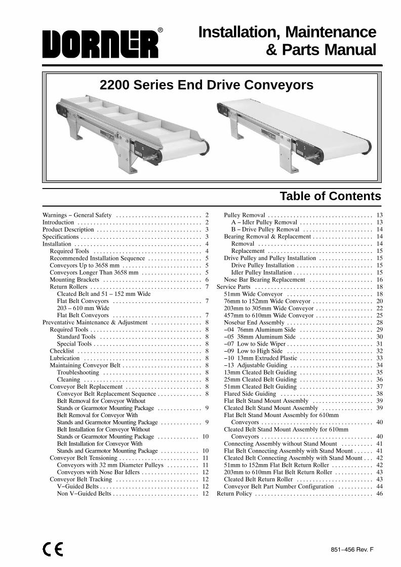
Installation, Maintenance & Parts Manual
2200 Series End Drive Conveyors
Table of ContentsWarnings − General Safety 2. . . . . . . . . . . . . . . . . . . . . . . . . . . Introduction 2. . . . . . . . . . . . . . . . . . . . . . . . . . . . . . . . . . . . . . . Product Description 3. . . . . . . . . . . . . . . . . . . . . . . . . . . . . . . . . Specifications 3. . . . . . . . . . . . . . . . . . . . . . . . . . . . . . . . . . . . . . Installation 4. . . . . . . . . . . . . . . . . . . . . . . . . . . . . . . . . . . . . . . .
Required Tools 4. . . . . . . . . . . . . . . . . . . . . . . . . . . . . . . . . . Recommended Installation Sequence 5. . . . . . . . . . . . . . . . . Conveyors Up to 3658 mm 5. . . . . . . . . . . . . . . . . . . . . . . . . Conveyors Longer Than 3658 mm 5. . . . . . . . . . . . . . . . . . . Mounting Brackets 6. . . . . . . . . . . . . . . . . . . . . . . . . . . . . . . Return Rollers 7. . . . . . . . . . . . . . . . . . . . . . . . . . . . . . . . . . .
Cleated Belt and 51 – 152 mm WideFlat Belt Conveyors 7. . . . . . . . . . . . . . . . . . . . . . . . . . . . 203 – 610 mm WideFlat Belt Conveyors 7. . . . . . . . . . . . . . . . . . . . . . . . . . . .
Preventative Maintenance & Adjustment 8. . . . . . . . . . . . . . . . Required Tools 8. . . . . . . . . . . . . . . . . . . . . . . . . . . . . . . . . . .
Standard Tools 8. . . . . . . . . . . . . . . . . . . . . . . . . . . . . . . . Special Tools 8. . . . . . . . . . . . . . . . . . . . . . . . . . . . . . . . . .
Checklist 8. . . . . . . . . . . . . . . . . . . . . . . . . . . . . . . . . . . . . . . Lubrication 8. . . . . . . . . . . . . . . . . . . . . . . . . . . . . . . . . . . . . Maintaining Conveyor Belt 8. . . . . . . . . . . . . . . . . . . . . . . . .
Troubleshooting 8. . . . . . . . . . . . . . . . . . . . . . . . . . . . . . . Cleaning 8. . . . . . . . . . . . . . . . . . . . . . . . . . . . . . . . . . . . .
Conveyor Belt Replacement 8. . . . . . . . . . . . . . . . . . . . . . . . Conveyor Belt Replacement Sequence 8. . . . . . . . . . . . . . Belt Removal for Conveyor WithoutStands or Gearmotor Mounting Package 9. . . . . . . . . . . . . . Belt Removal for Conveyor WithStands and Gearmotor Mounting Package 9. . . . . . . . . . . . . Belt Installation for Conveyor WithoutStands or Gearmotor Mounting Package 10. . . . . . . . . . . . . Belt Installation for Conveyor WithStands and Gearmotor Mounting Package 10. . . . . . . . . . . .
Conveyor Belt Tensioning 11. . . . . . . . . . . . . . . . . . . . . . . . . Conveyors with 32 mm Diameter Pulleys 11. . . . . . . . . . Conveyors with Nose Bar Idlers 12. . . . . . . . . . . . . . . . . .
Conveyor Belt Tracking 12. . . . . . . . . . . . . . . . . . . . . . . . . . V−Guided Belts 12. . . . . . . . . . . . . . . . . . . . . . . . . . . . . . . Non V−Guided Belts 12. . . . . . . . . . . . . . . . . . . . . . . . . . .
Pulley Removal 13. . . . . . . . . . . . . . . . . . . . . . . . . . . . . . . . . A − Idler Pulley Removal 13. . . . . . . . . . . . . . . . . . . . . . . B −Drive Pulley Removal 14. . . . . . . . . . . . . . . . . . . . . .
Bearing Removal & Replacement 14. . . . . . . . . . . . . . . . . . . Removal 14. . . . . . . . . . . . . . . . . . . . . . . . . . . . . . . . . . . . Replacement 15. . . . . . . . . . . . . . . . . . . . . . . . . . . . . . . . .
Drive Pulley and Pulley Installation 15. . . . . . . . . . . . . . . . . Drive Pulley Installation 15. . . . . . . . . . . . . . . . . . . . . . . . Idler Pulley Installation 15. . . . . . . . . . . . . . . . . . . . . . . . .
Nose Bar Bearing Replacement 16. . . . . . . . . . . . . . . . . . . . Service Parts 18. . . . . . . . . . . . . . . . . . . . . . . . . . . . . . . . . . . . .
51mm Wide Conveyor 18. . . . . . . . . . . . . . . . . . . . . . . . . . . 76mm to 152mm Wide Conveyor 20. . . . . . . . . . . . . . . . . . . 203mm to 305mm Wide Conveyor 22. . . . . . . . . . . . . . . . . . 457mm to 610mm Wide Conveyor 25. . . . . . . . . . . . . . . . . . Nosebar End Assembly 28. . . . . . . . . . . . . . . . . . . . . . . . . . . −04 76mm Aluminum Side 29. . . . . . . . . . . . . . . . . . . . . . . −05 38mm Aluminum Side 30. . . . . . . . . . . . . . . . . . . . . . . −07 Low to Side Wiper 31. . . . . . . . . . . . . . . . . . . . . . . . . . . −09 Low to High Side 32. . . . . . . . . . . . . . . . . . . . . . . . . . . −10 13mm Extruded Plastic 33. . . . . . . . . . . . . . . . . . . . . . . −13 Adjustable Guiding 34. . . . . . . . . . . . . . . . . . . . . . . . . . 13mm Cleated Belt Guiding 35. . . . . . . . . . . . . . . . . . . . . . . 25mm Cleated Belt Guiding 36. . . . . . . . . . . . . . . . . . . . . . . 51mm Cleated Belt Guiding 37. . . . . . . . . . . . . . . . . . . . . . . Flared Side Guiding 38. . . . . . . . . . . . . . . . . . . . . . . . . . . . . Flat Belt Stand Mount Assembly 39. . . . . . . . . . . . . . . . . . . Cleated Belt Stand Mount Assembly 39. . . . . . . . . . . . . . . . Flat Belt Stand Mount Assembly for 610mm
Conveyors 40. . . . . . . . . . . . . . . . . . . . . . . . . . . . . . . . . . . Cleated Belt Stand Mount Assembly for 610mm
Conveyors 40. . . . . . . . . . . . . . . . . . . . . . . . . . . . . . . . . . . Connecting Assembly without Stand Mount 41. . . . . . . . . . Flat Belt Connecting Assembly with Stand Mount 41. . . . . . Cleated Belt Connecting Assembly with Stand Mount 42. . . 51mm to 152mm Flat Belt Return Roller 42. . . . . . . . . . . . . 203mm to 610mm Flat Belt Return Roller 43. . . . . . . . . . . . Cleated Belt Return Roller 43. . . . . . . . . . . . . . . . . . . . . . . . Conveyor Belt Part Number Configuration 44. . . . . . . . . . .
Return Policy 46. . . . . . . . . . . . . . . . . . . . . . . . . . . . . . . . . . . . .
2200 Series End Drive Conveyor Installation, Maintenance & Parts Manual851-456 Rev. F 2 Dorner Mfg. Corp.
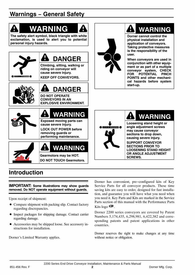
The safety alert symbol, black triangle with whiteexclamation, is used to alert you to potentialpersonal injury hazards.
Ç Ç
ÇÇÇÇClimbing, sitting, walking orriding on conveyor willcause severe injury.KEEP OFF CONVEYORS.
DANGER
ÇÇÇÇ
DANGERDO NOT OPERATECONVEYORS IN ANEXPLOSIVE ENVIRONMENT.
ÇÇÇÇExposed moving parts cancause severe injury.LOCK OUT POWER beforeremoving guards orperforming maintenance.
ÇÇ
Gearmotors may be HOT.DO NOT TOUCH Gearmotors.
ÇÇDorner cannot control thephysical installation andapplication of conveyors.Taking protective measuresis the responsibility of theuser.
When conveyors are used inconjunction with other equip-ment or as part of a multipleconveyor system, CHECKFOR POTENTIAL PINCHPOINTS and other mechani-cal hazards before systemstart-up.
ÇÇLoosening stand height orangle adjustment screwsmay cause conveyorsections to drop down,causing severe injury.SUPPORT CONVEYORSECTIONS PRIOR TOLOOSENING STAND HEIGHTOR ANGLE ADJUSTMENTSCREWS.
Introduction
IMPORTANT: Some illustrations may show guardsremoved. Do NOT operate equipment without guards.
Upon receipt of shipment:
� Compare shipment with packing slip. Contact factoryregarding discrepancies.
� Inspect packages for shipping damage. Contact carrierregarding damage.
� Accessories may be shipped loose. See accessory in-structions for installation.
Dorner’s Limited Warranty applies.
Dorner has convenient, pre−configured kits of KeyService Parts for all conveyor products. These timesaving kits are easy to order, designed for fast installa-tion, and guarantee you will have what you need whenyou need it. Key Parts and Kits are marked in the ServiceParts section of this manual with the Performance PartsKits logo .
Dorner 2200 series conveyors are covered by PatentNumbers 5,174,435, 6,298,981, 6,422,382 and corre-sponding patents and patent applications in othercountries.
Dorner reserves the right to make changes at any timewithout notice or obligation.
Warnings − General Safety

2200 Series End Drive Conveyor Installation, Maintenance & Parts ManualDorner Mfg. Corp. 3 851-456 Rev. F
Refer to Figure 1 for typical conveyor components.
A ConveyorB Gearmotor Mounting PackageC GearmotorD Guiding & AccessoriesE Mounting BracketsF Return RollersG Support StandH Variable Speed ControllerI Drive EndJ Idler/Tension End
Typical Components
Figure 1
A
B C D
EE
J
F
G
H
I
SpecificationsModels:Flat Belt 2200 Series Conveyor
1 = with belt tracking cams and mounting brackets 2 = with V-guide tracking and mounting brackets3 = with nosebar transfer tail and mounting brackets4 = with V−guide tracking and no mounting brackets5 = with belt tracking cams and no mounting brackets6 = with nosebar transfer tail and no mounting brackets
Conveyor Width ReferenceConveyor Length Reference
Belt Type*
Output Shaft Position*Conveyor Profile*
Document Language, M = English
2 1 0 M WW LLLL A PP BB
Pulley Type:0 = Standard 32mm Dia.1 = Gang Drive 25mm Dia.
Cleated Belt 2200 Series Conveyor
Conveyor Width Reference
Conveyor Length Reference
2 4 C M WW LLLL A SSSS
Output Shaft Position*
Cleat Spacing*
0 = with V-guide tracking and no mounting brackets4 = with V-guide tracking and mounting brackets5 = with belt tracking cams and mounting brackets9 = with belt tracking cams and no mounting brackets
Document Language, M = English
Cleat Type*
* See Ordering and Specifications Catalog for details.
Conveyor Supports:Maximum Distances:
K = 457 mm**L = 1829 mm***M = 457 mm
** For Heavy Load Bottom Mount Package, mount support under gear head.
*** For conveyors longer than 3658 mm, installsupport at joint.
LK M
Figure 2
Product Description

2200 Series End Drive Conveyor Installation, Maintenance & Parts Manual851-456 Rev. F 4 Dorner Mfg. Corp.
Specifications:Conveyor WidthReference (WW) 02 03 04 05 06 08 10 12 18 21 24
Conveyor Belt Width 44mm 70mm 95mm 127mm 152mm 203mm 254mm 305mm 457mm 533mm 609mm
Maximum ConveyorLoad*
(See NOTE Below)14kg 16kg 19kg 23kg 27kg 32kg 36kg 36kg 36kg 36kg 36kg
Conveyor StartupTorque*
0.5Nm 0.6Nm 0.7Nm 0.8Nm 0.9Nm 1.1Nm 1.4Nm 1.5Nm 1.7Nm 2.0Nm 2.3Nm
Belt Travel 88 mm per revolution of pulley
Maximum Belt Speed* 80.5 m/minute
Belt Takeup 10 mm of stroke = 19 mm of belt take-up
Conveyor LengthReference (LL) 02 03 04 05 06 07 08 09 10 11 12 13** 14** 15** 16** 17** 18**
Conveyor Length
Up to 5486 mm in anylength to nearest 3mm
610 mm
914 mm
1219 mm
1524 mm
1829 mm
2134 mm
2438 mm
2743 mm
3048 mm
3353 mm
3658 mm
3962 mm
**
4267 mm
**
4572 mm
**
4877 mm
**
5182 mm
**
5486 mm
**
NOTE: Maximum conveyor loads based on:
� Non-accumulating product
� Product moving towards gearmotor
� Conveyor being mounted horizontal
* See Ordering and Specifications Catalog for details.
** Lengths available only in 152 mm & widerconveyors.
Installation
NOTE: Conveyor MUST be mounted straight, flat andlevel within confines of conveyor. Use a level (N ofFigure 3) for setup.
Figure 3
N
O Conveyor frame (two sections if longer than 3658 mm)P Conveyor brackets (4x)Q Return rollers (for longer conveyors)
Installation Component List
Required Tools� Hex-key wrenches:
4 mm, 5 mm
� Level
� Torque wrench
Specifications
2200 Series End Drive Conveyor Installation, Maintenance & Parts ManualDorner Mfg. Corp. 5 851-456 Rev. F
Recommended Installation Sequence� Install support stands (see accessory instructions)
� Assemble conveyor (if required)
� Attach mounting brackets to conveyor
� Attach conveyor to stands
� Install return rollers on conveyor (optional)
� Mount gearmotor mounting package (see accessoryinstructions)
� Attach guides/accessories (see page 29 through 37 of“Service Parts” section for details)
Conveyors Up to 3658 mmNo assembly is required. Install mounting brackets andreturn rollers. Refer to “Mounting Brackets” on page 6and “Return Rollers” on page 7.
Conveyors Longer Than 3658 mm1. Locate conveyor sections (O Figure 4)
Figure 4
O
O
2. On tension end of the conveyor, identified with a
label (R of Figure 5), push in head plateassembly (S): On both sides of conveyor, loosen andmove cam tracking assemblies (T) (if equipped)away from head plates, then loosen fastening screws(U) and push head plate assembly inward.
Figure 5
R
U
S
T
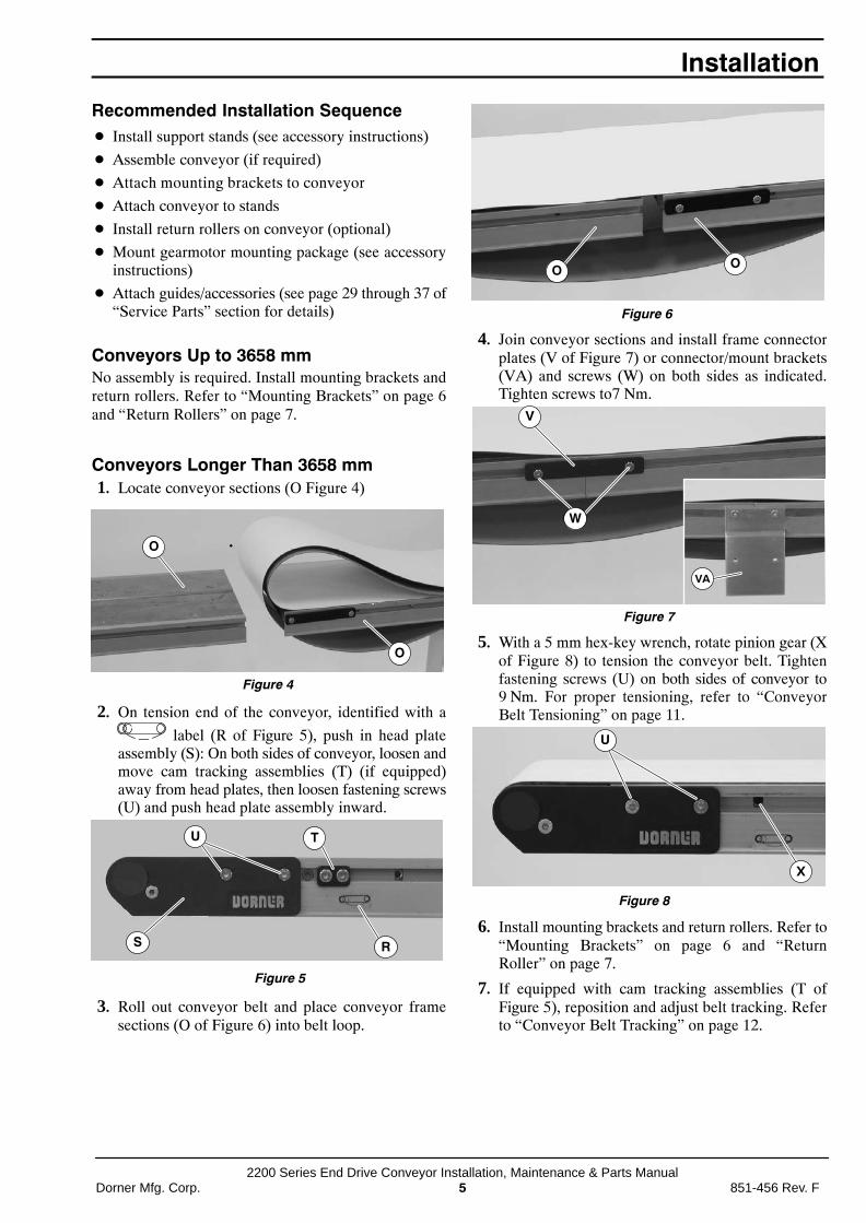
3. Roll out conveyor belt and place conveyor framesections (O of Figure 6) into belt loop.
Figure 6
O O
4. Join conveyor sections and install frame connectorplates (V of Figure 7) or connector/mount brackets(VA) and screws (W) on both sides as indicated.Tighten screws to7 Nm.
Figure 7
V
W
VA
5. With a 5 mm hex-key wrench, rotate pinion gear (Xof Figure 8) to tension the conveyor belt. Tightenfastening screws (U) on both sides of conveyor to9 Nm. For proper tensioning, refer to “ConveyorBelt Tensioning” on page 11.
Figure 8
X
U
6. Install mounting brackets and return rollers. Refer to“Mounting Brackets” on page 6 and “ReturnRoller” on page 7.
7. If equipped with cam tracking assemblies (T ofFigure 5), reposition and adjust belt tracking. Referto “Conveyor Belt Tracking” on page 12.
Installation
2200 Series End Drive Conveyor Installation, Maintenance & Parts Manual851-456 Rev. F 6 Dorner Mfg. Corp.
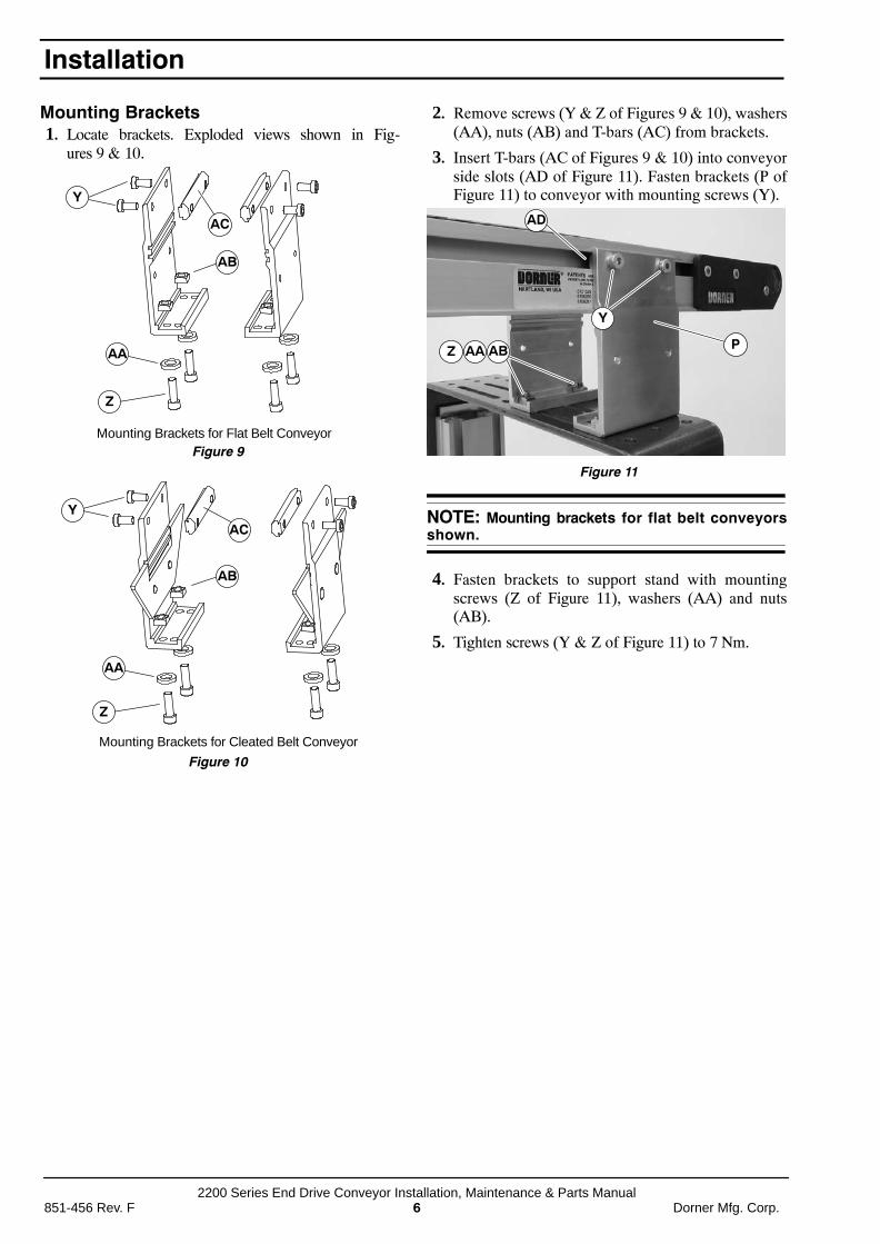
Mounting Brackets1. Locate brackets. Exploded views shown in Fig-
ures 9 & 10.
Figure 9
Y
AC
AB
AA
Z
Mounting Brackets for Flat Belt Conveyor
Figure 10
Y
AC
AB
AA
Z
Mounting Brackets for Cleated Belt Conveyor
2. Remove screws (Y & Z of Figures 9 & 10), washers(AA), nuts (AB) and T-bars (AC) from brackets.
3. Insert T-bars (AC of Figures 9 & 10) into conveyorside slots (AD of Figure 11). Fasten brackets (P ofFigure 11) to conveyor with mounting screws (Y).
Figure 11
AAZ
AD
Y
PAB
NOTE: Mounting brackets for flat belt conveyorsshown.
4. Fasten brackets to support stand with mountingscrews (Z of Figure 11), washers (AA) and nuts(AB).
5. Tighten screws (Y & Z of Figure 11) to 7 Nm.
Installation
2200 Series End Drive Conveyor Installation, Maintenance & Parts ManualDorner Mfg. Corp. 7 851-456 Rev. F
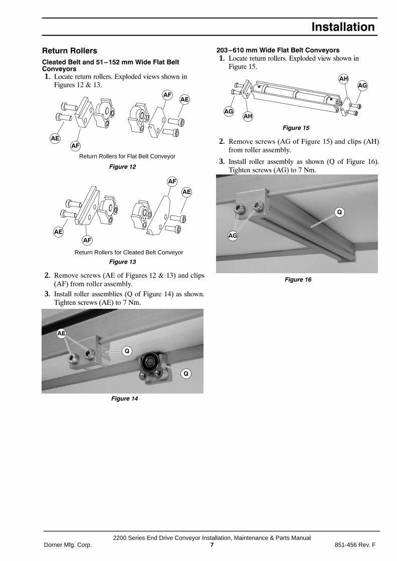
Return RollersCleated Belt and 51–152 mm Wide Flat BeltConveyors1. Locate return rollers. Exploded views shown in
Figures 12 & 13.
Figure 12
AEAF
AEAF
Return Rollers for Flat Belt Conveyor
Figure 13
Return Rollers for Cleated Belt Conveyor
AFAE
AF
AE
2. Remove screws (AE of Figures 12 & 13) and clips(AF) from roller assembly.
3. Install roller assemblies (Q of Figure 14) as shown.Tighten screws (AE) to 7 Nm.
Figure 14
AE
Q
Q
203–610 mm Wide Flat Belt Conveyors1. Locate return rollers. Exploded view shown in
Figure 15.
Figure 15
AGAH
AGAH
2. Remove screws (AG of Figure 15) and clips (AH)from roller assembly.
3. Install roller assembly as shown (Q of Figure 16).Tighten screws (AG) to 7 Nm.
Figure 16
AG
Q
Installation
2200 Series End Drive Conveyor Installation, Maintenance & Parts Manual851-456 Rev. F 8 Dorner Mfg. Corp.
Required ToolsStandard Tools� Hex-key wrenches:
2.5 mm, 4 mm, 5 mm
� Arbor press
Special Tools� 807−1078 Bearing Puller Tool (or equivalent)
� 450292 Bearing Installation Tool
� 456070 Bearing Removal Tool
Checklist� Keep service parts on hand (see “Service Parts” sec-
tion for recommendations)
� Keep supply of belt cleaner (part # 625619)
� Clean entire conveyor and knurled pulley while dis-assembled
� Replace worn or damaged parts
LubricationNo lubrication is required. Replace bearings if worn.
Maintaining Conveyor Belt
TroubleshootingInspect conveyor belt for:
� Surface cuts or wear
� Stalling or slipping
� Damage to V-guide
Surface cuts and wear indicate:
� Sharp or heavy parts impacting belt
� Jammed parts
� Improperly installed bottom wipers (if installed)
� Accumulated dirt in wipers (if installed)
� Foreign material inside the conveyor
� Improperly positioned accessories
� Bolt-on guiding is pinching belt
Stalling or slipping indicates:
� Excessive load on belt
� Conveyor belt or drive timing belt are not properlytensioned
� Worn knurl or impacted dirt on drive pulley
� Intermittent jamming or drive train problems
Damage to V-guide indicates:
� Twisted or damaged conveyor frame
� Dirt impacted on pulleys
� Excessive or improper side loading
NOTE: Visit www.dorner.com for complete list oftroubleshooting solutions.
Cleaning
IMPORTANT: Do not use belt cleaners that containalcohol, acetone, Methyl Ethyl Ketone (MEK) or otherharsh chemicals.
Use Dorner Belt Cleaner (part # 625619). Mild soap andwater may also be used. Do not soak the belt.
For /05 woven polyester and /06 black anti-static belts,use a bristled brush to improve cleaning.
Conveyor Belt Replacement
ÇÇExposed moving parts cancause severe injury.LOCK OUT POWER beforeremoving guards orperforming maintenance.
Conveyor Belt Replacement Sequence� Remove old conveyor belt:
-Conveyor without Stands or Gearmotor MountingPackage
-Conveyor with Stands and Gearmotor MountingPackage
� Install new conveyor belt
� Tension conveyor belt
Preventive Maintenance and Adjustment

2200 Series End Drive Conveyor Installation, Maintenance & Parts ManualDorner Mfg. Corp. 9 851-456 Rev. F
Belt Removal for Conveyor Without Stands orGearmotor Mounting Package1. If equipped, remove bottom wipers (AJ of Figure
17): Remove fastening screws (AI) then removewiper (AJ).
Figure 17
AJ
AIAI
2. If equipped, remove return rollers and guiding andaccessories from one side of conveyor.
3. On tension end of the conveyor, identified with a
label (R of Figure 18), push in head plateassembly (S): On both sides of conveyor, loosen andmove cam tracking assemblies (T) (if equipped)away from head plates, then loosen fastening screws(U) and push head plate assembly inward.
Figure 18
R
U
S
T
4. Remove conveyor belt.
Belt Removal for Conveyor With Stands andGearmotor Mounting Package
ÇÇRemoving mounting brackets
without support under gear-motor will cause conveyor totip, causing severe injury.PROVIDE SUPPORT UNDER-NEATH THE GEARMOTORWHEN CHANGING THE BELT
1. Place temporary support stands (AK of Figure 19) atboth ends of the conveyor. Place an additionalsupport stand under the drive motor (AL), ifequipped. See WARNING.
Figure 19
AK
AL
AK
AM
AM
2. Remove mounting brackets (AM of Figure 19) fromone side of conveyor. (Reverse steps 3 & 4 of“Mounting Brackets” section on page 6.) Ifequipped with heavy load drive package, removebrackets from side opposite drive cover (AN ofFigure 20).
3. If equipped, remove bottom wipers (AJ of Figure17): Remove fastening screws (AI) then removewiper (AJ).
4. If equipped, remove return rollers, guiding andaccessories from side opposite drive cover (AN ofFigure 20).
Figure 20
AP
AN
AO
AO
5. If equipped with heavy load drive package, removedrive support bracket (AP of Figure 20): Removebracket screws (AO) then remove bracket (AP).
Preventive Maintenance and Adjustment

2200 Series End Drive Conveyor Installation, Maintenance & Parts Manual851-456 Rev. F 10 Dorner Mfg. Corp.
6. On tension end of the conveyor, identified with a
label (R of Figure 21), push in head plateassembly (S): On both sides of conveyor, loosen andmove cam tracking assemblies (T) (if equipped)away from head plates, then loosen fastening screws(U) and push head plate assembly inward.
Figure 21
R
U
S
T
7. Remove belt (AQ of Figure 22) from conveyor.
Figure 22
AQ
AQ
Belt Installation for Conveyor without Stands orGearmotor Mounting Package1. Orient belt so splice leading fingers (AR of Fig-
ure 23) point in the direction of belt travel as identi-fied by the conveyor directional label (AS).
Figure 23
AR
AS
2. Slide belt onto the conveyor frame assembly.
3. Tension belt. Refer to “Conveyor Belt Tensioning” onpage 11.
4. If equipped, install wipers, return rollers and guid-ing.
Belt Installation for Conveyor with Stands andGearmotor Mounting Package
ÇÇRemoving mounting bracketswithout support under gear-motor will cause conveyor totip, causing severe injury.PROVIDE SUPPORT UNDER-NEATH THE GEARMOTORWHEN CHANGING THE BELT
1. Ensure temporary support stands (AK of Figure 19)are placed at both ends of the conveyor. Place anadditional support stand under the drive motor (AL),if equipped. See WARNING.
2. Orient belt so splice leading fingers (AR of Fig-ure 23) point in the direction of belt travel as identi-fied by the conveyor directional label (AS).
3. Install belt (AQ of Figure 24) on conveyor. Liftconveyor slightly to avoid pinching belt on tempo-rary support stands.
Figure 24
AQ
AQ
4. Re-install conveyor mounting brackets. Refer“Mounting Brackets” on page 6, steps 3 through 5.
5. If equipped with a heavy load drive package,re-install drive support bracket (AP of Figure 20).
6. Tension belt. Refer to “Conveyor Belt Tensioning” onpage 11.
7. If equipped, re-install wipers, return rollers andguiding.
Preventive Maintenance and AdjustmentPreventive Maintenance and Adjustment

2200 Series End Drive Conveyor Installation, Maintenance & Parts ManualDorner Mfg. Corp. 11 851-456 Rev. F
Conveyor Belt Tensioning
ÇExposed moving parts cancause severe injury.LOCK OUT POWER beforeremoving guards orperforming maintenance.
Conveyors with 32 mm Diameter Pulleys1. On tension end of the conveyor, identified with a
label (R of Figure 25), adjust head plateassembly (S): On both sides of conveyor, loosenfastening screws (U) and rotate pinion gear (X) toadjust head plate assembly.
Figure 25
R
U
S X
T
2. Adjust head plate assembly so end of conveyorframe aligns with or between the head plate tension-ing marks (AT & AU of Figure 26). Replace belt ifproper tensioning can not be obtained while aligning
the end of the conveyor frame with or between thetensioning marks. See NOTE.
Figure 26
AUAT
NOTE: On pinion gear, do not exceed a torque of 2.8 Nm for 44 – 305 mm wide conveyors and 4.5 Nmfor a 457 – 610 mm wide conveyor. Over tensioningthe conveyor belt could cause excessive pulleybearing load and early failure.
3. After adjusting proper tensioning, tighten fasteningscrews (U of Figure 25) on both sides of conveyor to7 Nm.
4. If equipped with cam tracking assemblies (T ofFigure 25), position against head plates and adjustbelt tracking. Refer to “Conveyor Belt Tracking” onpage 12.
Preventive Maintenance and Adjustment
2200 Series End Drive Conveyor Installation, Maintenance & Parts Manual851-456 Rev. F 12 Dorner Mfg. Corp.
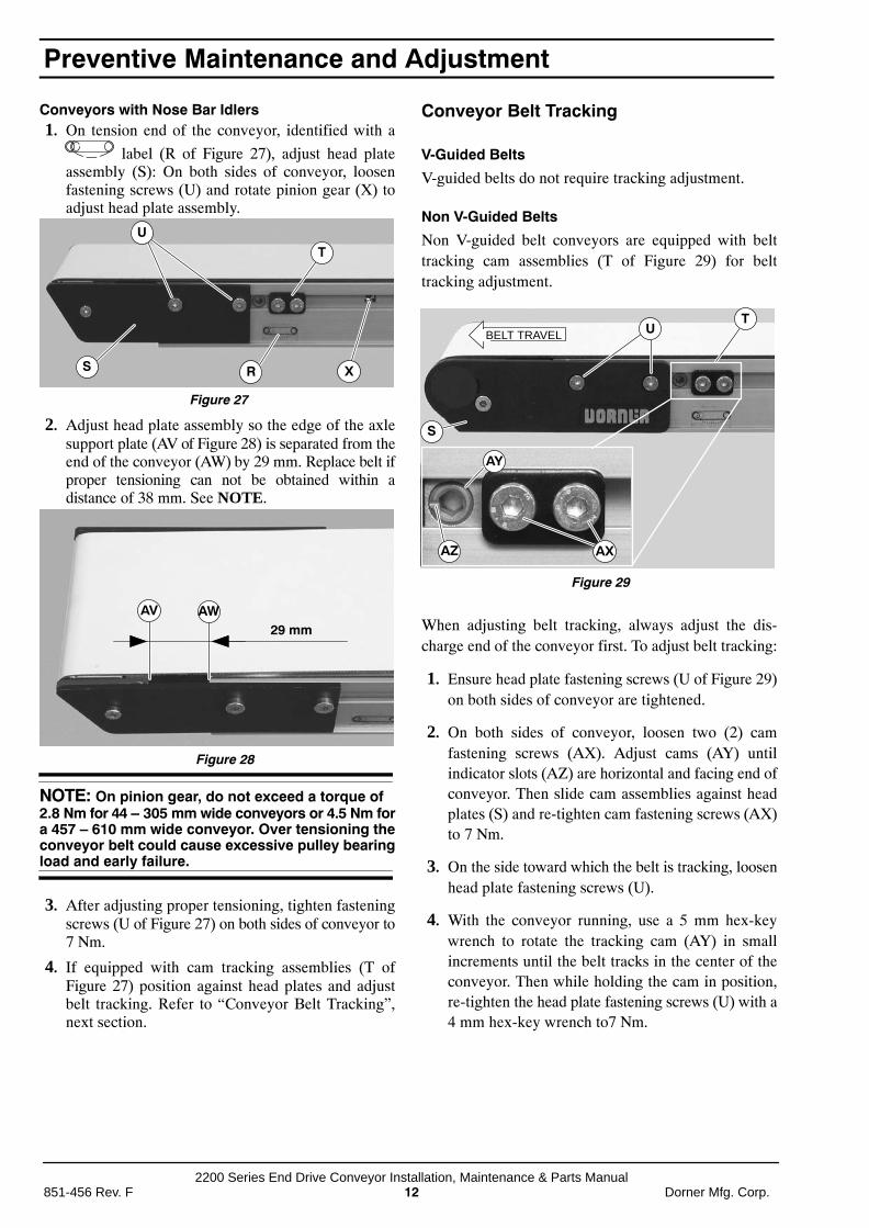
Conveyors with Nose Bar Idlers1. On tension end of the conveyor, identified with a
label (R of Figure 27), adjust head plateassembly (S): On both sides of conveyor, loosenfastening screws (U) and rotate pinion gear (X) toadjust head plate assembly.
Figure 27
X
U
RS
T
2. Adjust head plate assembly so the edge of the axlesupport plate (AV of Figure 28) is separated from theend of the conveyor (AW) by 29 mm. Replace belt ifproper tensioning can not be obtained within adistance of 38 mm. See NOTE.
Figure 28
AV AW29 mm
NOTE: On pinion gear, do not exceed a torque of 2.8 Nm for 44 – 305 mm wide conveyors or 4.5 Nm fora 457 – 610 mm wide conveyor. Over tensioning theconveyor belt could cause excessive pulley bearingload and early failure.
3. After adjusting proper tensioning, tighten fasteningscrews (U of Figure 27) on both sides of conveyor to7 Nm.
4. If equipped with cam tracking assemblies (T ofFigure 27) position against head plates and adjustbelt tracking. Refer to “Conveyor Belt Tracking”,next section.
Conveyor Belt Tracking
V-Guided Belts
V-guided belts do not require tracking adjustment.
Non V-Guided Belts
Non V-guided belt conveyors are equipped with belttracking cam assemblies (T of Figure 29) for belttracking adjustment.
Figure 29
AX
T
AZ
AY
UBELT TRAVEL
S
When adjusting belt tracking, always adjust the dis-charge end of the conveyor first. To adjust belt tracking:
1. Ensure head plate fastening screws (U of Figure 29)on both sides of conveyor are tightened.
2. On both sides of conveyor, loosen two (2) camfastening screws (AX). Adjust cams (AY) untilindicator slots (AZ) are horizontal and facing end ofconveyor. Then slide cam assemblies against headplates (S) and re-tighten cam fastening screws (AX)to 7 Nm.
3. On the side toward which the belt is tracking, loosenhead plate fastening screws (U).
4. With the conveyor running, use a 5 mm hex-keywrench to rotate the tracking cam (AY) in smallincrements until the belt tracks in the center of theconveyor. Then while holding the cam in position,re-tighten the head plate fastening screws (U) with a4 mm hex-key wrench to7 Nm.
Preventive Maintenance and Adjustment

2200 Series End Drive Conveyor Installation, Maintenance & Parts ManualDorner Mfg. Corp. 13 851-456 Rev. F
Pulley Removal
ÇExposed moving parts cancause severe injury.LOCK OUT POWER beforeremoving guards orperforming maintenance.
Leaving the conveyor belt in place, remove the desiredpulley following the corresponding instructions below:
� A − Idler Pulley Removal
� B − Drive Pulley Removal
A − Idler Pulley Removal1. On one side of the conveyor, loosen two (2) head
plate fastening screws (U of Figure 30) and removethem.
NOTE: To prevent damage to the head plates andpulley, be sure to remove them slowly because theyare not attached to pulley.
Figure 30
U
2. Remove the head plate (BA of Figure 31) from theconveyor frame.
Figure 31BA
3. Pulley will slide out of opposite head plate and dropinto slack of belt (Figure 32).
Figure 32
4. Slide spindle out of the belt loop.
Preventive Maintenance and Adjustment
2200 Series End Drive Conveyor Installation, Maintenance & Parts Manual851-456 Rev. F 14 Dorner Mfg. Corp.
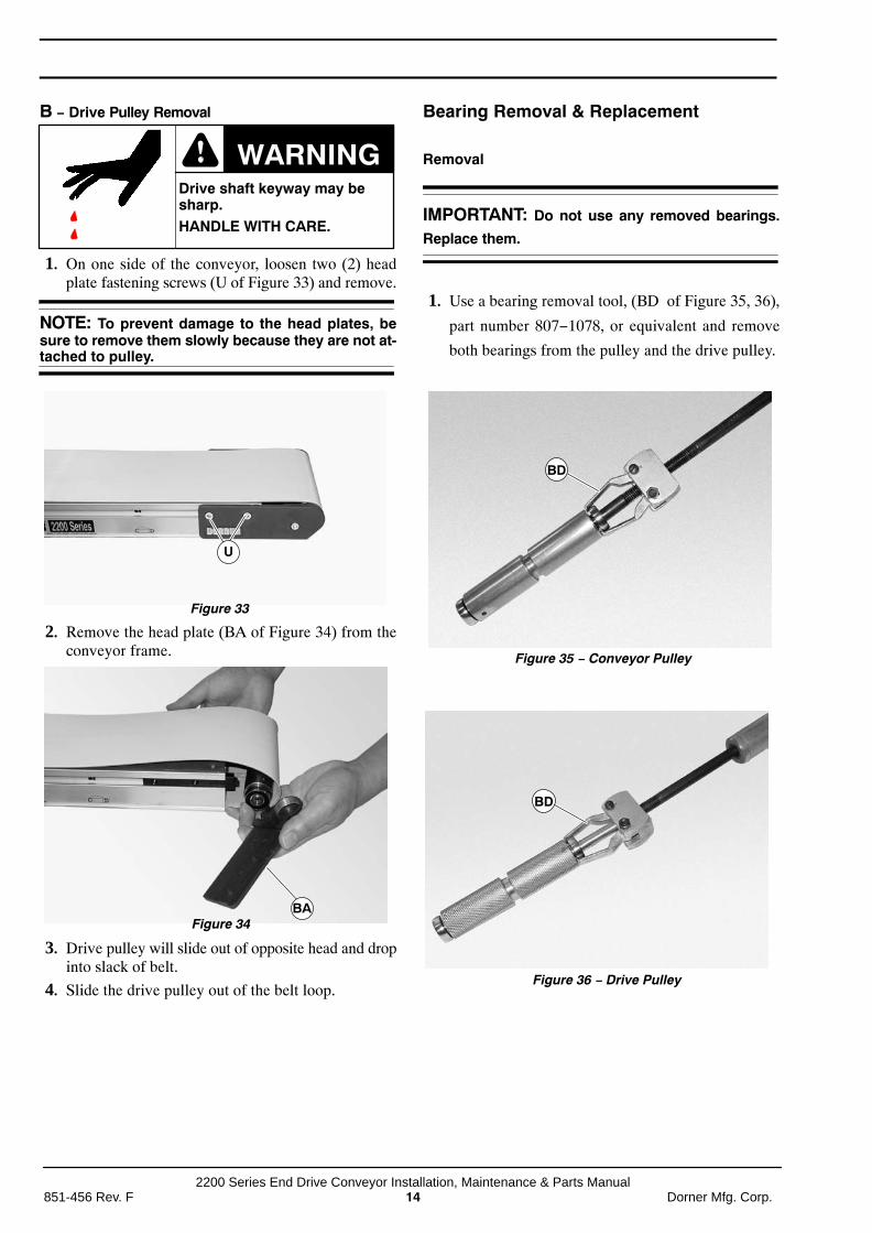
B − Drive Pulley Removal
ÇÇDrive shaft keyway may besharp.HANDLE WITH CARE.
1. On one side of the conveyor, loosen two (2) headplate fastening screws (U of Figure 33) and remove.
NOTE: To prevent damage to the head plates, besure to remove them slowly because they are not at-tached to pulley.
Figure 33
U
2. Remove the head plate (BA of Figure 34) from theconveyor frame.
Figure 34BA
3. Drive pulley will slide out of opposite head and dropinto slack of belt.
4. Slide the drive pulley out of the belt loop.
Bearing Removal & Replacement
Removal
IMPORTANT: Do not use any removed bearings.
Replace them.
1. Use a bearing removal tool, (BD of Figure 35, 36),
part number 807−1078, or equivalent and remove
both bearings from the pulley and the drive pulley.
Figure 35 − Conveyor Pulley
BD
Figure 36 − Drive Pulley
BD

2200 Series End Drive Conveyor Installation, Maintenance & Parts ManualDorner Mfg. Corp. 15 851-456 Rev. F
Replacement
1. Inspect the head plates bearing seating surface (BCof Figure 37). If they are worn or damaged, replacethe head. See ”Service Parts” on Page 20.
Figure 37
BC
NOTE: Two washers may be required when instal-ling the bearing over the drive shaft on the drivepulley, if the bearing installation tool is not longenough to fit the length of the drive shaft.
2. Use a bearing installation tool, (BE of Figure 38),part number 450292 or equivalent and press bearingsonto the pulley and drive pulley.
Figure 38
BE
Drive Pulley and Pulley Installation
Drive Pulley Installation1. With opposite head plate installed, position the drive
pulley through the loop of the belt, into the oppositehead plate.
Figure 39
BA
2. Place the head plate (BA of Figure 39) and attach thehead plate to the conveyor frame with the two (2)screws removed. Tighten screws 7Nm.
Idler Pulley Installation1. With opposite head plate installed, position the idler
pulley through the loop of the belt, into the oppositehead plate.
Figure 40
BA
2. Place the head plate (BA of Figure 40) and attach thehead plate to the conveyor frame with the two (2)screws removed and hand tighten.
2200 Series End Drive Conveyor Installation, Maintenance & Parts Manual851-456 Rev. F 16 Dorner Mfg. Corp.
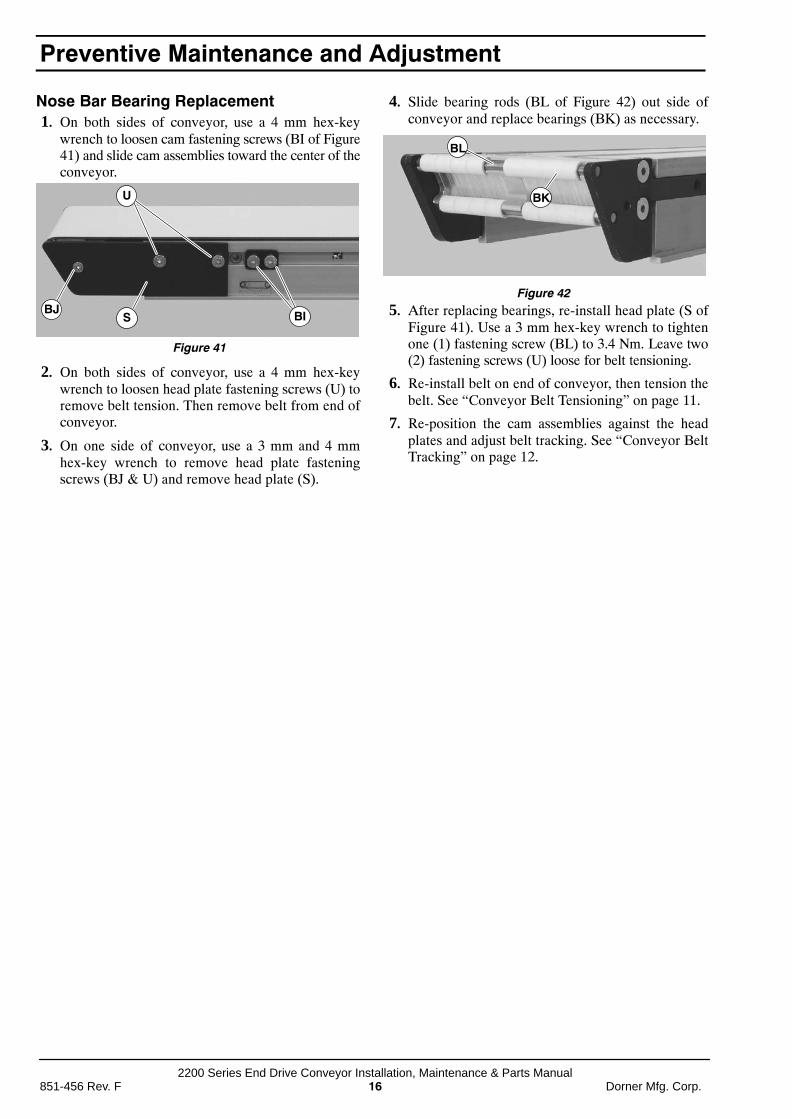
Nose Bar Bearing Replacement1. On both sides of conveyor, use a 4 mm hex-key
wrench to loosen cam fastening screws (BI of Figure41) and slide cam assemblies toward the center of theconveyor.
Figure 41
U
BJBIS
2. On both sides of conveyor, use a 4 mm hex-keywrench to loosen head plate fastening screws (U) toremove belt tension. Then remove belt from end ofconveyor.
3. On one side of conveyor, use a 3 mm and 4 mmhex-key wrench to remove head plate fasteningscrews (BJ & U) and remove head plate (S).
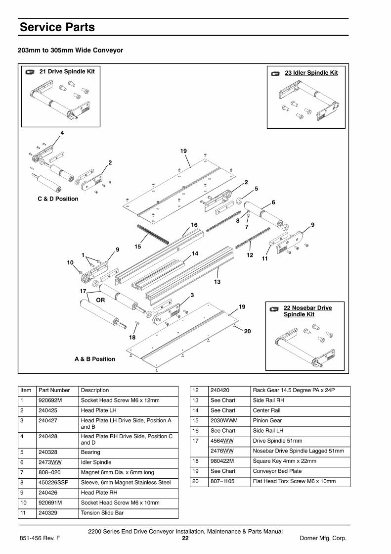
4. Slide bearing rods (BL of Figure 42) out side ofconveyor and replace bearings (BK) as necessary.
Figure 42
BK
BL
BK
5. After replacing bearings, re-install head plate (S ofFigure 41). Use a 3 mm hex-key wrench to tightenone (1) fastening screw (BL) to 3.4 Nm. Leave two(2) fastening screws (U) loose for belt tensioning.
6. Re-install belt on end of conveyor, then tension thebelt. See “Conveyor Belt Tensioning” on page 11.
7. Re-position the cam assemblies against the headplates and adjust belt tracking. See “Conveyor BeltTracking” on page 12.
Preventive Maintenance and Adjustment

2200 Series End Drive Conveyor Installation, Maintenance & Parts ManualDorner Mfg. Corp. 17 851-456 Rev. F
Notes

2200 Series End Drive Conveyor Installation, Maintenance & Parts Manual851-456 Rev. F 18 Dorner Mfg. Corp.
NOTE: For replacement parts other than those shown in this section, contact an authorized Dorner ServiceCenter or the factory. Key Service Parts and Kits are identified by the Performance Parts Kits logo . Dornerrecommends keeping these parts on hand.
51mm Wide Conveyor
18 Drive Spindle Kit 20 Idler Spindle Kit19 Nosebar DriveSpindle Kit
17
C & D Position
A & B Position
9
15
163
OR
1413
12
11 10
978
6
5
22
4
1
Service Parts

2200 Series End Drive Conveyor Installation, Maintenance & Parts ManualDorner Mfg. Corp. 19 851-456 Rev. F
Item Part Number Description
1 920692M Socket Head Screw M6 x 12mm
2 240425 Head Plate LH
3 240427 Head Plate LH Drive Side, PositionA and B
4 240428 Head Plate RH Drive Side, Posi-tion C and D
5 240328 Bearing
6 247302 Idler Spindle 51mm
7 808−020 Magnet 6.35mm Dia. x 6.35mmlong
8 450226SSP Sleeve, 6.35mm Magnet StainlessSteel
9 240426 Head Plate RH
10 920691M Socket Head Screw M6 x 10mm
11 240329 Tension Slide Bar
12 240420 Rack Gear 14.5 Degree PA x 24 P
13 240423 Pinion 51mm
14 240422 Pinion Pin
15 456402 Drive Spindle 51mm
247602 Nosebar Drive Spindle Lagged51mm
16 980422M Square Key 4mm x 22mm
17 See FrameChart
51mm Frame
18 22A−02 Drive Spindle Kit, Position A and B− Grooved (Includes Items 1, 2, 3,5, 9 and 15)
22D−02 Drive Spindle Kit, Position C and D− Grooved (Includes Items 1, 2, 4,5, 9 and 15)
19 22NA−02 Nosebar Drive Spindle Kit, PositionA and B − Lagged, Smooth (In-cludes Items 1, 2, 3, 5, 9 and 15)
22ND−02 Nosebar Drive Spindle Kit, PositionC and D − Lagged, Smooth (In-cludes Items 1,2, 4, 5, 9 and 15)
20 22T−02 Idler Spindle Kit (Includes Items 1,2 and 5 through 10)
Item 17: 51mm Conveyor Frame
Length Part Number
610mm 240402−01908
914mm 240402−03108
1219mm 240402−04308
1524mm 240402−05508
1829mm 240402−06708
2134mm 240402−07908
2438mm 240402−09108
2743mm 240402−10308
3048mm 240402−11508
3353mm 240402−12708
3658mm 240402−13908
Service Parts

2200 Series End Drive Conveyor Installation, Maintenance & Parts Manual851-456 Rev. F 20 Dorner Mfg. Corp.
76mm to 152mm Wide Conveyor
20 Drive Spindle Kit
22 Idler Spindle Kit
21 Nosebar DriveSpindle Kit
C & D Position
A & B Position
2
1819
1
2
5
6
9
7
12
17
11 10
81314
3
16
9
4
15
OR
Service Parts

2200 Series End Drive Conveyor Installation, Maintenance & Parts ManualDorner Mfg. Corp. 21 851-456 Rev. F
Item Part Number Description
1 920692M Socket Head Screw M6 x 12mm
2 240425 Head Plate LH
3 240427 Head Plate LH Drive Side, Position Aand B
4 240428 Head Plate RH Drive Side, Position Cand D
5 240328 Bearing
6 2473WW Idler Spindle
7 808−020 Magnet 6mm Dia. x 6mm long
8 450226SSP Sleeve, 6mm Magnet Stainless Steel
9 240426 Head Plate RH
10 920691M Socket Head Screw M6 x 10mm
11 240329 Tension Slide Bar
12 240420 Rack Gear 14.5 Degree PA x 24P
13 240421 Pinion Bushing
14 2030WWM Pinion Gear
15 4564WW Drive Spindle 51mm
2476WW Nosebar Drive Spindle Lagged 51mm
16 980422M Square Key 4mm x 22mm
17 See FrameChart
Conveyor Frame
18 See Bed PlateChart
Conveyor Bed Plate
19 807−1105 Flat Head Torx Screw M6 x 10mm
20 22A−WW Drive Spindle Kit, Position A and B −Grooved (Includes Items 1,2, 3, 5, 9and 15)
22D−WW Drive Spindle Kit, Position C and D −Grooved (Includes Items 1, 2, 4, 5, 9and 15)
21 22NA−WW Nosebar Drive Spindle Kit, Position Aand B − Lagged, Smooth (IncludesItems 1, 2, 3, 5, 9 and 15)
22ND−WW Nosebar Drive Spindle Kit, Position Cand D − Lagged, Smooth (IncludesItems 1, 2, 4, 5, 9 and 15)
22 22T−WW Idler Spindle Kit (Includes Items 1, 2and 5 through 10)
WW = Conveyor width reference: 03, 04, 05, 06
Item 17: Conveyor Frame
Length Part Number
610mm 2404WW−01908
914mm 2404WW−03108
1219mm 2404WW−04308
1524mm 2404WW−05508
1829mm 2404WW−06708
2134mm 2404WW−07908
2438mm 2404WW−09108
2743mm 2404WW−10308
3048mm 2404WW−11508
3353mm 2404WW−12708
3658mm 2404WW−13908
3962mm 2404WW−07200 2404WW−07908*
4267mm 2404WW−07200 2404WW−09108*
4572mm 2404WW−07200 2404WW−10308*
4877mm 2404WW−07200 2404WW−11508*
5182mm 2404WW−07200 2404WW−12708*
5486mm 2404WW−07200 2404WW−13908*
WW = Conveyor width reference: 03, 04, 05, 06* = 152mm and wider conveyors, only
Item 18: Bed Plate
Length Part Number
610mm 2405WW−01900
914mm 2405WW−03100
1219mm 2405WW−04300
1524mm 2405WW−05500
1829mm 2405WW−06700
2134mm 2405WW−07900
2438mm 2405WW−09100
2743mm 2405WW−10300
3048mm 2405WW−11500
3353mm 2405WW−12700
3658mm 2405WW−13900
3962mm 2405WW−07196 2405WW−07900*
4267mm 2405WW−07196 2405WW−09100*
4572mm 2405WW−07196 2405WW−10300*
4877mm 2405WW−07196 2405WW−11500*
5182mm 2405WW−07196 2405WW−12700*
5486mm 2405WW−07196 2405WW−13900*
WW = Conveyor Width reference: 03, 04, 05, 06* = 152mm and wider conveyors, only
Service Parts
2200 Series End Drive Conveyor Installation, Maintenance & Parts Manual851-456 Rev. F 22 Dorner Mfg. Corp.
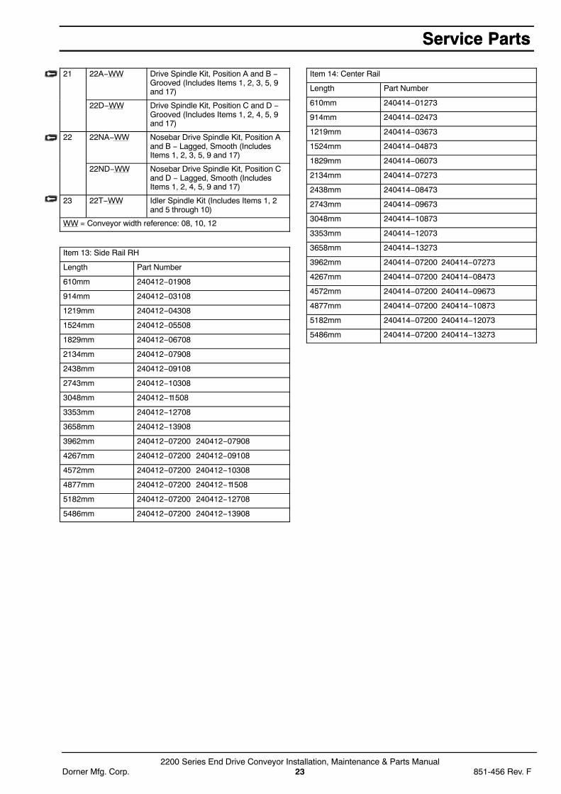
203mm to 305mm Wide Conveyor
21 Drive Spindle Kit
22 Nosebar DriveSpindle Kit
23 Idler Spindle Kit
C & D Position
A & B Position
2
19
1
3
19
20
10
18
4
1112
13
1415
78
6
52
9
17
OR
9
16
Item Part Number Description
1 920692M Socket Head Screw M6 x 12mm
2 240425 Head Plate LH
3 240427 Head Plate LH Drive Side, Position Aand B
4 240428 Head Plate RH Drive Side, Position Cand D
5 240328 Bearing
6 2473WW Idler Spindle
7 808−020 Magnet 6mm Dia. x 6mm long
8 450226SSP Sleeve, 6mm Magnet Stainless Steel
9 240426 Head Plate RH
10 920691M Socket Head Screw M6 x 10mm
11 240329 Tension Slide Bar
12 240420 Rack Gear 14.5 Degree PA x 24P
13 See Chart Side Rail RH
14 See Chart Center Rail
15 2030WWM Pinion Gear
16 See Chart Side Rail LH
17 4564WW Drive Spindle 51mm
2476WW Nosebar Drive Spindle Lagged 51mm
18 980422M Square Key 4mm x 22mm
19 See Chart Conveyor Bed Plate
20 807−1105 Flat Head Torx Screw M6 x 10mm
Service Parts
2200 Series End Drive Conveyor Installation, Maintenance & Parts ManualDorner Mfg. Corp. 23 851-456 Rev. F
21 22A−WW Drive Spindle Kit, Position A and B −Grooved (Includes Items 1, 2, 3, 5, 9and 17)
22D−WW Drive Spindle Kit, Position C and D −Grooved (Includes Items 1, 2, 4, 5, 9and 17)
22 22NA−WW Nosebar Drive Spindle Kit, Position Aand B − Lagged, Smooth (IncludesItems 1, 2, 3, 5, 9 and 17)
22ND−WW Nosebar Drive Spindle Kit, Position Cand D − Lagged, Smooth (IncludesItems 1, 2, 4, 5, 9 and 17)
23 22T−WW Idler Spindle Kit (Includes Items 1, 2and 5 through 10)
WW = Conveyor width reference: 08, 10, 12
Item 13: Side Rail RH
Length Part Number
610mm 240412−01908
914mm 240412−03108
1219mm 240412−04308
1524mm 240412−05508
1829mm 240412−06708
2134mm 240412−07908
2438mm 240412−09108
2743mm 240412−10308
3048mm 240412−11508
3353mm 240412−12708
3658mm 240412−13908
3962mm 240412−07200 240412−07908
4267mm 240412−07200 240412−09108
4572mm 240412−07200 240412−10308
4877mm 240412−07200 240412−11508
5182mm 240412−07200 240412−12708
5486mm 240412−07200 240412−13908
Item 14: Center Rail
Length Part Number
610mm 240414−01273
914mm 240414−02473
1219mm 240414−03673
1524mm 240414−04873
1829mm 240414−06073
2134mm 240414−07273
2438mm 240414−08473
2743mm 240414−09673
3048mm 240414−10873
3353mm 240414−12073
3658mm 240414−13273
3962mm 240414−07200 240414−07273
4267mm 240414−07200 240414−08473
4572mm 240414−07200 240414−09673
4877mm 240414−07200 240414−10873
5182mm 240414−07200 240414−12073
5486mm 240414−07200 240414−13273
Service PartsService Parts

2200 Series End Drive Conveyor Installation, Maintenance & Parts Manual851-456 Rev. F 24 Dorner Mfg. Corp.
Item 16: Side Rail LH
Length Part Number
610mm 240413−01908
914mm 240413−03108
1219mm 240413−04308
1524mm 240413−05508
1829mm 240413−06708
2134mm 240413−07908
2438mm 240413−09108
2743mm 240413−10308
3048mm 240413−11508
3353mm 240413−12708
3658mm 240413−13908
3962mm 240413−07200 240413−07908
4267mm 240413−07200 240413−09108
4572mm 240413−07200 240413−10308
4877mm 240413−07200 240413−11508
5182mm 240413−07200 240413−12708
5486mm 240413−07200 240413−13908
Item 17: Bed Plate
Length Part Number
610mm 2405WW−01900
914mm 2405WW−03100
1219mm 2405WW−04300
1524mm 2405WW−05500
1829mm 2405WW−06700
2134mm 2405WW−07900
2438mm 2405WW−09100
2743mm 2405WW−10300
3048mm 2405WW−11500
3353mm 2405WW−12700
3658mm 2405WW−13900
3962mm 2405WW−07196 2405WW−07900
4267mm 2405WW−07196 2405WW−09100
4572mm 2405WW−07196 2405WW−10300
4877mm 2405WW−07196 2405WW−11500
5182mm 2405WW−07196 2405WW−12700
5486mm 2405WW−07196 2405WW−13900
WW = Conveyor Width reference: 08, 10, 12
Service Parts
2200 Series End Drive Conveyor Installation, Maintenance & Parts ManualDorner Mfg. Corp. 25 851-456 Rev. F
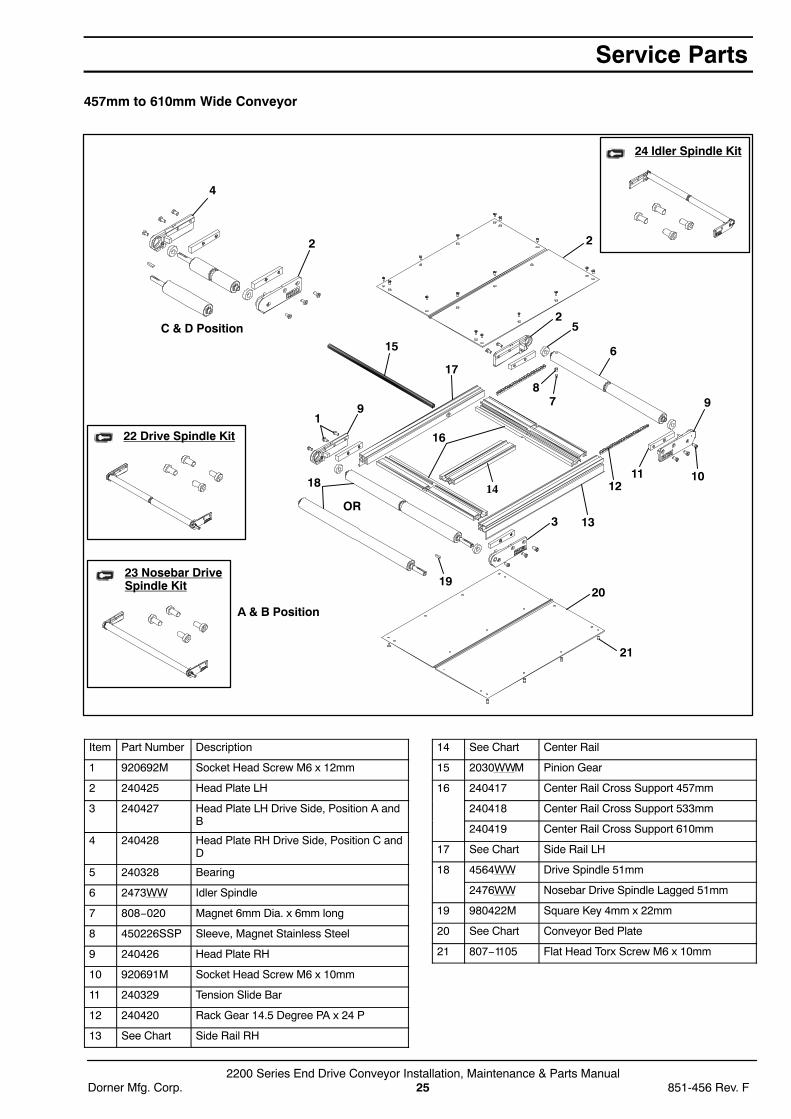
457mm to 610mm Wide Conveyor
22 Drive Spindle Kit
23 Nosebar DriveSpindle Kit
24 Idler Spindle Kit
C & D Position
A & B Position
2
6
4
18
16
19
14OR
3
20
13
21
1211 10
9
52
2
7
17
15
91
8
Item Part Number Description
1 920692M Socket Head Screw M6 x 12mm
2 240425 Head Plate LH
3 240427 Head Plate LH Drive Side, Position A andB
4 240428 Head Plate RH Drive Side, Position C andD
5 240328 Bearing
6 2473WW Idler Spindle
7 808−020 Magnet 6mm Dia. x 6mm long
8 450226SSP Sleeve, Magnet Stainless Steel
9 240426 Head Plate RH
10 920691M Socket Head Screw M6 x 10mm
11 240329 Tension Slide Bar
12 240420 Rack Gear 14.5 Degree PA x 24 P
13 See Chart Side Rail RH
14 See Chart Center Rail
15 2030WWM Pinion Gear
16 240417 Center Rail Cross Support 457mm
240418 Center Rail Cross Support 533mm
240419 Center Rail Cross Support 610mm
17 See Chart Side Rail LH
18 4564WW Drive Spindle 51mm
2476WW Nosebar Drive Spindle Lagged 51mm
19 980422M Square Key 4mm x 22mm
20 See Chart Conveyor Bed Plate
21 807−1105 Flat Head Torx Screw M6 x 10mm
Service Parts
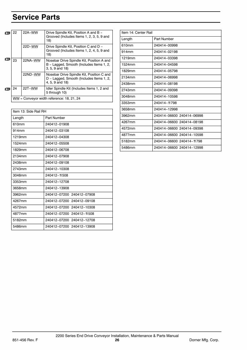
2200 Series End Drive Conveyor Installation, Maintenance & Parts Manual851-456 Rev. F 26 Dorner Mfg. Corp.
22 22A−WW Drive Spindle Kit, Position A and B −Grooved (Includes Items 1, 2, 3, 5, 9 and18)
22D−WW Drive Spindle Kit, Position C and D −Grooved (Includes Items 1, 2, 4, 5, 9 and18)
23 22NA−WW Nosebar Drive Spindle Kit, Position A andB − Lagged, Smooth (Includes Items 1, 2,3, 5, 9 and 18)
22ND−WW Nosebar Drive Spindle Kit, Position C andD − Lagged, Smooth (Includes Items 1, 2,4, 5, 9 and 18)
24 22T−WW Idler Spindle Kit (Includes Items 1, 2 and5 through 10)
WW = Conveyor width reference: 18, 21, 24
Item 13: Side Rail RH
Length Part Number
610mm 240412−01908
914mm 240412−03108
1219mm 240412−04308
1524mm 240412−05508
1829mm 240412−06708
2134mm 240412−07908
2438mm 240412−09108
2743mm 240412−10308
3048mm 240412−11508
3353mm 240412−12708
3658mm 240412−13908
3962mm 240412−07200 240412−07908
4267mm 240412−07200 240412−09108
4572mm 240412−07200 240412−10308
4877mm 240412−07200 240412−11508
5182mm 240412−07200 240412−12708
5486mm 240412−07200 240412−13908
Item 14: Center Rail
Length Part Number
610mm 240414−00998
914mm 240414−02198
1219mm 240414−03398
1524mm 240414−04598
1829mm 240414−05798
2134mm 240414−06998
2438mm 240414−08198
2743mm 240414−09398
3048mm 240414−10598
3353mm 240414−11798
3658mm 240414−12998
3962mm 240414−06600 240414−06998
4267mm 240414−06600 240414−08198
4572mm 240414−06600 240414−09398
4877mm 240414−06600 240414−10598
5182mm 240414−06600 240414−11798
5486mm 240414−06600 240414−12998
Service Parts

2200 Series End Drive Conveyor Installation, Maintenance & Parts ManualDorner Mfg. Corp. 27 851-456 Rev. F
Item 16: Side Rail LH
Length Part Number
610mm 240413−01908
914mm 240413−03108
1219mm 240413−04308
1524mm 240413−05508
1829mm 240413−06708
2134mm 240413−07908
2438mm 240413−09108
2743mm 240413−10308
3048mm 240413−11508
3353mm 240413−12708
3658mm 240413−13908
3962mm 240413−07200 240413−07908
4267mm 240413−07200 240413−09108
4572mm 240413−07200 240413−10308
4877mm 240413−07200 240413−11508
5182mm 240413−07200 240413−12708
5486mm 240413−07200 240413−13908
Item 17: Bed Plate
Length Part Number
610mm 2405WW−01900
914mm 2405WW−03100
1219mm 2405WW−04300
1524mm 2405WW−05500
1829mm 2405WW−06700
2134mm 2405WW−07900
2438mm 2405WW−09100
2743mm 2405WW−10300
3048mm 2405WW−11500
3353mm 2405WW−12700
3658mm 2405WW−13900
3962mm 2405WW−07196 2405WW−07900
4267mm 2405WW−07196 2405WW−09100
4572mm 2405WW−07196 2405WW−10300
4877mm 2405WW−07196 2405WW−11500
5182mm 2405WW−07196 2405WW−12700
5486mm 2405WW−07196 2405WW−13900
WW = Conveyor Width reference: 18, 21, 24
Service Parts
2200 Series End Drive Conveyor Installation, Maintenance & Parts Manual851-456 Rev. F 28 Dorner Mfg. Corp.
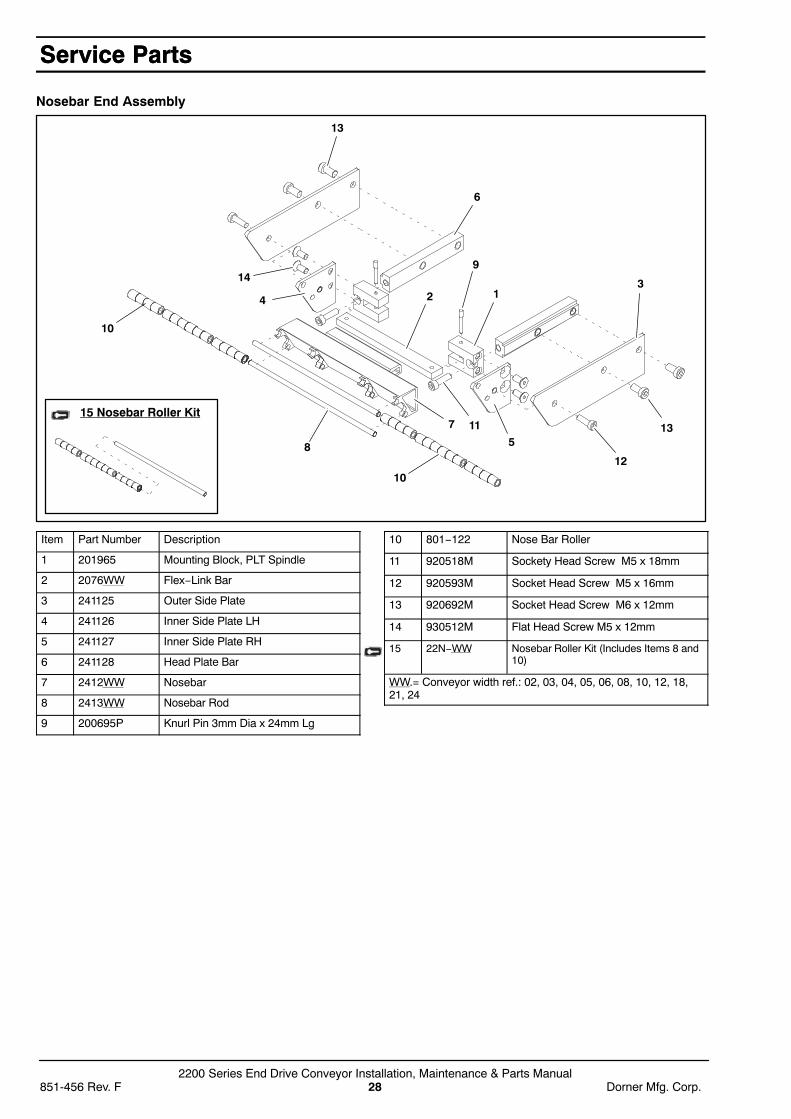
Nosebar End Assembly
14
13
12
11
10
5
32 1
9
8
6
4
7
10
1315 Nosebar Roller Kit
Item Part Number Description
1 201965 Mounting Block, PLT Spindle
2 2076WW Flex−Link Bar
3 241125 Outer Side Plate
4 241126 Inner Side Plate LH
5 241127 Inner Side Plate RH
6 241128 Head Plate Bar
7 2412WW Nosebar
8 2413WW Nosebar Rod
9 200695P Knurl Pin 3mm Dia x 24mm Lg
10 801−122 Nose Bar Roller
11 920518M Sockety Head Screw M5 x 18mm
12 920593M Socket Head Screw M5 x 16mm
13 920692M Socket Head Screw M6 x 12mm
14 930512M Flat Head Screw M5 x 12mm
15 22N−WW Nosebar Roller Kit (Includes Items 8 and10)
WW.= Conveyor width ref.: 02, 03, 04, 05, 06, 08, 10, 12, 18,21, 24
Service PartsService Parts
2200 Series End Drive Conveyor Installation, Maintenance & Parts ManualDorner Mfg. Corp. 29 851-456 Rev. F
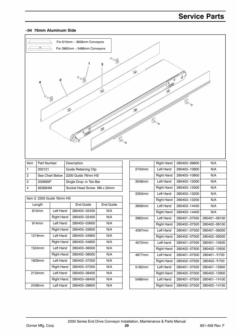
−04 76mm Aluminum Side
2
1
4
3
For 610mm − 3658mm Conveyors
For 3962mm − 5486mm Conveyors
Item Part Number Description
1 200121 Guide Retaining Clip
2 See Chart Below 2200 Guide 76mm HS
3 200695P Single Drop−in Tee Bar
4 920694M Socket Head Screw M6 x 20mm
Item 2: 2200 Guide 76mm HS
Length End Guide End Guide
610mm Left Hand 280403−02400 N/A
Right Hand 280403−02400 N/A
914mm Left Hand 280403−03600 N/A
Right Hand 280403−03600 N/A
1219mm Left Hand 280403−04800 N/A
Right Hand 280403−04800 N/A
1524mm Left Hand 280403−06000 N/A
Right Hand 280403−06000 N/A
1829mm Left Hand 280403−07200 N/A
Right Hand 280403−07200 N/A
2134mm Left Hand 280403−08400 N/A
Right Hand 280403−08400 N/A
2438mm Left Hand 280403−09600 N/A
Right Hand 280403−09600 N/A
2743mm Left Hand 280403−10800 N/A
Right Hand 280403−10800 N/A
3048mm Left Hand 280403−12000 N/A
Right Hand 280403−12000 N/A
3353mm Left Hand 280403−13200 N/A
Right Hand 280403−13200 N/A
3658mm Left Hand 280403−14400 N/A
Right Hand 280403−14400 N/A
3962mm Left Hand 280401−07500 280401−08100
Right Hand 280402−07500 280402−08100
4267mm Left Hand 280401−07500 280401−09300
Right Hand 280402−07500 280402−09300
4572mm Left hand 280401−07500 280401−10500
Right Hand 280402−07500 280402−10500
4877mm Left Hand 280401−07500 280401−11700
Right Hand 280402−07500 280402−11700
5182mm Left Hand 280401−07500 280401−12900
Right Hand 280402−07500 280402−12900
5486mm Left Hand 280401−07500 280401−14100
Right Hand 280402−07500 280402−14100
Service Parts

2200 Series End Drive Conveyor Installation, Maintenance & Parts Manual851-456 Rev. F 30 Dorner Mfg. Corp.
−05 38mm Aluminum Side
3
21
4
For 640mm − 3658mm Conveyors
For 3962mm − 5486mm Conveyors
Item Part Number Description
1 200121 Guide Retaining Clip
2 See Chart Below 2200 Guide 13mm HS
3 639971M Single Drop−in Tee Bar
4 920694M Socket Head Screw M6 x 20mm
Item 2: 2200 Guide 13mm HS
Length End Guide End Guide
610mm Left Hand 280503−02400 N/A
Right Hand 280503−02400 N/A
914mm Left Hand 280503−03600 N/A
Right Hand 280503−03600 N/A
1219mm Left Hand 280503−04800 N/A
Right Hand 280503−04800 N/A
1524mm Left Hand 280503−06000 N/A
Right Hand 280503−06000 N/A
1829mm Left Hand 280503−07200 N/A
Right Hand 280503−07200 N/A
2134mm Left Hand 280503−08400 N/A
Right Hand 280503−08400 N/A
2438mm Left Hand 280503−09600 N/A
Right Hand 280503−09600 N/A
2743mm Left Hand 280503−10800 N/A
Right Hand 280503−10800 N/A
3048mm Left Hand 280503−12000 N/A
Right Hand 280503−12000 N/A
3353mm Left Hand 280503−13200 N/A
Right Hand 280503−13200 N/A
3658mm Left Hand 280503−14400 N/A
Right Hand 280503−14400 N/A
3962mm Left Hand 280501−07500 280501−08100
Right Hand 280502−07500 280502−08100
4267mm Left Hand 280501−07500 280501−09300
Right Hand 280502−07500 280502−09300
4572mm Left hand 280501−07500 280501−10500
Right Hand 280502−07500 280502−10500
4877mm Left Hand 280501−07500 280501−11700
Right Hand 280502−07500 280502−11700
5182mm Left Hand 280501−07500 280501−12900
Right Hand 280502−07500 280502−12900
5486mm Left Hand 280501−07500 280501−14100
Right Hand 280502−07500 280502−14100
Service Parts
2200 Series End Drive Conveyor Installation, Maintenance & Parts ManualDorner Mfg. Corp. 31 851-456 Rev. F
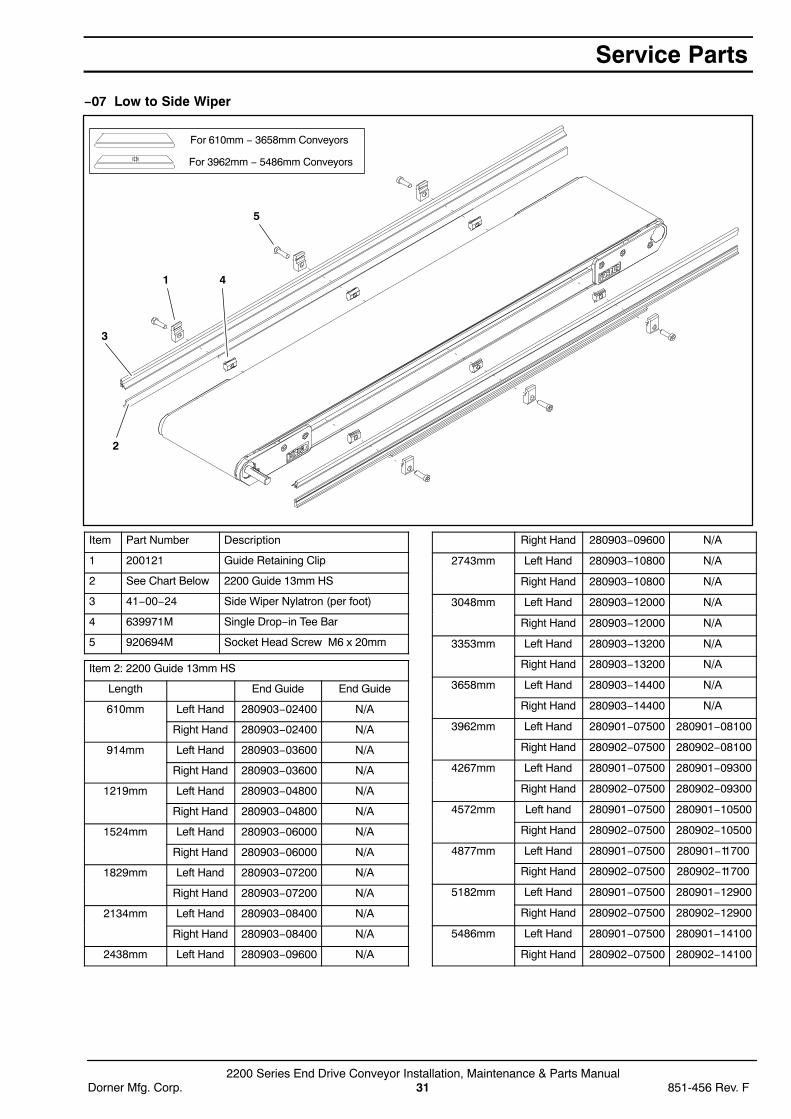
−07 Low to Side Wiper
5
1
2
3
4
For 610mm − 3658mm Conveyors
For 3962mm − 5486mm Conveyors
Item Part Number Description
1 200121 Guide Retaining Clip
2 See Chart Below 2200 Guide 13mm HS
3 41−00−24 Side Wiper Nylatron (per foot)
4 639971M Single Drop−in Tee Bar
5 920694M Socket Head Screw M6 x 20mm
Item 2: 2200 Guide 13mm HS
Length End Guide End Guide
610mm Left Hand 280903−02400 N/A
Right Hand 280903−02400 N/A
914mm Left Hand 280903−03600 N/A
Right Hand 280903−03600 N/A
1219mm Left Hand 280903−04800 N/A
Right Hand 280903−04800 N/A
1524mm Left Hand 280903−06000 N/A
Right Hand 280903−06000 N/A
1829mm Left Hand 280903−07200 N/A
Right Hand 280903−07200 N/A
2134mm Left Hand 280903−08400 N/A
Right Hand 280903−08400 N/A
2438mm Left Hand 280903−09600 N/A
Right Hand 280903−09600 N/A
2743mm Left Hand 280903−10800 N/A
Right Hand 280903−10800 N/A
3048mm Left Hand 280903−12000 N/A
Right Hand 280903−12000 N/A
3353mm Left Hand 280903−13200 N/A
Right Hand 280903−13200 N/A
3658mm Left Hand 280903−14400 N/A
Right Hand 280903−14400 N/A
3962mm Left Hand 280901−07500 280901−08100
Right Hand 280902−07500 280902−08100
4267mm Left Hand 280901−07500 280901−09300
Right Hand 280902−07500 280902−09300
4572mm Left hand 280901−07500 280901−10500
Right Hand 280902−07500 280902−10500
4877mm Left Hand 280901−07500 280901−11700
Right Hand 280902−07500 280902−11700
5182mm Left Hand 280901−07500 280901−12900
Right Hand 280902−07500 280902−12900
5486mm Left Hand 280901−07500 280901−14100
Right Hand 280902−07500 280902−14100
Service Parts
2200 Series End Drive Conveyor Installation, Maintenance & Parts Manual851-456 Rev. F 32 Dorner Mfg. Corp.
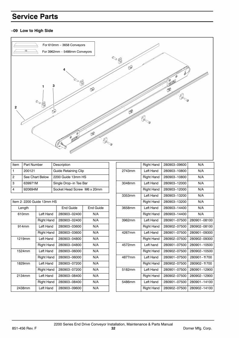
−09 Low to High Side
1
2
3
4
For 610mm − 3658 Conveyors
For 3962mm − 5486mm Conveyors
Item Part Number Description
1 200121 Guide Retaining Clip
2 See Chart Below 2200 Guide 13mm HS
3 639971M Single Drop−in Tee Bar
4 920694M Socket Head Screw M6 x 20mm
Item 2: 2200 Guide 13mm HS
Length End Guide End Guide
610mm Left Hand 280903−02400 N/A
Right Hand 280903−02400 N/A
914mm Left Hand 280903−03600 N/A
Right Hand 280903−03600 N/A
1219mm Left Hand 280903−04800 N/A
Right Hand 280903−04800 N/A
1524mm Left Hand 280903−06000 N/A
Right Hand 280903−06000 N/A
1829mm Left Hand 280903−07200 N/A
Right Hand 280903−07200 N/A
2134mm Left Hand 280903−08400 N/A
Right Hand 280903−08400 N/A
2438mm Left Hand 280903−09600 N/A
Right Hand 280903−09600 N/A
2743mm Left Hand 280903−10800 N/A
Right Hand 280903−10800 N/A
3048mm Left Hand 280903−12000 N/A
Right Hand 280903−12000 N/A
3353mm Left Hand 280903−13200 N/A
Right Hand 280903−13200 N/A
3658mm Left Hand 280903−14400 N/A
Right Hand 280903−14400 N/A
3962mm Left Hand 280901−07500 280901−08100
Right Hand 280902−07500 280902−08100
4267mm Left Hand 280901−07500 280901−09300
Right Hand 280902−07500 280902−09300
4572mm Left hand 280901−07500 280901−10500
Right Hand 280902−07500 280902−10500
4877mm Left Hand 280901−07500 280901−11700
Right Hand 280902−07500 280902−11700
5182mm Left Hand 280901−07500 280901−12900
Right Hand 280902−07500 280902−12900
5486mm Left Hand 280901−07500 280901−14100
Right Hand 280902−07500 280902−14100
Service Parts

2200 Series End Drive Conveyor Installation, Maintenance & Parts ManualDorner Mfg. Corp. 33 851-456 Rev. F
−10 13mm Extruded Plastic
3
2
1 4
5
For 607mm − 3658mm Conveyors
For 3962mm − 5486mm Conveyors
Item Part Number Description
1 200121 Guide Retaining Clip
2 200054P Snap−On Guide (per foot)
3 See Chart Below 2200 Guide
4 639971M Single Drop−in Tee Bar
5 920694M Socket Head Screw M6 x 20mm
Item 3: 2200 Guide
Length End Guide End Guide
610mm Left Hand 281003−02400 N/A
Right Hand 281003−02400 N/A
914mm Left Hand 281003−03600 N/A
Right Hand 281003−03600 N/A
1219mm Left Hand 281003−04800 N/A
Right Hand 281003−04800 N/A
1524mm Left Hand 281003−06000 N/A
Right Hand 281003−06000 N/A
1829mm Left Hand 281003−07200 N/A
Right Hand 281003−07200 N/A
2134mm Left Hand 281003−08400 N/A
Right Hand 281003−08400 N/A
2438mm Left Hand 281003−09600 N/A
Right Hand 281003−09600 N/A
2743mm Left Hand 281003−10800 N/A
Right Hand 281003−10800 N/A
3048mm Left Hand 281003−12000 N/A
Right Hand 281003−12000 N/A
3353mm Left Hand 281003−13200 N/A
Right Hand 281003−13200 N/A
3658mm Left Hand 281003−14400 N/A
Right Hand 281003−14400 N/A
3962mm Left Hand 281001−07500 281001−08100
Right Hand 281002−07500 281002−08100
4267mm Left Hand 281001−07500 281001−09300
Right Hand 281002−07500 281002−09300
4572mm Left hand 281001−07500 281001−10500
Right Hand 281002−07500 281002−10500
4877mm Left Hand 281001−07500 281001−11700
Right Hand 281002−07500 281002−11700
5182mm Left Hand 281001−07500 281001−12900
Right Hand 281002−07500 281002−12900
5486mm Left Hand 281001−07500 281001−14100
Right Hand 281002−07500 281002−14100
Service Parts

2200 Series End Drive Conveyor Installation, Maintenance & Parts Manual851-456 Rev. F 34 Dorner Mfg. Corp.
−13 Adjustable Guiding
1
98
5 4
3
2
7
11
6
10
Item Part Number Description
1 202983 Aluminum Profile Guide 610mm
202984 Aluminum Profile Guide 914mm
202985 Aluminum Profile Guide 1219mm
202986 Aluminum Profile Guide 1524mm
202987 Aluminum Profile Guide 1829mm
202988 Aluminum Profile Guide 2134mm
202989 Aluminum Profile Guide 2438mm
202990 Aluminum Profile Guide 2743mm
202991 Aluminum Profile Guide 3048mm
202992 Aluminum Profile Guide 3353mm
202993 Aluminum Profile Guide 3658mm
202994 Aluminum Profile Guide 3962mm
2 200830M Drop−In Tee Bar
3 202004 Mounting Bracket
4 202027M Guide Mounting Shaft Vertical
5 202028M Guide Moutning Shaft Horizontal
6 674175MP Square Nut
7 807−652 Cross Block
8 807−948 Vinyl Shaft Cap
9 614068P Flat Extruded Guide (per foot)
10 920612M Socket Head Screw M6 x 12mm
11 920616M Socket Head Screw M6 x 16mm
Service Parts

2200 Series End Drive Conveyor Installation, Maintenance & Parts ManualDorner Mfg. Corp. 35 851-456 Rev. F
13mm Cleated Belt Guiding
14
2
3
For 310mm − 3658 Conveyors
For 3962mm − 5486mm Conveyors
Item Part Number Description
1 200121 Guide Retaining Clip
2 See Chart Below 2200 Guide 13mm Cleated
3 639971M Drop−In Tee Bar
4 920694M Socket Head Screw M6 x 20mm
Item 2: 2200 Guide
Length End Guide End Guide
610mm Left Hand 281603−02256 N/A
Right Hand 281603−02256 N/A
914mm Left Hand 281603−03456 N/A
Right Hand 281603−03456 N/A
1219mm Left Hand 281603−04656 N/A
Right Hand 281603−04656 N/A
1524mm Left Hand 281603−05856 N/A
Right Hand 281603−05856 N/A
1829mm Left Hand 281603−07056 N/A
Right Hand 281603−07056 N/A
2134mm Left Hand 281603−08256 N/A
Right Hand 281603−08256 N/A
2438mm Left Hand 281603−09456 N/A
Right Hand 281603−09456 N/A
2743mm Left Hand 281603−10656 N/A
Right Hand 281603−10656 N/A
3048mm Left Hand 281603−11856 N/A
Right Hand 281603−11856 N/A
3353mm Left Hand 281603−13056 N/A
Right Hand 281603−13056 N/A
3658mm Left Hand 281603−14256 N/A
Right Hand 281603−14256 N/A
3962mm Left Hand 281601−07428 281601−08028
Right Hand 281602−07428 281602−08028
4267mm Left Hand 281601−07428 281601−09228
Right Hand 281602−07428 281602−09228
4572mm Left hand 281601−07428 281601−10428
Right Hand 281602−07428 281602−10428
4877mm Left Hand 281601−07428 281601−11628
Right Hand 281602−07428 281602−11628
5182mm Left Hand 281601−07428 281601−12828
Right Hand 281602−07428 281602−12828
5486mm Left Hand 281601−07428 281601−14028
Right Hand 281602−07428 281602−14028
Service Parts

2200 Series End Drive Conveyor Installation, Maintenance & Parts Manual851-456 Rev. F 36 Dorner Mfg. Corp.
25mm Cleated Belt Guiding
1
2
34
For 610mm − 3658mm Conveyors
For 3962mm − 5486mm Conveyors
Item Part Number Description
1 200121 Guide Retaining Clip
2 See Chart Below 2200 Guide 25mm Cleated
3 639971M Drop−In Tee Bar
4 920694M Socket Head Screw M6 x 20mm
Item 2: 2200 Guide
Length End Guide End Guide
610mm Left Hand 281703−02256 N/A
Right Hand 281703−02256 N/A
914mm Left Hand 281703−03456 N/A
Right Hand 281703−03456 N/A
1219mm Left Hand 281703−04656 N/A
Right Hand 281703−04656 N/A
1524mm Left Hand 281703−05856 N/A
Right Hand 281703−05856 N/A
1829mm Left Hand 281703−07056 N/A
Right Hand 281703−07056 N/A
2134mm Left Hand 281703−08256 N/A
Right Hand 281703−08256 N/A
2438mm Left Hand 281703−09456 N/A
Right Hand 281703−09456 N/A
2743mm Left Hand 281703−10656 N/A
Right Hand 281703−10656 N/A
3048mm Left Hand 281703−11856 N/A
Right Hand 281703−11856 N/A
3353mm Left Hand 281703−13056 N/A
Right Hand 281703−13056 N/A
3658mm Left Hand 281703−14256 N/A
Right Hand 281703−14256 N/A
3962mm Left Hand 281701−07428 281701−08028
Right Hand 281702−07428 281702−08028
4267mm Left Hand 281701−07428 281701−09228
Right Hand 281702−07428 281702−09228
4572mm Left hand 281701−07428 281701−10428
Right Hand 281702−07428 281702−10428
4877mm Left Hand 281701−07428 281701−11628
Right Hand 281702−07428 281702−11628
5182mm Left Hand 281701−07428 281701−12828
Right Hand 281702−07428 281702−12828
5486mm Left Hand 281701−07428 281701−14028
Right Hand 281702−07428 281702−14028
Service Parts

2200 Series End Drive Conveyor Installation, Maintenance & Parts ManualDorner Mfg. Corp. 37 851-456 Rev. F
51mm Cleated Belt Guiding
1
2
43
For 610mm − 3658mm Conveyors
For 3962mm − 5486mm Conveyors
Item Part Number Description
1 200121 Guide Retaining Clip
2 See Chart Below 2200 Guide 58mm Cleated
3 639971M Drop−In Tee Bar
4 920694M Socket Head Screw M6 x 20mm
Item 2: 2200 Guide
Length End Guide End Guide
610mm Left Hand 281903−02256 N/A
Right Hand 281903−02256 N/A
914mm Left Hand 281903−03456 N/A
Right Hand 281903−03456 N/A
1219mm Left Hand 281903−04656 N/A
Right Hand 281903−04656 N/A
1524mm Left Hand 281903−05856 N/A
Right Hand 281903−05856 N/A
1829mm Left Hand 281903−07056 N/A
Right Hand 281903−07056 N/A
2134mm Left Hand 281903−08256 N/A
Right Hand 281903−08256 N/A
2438mm Left Hand 281903−09456 N/A
Right Hand 281903−09456 N/A
2743mm Left Hand 281903−10656 N/A
Right Hand 281903−10656 N/A
3048mm Left Hand 281903−11856 N/A
Right Hand 281903−11856 N/A
3353mm Left Hand 281903−13056 N/A
Right Hand 281903−13056 N/A
3658mm Left Hand 281903−14256 N/A
Right Hand 281903−14256 N/A
3962mm Left Hand 281901−07428 281901−08028
Right Hand 281902−07428 281902−08028
4267mm Left Hand 281901−07428 281901−09228
Right Hand 281902−07428 281902−09228
4572mm Left hand 281901−07428 281901−10428
Right Hand 281902−07428 281902−10428
4877mm Left Hand 281901−07428 281901−11628
Right Hand 281902−07428 281902−11628
5182mm Left Hand 281901−07428 281901−12828
Right Hand 281902−07428 281902−12828
5486mm Left Hand 281901−07428 281901−14028
Right Hand 281902−07428 281902−14028
Service Parts
2200 Series End Drive Conveyor Installation, Maintenance & Parts Manual851-456 Rev. F 38 Dorner Mfg. Corp.
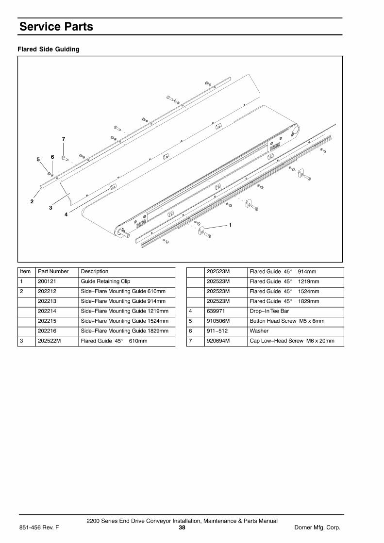
Flared Side Guiding
1
4
6
3
5
7
2
Item Part Number Description
1 200121 Guide Retaining Clip
2 202212 Side−Flare Mounting Guide 610mm
202213 Side−Flare Mounting Guide 914mm
202214 Side−Flare Mounting Guide 1219mm
202215 Side−Flare Mounting Guide 1524mm
202216 Side−Flare Mounting Guide 1829mm
3 202522M Flared Guide 45� 610mm
202523M Flared Guide 45� 914mm
202523M Flared Guide 45� 1219mm
202523M Flared Guide 45� 1524mm
202523M Flared Guide 45� 1829mm
4 639971 Drop−In Tee Bar
5 910506M Button Head Screw M5 x 6mm
6 911−512 Washer
7 920694M Cap Low−Head Screw M6 x 20mm
Service Parts

2200 Series End Drive Conveyor Installation, Maintenance & Parts ManualDorner Mfg. Corp. 39 851-456 Rev. F
Flat Belt Stand Mount Assembly
1
6
5
3
2
4
7
Item Part Number Description
1 240831 Stand Mount
2 300150M Drop−In Tee Bar
3 605279P Washer
4 807−920 Square Nut M6
5 920620M Socket Head Screw M6 x 20mm
6 920692M Socket Low Head Screw M6x12mm
7 240839 Flat Belt Stand Mount Assembly
Cleated Belt Stand Mount Assembly
1
6
5 3
2
4
7
Item Part Number Description
1 240836 Cleated Mount Assembly
2 300150M Drop−In Tee Bar
3 605279P Washer
4 807−920 Square Nut M6
5 920620M Socket Head Screw M6 x 20mm
6 920692M Socket Low Head Screw M6x12mm
7 240838 Cleated Stand Mount Assembly
Service Parts

2200 Series End Drive Conveyor Installation, Maintenance & Parts Manual851-456 Rev. F 40 Dorner Mfg. Corp.
Flat Belt Stand Mount Assembly for 610mm Conveyors
1
7
6 3
2
4
5
8
Item Part Number Description
1 240833 Stand Mount, LH 610mm
2 240834 Stand Mount, RH 610mm
3 605279P Washer
4 639971M Drop−In Tee Bar
5 807−920 Square Nut M6
6 920620M Socket Head Screw M6 x 20mm
7 920692M Socket Low Head Screw M6x12mm
8 240847 Flat Belt Stand Mount Assembly for610mm Conveyors
Cleated Belt Stand Mount Assembly for 610mm Conveyors
1
7
6 32
4
5
8
Item Part Number Description
1 240852 Cleated Stand Bracket Assembly LH610mm Conveyor
2 240853 Cleated Stand Bracket Assembly RH610mm Conveyor
3 605279P Washer
4 639971M Drop−In Tee Bar
5 807−920 Square Nut M6
6 920620M Socket Head Screw M6 x 20mm
7 920692M Socket Low Head Screw M6x12mm
8 240851 Cleated Belt Stand Mount Assembly for610mm Conveyors
Service Parts
2200 Series End Drive Conveyor Installation, Maintenance & Parts ManualDorner Mfg. Corp. 41 851-456 Rev. F
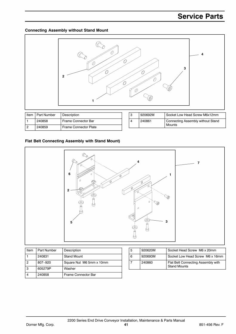
Connecting Assembly without Stand Mount
3
2
1
4
Item Part Number Description
1 240858 Frame Connector Bar
2 240859 Frame Connector Plate
3 920692M Socket Low Head Screw M6x12mm
4 240861 Connecting Assembly without StandMounts
Flat Belt Connecting Assembly with Stand Mount)
16
5 3
2
4 7
Item Part Number Description
1 240831 Stand Mount
2 807−920 Square Nut M6 5mm x 10mm
3 605279P Washer
4 240858 Frame Connector Bar
5 920620M Socket Head Screw M6 x 20mm
6 920693M Socket Low Head Screw M6 x 16mm
7 240860 Flat Belt Connecting Assembly withStand Mounts
Service Parts

2200 Series End Drive Conveyor Installation, Maintenance & Parts Manual851-456 Rev. F 42 Dorner Mfg. Corp.
Cleated Belt Connecting Assembly with Stand Mount
1
6
5 3
2
4
7
Item Part Number Description
1 240836 Cleated Stand Bracket
2 807−920 Square Nut M6 5mm x 10mm
3 605279P Washer
4 240858 Frame Connector Bar
5 920620M Socket Head Screw M6 x 20mm
6 920693M Socket Low Head Screw M6 x 16mm
7 240863 Cleated Belt Connecting Assemblywith Stand Mounts
51mm to 152mm Flat Belt Return Roller
2
5
4
31
7
6
Item Part Number Description
1 240825 Return Roller Guard − Short
2 240827 Return Roller Clip
3 802−027 Bearing
4 913−100 Dowel Pin
5 920693M Socket Low Head Screw M6 x 16mm
6 240840 Roller Assembly (Includes Items 1, 3and 4)
7 240830 51mm to 152mm Flat Belt ReturnRoller Assy
Service Parts
2200 Series End Drive Conveyor Installation, Maintenance & Parts ManualDorner Mfg. Corp. 43 851-456 Rev. F
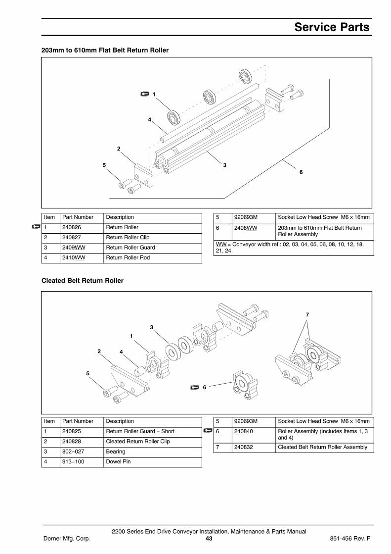
203mm to 610mm Flat Belt Return Roller
5
1
2
3
4
6
Item Part Number Description
1 240826 Return Roller
2 240827 Return Roller Clip
3 2409WW Return Roller Guard
4 2410WW Return Roller Rod
5 920693M Socket Low Head Screw M6 x 16mm
6 2408WW 203mm to 610mm Flat Belt ReturnRoller Assembly
WW.= Conveyor width ref.: 02, 03, 04, 05, 06, 08, 10, 12, 18,21, 24
Cleated Belt Return Roller
5
2 4
1
3
7
6
Item Part Number Description
1 240825 Return Roller Guard − Short
2 240828 Cleated Return Roller Clip
3 802−027 Bearing
4 913−100 Dowel Pin
5 920693M Socket Low Head Screw M6 x 16mm
6 240840 Roller Assembly (Includes Items 1, 3and 4)
7 240832 Cleated Belt Return Roller Assembly
Service Parts
2200 Series End Drive Conveyor Installation, Maintenance & Parts Manual851-456 Rev. F 44 Dorner Mfg. Corp.
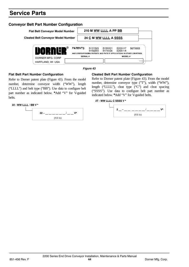
Conveyor Belt Part Number Configuration
Figure 43
Flat Belt Conveyor Model Number 210 M WW LLLL A PP BB
Cleated Belt Conveyor Model Number 24 C M WW LLLL A SSSS
DORNER MFG. CORP
HARTLAND, WI USA
SERIAL # MODEL #
Flat Belt Part Number Configuration
Refer to Dorner patent plate (Figure 43). From the modelnumber, determine conveyor width (“WW”), length(“LLLL”) and belt type (“BB”). Use data to configure beltpart number as indicated below. *Add “V” for V-guidedbelts.
22 - WW LLLL / BB V *
22 − __ __ __ __ __ __ / __ __ V*
(Fill In)
Cleated Belt Part Number ConfigurationRefer to Dorner patent plate (Figure 43). From the modelnumber, determine conveyor type (”T”), width (“WW”),length (“LLLL”), cleat type (“C”) and cleat spacing(“SSSS”). Use data to configure belt part number asindicated below. *Add “V” for V-guided belts.
(Fill In)
2T - WW LLLL C SSSS V *
2 __ − __ __ __ __ __ __ / __ __ __ __ V*
Service Parts

2200 Series End Drive Conveyor Installation, Maintenance & Parts ManualDorner Mfg. Corp. 45 851-456 Rev. F
Notes
No returns will be accepted without prior written factory authorization. When calling for authorization, pleasehave the following information ready for the Dorner Factory representative or your local distributor:
1. Name and address of customer.
2. Item(s) being returned.
3. Reason for return.
4. Customer’s original order number used when ordering the item(s).
5. Dorner or distributor invoice number.
A representative will discuss action to be taken on the Returned items and provide a Returned GoodsAuthorization Number to reference.
There will be a 15% restocking charge on all new items returned for credit where Dorner was not at fault. Thesewill not be accepted after 60 days from original invoice date. The restocking charge covers inspection, cleaning,disassembly, and reissuing to inventory.If a replacement is needed prior to evaluation of returned item, a purchase order must be issued. Credit(if any) is issued only after return and evaluation is complete.
Dorner has representatives throughout the world. Feel free to contact Dorner for the name of your local representative.Our technical sales and service staff will gladly help with your questions on Dorner products.
For a copy of Dorner’s Limited Warranty, contact factory, distributor, service center or visit our website atwww.dorner.com.
851-456 Rev. F Printed in U.S.A.
Dorner Mfg. Corp. reserves the right to change ordiscontinue products without notice. All products andservices are covered in accordance with our standardwarranty. All rights reserved. Dorner Mfg. Corp. 2000
For replacement parts, contact an authorizedDorner Service Center or the factory.
Return Policy
975 Cottonwood Drive, PO Box 20Hartland, WI 53029-0020 USAUSATEL 1-800-397-8664 (USA) FAX 1-800-369-2440 (USA)Internet: www.dorner.com
Outside the USA:TEL 1-262-367-7600FAX 1-262-367-5827
DORNER MFG. CORP.