Embed Size (px)
Citation preview

Page 1 of 12 04-21-09F-4123
2-7573
INSTALLATION MANUAL1585 LOADERS
L3130, L3430, L3830, & L4440 KUBOTA TRACTORS
ASSEMBLY MANUAL
Keep With Operator’s Manual
TRACTOR & LOADER GENERAL INFORMATION
Mounting kit can be installed using tools ordinarily available,including a hoist capable of lifting and supporting the loaderfor initial mounting, standard and metric wrenches, torquewrench, and hydraulic oil.
Tractor-supplied hydraulic power is required for loadermounting and operation.
The grille guard (3) may be installed with or without theloader. Refer to instructions on page 2.
Check tractor tire pressure. Refer to tractor operator'smanual for recommended pressures. With tractor on a firm,level surface, compare tractor rear axle height from left toright, measuring from axle center to ground. Adjust airpressure in rear tires until axle height measures same forboth sides.
NOTE: If rear axle on tractor is not level from side to side,cutting edge on loader bucket or similar loader- mountedattachments will not sit flat on ground.
Set the tractor’s Front Tread Width to 1055mm (41.5”) ona 2WD tractor to provide adequate clearance, the 4WD isnot adjustable. For better stability, set the rear tread to1020mm (40.2”).
Tractor steering stops may have to be adjusted to provideclearance between front tire and loader on full left and rightturn with front axle fully oscillated. Be sure lift cylindersare fully retracted when checking tire clearances. Refer totractor operator's manual for steering stop adjustment.
NOTE: Reference to left and right used in theseinstructions refer to position when seated in the operatingposition on tractor.
PREPARING TRACTOR
Shut off engine, engage brakes, and remove key duringinstallation. If tractor is equipped with front weights, removeweights and weight bracket.
Remove plastic thread protectors from holes on left andright sides of tractor clutch housing and front axle.
PALLET COMPONENT REMOVAL (Figure 1)
The loader boom, bucket, left and right mid mounts,hydraulic package, and grille guard come on one pallet.Remove plastic protective cover from pallet. Untie andremove grille guard from pallet. Support mid mountingbrackets and untie and remove from pallet. Removehydraulic box of parts from pallet. Support bucket thenremove hold downs and remove from pallet.
Figure 1 - Loader Shipping Example
IMPORTANT: Clean threaded holes in tractor chassisthoroughly using a tap of proper size. Paint, rust, or debrisin the threads may not permit cap screws to be installedand tightened correctly.
NOTE: Support mid mounting brackets when removingfrom shipping materials.
Warning: Loader must be supported beforeremoving hardware securing loader toshipping pallet or loader will tip over.
Support loader boom arms with lifting device and nylonstraps. Lift loader slightly to remove load from support postand remove it.

Page 2 of 12 04-21-09F-4123
2-7573
PALLET COMPONENT REMOVAL (CONTINUED)
Lower loader boom onto ground, positioning scraps ofcardboard on floor under loader to prevent loader paintdamage. Remove Pallet.
NOTE: Do not tighten hardware to full torque until themounting kit is completely assembled unless otherwisenoted. This will allow proper assembly and alignment ofparts as they are installed. Before finally tightening allmounting hardware, start the engine and apply downwardpressure to the loader bucket, removing the load from thefront tires (Do not lift tires off the ground!). Make sure themounting pins can be rotated easily.
INSTALLING GRILLE GUARD (Figure 3)
1. Position grille guard (3) on front of tractor.
2. Secure with HHCS M14x40mm (12) and M14lockwashers (11).
3. Torque bolts after all have been installed using GeneralTorque Specifications. (See page 12)
INSTALLING LEFT AND RIGHT MIDMOUNTINGBRACKETS (Figure 3)
1. Lift right mid mounting bracket (1) with overhead hoist.Fasten right mid mounting bracket (1) to tractor castingand front axle housing using HHCS M16x40mm (13)and M16 lockwashers (14).
2. Raise left mid mounting bracket (2) with overhead hoist.Fasten left mid mounting bracket (2) to tractor castingand front axle housing using HHCS M16x40mm (13)and M16 lockwashers (14).
PLUMBING HYDRAULIC VALVE
1. Install O-ring 90° elbow fittings in port on each side ofvalve pointing away from handle. Install O-ring 90°elbow fitting in front tank port pointing away fromjoystick. Tighten jam nuts.
2. Install straight O-ring to pipe adapters on front ports ofvalve. Install male quick couplers on male adapters onvalve. Attach color coded identification dust covers onquick couplers. Boom lift is on right and bucketfunctions are on left. (Figure 8)
ATTACHING VALVE AND VALVE BRACKET TOTRACTOR (Figure’s 2, 3, & 8)
1. Attach valve bracket (4) to tractor frame on the rightside inside of the mid mount using HHCS 10mm-1.5x40mm CL10.9ZP bolts (8), 10mm-1.5 PL10.9 nuts(10), and M10 lockwashers (9).
NOTE: Make sure there is adequate clearancebetween valve mounting bracket and the linkage thatruns behind it.
2. Attach valve (19) to valve bracket (4) using HHCS 8-P15-50mm PL10 bolts (5), M8 lockwashers (6), andM8 hex nuts (7). (See Figures 2, 3, & 8)
ATTACHING TRACTOR HYDRAULIC BLOCK
1. Remove cover from tractor hydraulic area locatedunder foot rest on right side of tractor. Alignattaching holes in tractor with holes in hydraulicblock. Install hydraulic block with O-rings in placeusing (4) bolts, Lockwashers (35mm for the L4440and 90mm for others) and O-rings. (2 ports are ontop and one port to lower front of tractor).
NOTE: The remaining bolts will be left after install
2. Install 90° pipe hydraulic elbow fitting in top frontpressure port and point the end toward front of
48856-2 - HEXB METRIC8 - P1.25 - 50MM PL10
G11501066 - M8 NUT
701511C - M8 LOCK WASHER
54070 - Bracket
Figure 2- Joystick and Valve Mounting
Page 3 of 12 04-21-09F-4123
2-7573
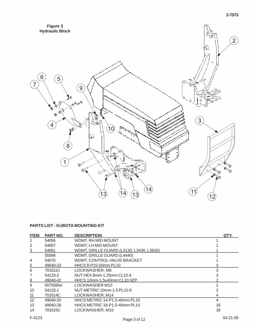
PARTS LIST - KUBOTA MOUNTING KIT
ITEM PART NO. DESCRIPTION QTY.1 54056 WDMT, RH MID MOUNT 12 54057 WDMT, LH MID MOUNT 13 54061 WDMT, GRILLE GUARD (L3130, L3430, L3830) 1
55598 WDMT, GRILLE GUARD (L4440) 14 54070 WDMT, CONTROL VALVE BRACKET 15 49040-23 HHCS 8-P15-50mm PL10 36 701611C LOCKWASHER, M8 37 54133-2 NUT HEX 8mm-1.25mm CL10.9 38 49040-42 HHCS 10mm-1.5x40mm CL10.9ZP 29 00755954 LOCKWASHER M10 210 54133-1 NUT METRIC 10mm-1.5 PL10.9 211 701614C LOCKWASHER, M14 412 49040-20 HHCS METRIC 14-P1.5-40mm PL10 413 49040-28 HHCS METRIC 16-P1.5-40mm PL10 1814 701615C LOCKWASHER, M16 18
2
1
3
121113 14 13
14
104
8
7
6
9
5
Figure 3Hydraulic Block

Page 4 of 12 04-21-09F-4123
2-7573
INSTALLING MANUAL CANISTER TO BOOMASSEMBLY
1. Use two 1/4” bolts, M8 lock washers, M8 plainwashers, and 1/4” nuts to attach canister to bracket.
2. Remove bolts (27) and washers (28 & 30) from cover(26).
3. Using bolts that were just removed, attach bracketand cover to boom assembly.
4. Insure manual is placed in the canister.
MOUNTING LOADER TO TRACTOR (Figures 5 & 6)
WARNING: To avoid injury, an overhead hoistmust be used for initial mounting, do notpermit bystanders within ten feet of loader.Parking stands are not operational withoutbucket or heavy attachment mounted. Balespear or pallet fork alone do not provideenough weight.
1. Secure a hoist strap around loader upper boom armsand slowly raise loader with overhead hoist until loaderuprights are slightly higher than mounts on the tractor.Make sure loader is centered with the tractor.
2. Start tractor, release brakes, and drive tractor forwarduntil mounts are touching. Engage brakes and shutoff tractor.
3. With overhead hoist, lower loader until loader uprightmounts are seated in saddle of tractor mounts.Connect hydraulic hoses to correct ports.
Figure 5Mount Location
tractor.
3. Install straight pipe adapters into other two ports.(Figure 8)
HOSE PLUMBING
1. Connect pressure hose from top front 90° elbow fittingon tractor hydraulic block to valve 90° elbow fitting leftinlet on valve. (P Port).
2. Connect tank hose with tube 90° bend from hydraulicblock lower front port (tank port) to 90° elbow fitting onfront of valve. (T Port).
3. Connect power beyond hose with tube 90° bend fromhydraulic block rear upper port (power beyond) to 90°elbow fitting on valve (on right side of valve). (Figure 4)
PLUMBING LOADER TO CONTROL VALVE (Figure 8)
1. Install hoses onto boom oil tubes. Install and tightenone at a time from the bottom up. Loosening the closestoil line clamp will ease installation.
2. Install large identification dust plugs onto free ends ofhoses. Slide Hose sleeve over hoses. Install femalequick couplers onto free ends of hoses.
3. Connect hoses from upper two boom oil lines to rightmale couplers on valve and the lower two boom oillines to left male quick couplers on valve, making sureto match the colors. (Figure 8)
4. Attach free end of rubber strap to loader right sideframe.
5. After all plumbing has been completed, slowly cyclelift and bucket cylinders several times to purge air fromhydraulic system. Retract cylinders and shut off tractorengine, engage parking brake, and remove key.Replenish tractor hydraulic system with recommendedhydraulic fluid.
Power Beyond Port
Pump Port
Tank Port
Figure 4- Joystick and Valve Mounting
Page 5 of 12 04-21-09F-4123
2-7573
Figure 6
MOUNTING LOADER TO TRACTOR (CONTINUED)
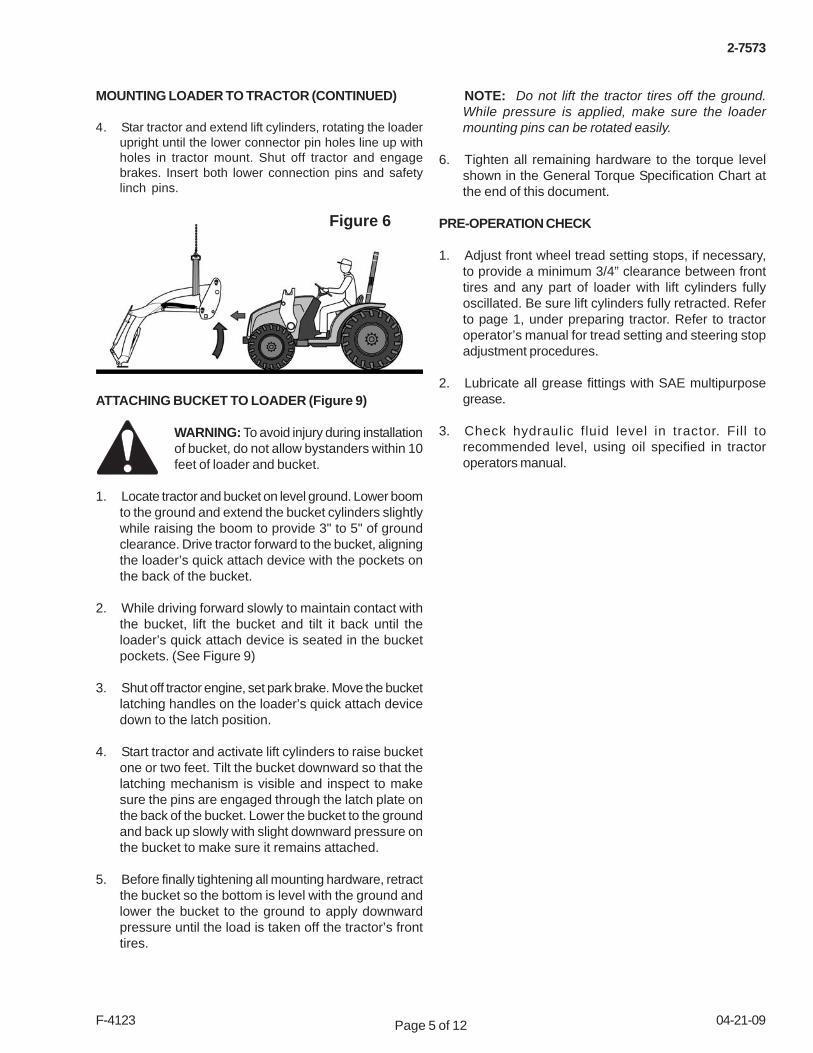
4. Star tractor and extend lift cylinders, rotating the loaderupright until the lower connector pin holes line up withholes in tractor mount. Shut off tractor and engagebrakes. Insert both lower connection pins and safetylinch pins.
ATTACHING BUCKET TO LOADER (Figure 9)
WARNING: To avoid injury during installationof bucket, do not allow bystanders within 10feet of loader and bucket.
1. Locate tractor and bucket on level ground. Lower boomto the ground and extend the bucket cylinders slightlywhile raising the boom to provide 3" to 5" of groundclearance. Drive tractor forward to the bucket, aligningthe loader’s quick attach device with the pockets onthe back of the bucket.
2. While driving forward slowly to maintain contact withthe bucket, lift the bucket and tilt it back until theloader’s quick attach device is seated in the bucketpockets. (See Figure 9)
3. Shut off tractor engine, set park brake. Move the bucketlatching handles on the loader’s quick attach devicedown to the latch position.
4. Start tractor and activate lift cylinders to raise bucketone or two feet. Tilt the bucket downward so that thelatching mechanism is visible and inspect to makesure the pins are engaged through the latch plate onthe back of the bucket. Lower the bucket to the groundand back up slowly with slight downward pressure onthe bucket to make sure it remains attached.
5. Before finally tightening all mounting hardware, retractthe bucket so the bottom is level with the ground andlower the bucket to the ground to apply downwardpressure until the load is taken off the tractor’s fronttires.
NOTE: Do not lift the tractor tires off the ground.While pressure is applied, make sure the loadermounting pins can be rotated easily.
6. Tighten all remaining hardware to the torque levelshown in the General Torque Specification Chart atthe end of this document.
PRE-OPERATION CHECK
1. Adjust front wheel tread setting stops, if necessary,to provide a minimum 3/4” clearance between fronttires and any part of loader with lift cylinders fullyoscillated. Be sure lift cylinders fully retracted. Referto page 1, under preparing tractor. Refer to tractoroperator’s manual for tread setting and steering stopadjustment procedures.
2. Lubricate all grease fittings with SAE multipurposegrease.
3. Check hydraulic fluid level in tractor. Fill torecommended level, using oil specified in tractoroperators manual.

Page 6 of 12 04-21-09F-4123
2-7573
PARTS LIST - LOADER
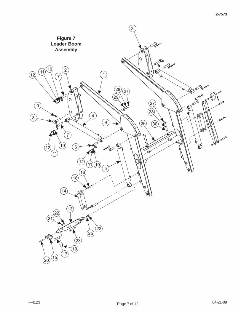
ITEM PART NO. DESCRIPTION QTY.1 54053 WDMT,LOADER BOOM 12 54054 WDMT,RH SIDE FRAME 13 54055 WDMT,LH SIDE FRAME 14 54094 ASY, HYDRAULIC BOOM CYLINDER 25 54096 ASY, HYDRAULIC BUCKET CYLINDER 26 54124 PIN 47 54125 PIN 48 54126 PIN-LEVER 29 54123 PIN, LINK 210 701512C FLATWASHER, M10 811 00755954 LOCKWASHER M10 812 49040-25 HHCS 10mm-P1.5- 20mm PL10 813 54063 STAND 214 54064 BRACKET, STAND 215 64065 BRACKET 216 54128 PIN 217 54129 PIN 218 54122 RING, SNAP 419 54127 PIN, R 220 49040-26 HHCS 12mm-P1.75-90mm PL10 221 701513C FLATWASHER, M12 222 54134-1 NUT,LK MET 12mm-1.75 PL10.9 223 49040-37 HHCS M20-P2.5x90mm PL10.9 224 2971157 FLATWASHER, 20mm 225 54134-3 NUT,LOCK MET 20mm-2.5 PL10.9 226 54186 COVER 127 49040-34 HHCS, 8mm-1.25mmx25 GR8 ZP 628 701611C LOCKWASHER, M8 629 54073 COVER 130 701511C FLATWASHER, M8 4
Page 7 of 12 04-21-09F-4123
2-7573
1
17
13
9
23
15
4
5
8
9
6
7
10
11
12
20
21
25
18
26
29
2728
30
14
28
27
1211 10
2
3
22
1211
10
7
16
22
19
Figure 7Loader Boom
Assembly
Page 8 of 12 04-21-09F-4123
2-7573
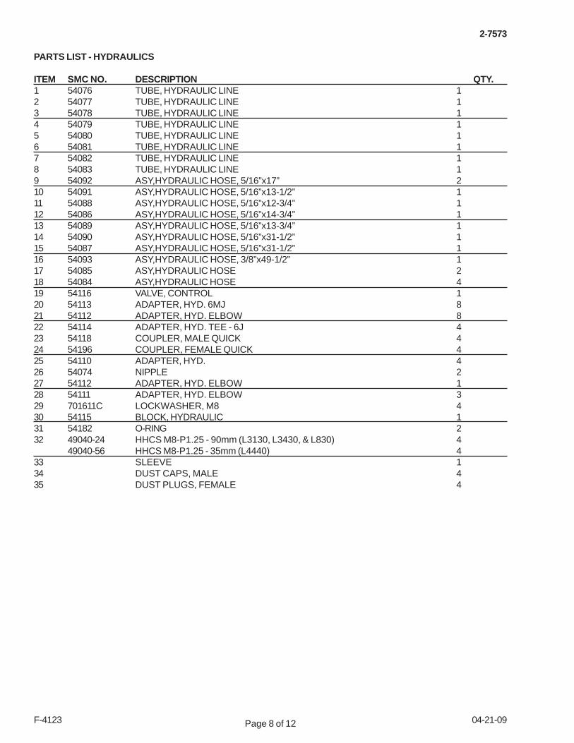
PARTS LIST - HYDRAULICS
ITEM SMC NO. DESCRIPTION QTY.1 54076 TUBE, HYDRAULIC LINE 12 54077 TUBE, HYDRAULIC LINE 13 54078 TUBE, HYDRAULIC LINE 14 54079 TUBE, HYDRAULIC LINE 15 54080 TUBE, HYDRAULIC LINE 16 54081 TUBE, HYDRAULIC LINE 17 54082 TUBE, HYDRAULIC LINE 18 54083 TUBE, HYDRAULIC LINE 19 54092 ASY,HYDRAULIC HOSE, 5/16”x17” 210 54091 ASY,HYDRAULIC HOSE, 5/16”x13-1/2” 111 54088 ASY,HYDRAULIC HOSE, 5/16”x12-3/4” 112 54086 ASY,HYDRAULIC HOSE, 5/16”x14-3/4” 113 54089 ASY,HYDRAULIC HOSE, 5/16”x13-3/4” 114 54090 ASY,HYDRAULIC HOSE, 5/16”x31-1/2” 115 54087 ASY,HYDRAULIC HOSE, 5/16”x31-1/2” 116 54093 ASY,HYDRAULIC HOSE, 3/8”x49-1/2” 117 54085 ASY,HYDRAULIC HOSE 218 54084 ASY,HYDRAULIC HOSE 419 54116 VALVE, CONTROL 120 54113 ADAPTER, HYD. 6MJ 821 54112 ADAPTER, HYD. ELBOW 822 54114 ADAPTER, HYD. TEE - 6J 423 54118 COUPLER, MALE QUICK 424 54196 COUPLER, FEMALE QUICK 425 54110 ADAPTER, HYD. 426 54074 NIPPLE 227 54112 ADAPTER, HYD. ELBOW 128 54111 ADAPTER, HYD. ELBOW 329 701611C LOCKWASHER, M8 430 54115 BLOCK, HYDRAULIC 131 54182 O-RING 232 49040-24 HHCS M8-P1.25 - 90mm (L3130, L3430, & L830) 4
49040-56 HHCS M8-P1.25 - 35mm (L4440) 433 SLEEVE 134 DUST CAPS, MALE 435 DUST PLUGS, FEMALE 4

Page 9 of 12 04-21-09F-4123
2-7573
“C”
5
1
2
3
4
6
7
8
21
10
11
12
33
14
9
16
18
17
29
32
22
20
“A & B”
“D & E”
20
9
15
30
31
17
Figure 8 - A, B, C, & DHydraulics
Tank Port
PowerBeyond Port
PumpPort
“E”
1. RED, 3/8” x 26” (Tilt Cylinder Rod end)2. BLUE, 3/8” x 26” (Tilt Cylinder Butt end)3. BLACK, 3/8” x 26” (Lift Cylinder Rod end)4. YELLOW, 3/8” x 26” (Lift Cylinder Butt end)
PumpPort
Tank Port
PowerBeyond Port
4
23
1
“B”
34
“A”8
7
65
RED
BLACK
YELLOW
BLUE
“C”
“D”
27
26
17
18“P/B”
“T” 25“P”
19
23
24
28
17

Page 10 of 12 04-21-09F-4123
2-7573
PARTS LIST - Coupler & Bucket
ITEM PART NO. DESCRIPTION QTY.1 54069 WDMT, COUPLER 12 54072 LEVER, LH QH 13 54071 LEVER, RH QH 14 54130 PIN, 30mm DIAx30mm L 25 54131 PIN, 30mm DIA 26 54132 PIN, 30mm DIA 27 54119 SPRING, 5mm DIA 28 54120 SPRING, 4.55mm DIA 29 54125 PIN 410 48856-4 HHCS 10mm-P1.5-20mm PL10 411 701512C FLATWASHER, M10 412 00755954 LOCKWASHER M10 413 701515C FLATWASHER, M16 214 54134-2 NUT, LOCK MET 16mm-2.0 PL10.9 615 54121 PIN, SPRING 216 54068 WDMT, BUCKET 1

Page 11 of 12 04-21-09F-4123
2-7573
Figure 9Bucket
and Coupler

Page 12 of 12 04-21-09F-4123
2-7573
PARTS LIST - Bondiolli Valve
ITEM PART NO. DESCRIPTION QTY.1 54618 SPOOL ASSEMBLY 12 54619 SPOOL CONTROL T17 13 54620 SPOOL CONTROL HOUSING 14 54621 SPOOL CONTROL N70 15 54622 SPOOL ASSEMBLY 16 54623 PLUG, M18-1.5 17 54624 PLUG, 3/4-16 18 54625 SLEEVE, POWER BEYOND 19 54574 KIT, JOYSTICK 110 54627 RELIEF VALVE, 170 bar 111 54628 CHECK VALVE 212 54630 RUBBER BOOT, JOYSTICK 113 54631 CABLE TIE 114 54617 LEVER, JOYSTICK 115 54629 SEAL KIT, VALVE 1

Page 13 of 12 04-21-09F-4123
2-7573
Figure 10BONDIOLLI VALVE

Page 14 of 12 04-21-09F-4123
2-7573
INSTALLATION INSTRUCTIONS
AMERICAN STANDARD CAP SCREWS METRIC CAP SCREWS
GENERAL TORQUE SPECIFICATIONSUSE THE FOLLOWING TORQUES WHEN SPECIAL TORQUES ARE NOT GIVEN
SAE GradeTyp. HeadMarkings
Metric ClassTyp. HeadMarkings
5 8 8.8 10.9
Cap Screw TORQUE
Assembly Torque
TORQUE TORQUE TORQUESize FT·LBS N·m FT·LBS N·m FT·LBS N·m FT·LBS N·m
Inches MIN MAX MIN MAX MIN MAX MIN MAX6.25 7.25 8.5 10 8.25 9.5 11 13
8 9 11 12 10.5 12 14 1614 15 19 20 18.5 20 25 27
17.5 19 23 26 23 25 31 3426 28 35 38 35 37 47.5 5031 34 42 46 41 45 55.5 6141 45 55.5 61 55 60 74.5 8151 55 69 74.5 68 75 92 10265 72 88 97.5 86 96 116 13076 84 103 114 102 112 138 15295 105 129 142 127 140 172 190111 123 150 167 148 164 200 222126 139 171 188 168 185 228 251152 168 206 228 203 224 275 304238 262 322 355 318 350 431 474274 305 371 409 365 402 495 544350 386 474 523 466 515 631 698407 448 551 607 543 597 736 809537 592 728 802 716 790 970 1070670 740 908 1003 894 987 1211 1337
Swivel Nutor Hose
ConnectionF. F. F. T.
TubeConnection
F. F. F. T.ft.·lb.in.·lb.Thread
SizeSize
Assembly Torque
ft.·lb.in.·lb.Swivel Nut
or HoseSize F. F. F. T.
-4
234568
10121416202432
5/16 - 243/8 - 24
7/16 - 201/2 - 20
9/16 - 183/4 - 167/8 - 14
1 1/16 - 121 3/16 - 121 5/16 - 121 5/8 - 121 7/8 - 122 1/2 - 12
90 ± 5170 ± 10220 ± 15260 ± 15320 ± 20570 ± 251060 ±501300 ± 501750 ±75
1920 ± 1252700 ± 1503000 ± 1503900 ± 200
7.5 ± 0.514 ± 118 ± 122 ± 127 ± 248 ± 290 ± 5110 ± 5145 ± 6160 ± 6225 ± 12250 ± 12325 ± 15
1 ± .251 ± .251 ± .251 ± .25
1.5 ± .251.5 ± .251.5 ± .251.5 ± .251.5 ± .251.5 ± .251.5 ± .251.5 ± .251.5 ± .25
7/16 - 20 140 ± 10 12 ± 1 2 2-5 1/2 - 20 180 ± 15 15 ± 1 2 2-6 9/16 - 18 250 ± 15 21 ± 1 1 1/2 1 1/4-8 3/4 - 16 550 ± 25 45 ± 5 1 1/2 1
-12 1 1/16 - 12 1000 ± 50 85 ± 5 1 1/4 1-16 1 5/16 - 12 1450 ± 50 120 ± 5 1 1-20 1 5/8 - 12 2000 ± 100 170 ± 10 1 1-24 1 7/8 - 12 2400 ± 150 200 ± 15 1 1-32 2 1/2 - 12 3200 ± 200 270 ± 20 1 1
MIN MAX MIN MAX MIN MAX MIN MAX6 8 8 11 9 11 12 1516 20 21.5 27 23 27 31 36.529 35 39 47 42 52 57 7052 62 70 84 75 91 102 12385 103 115 139 120 146 163 198
130 158 176 214 176 216 238 293172 210 233 284 240 294 325 398247 301 335 408 343 426 465 577332 404 450 547 472 576 639 780423 517 573 700 599 732 812 992637 779 863 1055 898 1098 1217 1488872 1066 1181 1444 1224 1496 1658 2027
1/4 - 201/4 - 285/16 - 185/16 - 243/8 - 163/8 - 247/16 - 147/16 - 201/2 - 131/2 - 209/16 - 129/16 - 18
Cap ScrewSize
MillimetersM6 x 1.00M8 x 1.25M10 x 1.50M12 x 1.75M14 x 2.00M16 x 2.50M18 x 2.50M20 x 2.50M22 x 2.50M24 x 3.00M27 x 3.00M30 x 3.00
5/8 - 115/8 - 183/4 - 103/4 - 167/8 - 9
7/8 - 141 - 8
1 - 14
37° JIC Fittings
Standard American and Metric Cap Screws
SAE O-Ring Fittings
NOTE: These values apply to fasteners as receivedfrom supplier, dry or when lubricated with normalengine oil. They do not apply if special graphite ormolysulphide greases or other extreme lubricants areused.
Swivel NutTorque
SwivelNut Hex
Size(in.)
ThreadSize(in.)
DashSize
-3-4-5-6-8
-10-12-14-16-20-24-32
568
1012162022253238
50.8
--9/16 - 18
--11/16 - 1613/16 - 16
1 - 141-3/16 - 121-3/16 - 121-7/16 - 121-11/16 - 12
2 - 12--
--11/16
--13/1615/161-1/81-3/8
--1-5/81-7/82-1/4
--
--16--245069
102102142190217--
--N·m lb ·ftf
12--1837517575
105140160--
O-Ring Face Seal Tube/Hose Swivel Nut
MetricTubeO.D.(mm)