Embed Size (px)
Citation preview

www.lge.com
INSTALLATION MANUAL
Model name : WCMW****(W-Type, 30~1,020RT)
Absorption ChillerBefore installation, be sure to read the safety precautions and use correctly.It is the content to keep the safety of the user and prevent damage to the property.After reading the installation manual, keep it where user can see any time.Only permitted persons can use.
ENG
LISH
2
ENG
LISH
2
3 1. SAFETY PRECAU-TIONS_WARNING/CAUTION
3 1-1. WARNING
5 1-2. CAUTION
8 2. INTRODUCTION
10 3. PREPARATION FOR IN-STALLATION
10 3-1. Checking site information
10 3-2. Condition for the installation site
11 3-3. Foundation work considerations
12 3-4. Long-term storage and proper place
12 3-4-1. Condition for the storage place
12 3-4-2. Checkpoints when storing the ab-sorption chiller for the long term
12 3-4-3. Check after long-term storage
13 3-5. Cautions on product installation
13 3-5-1. Checkpoints before carrying inand installing the machine
13 3-5-2. Cautions when carrying in and in-stalling the machine
13 3-5-3. Cautions after the installation
13 3-5-4. Action when liquid absorbent isleaking
14 4. PRODUCT RECEIPT14 4-1. Check item list and product condition
14 4-2. Product inspection
14 4-3. Product protection
15 5. PRODUCT CARRYING INAND MOVING
15 5-1. Considerations when carrying in theproduct
16 5-2. Moving method
16 5-2-1. Moving by crane
17 5-2-2. Moving using rollers
18 6. PRODUCT INSTALLA-TION
18 6-1. Installation requirements
19 6-3. Unit isolation
19 6-3-1. Standard unit isolation(isolationpad)
19 6-2. Unit leveling
20 7. PIPE INSTALLATION20 7-1. Considerations on connecting water
pipes
21 7-2 Water quality control standard
22 7-2-1. Example of water treatment
22 7-2-2 Water quality control duringlong-term stop
23 7-2-3. Measures for wintertime
24 8. THERMAL INSULATIONWORK
25 9. ELECTRIC WIRING25 9-1. Control panel site wiring diagram
25 9-1-1. Medium temperature water chillerbelow 340RT control panel sitewiring diagram
26 9-1-2. Medium temperature water chillerabove 380RT control panel sitewiring diagram
27 9-2. Interface drawing
27 9-2-1. Chiller/medium temperature waterheater Interface drawing
28 9-3. Absorbent pump 1 inverter
28 9-3-1. Absorbent pump 1 inverter wiringdiagram
TABLE OF CONTENTS
Thank you for using our Absorption Chiller-heater product.
You can use it more conveniently and safely if you install following the directions after reading the installation manual.
• Be sure to read this installation manual before using in order to install the Chiller-heater safely and correctly.
• After installation work, be sure to perform commissioning and checking following the user's manual.
h This manual consists of safety precautions when installing the absorption chiller-heater, basic information of theproduct, delivery and installation and wiring information.
3
1. SAFETY PRECAUTIONS_WARNING/CAUTIONInstallation of the product, movement or delivery of a heavy object or installation environment canbe dangerous due to its pressure, electric devices, installation location(rooftop, lifted structure),etc.
Please read carefully the warnings and cautions on this manual and the labels attached on theunit, and follow the instructions.
Please follow the following instructions to prevent any injury to other people or property damage
• Inaccurate operation by ignoring the instructions in this manual may result in an injury or damage.The seriousness of the result can be classified as the following signs.
• Please note that any failure of system caused by user’s careless maintenance, natural disasteror the failure of the power cable shall not be warranted regardless of the warranty period.
• Please note that any part of this manual can be revised without notice for the product improve-ment.
WARNINGThis symbol shows that there is possibility of serious injury or death when the instruction is ignored.
CAUTIONThis symbol shows that there is possibility of property loss or damage when the instruction is ignored.
The meanings of symbols used in this manual are as shown below.
Always prohibited.
Follow the direction.
1-1. WARNING• Have all electric work done by a licensed electrician according to "Electric Facility Engineering Standard" and "Interior
Wire Regulations" and follow the instructions given in this manual and always use a specified circuit.
- If the power source capacity is inadequate or electric work is performed improperly, electric shock or fire may re-sult.
• The unit should be installed only by an authorized dealer who acquired installation license.
- Improper installation may result in water leakage, electric shock, or fire.
• For movement or re-installation of the installed product, always contact a dealer or an Authorized Service Center.
- It may cause fire, electric shock, explosion, or injury.
• Make sure to equip the circuit breaker and authorized fuse.
- If they are not installed, there is a risk of fire or electric shock.
• Do not disassemble, repair or reconfigure the unit arbitrarily.
- LG Electronics is not responsible for the any damage or loss from the arbitrary disassembly, repair or reconfigura-tion of the unit.
• Make sure to ground the unit properly.
- If not, there is risk of fire or electric shock.
• Do not store or use flammable gas or combustibles near the unit.
- It may cause fire or failure of product.
!
!
!
ENG
LISH
4
ENG
LISH
• Do not reconstruct or change the settings of the protection devices.
- If the pressure switch, thermal sensor, or other protection device is shorted and operated forcibly, or parts otherthan those specified by LGE are used, fire or explosion may result.
• Install the unit on a foundation where the heavy weight can be supported.
- Insufficient strength of the foundation to support the chiller operation may cause the unit failure or injury.
• Securely install the cover of control box and the panel.
- If the cover and panel are not installed securely, dust or water may enter the unit and fire or electric shock may re-sult.
• Do not operate the unit arbitrarily.
- Incorrect operation of the unit may cause dangerous situations such as unit defects, leakage or electric shock. Al-ways consult an authorized dealer.
• Do not use damaged circuit breaker or fuse works all the time.
- It may cause fire, electric shock or injury.
• Keep the control panel from any water getting in. Do not wash the control panel with water.
- It can cause electric shock or defects.
• When the product is soaked (flooded or submerged), contact an authorized service center.
- It may cause fire or electric shock.
• Use a dedicated outlet for this unit.
- It may cause fire or electric shock.
• Be careful not to leak the exclusive absorption liquid(LiBr) when installing or moving to another location.
- The absorption liquid causes dehydration when contacted with skin or clothes.
• Do not touch the power switch with wet hands.
- It may cause fire, electric shock.
• Ventilate before operating the unit when explosive gas has leaked out.
- Do not use a phone or operate the power switch at this time. It may cause fire or explosion.
• Do not put any heavy object on the top of the unit or climb on the unit.
- It may cause defects or injury.
• Do not change the set values.
- Do not change the set values of the controller and safety devices. Operating with inappropriate setting can causedamages. When changing the setting values, please consult a specialist.
• Redesigning the control panel is prohibited.
• Lock the control panel with locking device if possible and if you need to open the control panel inevitably, turn offthe main power first.
- Do not touch the wiring or parts inside the panel.
- It may cause electric shock, fire or failure.
• Keep the permitted pressure level
- Keep the regulated pressure for cold water, cooling water, refrigerant etc.
• Use fuse and leakage breaker of rated capacity.
- If not, it may cause fire and defects.
• Be careful of fire, earthquake and lightening.
- In case of any natural disaster such as fire, earthquake or lightening, immediately stop operating the unit.
- If you continue to operate the unit, it can cause a fire or electronic shock.
• Follow all safety codes.
- When operating the chiller, follow the precautions on the manual, tag, sticker and label.
• Use of undesignated refrigerant and oil is prohibited.
- Do not use undesignated refrigerant, freezer oil and brine.
- To use an alternative refrigerant, contact the manufacturer.
• During installation and service, shut down the power supply.
- It not, electric shock can cause injury and death.
- Mark and check all switches so that the power is not recovered until the work is completed.

5
• Wear safety devices.
- Wear safety glasses and work gloves.
- Be careful when installing or operating the chiller and operating electrical components.
• Always run fluid through heat exchangers when charging or removing refrigerant.
- Potential damage to the tube within the heat exchanger can be prevented.
- Use appropriate brine solution or chilled water in water circulation loop to prevent the freezing of heat exchangerswhen equipment is exposed to temperature below 0°C.
• Be careful of water leakage.
- In case of any water leakage in the connection parts of the pump or pipe, immediately stop operating the unit.
- It may cause electric shock, electricity leakage or defects.
• Be careful of electric shock.
- Always ground the chiller during installation.
- It may cause electric shock.
• Do not leave refrigerant system open to air any longer than necessary.
- If the repair work cannot be completed, seal the loop cycle to prevent any contamination or rust within the unit,and charge dry nitrogen.
1-2. CAUTION• Always check for gas leakage after installation or repair of product.
- It may cause product failure.
• Do not install the unit where combustible gas may leak.
- It may cause damage to the property.
• Keep level even when installing product.
- Unleveled refrigerant can cause problems to the product.
• Do not use the product for special usage or location such as preserving animal/plant, precision machinery, artifact,etc.
- It may cause property damage.
• Use exclusive wire for the product. Use power cables of sufficient current carrying capacity and rating.
- It may cause fire or electric shock.
• When installing the unit in a hospital, communication station, or similar place, provide sufficient protection againstnoise.
- The inverter equipment, private power generator, high-frequency medical equipment, or radio communicationequipment may cause the unit to operate erroneously, or fail to operate.
- On the other hand, the unit may affect such equipment by creating noise that disturbs medical treatment or imagebroadcasting.
• To protect the product from corrosion, do not install the product where it is exposed to sea wind(salt) directly. Ifnecessary, please install shield.
- It may cause product deformation or defects.
• Make the connections securely so that tension may not be applied to the cable.
- If tension is applied, the cable may break or heat may be generated causing fire.
- If the power cable is damaged, do not replace it directly, but call the service center for replacement.
• Do not use the product in special environments.
- Oil, steam and sulfuric fume can deteriorate the product performance or cause damage to the parts.
• Be careful when transporting the product.
- When carrying the chiller, always consult a specialized expert.
• When transporting the chiller, always follow the methods described in the manual. If not, it can be overturned orfallen off.
• Be sure the installation area does not deteriorate with age.
- If the base collapses, the chiller could fall off , causing property damage, product failure, or personal injury.
ENG
LISH
6
ENG
LISH
• Be sure to dispose the packing materials safely.
- Packing materials, such as nails and other metal or wooden parts, may cause stabs or other injuries.
- Tear apart and throw away plastic or vinyl packing bags so that children may not play with them.
- If children play with a plastic bag which was not torn apart, they face the risk of suffocation.
• Do not touch any of the refrigerant piping during or after operation.
- Pipe during or after the operation can be hot or cold depending on the condition of the refrigerant flowing throughthe refrigerant pipe, compressor and refrigerant cycle parts. Touching the pipes at this time can cause a burn or afrostbite.
• Turn on the main power 12 hours before operating the product.
- If you operate the product immediately after turning on the main power, it can severely damage the internal parts.Keep the main power on while operating.
• Do not immediately turn off the main power after the product stops running.
- Wait at least 5 minutes before turning off the main power. If not, it may cause water leakage or other problems.
• Do not operate the product with the panel or safety devices removed.
- Rotating parts or high temperature/pressure parts can cause safety accidents.
• Be careful when disposing the product.
- When disposing the chiller, request to the specialized expert.
• Use a firm stool or ladder when cleaning or maintaining the chiller.
- It may cause an injury.
• Be careful of high temperature.
- Be careful not to make body contact to the parts of the chiller in high temperature. It may cause a burn.
• Be careful of high voltage.
- Install separate wiring for the power and always install and use dedicated power supply and circuit breaker.
- It can cause electric shock or fire.
• Be careful of chiller installation.
- Keep enough clearance around the product for service and especially for air cooling type, install the product in awell ventilated location where there is no obstacle.
• Do not use harsh chemical, household bleach or acid cleaner to clean the chiller.
- These cleaners can be very difficult to rinse off and can accelerate corrosion at the contact surface when dissimi-lar materials are in contact.
- Use eco-friendly cleaner.
• Be careful when restarting the product.
- When a safety device is triggered, remove the cause and then restart the product.
- Repeating the operation arbitrarily can cause fire or defect.
• Use appropriate tools.
- Use tools appropriate for the repair work and calibrate the measuring devices accurately before using.
- Using inappropriate tools can cause accident.
• Be careful of sound and odor.
- If you hear a weird sound or smell an odor, immediately stop operating the system and contact the service center.
- It may cause fire, explosion or injury.
• Be careful of injury.
- Check the safety label of the safety device.
- Follow the above precautions and the contents in the label. If not, it may cause fire and injury.
• To prevent the formation of the condensed water, the pipe connected to the evaporator as well as the evaporatoritself should be well insulated.
• Check.
- Perform periodic checks. If any problem occurs, stop operation and contact the service center.
- Insufficient check may cause fire, explosion or error.
• Do not attempt to eliminate or alter any of the factory wiring.
- If compressor is operated in the opposite direction, the compressor may break and should be replaced.
7EN
GLIS
H
• Do not use jumpers or other tools to short out components, or bypass the parts differently from recommended pro-cedure.
- Short-circuiting the control board ground line with other wires can damage the electric module or electric compo-nents.
• Water should be within design flow limits, and should be treated cleanly.
- This ensures proper machine performance and reduce the potential of tubing damage due to corrosion, scaling,algae, etc.
- LG Electronics is not responsible for any damage caused by chilled water not treated or improperly treated.
• Consult a water treatment specialist for proper treatment procedures.
- Chemical treatment may be required to prevent or remove scale or corrosion.
• Turn the controller power off before service work.
- It secures safety and prevents damage to the controller.
• Welding the evaporator head or nozzle part is not recommended.
- If the part requires welding, remove the chilled water flow switch and entering/leaving fluid thermometers beforewelding.
- After the welding is completed, reinstall the flow switch and thermometers
- Failure to remove these devices may cause component damage.
• For some time after the installation and commissioning, be sure to do a periodic bleeding for 1~2 months.
- Bleeding is an important process affecting the function of the chiller-heater and the life expectancy of the ma-chine.
- In air-conditioning mode, conduct at least once per week for the main body and 2~3 times per week for the lowerchamber.
- When heating, conduct 2~3 times per month only for the main body.
• When conducting bleeding, be careful of the processing order.
- Pressure and temperature may rise due to the effect of air inflow.
• Water leakage may occur due to the effect of vibration during transportation since it is a heavy object.
- Check the bolt tightening condition before supplying water.
• When supplying water, open the valves in the water system slowly.
- It can extend the life expectancy of the machine.
• During commissioning, the circulating amount may run short due to improper absorbent control, improper cyclecontrol or excessive differential pressure in the panel type heat exchanger.
- Crystals may be generated if the circulating amount of the absorbent runs short.
- It may cause insufficient performance or noise.
• To prevent freeze-ruptures, be sure to connect the interlock wiring so that the chilled water/cooling water pumpscan be interlocked when the machine operates/stops.
- Otherwise, it can cause damage to the machine.
• Do not apply shock to sensors, gauges or switches.
- It can cause malfunctioning of the electric devices and damage to the machine.
• Be sure to check the circuit diagram in the interlock wiring and electric wiring.
- Otherwise, it may cause damage to the machine or abnormal operation of the accessory equipment.
• Do not randomly adjust the set values of safety devices, dampers, valves, etc.
- It can cause malfunctioning of the electric devices and damage to the machine.
• Do not operate with wet hands.
- It may cause electric shock.
• Do not climb on top of the machine. It may cause injury due to slips and falls. Also do not step on weak parts suchas the copper tubes.
- It may cause falling and damage to the machine.
• Tighten bolts and screws with specified torques.
- It may cause leakage.
• Be careful with the inflow of foreign materials (water, oil, absorbents)
- It may cause the mercury column to be separated or reversed.

ENG
LISH
8
2. INTRODUCTION
2-1. General InformationThis manual describes the installation of the general product group of medium temperature water chillers which usewater and apply the MW series.
2-2. Product structureFigure 1 shows the general structure and parts composition of the absorption chiller.
Since the location of the control panel, type of water box, directions of the chilled water/cooling water inlet/outlet andsome piping may vary by model and customer specifications, prepare and check the approved drawing applicable tothe site for detailed information.
Hot water inlet
Regenerator
Hot water outlet
Chilled water outlet
Evaporator
Condenser
Cooling water outlet
Water absorber Control panel
Figure 1. Hot water fired absorption chiller
9EN
GLIS
H
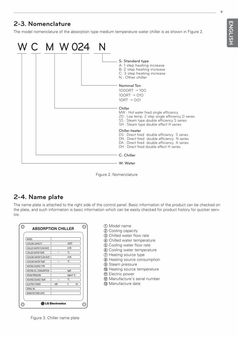
2-4. Name plateThe name plate is attached to the right side of the control panel. Basic information of the product can be checked onthe plate, and such information is basic information which can be easily checked for product history for quicker serv-ice.
ABSORPTION CHILLER
MODEL
COOLING CAPACITY
CHILLED WATER FLOW RATE
CHILLED WATER TEMP.
COOLING WATER FLOW RATE
COOLING WATER TEMP.
HEATING SOURCE TYPE
HEATING SO. CONSUMPTION
STEAM PRESSURE
HEATING SOURCE TEMP.
ELECTRIC POWER
SERIAL NO.
MANUFACTURED DATE
USRT
m3/h
°C
m3/h
°C
kg/h
kg/cm2 G
°C
V Hz~3Ø
Figure 3. Chiller name plate
①Model name② Cooling capacity③ Chilled water flow rate④ Chilled water temperature⑤ Cooling water flow rate⑥ Cooling water temperature⑦ Heating source type⑧ Heating source consumption⑨ Steam pressure⑩ Heating source temperature⑪ Electric power⑫Manufacture’s serial number ⑬Manufacture date
2-3. NomenclatureThe model nomenclature of the absorption type medium temperature water chiller is as shown in Figure 2.
W C NM W 024
ChillerMW : Hot water fired single efficiency2D : Low temp. 2 step single efficiency D seriesSS : Steam type double efficiency S seriesSH : Steam type double effect H series
Chiller-heaterDS : Direct fired double efficiency S seriesDN : Direct fired double efficiency N seriesDA : Direct fired double efficiency A seriesDH : Direct fired double effect H series
S: Standard typeA: 1 step heating increaseB: 2 step heating increaseC: 3 step heating increaseN : Other chiller
Nominal Ton1000RT → 100
100RT → 010
10RT → 001
C: Chiller
W: Water
Figure 2. Nomenclature
10
ENG
LISH
3. PREPARATION FOR INSTALLATION3-1. Checking site information• Before installing the absorption chiller, check the site beforehand, review necessary
Details and coordinate the following items with the site personnel so that the installation can be performed safelyand accurately.
1) JOB Data: Check the scope of the site installation work and the approval document.
2) Installation location: Check the environmental condition following 3-2 clause.
3) Access check: Check the size of the receiving dock (width, length & height) and plan ahead to avoid any prob-lems with the delivery, and check and review the access method and order sufficiently.
3-2. Condition for the installation site• To operate the machine efficiently and for easy maintenance, it is necessary to find a proper place for the equip-
ment related to the machine. Do not locate the machine in a narrow space which limits the user’s movement aswell as tube cleaning or storing the absorbent, or where ventilation is unavailable, which can cause a gas explosion.
Please select a proper place which satisfies the following conditions.
1) The machine room should be equipped with a sufficient ventilation system with a surrounding temperature main-tained at 5°C ~ 45°C.
2) Avoid places with high humidity or high amount of dust. Humidity or dust can cause electrical malfunctioning ofthe absorption chiller. For optimum operation, it is recommended to operate the machine in a place where therelative humidity is 20 ~ 80%RH.
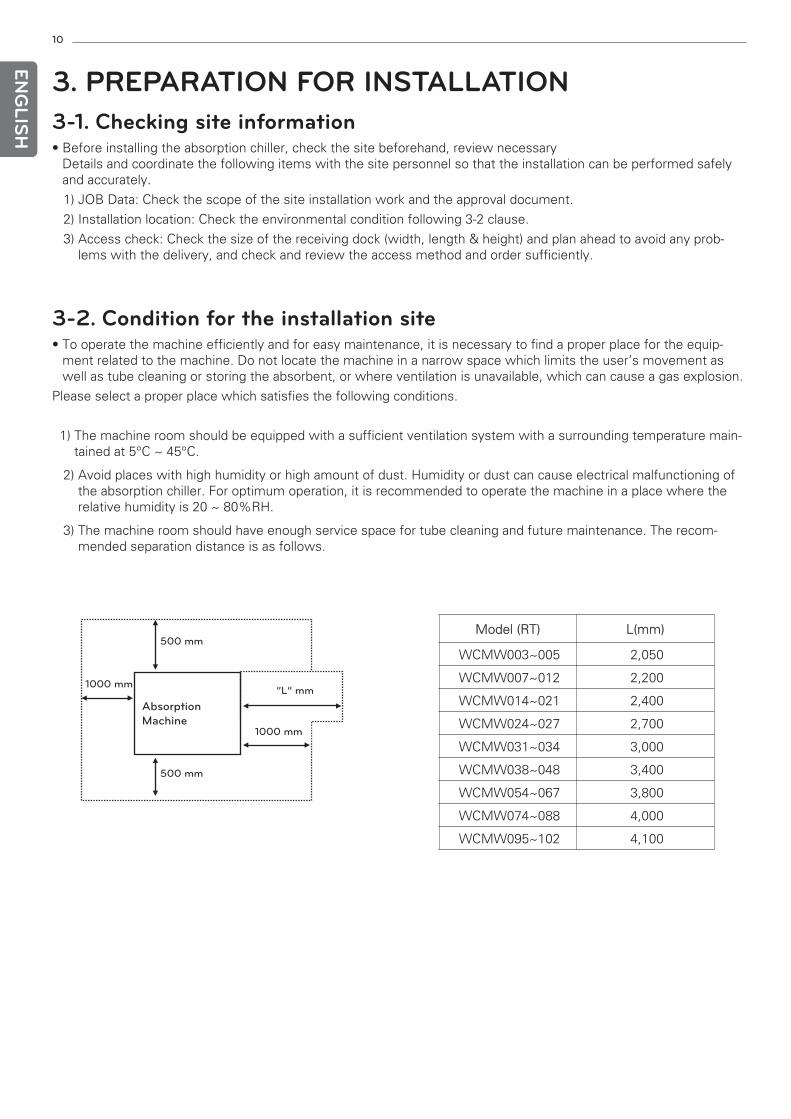
3) The machine room should have enough service space for tube cleaning and future maintenance. The recom-mended separation distance is as follows.
Model (RT) L(mm)
1000 mm
500 mm
Absorption Machine
1000 mm
500 mm
“L” mm
WCMW003~005 2,050
WCMW007~012 2,200
WCMW014~021 2,400
WCMW024~027 2,700
WCMW031~034 3,000
WCMW038~048 3,400
WCMW054~067 3,800
WCMW074~088 4,000
WCMW095~102 4,100
11
3-3. Foundation work considerations1) Before installing the absorption chiller, always secure the service space specified in the foundation drawing. It is
the minimum required space for maintenance.
2) For the installation of the absorption chiller, it should be firmly installed at a location where the running weightcan be endured based on the specifications indicated on the foundation drawing.
3) Make sure to arrange a drainage path for the chilled water and cooling water drainage for the cases of tube clean-ing of the absorption chiller and water disposal, and non-operation.
4) To guarantee the stable operation of the absorption chiller, level the absorption chiller by adjusting the levelingplate when installing. (The leveling degree should be within 2mm per 1,000mm)
5) Foundation work is out of the scope of LG. Please work according to the approved foundation drawing. LG Elec-tronics is not responsible for equipment problems due to an inappropriate foundation design and construction.
6) The foundation work should be done enough to support the weight of the machine so that it can maintain its hori-zontality. When installing on a roof or a upper place, vibration and noise must be considered.
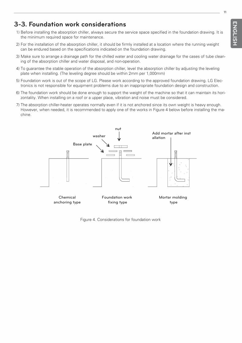
7) The absorption chiller-heater operates normally even if it is not anchored since its own weight is heavy enough.However, when needed, it is recommended to apply one of the works in Figure 4 below before installing the ma-chine.
ENG
LISH
Figure 4. Considerations for foundation work
Chemical anchoring type
Foundation work fixing type
Mortar molding type
washer
Base plate
nutAdd mortar after installation
12
ENG
LISH
3-4-3. Check after long-term storage1) When the long-term storage period is over 2 years, check through the site glass for any mechanical or electrical
problems before operating the machine again. If there are any problems, those should be checked by an LG engi-neer. After storing for a long period of time, it is recommended to have an inspection performed by a professionalservice agency.
2) When the product is left without any nitrogen pressure or refrigerant, have the machine checked by LG or a pro-fessional service engineer before operation.
3) Checking the electrical system
Check if there are any defects in the parts or problems in the pipe connection parts, and
measure the motor insulation resistance. For the checking procedure and judgment criteria,
proceed based on the procedure indicated in the operation and maintenance manual.
4) Checking the water system
The interior of the chilled water/cooling water system is expected to be contaminated due to the
inflow of dust or external particles when stopped for a long period. Clean the water system and
check the filter.
The cooling water system needs special care since it is generally of an open type piping system.
5) Perform commissioning based on the operation & maintenance manual.
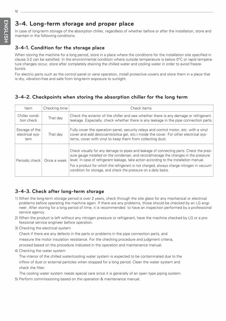
Item Checking time Check items
Chiller condi-tion check
That dayCheck the exterior of the chiller and see whether there is any damage or refrigerantleakage. Especially, check whether there is any leakage in the pipe connection parts.
Storage of theelectrical sys-
temThat day
Fully cover the operation panel, security relays and control motor, etc. with a vinylcover and add desiccants(silica gel, etc.) inside the cover. For other electrical sys-tems, cover with vinyl to keep them from collecting dust.
Periodic check Once a week
Check visually for any damage to pipes and leakage of connecting parts. Check the pres-sure gauge installed on the condenser, and record/manage the changes in the pressurelevel. In case of refrigerant leakage, take action according to the installation manual.
For a product for which the refrigerant is not charged, always charge nitrogen in vacuumcondition for storage, and check the pressure on a daily basis.
3-4-2. Checkpoints when storing the absorption chiller for the long term
3-4. Long-term storage and proper placeIn case of long-term storage of the absorption chiller, regardless of whether before or after the installation, store andmaintain in the following conditions.
3-4-1. Condition for the storage placeWhen storing the machine for a long period, store in a place where the conditions for the installation site specified inclause 3-2 can be satisfied. In the environmental condition where outside temperature is below 0°C or rapid tempera-ture changes occur, store after completely draining the chilled water and cooling water in order to avoid freeze-bursts.
For electric parts such as the control panel or vane operation, install protective covers and store them in a place thatis dry, vibration-free and safe from long-term exposure to sunlight.
13EN
GLIS
H
3-5. Cautions on product installationLG Electronics is not responsible for problems caused by not following the cautions.
3-5-1. Checkpoints before carrying in and installing the machine1) Check whether a ventilation system is equipped in the room where the absorption chiller is installed. 2) Select a place where the room temperature is below 40°C, ventilation is sufficient and the temperature is low.
Especially be aware of temperature rises in the long-term storage place and keep the room temperature below40°C.
3-5-2. Cautions when carrying in and installing the machine1) Move the machine in a fully balanced position. If the machine is subjected to impact or tilted, the refrigerant may
leak causing damage to the machine, so pay close attention.2) When raising the machine, be careful not to get the wires caught in valves or piping, etc.3) When raising or lowering the machine, be careful not to get the valves or piping to clash with columns or obsta-
cles.4) The carrying-in weight includes the weight of the charged refrigerant and oil. When carrying it in, always consider
the added weight.
3-5-3. Cautions after the installation1) During the processes of water pipe connection, safety valve exhaust pipe connection, insulation, etc., be careful
not to damage the valves, piping, etc. of the machine. 2) After completing the water piping work, be careful not to allow hot water to flow through. 3) In case of long-term storage, consult a service personnel.4) Always operate a ventilation system.
3-5-4. Action when liquid absorbent is leaking1) In case the liquid absorbent leaks out due to external damage or leakage, capture the leaking absorbent in a clean
vessel.2) Immediately after identifying the leakage or absorbent leakage, stop operation and contact LG. 3) If the leakage amount is small, wipe off with a dry cloth. If the amount is large, always capture it in a clean vessel.4) In the process of collecting the absorbent or filling in a vessel, if the absorbent contacts with skin or clothes, wipe
it off with soap water.
14
ENG
LISH
4. PRODUCT RECEIPT4-1. Check item list and product conditionAbsorption chiller is shipped either in the single unit type or separate unit type, and
charged with refrigerant or nitrogen depending on the situation of the site.
Check the specifications of the site.
1) Single unit type or separate unit typeFor the single unit type, all parts are preassembled upon delivery, and for the separate unit type, the product isseparated into 2 or 3 units upon delivery depending upon the site condition. Especially for the separate unit type,check and record whether all the parts are shipped properly according to the delivery list.
2) Refrigerant charged delivery or nitrogen charged deliveryFor the single unit type, the product is shipped with the refrigerant or nitrogen charged following the requestedconditions by the customer.For the refrigerant charged product, the absorbent and refrigerant which are required in the chiller are included.In case of nitrogen charging, it is shipped from the plant with a pressure of 0.3~0.5 kg/cm2·G.If the pressure is “0”, record the condition as there is a danger of leakage, and always check for any leakage.
4-2. Product inspection1) Check whether the packing list and the receipt list match each other.
2) Check the information on the product plate against the project information.Refer to clause 2-4 for details on the information on the plate.
3) Check the exterior condition of the product and check if there are any damages or leakages.If any damaged parts are found on the equipment, first check the safety of the damaged parts (refrigerant or ab-sorbent leakage, etc.), and if there is no damage, procure a photograph and contact an LG engineer for furtheraction.
4-3. Product protectionWhen receiving the product, check and record the following details to protect the product.
1) When shipped, the product is charged with refrigerant or nitrogen to prevent corrosion from external moisturepenetration. Be careful not to randomly operate or open the valve and connector attached to the product. If thewater box is sealed with a blank flange, nitrogen is charged at a pressure of 0.3 ~0.5kg/cm2·G. Therefore, purgewith nitrogen first and then open the flange.
2) When receiving the product, check the exterior and pipe condition, and check and record any leakage from dam-ages or loose bolts.
3) If the product is damaged, or if there is an issue with a part when checking, immediately provide the details ofthe problem to the delivery personnel and contact the personnel in charge at LG Electronics. A damaged productshould not be installed without the approval of LG.
15
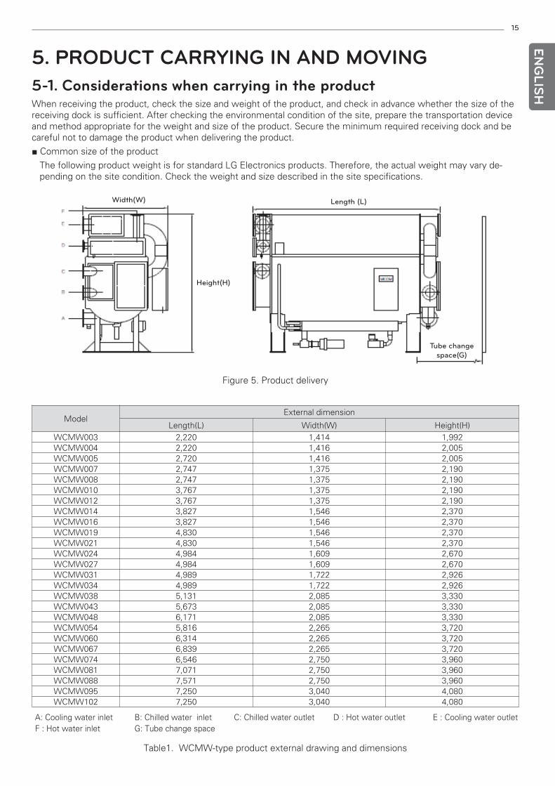
5. PRODUCT CARRYING IN AND MOVING5-1. Considerations when carrying in the productWhen receiving the product, check the size and weight of the product, and check in advance whether the size of thereceiving dock is sufficient. After checking the environmental condition of the site, prepare the transportation deviceand method appropriate for the weight and size of the product. Secure the minimum required receiving dock and becareful not to damage the product when delivering the product.
■ Common size of the product
The following product weight is for standard LG Electronics products. Therefore, the actual weight may vary de-pending on the site condition. Check the weight and size described in the site specifications.
ENG
LISH
Width(W)
Height(H)
Length (L)
Tube changespace(G)
Table1. WCMW-type product external drawing and dimensions
Figure 5. Product delivery
A: Cooling water inlet F : Hot water inlet
B: Chilled water inlet G: Tube change space
C: Chilled water outlet D : Hot water outlet E : Cooling water outlet
ModelExternal dimension
Length(L) Width(W) Height(H)WCMW003 2,220 1,414 1,992WCMW004 2,220 1,416 2,005WCMW005 2,720 1,416 2,005WCMW007 2,747 1,375 2,190WCMW008 2,747 1,375 2,190WCMW010 3,767 1,375 2,190WCMW012 3,767 1,375 2,190WCMW014 3,827 1,546 2,370WCMW016 3,827 1,546 2,370WCMW019 4,830 1,546 2,370WCMW021 4,830 1,546 2,370WCMW024 4,984 1,609 2,670WCMW027 4,984 1,609 2,670WCMW031 4,989 1,722 2,926WCMW034 4,989 1,722 2,926WCMW038 5,131 2,085 3,330WCMW043 5,673 2,085 3,330WCMW048 6,171 2,085 3,330WCMW054 5,816 2,265 3,720WCMW060 6,314 2,265 3,720WCMW067 6,839 2,265 3,720WCMW074 6,546 2,750 3,960WCMW081 7,071 2,750 3,960WCMW088 7,571 2,750 3,960WCMW095 7,250 3,040 4,080WCMW102 7,250 3,040 4,080
16
ENG
LISH
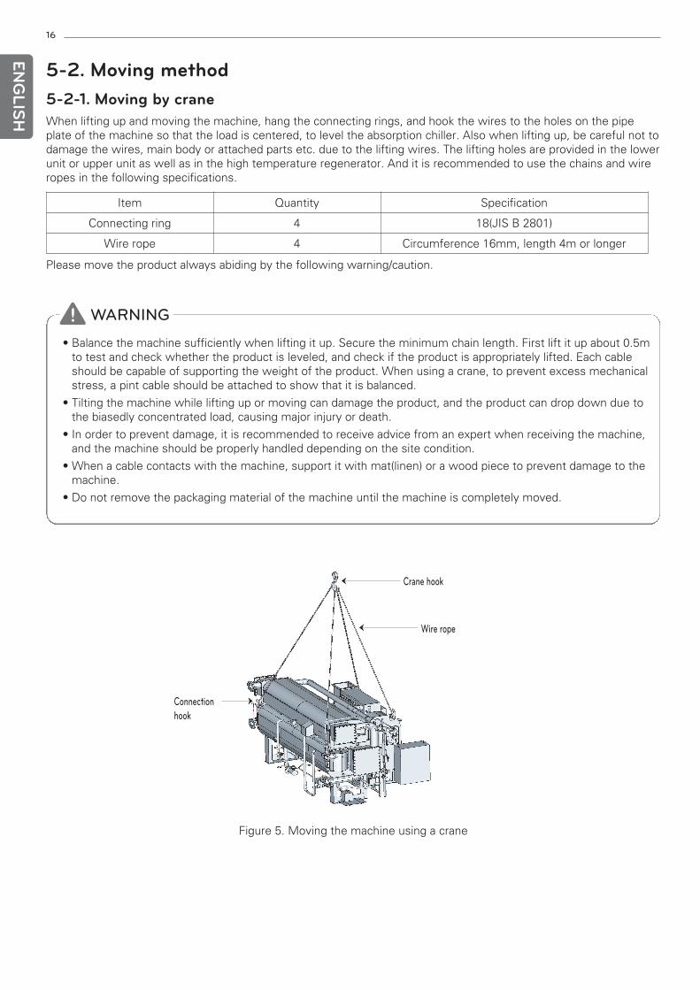
5-2. Moving method5-2-1. Moving by craneWhen lifting up and moving the machine, hang the connecting rings, and hook the wires to the holes on the pipeplate of the machine so that the load is centered, to level the absorption chiller. Also when lifting up, be careful not todamage the wires, main body or attached parts etc. due to the lifting wires. The lifting holes are provided in the lowerunit or upper unit as well as in the high temperature regenerator. And it is recommended to use the chains and wireropes in the following specifications.
Please move the product always abiding by the following warning/caution.
! WARNING
• Balance the machine sufficiently when lifting it up. Secure the minimum chain length. First lift it up about 0.5mto test and check whether the product is leveled, and check if the product is appropriately lifted. Each cableshould be capable of supporting the weight of the product. When using a crane, to prevent excess mechanicalstress, a pint cable should be attached to show that it is balanced.
• Tilting the machine while lifting up or moving can damage the product, and the product can drop down due tothe biasedly concentrated load, causing major injury or death.
• In order to prevent damage, it is recommended to receive advice from an expert when receiving the machine,and the machine should be properly handled depending on the site condition.
• When a cable contacts with the machine, support it with mat(linen) or a wood piece to prevent damage to themachine.
• Do not remove the packaging material of the machine until the machine is completely moved.
Figure 5. Moving the machine using a crane
Crane hook
Wire rope
Connection hook
Item Quantity Specification
Connecting ring 4 18(JIS B 2801)
Wire rope 4 Circumference 16mm, length 4m or longer
17EN
GLIS
H
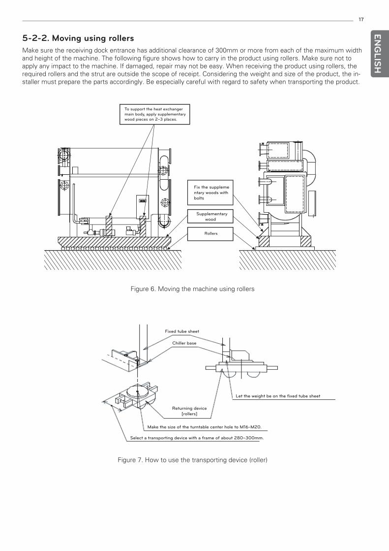
5-2-2. Moving using rollersMake sure the receiving dock entrance has additional clearance of 300mm or more from each of the maximum widthand height of the machine. The following figure shows how to carry in the product using rollers. Make sure not toapply any impact to the machine. If damaged, repair may not be easy. When receiving the product using rollers, therequired rollers and the strut are outside the scope of receipt. Considering the weight and size of the product, the in-staller must prepare the parts accordingly. Be especially careful with regard to safety when transporting the product.
Rollers
Supplementarywood
Fix the supplementary woods withbolts
To support the heat exchanger main body, apply supplementarywood pieces on 2~3 places.
Chiller base
Returning device[rollers]
Fixed tube sheet
Let the weight be on the fixed tube sheet
Make the size of the turntable center hole to M16-M20.
Select a transporting device with a frame of about 280~300mm.
Figure 6. Moving the machine using rollers
Figure 7. How to use the transporting device (roller)
18
ENG
LISH
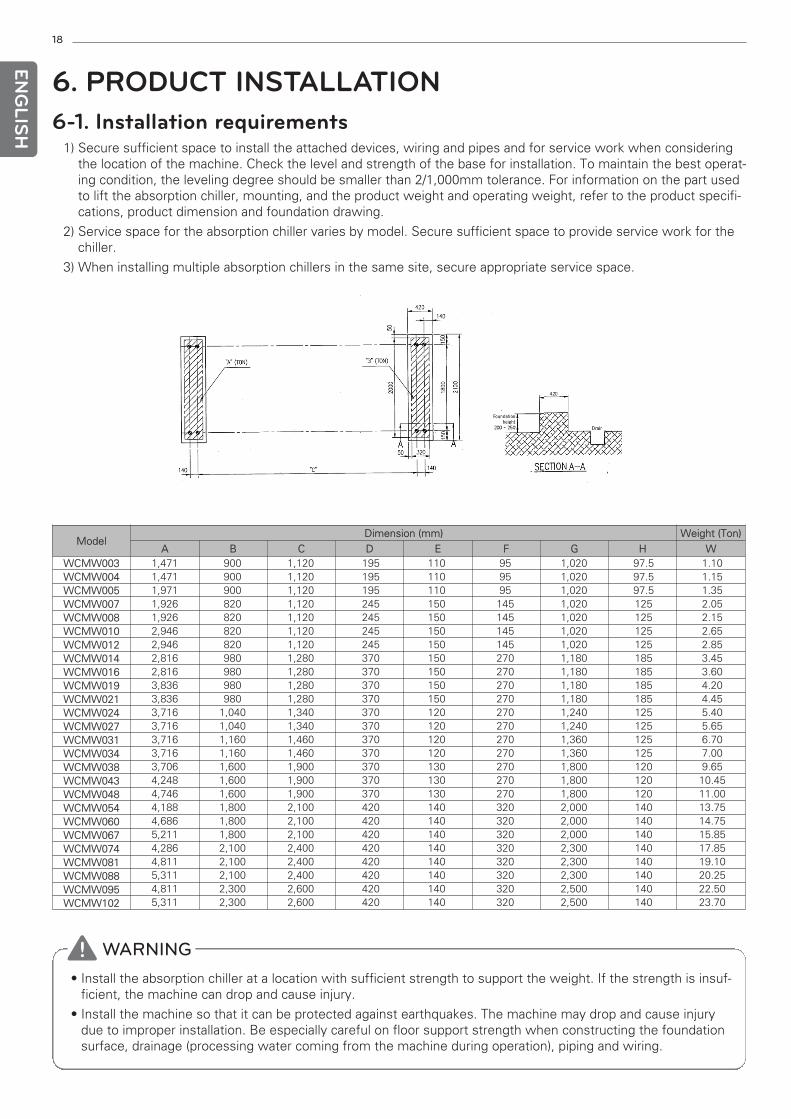
6. PRODUCT INSTALLATION6-1. Installation requirements
1) Secure sufficient space to install the attached devices, wiring and pipes and for service work when consideringthe location of the machine. Check the level and strength of the base for installation. To maintain the best operat-ing condition, the leveling degree should be smaller than 2/1,000mm tolerance. For information on the part usedto lift the absorption chiller, mounting, and the product weight and operating weight, refer to the product specifi-cations, product dimension and foundation drawing.
2) Service space for the absorption chiller varies by model. Secure sufficient space to provide service work for thechiller.
3) When installing multiple absorption chillers in the same site, secure appropriate service space.
Foundationheight
200 ~ 250
FoFoFFounFounFounFoun
200200200200200200200200
420
ddd tititndandandandationtiontiontionheightheightheightheigh 25025025025~~~~ 250250250250 Drain
420420420420420420420420
DrainDrainDrainDrain
! WARNING• Install the absorption chiller at a location with sufficient strength to support the weight. If the strength is insuf-
ficient, the machine can drop and cause injury.
• Install the machine so that it can be protected against earthquakes. The machine may drop and cause injurydue to improper installation. Be especially careful on floor support strength when constructing the foundationsurface, drainage (processing water coming from the machine during operation), piping and wiring.
ModelDimension (mm) Weight (Ton)
A B C D E F G H WWCMW003WCMW004WCMW005WCMW007WCMW008WCMW010WCMW012WCMW014WCMW016WCMW019WCMW021WCMW024WCMW027WCMW031WCMW034WCMW038WCMW043WCMW048WCMW054WCMW060WCMW067WCMW074WCMW081WCMW088WCMW095WCMW102
1,471 900 1,120 195 110 95 1,020 97.5 1.101,471 900 1,120 195 110 95 1,020 97.5 1.151,971 900 1,120 195 110 95 1,020 97.5 1.351,926 820 1,120 245 150 145 1,020 125 2.051,926 820 1,120 245 150 145 1,020 125 2.152,946 820 1,120 245 150 145 1,020 125 2.652,946 820 1,120 245 150 145 1,020 125 2.852,816 980 1,280 370 150 270 1,180 185 3.452,816 980 1,280 370 150 270 1,180 185 3.603,836 980 1,280 370 150 270 1,180 185 4.203,836 980 1,280 370 150 270 1,180 185 4.453,716 1,040 1,340 370 120 270 1,240 125 5.403,716 1,040 1,340 370 120 270 1,240 125 5.653,716 1,160 1,460 370 120 270 1,360 125 6.703,716 1,160 1,460 370 120 270 1,360 125 7.003,706 1,600 1,900 370 130 270 1,800 120 9.654,248 1,600 1,900 370 130 270 1,800 120 10.454,746 1,600 1,900 370 130 270 1,800 120 11.004,188 1,800 2,100 420 140 320 2,000 140 13.754,686 1,800 2,100 420 140 320 2,000 140 14.755,211 1,800 2,100 420 140 320 2,000 140 15.854,286 2,100 2,400 420 140 320 2,300 140 17.854,811 2,100 2,400 420 140 320 2,300 140 19.105,311 2,100 2,400 420 140 320 2,300 140 20.254,811 2,300 2,600 420 140 320 2,500 140 22.505,311 2,300 2,600 420 140 320 2,500 140 23.70
19EN
GLIS
H
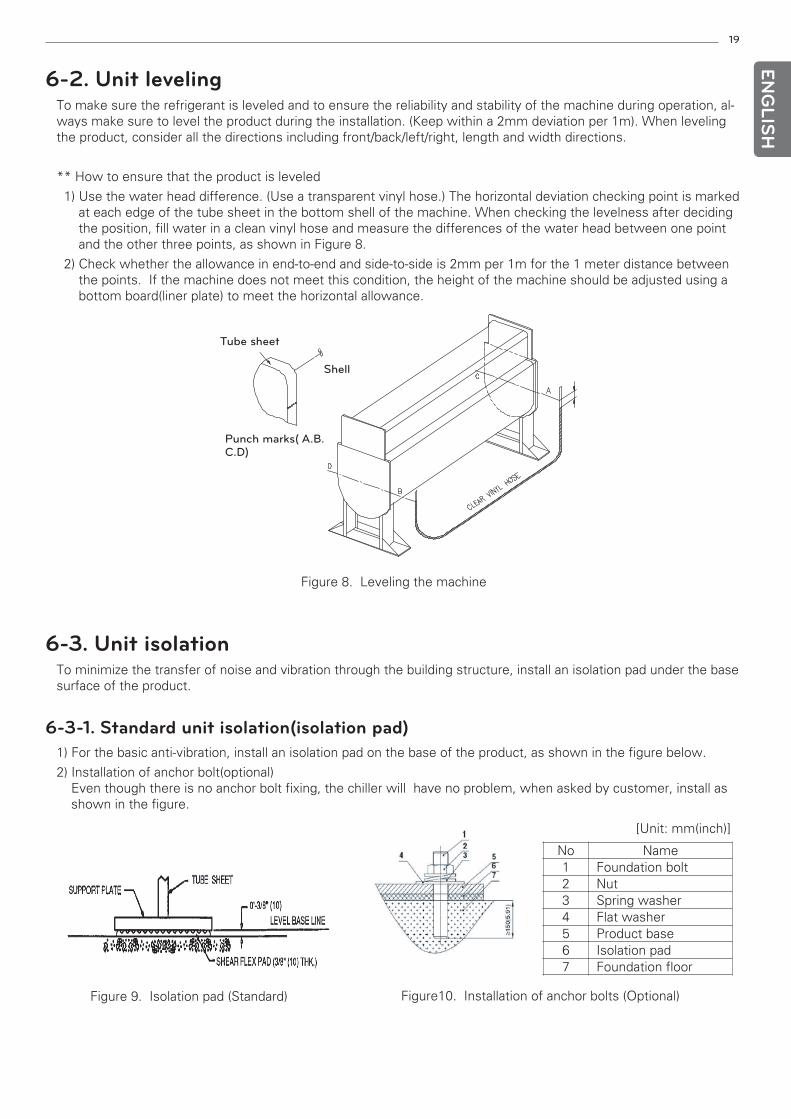
6-2. Unit levelingTo make sure the refrigerant is leveled and to ensure the reliability and stability of the machine during operation, al-ways make sure to level the product during the installation. (Keep within a 2mm deviation per 1m). When levelingthe product, consider all the directions including front/back/left/right, length and width directions.
** How to ensure that the product is leveled
1) Use the water head difference. (Use a transparent vinyl hose.) The horizontal deviation checking point is markedat each edge of the tube sheet in the bottom shell of the machine. When checking the levelness after decidingthe position, fill water in a clean vinyl hose and measure the differences of the water head between one pointand the other three points, as shown in Figure 8.
2) Check whether the allowance in end-to-end and side-to-side is 2mm per 1m for the 1 meter distance betweenthe points. If the machine does not meet this condition, the height of the machine should be adjusted using abottom board(liner plate) to meet the horizontal allowance.
6-3. Unit isolationTo minimize the transfer of noise and vibration through the building structure, install an isolation pad under the basesurface of the product.
6-3-1. Standard unit isolation(isolation pad)1) For the basic anti-vibration, install an isolation pad on the base of the product, as shown in the figure below.
2) Installation of anchor bolt(optional)Even though there is no anchor bolt fixing, the chiller will have no problem, when asked by customer, install asshown in the figure.
Figure 8. Leveling the machine
Tube sheet
Shell
Punch marks( A.B.C.D)
Figure 9. Isolation pad (Standard) Figure10. Installation of anchor bolts (Optional)
[Unit: mm(inch)]
No Name 1 Foundation bolt 2 Nut 3 Spring washer 4 Flat washer 5 Product base 6 Isolation pad 7 Foundation floor
20
ENG
LISH
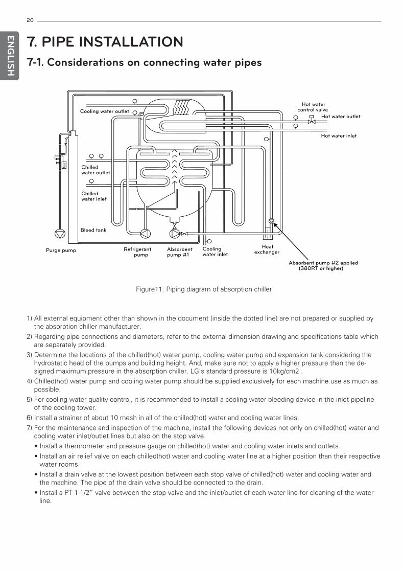
7. PIPE INSTALLATION7-1. Considerations on connecting water pipes
1) All external equipment other than shown in the document (inside the dotted line) are not prepared or supplied bythe absorption chiller manufacturer.
2) Regarding pipe connections and diameters, refer to the external dimension drawing and specifications table whichare separately provided.
3) Determine the locations of the chilled(hot) water pump, cooling water pump and expansion tank considering thehydrostatic head of the pumps and building height. And, make sure not to apply a higher pressure than the de-signed maximum pressure in the absorption chiller. LG’s standard pressure is 10kg/cm2 .
4) Chilled(hot) water pump and cooling water pump should be supplied exclusively for each machine use as much aspossible.
5) For cooling water quality control, it is recommended to install a cooling water bleeding device in the inlet pipelineof the cooling tower.
6) Install a strainer of about 10 mesh in all of the chilled(hot) water and cooling water lines.
7) For the maintenance and inspection of the machine, install the following devices not only on chilled(hot) water andcooling water inlet/outlet lines but also on the stop valve.
• Install a thermometer and pressure gauge on chilled(hot) water and cooling water inlets and outlets.
• Install an air relief valve on each chilled(hot) water and cooling water line at a higher position than their respectivewater rooms.
• Install a drain valve at the lowest position between each stop valve of chilled(hot) water and cooling water andthe machine. The pipe of the drain valve should be connected to the drain.
• Install a PT 1 1/2” valve between the stop valve and the inlet/outlet of each water line for cleaning of the waterline.
Purge pump Refrigerantpump
Absorbentpump #1
Coolingwater inlet
Heatexchanger
Hot water outlet
Hot water inlet
Hot watercontrol valve Cooling water outlet
Chilledwater outlet
Chilledwater inlet
Bleed tank
Absorbent pump #2 applied(380RT or higher)
Figure11. Piping diagram of absorption chiller
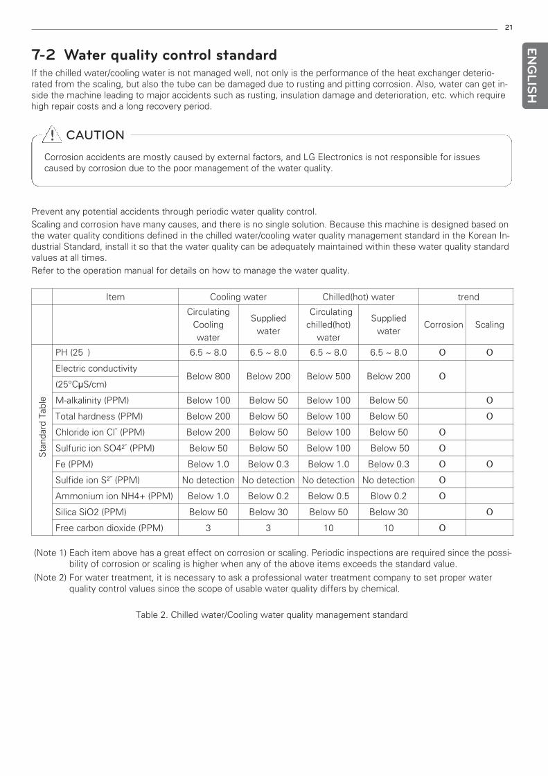
Prevent any potential accidents through periodic water quality control.Scaling and corrosion have many causes, and there is no single solution. Because this machine is designed based onthe water quality conditions defined in the chilled water/cooling water quality management standard in the Korean In-dustrial Standard, install it so that the water quality can be adequately maintained within these water quality standardvalues at all times.Refer to the operation manual for details on how to manage the water quality.
(Note 1) Each item above has a great effect on corrosion or scaling. Periodic inspections are required since the possi-bility of corrosion or scaling is higher when any of the above items exceeds the standard value.
(Note 2) For water treatment, it is necessary to ask a professional water treatment company to set proper waterquality control values since the scope of usable water quality differs by chemical.
Table 2. Chilled water/Cooling water quality management standard
21
7-2 Water quality control standardIf the chilled water/cooling water is not managed well, not only is the performance of the heat exchanger deterio-rated from the scaling, but also the tube can be damaged due to rusting and pitting corrosion. Also, water can get in-side the machine leading to major accidents such as rusting, insulation damage and deterioration, etc. which requirehigh repair costs and a long recovery period.
ENG
LISH
! CAUTION
Corrosion accidents are mostly caused by external factors, and LG Electronics is not responsible for issuescaused by corrosion due to the poor management of the water quality.
Item Cooling water Chilled(hot) water trend
CirculatingCoolingwater
Suppliedwater
Circulatingchilled(hot)
water
Suppliedwater
Corrosion Scaling
Sta
ndar
d Ta
ble
PH (25℃) 6.5 ~ 8.0 6.5 ~ 8.0 6.5 ~ 8.0 6.5 ~ 8.0 O O
Electric conductivityBelow 800 Below 200 Below 500 Below 200 O
(25°CμS/cm)
M-alkalinity (PPM) Below 100 Below 50 Below 100 Below 50 O
Total hardness (PPM) Below 200 Below 50 Below 100 Below 50 O
Chloride ion Cl¯ (PPM) Below 200 Below 50 Below 100 Below 50 O
Sulfuric ion SO4²¯ (PPM) Below 50 Below 50 Below 100 Below 50 O
Fe (PPM) Below 1.0 Below 0.3 Below 1.0 Below 0.3 O O
Sulfide ion S²¯ (PPM) No detection No detection No detection No detection O
Ammonium ion NH4+ (PPM) Below 1.0 Below 0.2 Below 0.5 Blow 0.2 O
Silica SiO2 (PPM) Below 50 Below 30 Below 50 Below 30 O
Free carbon dioxide (PPM) 3 3 10 10 O
22
ENG
LISH
7-2-2 Water quality control during long-term stopWhen stopping the operation for a long period without flowing chilled water, cooling water or hot water, manage thewater quality by applying the following standards.
• Cooling water system
In principle, the cooling water system should be stored with water filled full in the machine. However, if there is adanger of the cooling water freezing in the machine, the inside of the tube(water room side) should be dried andstored. Be careful since the valve opening and closing are different for full water storage and dry storage respec-tively.
*In case of full water storage
(1) Drain the water which was flowing during operation through the cooling water
drain pipe.
(2) Add anticorrosive.
Check the full water amount of the machine and add the proper amount of anticorrosive in the right mixingratio.
(3) Fill new water into the pipe.
(4) Run the cooling water pump for a while so that the anticorrosive can be mixed evenly.
(5) Close all of the cooling water inlet/outlet valves(blocking valves in the pipe to the
equipment side).
(6) Open the main body side’s cooling/heating conversion D valve of the chiller-heater.
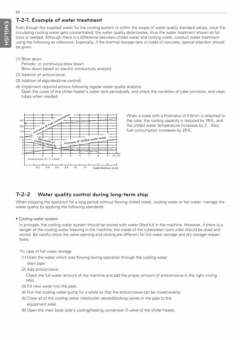
Increase of chilled water temp
Increase of fuel consumption
.Decrease ofChilling capacity
Scale thicknes (mm)
130
0.2
1 2 3 4 5 6 7 8 9 10 x 10
0.4 0.6 0.8 10 12
120
110
100543210
Fouling factor (m2 . h . c/kcal)
When a scale with a thickness of 0.6mm is attached tothe tube, the cooling capacity is reduced by 76%, andthe chilled water temperature increases by 2℃. Also,fuel consumption increases by 25%.
7-2-1. Example of water treatmentEven though the supplied water for the cooling system is within the scope of water quality standard values, once thecirculating cooling water gets concentrated, the water quality deteriorates, thus the water treatment shown as fol-lows is needed. Although there is a difference between chilled water and cooling water, conduct water treatmentusing the following as reference. Especially, if the thermal storage tank is made of concrete, special attention shouldbe given.
(1) Blow downPeriodic or continuous blow down.Blow down based on electric conductivity analysis.
(2) Addition of anticorrosive
(3) Addition of algicide(slime control)
(4) Implement required actions following regular water quality analysisOpen the cover of the chiller-heater’s water tank periodically, and check the condition of tube corrosion, and cleantubes when needed.
23EN
GLIS
H
* In case of dry storage.
Clean the insides of tubes and create an anticorrosion layer, then dry store the machine.
(1) Drain the water which was flowing during operation through the cooling water drain pipe.
(2) Clean the insides of tubes to remove scale and slime attached to the tube insides. If mechanical cleaning is in-sufficient, conduct chemical cleaning in parallel.
(3) After cleaning the insides of the tubes sufficiently, add anticorrosive and fill water.
(4) Run the cooling water pump for over 30 minutes so that the anticorrosive can be mixed completely.
(5) Drain water completely and open the cooling water drain valve to dry store while the drain valve is kept open.
• Chilled water system
In principle, store with full water in the machine.
7-2-3. Measures for wintertime• When the temperature surrounding the chiller is below 0°C in wintertime, various measures are needed. Do not let
the chilled water freeze by continuing the heating operation(operate the chiller in pre-designated times by using thereservation run function in micom) or keep the pump running. And when dry storing the cooling water system,open the drain valve of the cooling water system at all times to prevent freezing due to the water room being filledwith condensed water. In case of full water storage, antifreeze solution should be added to the cooling water sys-tem. However, since the equipment condition varies by site, consult a service center for details.
24
ENG
LISH
8. THERMAL INSULATION WORKLG Electronics does not perform thermal insulation work to the product when delivering the product. Perform ther-mal insulation work before commissioning after the leakage test on the site.
Perform thermal insulation work based on the standard thermal insulation guideline. LG(95)-G-2067-01
• Cautions on thermal insulation work
1) Heat insulator
- Flame retardant synthetic rubber blowing agent: Thermal resistance: 120°C or higher, Thermal conductivity:0.033kcal/mh°C or lower
- Glass wool or asbestos: Cover exterior surface with an aluminum or tin plate.
2) Cold insulator
- Flame retardant synthetic rubber blowing agent: Thermal conductivity 0.033kcal/mh°C or lower
- Apply adhesive evenly on the surface (purpose: to prevent moisture condensation)
3) Hot and cold insulation for the chilled water box and hot water box should be done in such a way as to allow thewater boxes to be separated.
4) Do not cold insulate the motor area of the refrigerant pump located at the lower part of the evaporator.
5) The cold insulation area and the taping hot insulation area should be in the same color, and finish-painted with apaint of the same specification as the main body.
25EN
GLIS
H
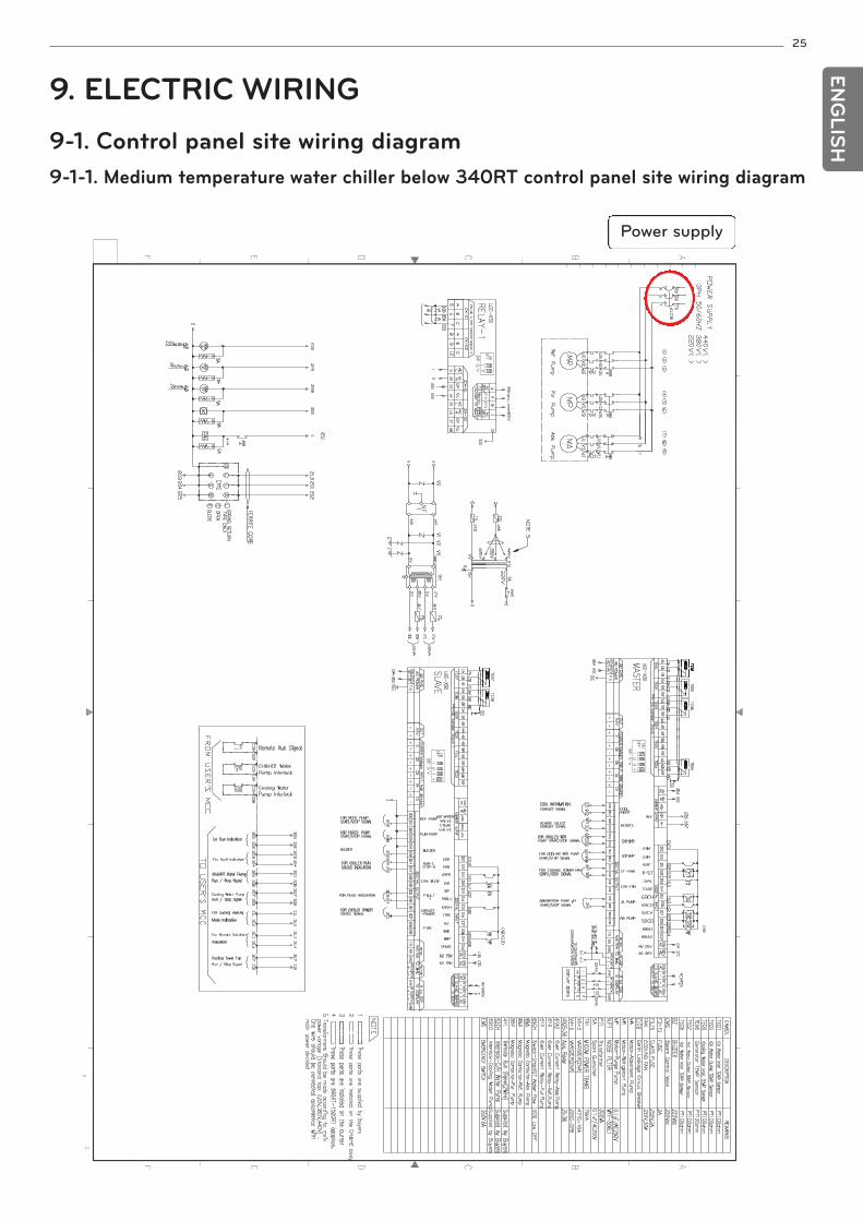
9. ELECTRIC WIRING9-1. Control panel site wiring diagram9-1-1. Medium temperature water chiller below 340RT control panel site wiring diagram
Power supply
26
ENG
LISH
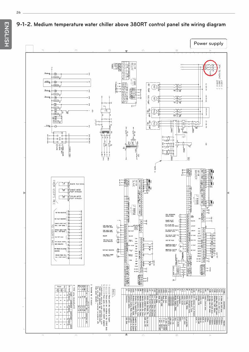
9-1-2. Medium temperature water chiller above 380RT control panel site wiring diagram
Power supply
27EN
GLIS
H
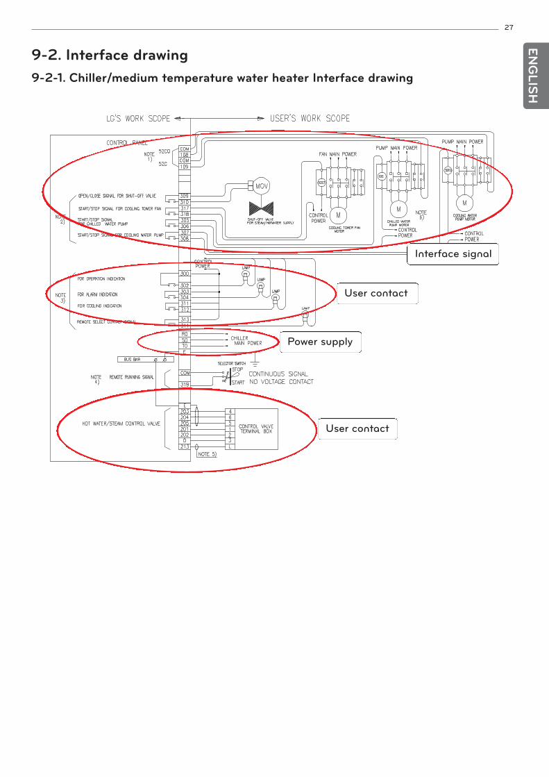
9-2. Interface drawing9-2-1. Chiller/medium temperature water heater Interface drawing
Interface signal
User contact
Power supply
User contact
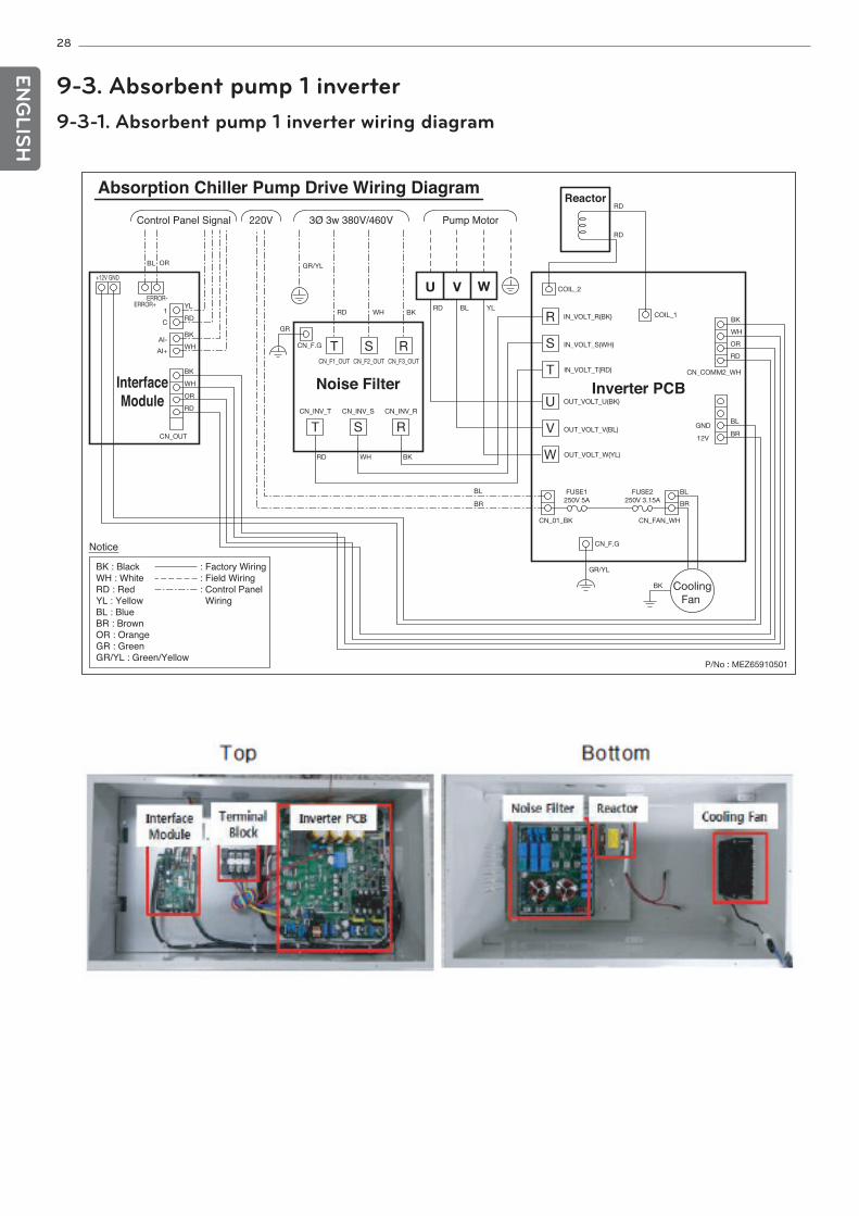
9-3. Absorbent pump 1 inverter9-3-1. Absorbent pump 1 inverter wiring diagram
28
ENG
LISH
= 29EN
GLIS
H
10. APPENDIX
10-1. Installation checklist(1/3)
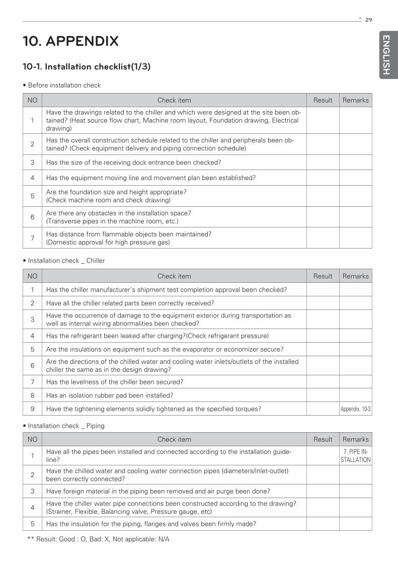
• Before installation check
NO Check item Result Remarks
1Have the drawings related to the chiller and which were designed at the site been ob-tained? (Heat source flow chart, Machine room layout, Foundation drawing, Electricaldrawing)
2Has the overall construction schedule related to the chiller and peripherals been ob-tained? (Check equipment delivery and piping connection schedule)
3 Has the size of the receiving dock entrance been checked?
4 Has the equipment moving line and movement plan been established?
5Are the foundation size and height appropriate? (Check machine room and check drawing)
6Are there any obstacles in the installation space? (Transverse pipes in the machine room, etc.)
7Has distance from flammable objects been maintained? (Domestic approval for high pressure gas)
NO Check item Result Remarks
1 Has the chiller manufacturer’s shipment test completion approval been checked?
2 Have all the chiller related parts been correctly received?
3Have the occurrence of damage to the equipment exterior during transportation aswell as internal wiring abnormalities been checked?
4 Has the refrigerant been leaked after charging?(Check refrigerant pressure)
5 Are the insulations on equipment such as the evaporator or economizer secure?
6Are the directions of the chilled water and cooling water inlets/outlets of the installedchiller the same as in the design drawing?
7 Has the levelness of the chiller been secured?
8 Has an isolation rubber pad been installed?
9 Have the tightening elements solidly tightened as the specified torques? Appendix. 10-3
• Installation check _ Chiller
NO Check item Result Remarks
1Have all the pipes been installed and connected according to the installation guide-line?
7. PIPE IN-STALLATION
2Have the chilled water and cooling water connection pipes (diameters/inlet-outlet)been correctly connected?
3 Have foreign material in the piping been removed and air purge been done?
4Have the chiller water pipe connections been constructed according to the drawing?(Strainer, Flexible, Balancing valve, Pressure gauge, etc)
5 Has the insulation for the piping, flanges and valves been firmly made?
• Installation check _ Piping
** Result: Good : O, Bad: X, Not applicable: N/A
30
ENG
LISH
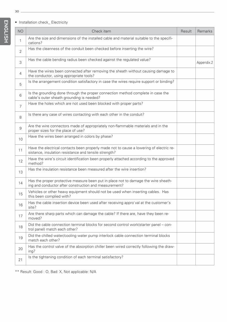
NO Check item Result Remarks
1Are the size and dimensions of the installed cable and material suitable to the specifi-cations?
2Has the cleanness of the conduit been checked before inserting the wire?
3Has the cable bending radius been checked against the regulated value?
Appendix.2
4Have the wires been connected after removing the sheath without causing damage tothe conductor, using appropriate tools?
5Is the arrangement condition satisfactory in case the wires require support or binding?
6Is the grounding done through the proper connection method complete in case thecable’s outer sheath grounding is needed?
7Have the holes which are not used been blocked with proper parts?
8Is there any case of wires contacting with each other in the conduit?
9Are the wire connectors made of appropriately non-flammable materials and in theproper sizes for the place of use?
10Have the wires been arranged in colors by phase?
11Have the electrical contacts been properly made not to cause a lowering of electric re-sistance, insulation resistance and tensile strength?
12Have the wire’s circuit identification been properly attached according to the approvedmethod?
13Has the insulation resistance been measured after the wire insertion?
14Has the proper protective measure been put in place not to damage the wire sheath-ing and conductor after construction and measurement?
15Vehicles or other heavy equipment should not be used when inserting cables. Hasthis been complied with?
16Has the cable insertion device been used after receiving appro`val at the customer’ssite?
17Are there sharp parts which can damage the cable? If there are, have they been re-moved?
18Did the cable connection terminal blocks for second control work(starter panel – con-trol panel) match each other?
19Did the chilled water/cooling water pump interlock cable connection terminal blocksmatch each other?
20Has the control valve of the absorption chiller been wired correctly following the draw-ing?
21Is the tightening condition of each terminal satisfactory?
• Installation check_ Electricity
** Result: Good : O, Bad: X, Not applicable: N/A
31EN
GLIS
H
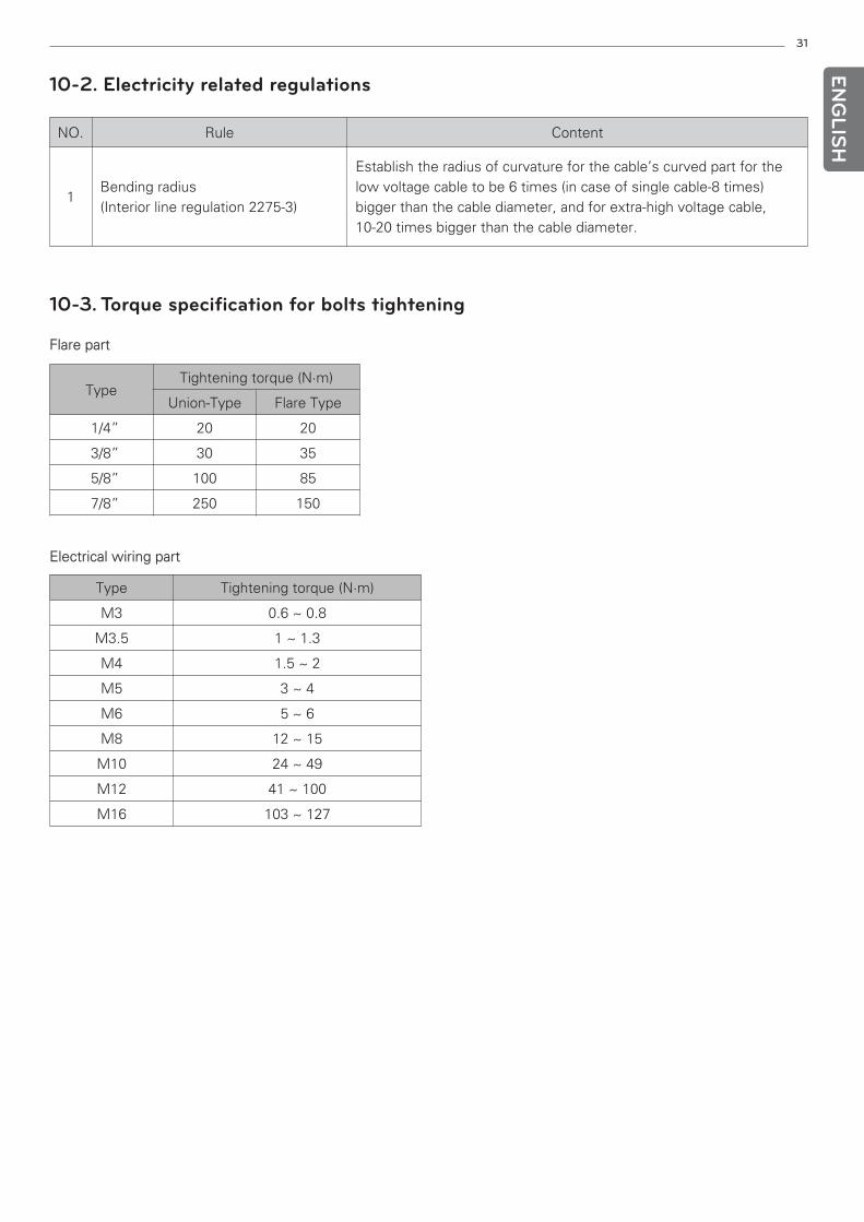
10-2. Electricity related regulations
NO. Rule Content
1Bending radius(Interior line regulation 2275-3)
Establish the radius of curvature for the cable’s curved part for thelow voltage cable to be 6 times (in case of single cable-8 times)bigger than the cable diameter, and for extra-high voltage cable,10-20 times bigger than the cable diameter.
10-3. Torque specification for bolts tightening
Flare part
Electrical wiring part
Type Tightening torque (N·m)
Union-Type Flare Type
1/4” 20 20
3/8” 30 35
5/8” 100 85
7/8” 250 150
Type Tightening torque (N·m)
M3 0.6 ~ 0.8
M3.5 1 ~ 1.3
M4 1.5 ~ 2
M5 3 ~ 4
M6 5 ~ 6
M8 12 ~ 15
M10 24 ~ 49
M12 41 ~ 100
M16 103 ~ 127

32
ENG
LISH