Embed Size (px)
Citation preview

Issue Date: 01.06.16 Review Date: 01.06.16
Installation Manual for CHW Systems: MAN_INST_CHW(AA) |1
Apricus Solar Hot Water Installation Manual
For Commercial Hot Water Systems

Issue Date: 01.06.16 Review Date: 01.06.16
Installation Manual for CHW Systems: MAN_INST_CHW(AA) |2
CONTENTS
CHAPTER 1: INTRODUCTION ............................................................................................................................................... 3
CHAPTER 2: WARNINGS AND PRECAUTIONS ...................................................................................................................... 4
CHAPTER 3: SITE INSPECTION ............................................................................................................................................. 7
CHAPTER 4: COMPONENT INSPECTION ............................................................................................................................ 10
CHAPTER 5: FRAMING ....................................................................................................................................................... 12
CHAPTER 6: SYSTEM PLUMBING ....................................................................................................................................... 18
CHAPTER 7: COMMISSIONING .......................................................................................................................................... 22
CHAPTER 8: AUXILIARY HEATING ...................................................................................................................................... 25
CHAPTER 9: POST INSTALLATION ...................................................................................................................................... 26
CHAPTER 10: APPENDIX .................................................................................................................................................. 27

Issue Date: 01.06.16 Review Date: 01.06.16
Installation Manual for CHW Systems: MAN_INST_CHW(AA) |3
CHAPTER 1: INTRODUCTION
TERMINOLOGY Bank: Multiple collectors in series (one after the
other).
Boost: The process where a heating component
(such as an electric element or gas heater) is used to
provide additional heating when solar-heated water
is not of an adequate temperature
Clean Energy Regulator (CER): Government body
responsible for overseeing the implementation of
the Large-scale Renewable Energy Target (LRET) and
the Small-scale Renewable Energy Scheme (SRES).
Collector: The Apricus solar collector includes the
manifold with heat pipes and evacuated tubes
inserted.
Expansion Control Valve (ECV): Installed on the cold
mains line to relieve excess pressure.
Expansion Tank: Fitting an Expansion Tank to the
system allows the water to move into the expansion
tank and occupy its volume, rather than increasing
the system pressure. This reduces the wastage of
water through the PTRV and protects the system
from high pressures and undue wear.
Evacuated Tube: functions to harness the solar
energy by capturing and retaining the heat due to
the presence of the vacuum.
Flow Line: The plumbing line running from tank solar
flow port to the inlet of the collector. This line
incorporates the circulation pump.
Heat Pipe: A copper pipe that sits inside the
evacuated tube and is inserted into the collector
manifold. A small volume of liquid acts as a heat
transfer fluid. It absorbs heat via evaporation, and
transfers heat to the system fluid via condensation.
Header Pipes: The copper “heat exchanger pipes” in
the manifold of the Apricus collector through which
the water flows.
Insolation: solar radiation level, expressed in
kWh/m2/day.
Manifold: Refers to the solar collector enclosure that
contains the header pipes.
Pressure Temperature Relief Valve (PTRV): installed
on the hot water storage tank to relieve pressure,
and excessive temperatures.
Return Line: The plumbing line running from the
solar collector to the solar return port on the tank.
Stagnation: Stagnation is the maximum temperature
a collector will reach, at which point the rate of heat
gain and rate of heat loss is balanced.
Stratification - the passive separation of water into
distinct layers of different temperatures; where the
temperature at the top of the tank can be
significantly higher than the temperature at the
bottom.
1.2 SCOPE This manual has been designed to provide
installation instructions for the installer or plumber.

Issue Date: 01.06.16 Review Date: 01.06.16
Installation Manual for CHW Systems: MAN_INST_CHW(AA) |4
CHAPTER 2: WARNINGS AND
PRECAUTIONS
2.1 INSTALLER REQUIREMENTS Installation of an Apricus solar Commercial Hot Water
(CHW) system must be completed by a licensed plumber
and in accordance with the requirements listed below,
as well as any relevant local standards and regulations.
AS/NZS 3500.4 - National Plumbing and Drainage
Code
AS/NZS 2712.2007 - Solar and Heat Pump Water
Heaters: Design and Construction
AS/NZS 4234.2008 - Heated Water Systems -
Calculation of Energy Consumption
AS/NZS 5601.2004 - Gas Installations
2.2 OCCUPATIONAL HEALTH AND SAFETY The installer must adhere to occupational health and
safety guidelines and other relevant industry
associations. Under no circumstances should any
installer attempt to install an Apricus solar CHW system
without reading and understanding this installation
manual. For any queries Apricus staff may be contacted
on 1300 277 428.
2.3 OVER PRESSURE AND TEMPERATURE
PROTECTION
2.3.1 PTRV Any system design must allow a means of pressure
release at no more than 850kPa, using a PTRV. The PTRV
must have a downward direction copper pipe connected
that is open to the atmosphere, running the expelled hot
water or air to a safe, frost free and appropriate
drainage location. From time to time the PTRV may
discharge small amounts of water under normal
operations, this can be up to 10% of tank capacity. If the
tank is installed indoors, a safe-tray must be installed
beneath the hot water tank to safely collect any water
expelled from the PTRV.
2.3.2 MAINS PRESSURE CONTROL Where the mains supply pressure can exceed or
fluctuate beyond the pressure of 500kPa, a pressure-
limiting valve must be fitted to the cold mains line. The
device is installed after the duo valve (isolation valve and
check valve) and should have a pressure limit of 500kPa.
In some states it is a mandatory requirement that an
expansion control valve be fitted on the cold mains line
to provide a form of pressure relief. A separate drain line
must be run for this relief valve (as per AS/NZS 3500). If
unsure please check with the local authority.
Apricus recommends the use of an ECV on every
installation.
2.4 WATER QUALITY
2.4.1 WATER QUALITY THRESHOLDS Water quality is an important aspect of system lifetime.
For the system to be warranted, the water used in the
system must meet the requirements outlined in Table 1.
Table 1 Water Quality Threshold Values
Total Dissolved Solids < 600 mg/L or ppm
Total Hardness < 200 mg/L or ppm
Electrical Conductivity 850 µS/cm
Chloride < 250 mg/L or ppm
pH Level Min 6.5 to Max. 8.5
Magnesium < 10 mg/L or ppm
Sodium < 150 mg/L or ppm
If in doubt contact your local water authority or have a
water test completed. In areas of poor water quality all
major components will have a reduced life due to the
hardness of the water. In areas with "hard water" (>200
mg/L or ppm), it is advised to install a water softening
device to ensure the long term efficient operation of the
system is met. It is also advisable that a glass-lined tank
is used as opposed to a stainless steel tank, since the
glass-lined tank has a sacrificial anode to protect from
corrosion. Apricus recommend the anode be inspected
at least every three (3) years, and serviced as required.

Issue Date: 01.06.16 Review Date: 01.06.16
Installation Manual for CHW Systems: MAN_INST_CHW(AA) |5
2.4.2 LEGIONELLA CONTROL Legionella bacteria can be found naturally in the
environment and thrives in warm water and damp
places. It can weaken the body’s immune system, which
can increase the chances of developing Legionnaires’
disease. To ensure legionella growth is inhibited, the
boosting regime must meet the guidelines as shown in
Chapter 8: Auxiliary Heating. This is in accordance with
‘AS3498.2009 Authorisation requirements for plumbing
products - water heater and hot-water storage tanks’ It
is therefore, very important that the auxiliary boosting
system remains on. It will only activate if the
temperature falls below the temperatures outlined.
2.5 WEATHER RELATED ISSUES AND ACTS OF
GOD
2.5.1 FREEZE PROTECTION All Apricus systems have freeze protection built in. This
is provided by the controller which will circulate water
through the collector once the temperature falls below
4°C. This freeze protection method has passed Frost
Level 1 protection (down to -15°C) in line with AS/NZS
2712:2007.
WARNING
Freeze protection will not operate if there is no power supply to the controller or pump.
2.5.2 LIGHTNING PROTECTION
At installation locations that are prone to lightning
strikes, it is advisable to earth/ground the copper
circulation loop of the collector to avoid lightning related
damage, or electrical safety issues. Refer also to local
building codes regarding lightning safety and grounding.
The inclusion of a residual-current device (RCD) may be
used in these lightning prone areas and is to be sourced
from others.
2.5.3 HAIL RESISTANCE The borosilicate glass evacuated tubes have been tested
under the Australian Standards requirement (AS/NZS
2712:2007 - Solar and heat pump water heater - design
and construction). The impact resistance test results
indicate that the evacuated tubes are able to withstand
impact from hailstones up to 25mm/1" in diameter at 25
m/s.
2.5.4 BROKEN OR DAMAGED TUBES In the unlikely circumstance that an evacuated tube
should become broken it can be easily replaced. The
solar collector can still function properly with one or
more broken tubes, however it will result in a reduced
heat output from the collector. A broken evacuated tube
should be replaced only by a professional installer or
service agent.
2.6 STAGNATION AND NO-LOAD CONDITIONS
2.6.1 INFORMATION ON STAGNATION Stagnation is the maximum temperature a collector will
reach, at which point the rate of heat gain and rate of
heat loss is balanced. This typically occurs during clear
skies and high insolation days, when the pump may be
off. The Apricus evacuated tube collectors will stagnate
at 230oC.
During stagnation it may be observed that the pump
stops running, due to the high tank temperature
protection feature built into the controller, which turns
the pump off.
The system is designed to allow stagnation to prevent
the tank from overheating. This means that the collector
and plumbing in close proximity may reach
temperatures of up to 220°C; therefore components
that may be exposed to the high temperatures such as
valves, plumbing or insulation, should be suitably rated.
The system designs listed in the 'CER' Register meet the
No-load system requirements detailed in AS/NZS
2712:2007. This means that they will not dump large
volumes of water from the PTRV and do not require an
auto air-vent.
During periods of extended stagnation, condensation
pressure shocks can occur in the tank. When the tank is
topped out and suddenly a hot water load is drawn from

Issue Date: 01.06.16 Review Date: 01.06.16
Installation Manual for CHW Systems: MAN_INST_CHW(AA) |6
the tank this can lead to rapid mixing of cold water and
superheated steam in the return line. This can produce a
"gurgling" noise, as the steam collapses on itself upon
rapidly cooling and condensing. This is a normal
occurrence in any hot water storage system and does
not affect the system's operation.
2.6.2 HYDROGEN BUILD UP Glass lined (vitreous enamel) tanks are fitted with a
Magnesium anode to provide corrosion protection for
the tank from the storage water. Small quantities of
hydrogen gas can be released by the anode, which
generally remains dissolved in the water and flushed
away as hot water is used from the tank. Depending on
the water quality there may be a degree of hydrogen
build-up in the tank if the water heater hasn't been used
for two or more weeks.
To resolve the build-up of hydrogen within the tank
"purge" the tank for approximately 30 seconds from the
lever on the PTRV.
WARNING
Ensure there are no open flames or ignition sources close to the tank.
2.6.3 WATER BOILING TEMPERATURES The boiling point of water varies based on the pressure
within the hot water system. Under stagnation and no
load conditions, the solar collector has the potential to
reach temperatures well above 100°C. As the water
temperature rises and water expands this creates
pressure within the system. As the pressure rises, so too
does the boiling point of water. This is why the solar hot
water system will not boil at 100°C, but at a pressure
and temperature as listed in Table 2. Note that if the
system does boil, it is not detrimental to the system’s life
time or performance, see section ‘Information on
Stagnation’ for further detail.
Table 2 Relationship between pressure and boiling point
Pressure (kPa) Boiling point (oC)
101 100
203 120
304 133
405 143
507 151
608 158
709 164
811 170
Issue Date: 01.06.16 Review Date: 01.06.16
Installation Manual for CHW Systems: MAN_INST_CHW(AA) |7
CHAPTER 3: SITE INSPECTION
3.1 SOLAR COLLECTOR
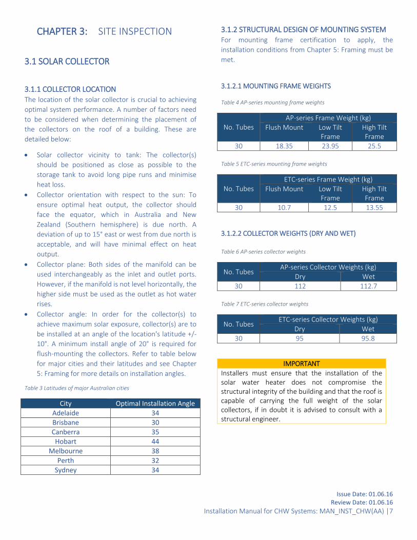
3.1.1 COLLECTOR LOCATION The location of the solar collector is crucial to achieving
optimal system performance. A number of factors need
to be considered when determining the placement of
the collectors on the roof of a building. These are
detailed below:
Solar collector vicinity to tank: The collector(s)
should be positioned as close as possible to the
storage tank to avoid long pipe runs and minimise
heat loss.
Collector orientation with respect to the sun: To
ensure optimal heat output, the collector should
face the equator, which in Australia and New
Zealand (Southern hemisphere) is due north. A
deviation of up to 15° east or west from due north is
acceptable, and will have minimal effect on heat
output.
Collector plane: Both sides of the manifold can be
used interchangeably as the inlet and outlet ports.
However, if the manifold is not level horizontally, the
higher side must be used as the outlet as hot water
rises.
Collector angle: In order for the collector(s) to
achieve maximum solar exposure, collector(s) are to
be installed at an angle of the location's latitude +/-
10°. A minimum install angle of 20° is required for
flush-mounting the collectors. Refer to table below
for major cities and their latitudes and see Chapter
5: Framing for more details on installation angles.
Table 3 Latitudes of major Australian cities
City Optimal Installation Angle
Adelaide 34
Brisbane 30
Canberra 35
Hobart 44
Melbourne 38
Perth 32
Sydney 34
3.1.2 STRUCTURAL DESIGN OF MOUNTING SYSTEM For mounting frame certification to apply, the
installation conditions from Chapter 5: Framing must be
met.
3.1.2.1 MOUNTING FRAME WEIGHTS Table 4 AP-series mounting frame weights
No. Tubes AP-series Frame Weight (kg)
Flush Mount Low Tilt Frame
High Tilt Frame
30 18.35 23.95 25.5
Table 5 ETC-series mounting frame weights
No. Tubes ETC-series Frame Weight (kg)
Flush Mount Low Tilt Frame
High Tilt Frame
30 10.7 12.5 13.55
3.1.2.2 COLLECTOR WEIGHTS (DRY AND WET)
Table 6 AP-series collector weights
No. Tubes AP-series Collector Weights (kg)
Dry Wet
30 112 112.7
Table 7 ETC-series collector weights
No. Tubes ETC-series Collector Weights (kg)
Dry Wet
30 95 95.8
IMPORTANT
Installers must ensure that the installation of the solar water heater does not compromise the structural integrity of the building and that the roof is capable of carrying the full weight of the solar collectors, if in doubt it is advised to consult with a structural engineer.

Issue Date: 01.06.16 Review Date: 01.06.16
Installation Manual for CHW Systems: MAN_INST_CHW(AA) |8
3.1.3 EDGE EXCLUSION ZONES As per AS/NZS 1170.2:2011, the flush-mounted and tilt-
mounted frame systems need to be installed within the
internal roof zone. The edge exclusion zones are
calculated from the minimum of 0.2x'D' (width of the
building), 0.2x'B' (length of the building) and 'H' (average
height of the building).
Figure 1 Edge exclusion zones
3.1.4 ROOF SPACE AND COLLECTOR SHADING When placing the collector(s) on the roof, take into
account the maximum area required for a single Apricus
collector. Refer to the tables below for these values.
Table 8 Coverage of single AP-series collector
Collector (Tubes)
Width (mm) Length (mm) Area (m²)
30 2240 2025 4.5
Table 9 Coverage of single ETC-series collector
Collector (Tubes)
Width (mm) Length (mm) Area (m²)
30 2196 2005 4.4
Shading is another factor that needs to be taken into account. It is recommended that shading from nearby objects, buildings or trees are avoided to optimize the amount of sun the collector receives.
3.2 STORAGE TANK LOCATION The storage tanks are able to be installed indoors or
outdoors.
The storage tanks are to be installed at ground or
floor level and must stand vertically upright as the
manufacturer has intended.
The storage tank should be located as close as
possible to the most frequent draw off points in the
building such as the bathroom or kitchen. If the
storage tank is located a long way from hot water
draw points, a hot water circulation loop on a timer
may be considered to reduce the time-lag for water
to heat up and resultant water wastage.
Consideration should be given to the location of the
storage tank respective to the auxiliary boosting
where applicable.
The tank should not obstruct any windows, doors or
exits and should cause minimal intrusion to the
existing site. Clearances must be allowed for to
make servicing and maintenance convenient without
the need for ladder or scaffold. For servicing, the
PTRV must also be easily accessible.
For glass-lined tanks, consider the positioning of the
tank to allow room for anode removal and
replacement maintenance.
The storage tank must be installed in a properly
drained safe tray where leakage may otherwise
cause damage. The installation of the storage tank
and safe tray must comply with AS/NZS 3500.4 and
all local codes and regulatory authority
requirements with regards to its construction,
installation and draining. Tanks installed outside
must be installed on a suitable concrete slab.
The tank label must be clearly visible.
3.3 TRANSPORTATION AND UNPACKING
3.3.1 TRANSPORTATION OF COMPONENTS
When transporting boxes, note the orientation of
the "THIS WAY UP" arrows.
Ensure all boxes are strapped and secured to
prevent movement during transit.
All tanks must be transported upright. Stacking is not
recommended for any tanks.
Products should always be handled with care.
Damage incurred during the transportation is not
covered under product warranty.
Issue Date: 01.06.16 Review Date: 01.06.16
Installation Manual for CHW Systems: MAN_INST_CHW(AA) |9
3.3.2 UNPACKING OF COMPONENTS
When unpacking, take care to ensure that the
components are not damaged in the process.
Avoid using sharp blades or knives as this can scratch
the surfaces of the products particularly the
evacuated tubes and tanks.
For evacuated tubes and heat pipes, tear open both
ends of the box(es) to allow inspection of the
vacuum at the bottom and for the heat pipes to be
exposed for the application of heat transfer paste.
3.4 OTHER COMPONENTS
3.4.1 GAS HEATER LOCATION (IF APPLICABLE) The gas heater(s) must be installed over a properly
drained safe tray where leakage may cause damage. The
installation of the water heater and safe tray must
comply with AS/NZS 3500.4 and all local codes and
regulatory authority requirements with regards to its
construction, installation and draining.

Issue Date: 01.06.16 Review Date: 01.06.16
Installation Manual for CHW Systems: MAN_INST_CHW(AA) |10
CHAPTER 4: COMPONENT
INSPECTION
4.1 COMPONENTS PROVIDED BY APRICUS
WITH THE SYSTEM Upon receiving the system prior to installation, check
that the following components have been provided. Any
concerns must be brought to the attention of Apricus
immediately.
4.1.1 MANIFOLD
Ensure that the manifold inlet and outlets show no
signs of damage.
Ensure that the correct brassware is provided. For
each bank of n collectors, there will be provided a
minimum of two straight fittings, and n-1
connectors. Note that a bank contains maximum of
five collectors.
4.1.2 TUBES & HEAT PIPES
Ensure that the evacuated tubes are all intact, the
bottom of each tube should be silver. If a tube has a
white or clear bottom, it has lost its vacuum and
should be replaced. In this case, the heat pipe
should be removed and inserted into the
replacement tube.
The evacuated tubes have rubber tube caps on the
end. These are to protect the bottom tip of the glass
tube from being broken.
Heat pipes are bright and shiny when newly
manufactured, but will dull and may form dark grey
surface discoloration over time. This is due to mild
surface oxidation (when exposed to air) and does
not affect the heat pipe's operation.
Do not remove and/or expose the tubes to sunlight
until ready to install, otherwise the heat pipe tip will
become very hot, sufficient to cause serious skin
burns. Note: The outer glass surface will not become
hot.
WARNING
NEVER touch the inside of the evacuated tube or heat pipe tip after exposure to sunlight. WEAR thick leather gloves if handling the heat pipe. WEAR safety glasses at ALL times when handling the glass tubes.
4.1.3 FLUSH MOUNT FRAME
Ensure that all necessary components required
for installation have been received in the packaging.
Refer to Chapter 5: Framing.
4.1.4 SOLAR STORAGE TANK(S) AND PTRV
Ensure the tank(s) is/are accompanied by an
appropriate PTRV.
4.1.5 ANCILLARIES Ancillaries that are required for a solar CHW system
include:
Circulation pump and unions
Controller and sensor leads
4.1.6 GAS SYSTEM: GAS BOOSTER
Ensure the gas booster shows no signs of damage.
4.1.7 GAS SYSTEM: GAS BUFFER TANK(S) AND PTRV
Ensure the tank(s) is/are accompanied by an
appropriate PTRV.
4.1.8 ELECTRIC SYSTEM: HD ELECTRIC TANKS AND
PTRV
Ensure the tank(s) is/are accompanied by an
appropriate PTRV.
Ensure that it has the appropriate number of
elements and rating.
4.2 NECESSARY COMPONENTS Ensure that the following components have been
sourced for the installation. These are not provided as a

Issue Date: 01.06.16 Review Date: 01.06.16
Installation Manual for CHW Systems: MAN_INST_CHW(AA) |11
standard with the system and must be sourced from
others.
Duo valve
Cold water expansion control valve (mandatory in
certain states)
Pressure reducing valve
Four way cross
Check valve
Flow meter
4.3 OTHER COMPONENTS Other components that may be required for installation
that must be sourced from others include:
Three way ball valve for solar return line drain.
Tempering valve solar rated (if applicable)
There may be additional parts or materials required by
plumbers/installers for installation not listed here.

Issue Date: 01.06.16 Review Date: 01.06.16
Installation Manual for CHW Systems: MAN_INST_CHW(AA) |12
CHAPTER 5: FRAMING
5.1 FRAMING OPTIONS There are four easy to install mounting options:
Flush mounted with roof rail, suitable for tin roofs
Flush mounted with roof straps, suitable for tiled
roofs
Low angle tilt, 30o, and
High angle tilt, 45o.
Refer to the sections below for more detail on the AP-
series and ETC-series frames.
5.2 AP-SERIES MOUNTING FRAMES
5.2.1 FLUSH MOUNT FRAME (AP-SERIES) The figure below shows a standard AP-series flush
mounted frame suitable for use in all wind regions with:
5 x Tracks and 5 x L-bracket packs.
Figure 2 Flush mount frame at 1800 mm spacing with 5 tracks
5.2.2 TILT MOUNT FRAME (AP-SERIES) The figure below shows a typical AP-series cyclonic wind
region C frame with: 5 x tracks and 5 x Rear Legs.
Figure 3 Tilt-mount frame at 1800 mm spacing with 5 tracks
5.2.3 INSTALLATION CONDITIONS The AP series frames are suitable to use in Australian
wind regions A, B, C and D, subject to a set of conditional
requirements.
Under these requirements these systems are certified to
Australian Standards AS/NZS 1170.2:2011 Structural
Design Actions Part 2: Wind Actions. Check with your
local building authority to confirm whether or not this
standard is a regulatory requirement in your region.
5.2.3.1 FRAME FIXTURES (AP-SERIES)
The installer is to provide the fixings for the frame to the
roof, ensuring the fixings are applied in accordance with
the table of fixtures provided below. Holes can easily be
drilled into the extruded aluminium components. They
are to be no larger than ø10 mm and not closer than 30
mm center to center.
Note for the tables below showing the number of
fixtures required; ‘FT’ is an abbreviation for Front Track,
‘TB’ for Timber Batten, and ‘SB’ for Steel Batten.
Table 10 Number of screw fixings required per front track (on each end), on the front and rear roof rails for Flush Mounted frames.
No. Tubes
Wind Regions
A B C D No. FT
TB SB No. FT
TB SB No. FT
TB SB No. FT
TB SB
30 3 2 2 3 2 2 5 2 4 5 2 4
Table 11 Number of screw fixings required per rear leg, on the rear roof rail for Tilt Mounted frames.
No. Tubes
Wind Regions
A B C

Issue Date: 01.06.16 Review Date: 01.06.16
Installation Manual for CHW Systems: MAN_INST_CHW(AA) |13
No. FT
TB SB No. FT
TB SB No. FT
TB SB
30 3 4 4 5 4 4 5 4 8
Additionally, for tilt mounted frame systems, there are
two screws required per front track for the front roof
rail.
WARNING
DO NOT use power tools or long shafted tools that may over-torque the bolts (as stainless steel bolts are susceptible to galling/locking). Tighten frame bolts with spanners or short shafted socket wrenches only.
Bolt assemblies come with spring washers to maintain
long-term tension.
The AP series frame systems come pre-packaged to
ensure the most streamlined and simple assembly
process. Follow the assembly instructions provided with
the frame.
5.2.3.2 ROOF FIXING GUIDE (AP-SERIES)
To proceed with attaching the mounting frame to the
roof, follow all fixing rules as per the Installation
conditions (for certification to apply).
Batten/Purlin Spacing is to be 600, 900, 1500 or
1800mm.
Batten/Purlin Screws are to be installed as follows:
Timber Battens/Purlins: 14G Ø6.3mm timber screw,
with minimum 35mm embedment into battens.
Minimum joint group J4.
Steel Battens/Purlins: 14G Ø6.3mm tek screw.
Minimum steel thickness 0.75mm, Grade G550.
There is an even number of screws per roof rail, so
fixing points should be equidistant from the roof rail.
This will ensure that the wind loads are equally
distributed across the roof rail. Line up the roof rails
with battens accordingly. For tilt-mount systems the
batten/purlin spacing can be increased where the
angle of the tilt decreases. Table 10 and Table 11
show the number of screws required per frame for a
flush mounted and a tilt mounted frame
respectively.
Figure 4 Roof fixing locations 1800 mm
Note that Battens and purlins are the same components
and are usually located horizontal, or perpendicular to
the roof pitch. This differs from rafters which are
situated parallel to the roof pitch.
Maximum average building height of install: 10m above
ground.
Flush Mount: roof pitch needs to be 20-45o to the
horizontal.
Tilt Mount: roof pitch needs to be 0-10o to the
horizontal. For efficient heat transfer of the evacuated
tubes they should be installed at a minimum overall
pitch of 20o.
Regions A and B: Maximum tilt angle 45o to the
horizontal
Region C: Maximum tilt angle 30o to the
horizontal
Existing roof check: the structural adequacy of
supporting roof members must be confirmed by a
practicing structural engineer prior to all installations
unless a roof rail is used for every batten location.
IMPORTANT
Ensure all roof penetrations are watertight.
Use the following examples as a guide for installation for
different roof types.
5.2.3.3 TIN ROOF INSTALLATION (AP-SERIES)
For corrugated/tin roofs, place fixings on the peak of the
roofing sheet material to minimise the risk of leaks.
Fixings are to be screwed into the batten with minimum
35 mm embedment.

Issue Date: 01.06.16 Review Date: 01.06.16
Installation Manual for CHW Systems: MAN_INST_CHW(AA) |14
Figure 5 35 mm embedment into the batten/purlin [rear view]
5.2.3.4 TILED ROOF INSTALLATION (AP-SERIES)
For tiled roofs (where drilling is undesirable) use Apricus
roof straps to attach the frame to the battens/purlins.
Roof straps can also be attached to roof rails by drilling
through them.
IMPORTANT
Tilt mount frame systems installed on tiled roofs are not certified under AS/NZS 1170.2.
Figure 6 Roof attachment strap example
5.2.3.5 ADJUSTING TILT MOUNT ANGLE
When installing tilt-mount systems, the mounting frame
can be modified to achieve a reduced tilt angle. This
would be preferable where the optimal tilt angle is not
achievable for the given roof pitch and tilt leg.
To reduce the installation angle of the collectors, the
aluminium legs should be cut to a reduced length and a
new hole should be drilled to allow for securing. By
reducing the length of the aluminium tilt leg, the frame
is brought closer to the roof and the angle is reduced.
The total pitch of the collectors should not be reduced
below 20o.
Note that decreasing the tilt angle will consequently
decrease the wind loading on the system and as such
will not impact the structural integrity of the system.

Issue Date: 01.06.16 Review Date: 01.06.16
Installation Manual for CHW Systems: MAN_INST_CHW(AA) |15
5.3 ETC-SERIES MOUNTING FRAMES
5.3.1 FLUSH MOUNT FRAME (ETC-SERIES) The figure below shows a standard flush mount frame
suitable for use in all wind regions with: 2x front tracks.
Note the image also shows the roof rails and bottom
track.
Figure 7 ETC series Flush mount frame
5.3.2 TILT MOUNT FRAME (ETC-SERIES) The figure below shows the tilt frame configuration for
use in all wind regions: 2x front tracks and 2x Rear Legs.
Note the image below also shows the roof rails and X
brace.
Figure 8 ETC series Tilt-mount frame
5.3.3 INSTALLATION CONDITIONS (ETC-SERIES) All variations of the ETC series frames are cyclone rated,
suitable to use in Australian wind regions A, B, C and D.
Under these requirements these systems are certified to
Australian Standards AS/NZS 1170.2:2011 Structural
Design Actions Part 2: Wind Actions. Check with your
local building authority to confirm whether or not this
standard is a regulatory requirement in your region.
5.3.3.1 FRAME FIXTURES (ETC-SERIES)
The installer is to provide the fixings for the frame to the
roof, ensuring the fixings are applied in accordance with
the table of fixtures provided below. Holes can easily be
drilled into the extruded aluminium components. They
are to be no larger than ø10 mm and not closer than
30mm center to center.
Note for the tables below showing the number of
fixtures required; ‘TB’ is an abbreviation for Timber
Batten, and ‘SB’ for Steel Batten.
Table 12 Number of screw fixings required per front track (on each end), on the front and rear roof rails for Flush Mounted frames.
No. Tubes
Wind Regions
A B C D
TB SB TB SB TB SB TB SB
30 2 2 2 2 2 2 2 2
Table 13 Number of screw fixings required per front track, on the front roof rail for Tilt Mounted frames.
No. Tubes
Wind Regions
A B C D
TB SB TB SB TB SB TB SB
30 2 2 2 2 2 2 N/A N/A
Table 14 Number of screw fixings required per rear leg, on the rear roof rail for Tilt Mounted frames.
No. Tubes
Wind Regions
A B C D
TB SB TB SB TB SB TB SB
30 2 2 2 2 2 4 N/A N/A

Issue Date: 01.06.16 Review Date: 01.06.16
Installation Manual for CHW Systems: MAN_INST_CHW(AA) |16
WARNING
DO NOT use power tools or long shafted tools that may over-torque the bolts (as stainless steel bolts are susceptible to galling/locking). Tighten frame bolts with spanners or short shafted socket wrenches only.
Bolt assemblies come with spring washers to maintain
long-term tension.
The ETC series frame systems come pre-packaged to
ensure the most streamlined and simple assembly
process. Follow the assembly instructions provided with
the frame.
5.3.3.2 ROOF FIXING GUIDE (ETC SERIES)
To proceed with attaching the mounting frame to the
roof, follow all fixing rules as per the Installation
Conditions provided below (for certification to apply).
Batten/Purlin Spacing is to be 600, 900, 1500 or
1800mm.
Batten/Purlin Screws are to be installed as follows:
Timber Battens/Purlins: 14G Ø6.3mm timber screw,
with minimum 35mm embedment into battens.
Minimum joint group J4.
Steel Battens/Purlins: 14G Ø6.3mm tek screw.
Minimum steel thickness 0.75mm, Grade G550.
There is an even number of screws per roof rail, so
fixing points should be equidistant from the roof rail.
This will ensure that the wind loads are equally
distributed across the roof rail. Line up the roof rails
with battens accordingly. For tilt-mount systems the
batten/purlin spacing can be increased where the
angle of the tilt decreases.
Table 12 to Table 14 show the number of screws
required per frame for flush mounted and tilt
mounted frames respectively.
Note that Battens and purlins are the same components
and are usually located horizontal, or perpendicular to
the roof pitch. This differs from rafters which are
situated parallel to the roof pitch.
Maximum average building height of install: 15m above
ground.
Flush Mount: roof pitch needs to be 0-30o to the
horizontal. Although the wind loading conditions allow
for a horizontal pitch at 0o, for efficient heat transfer of
the evacuated tubes they should be installed at a
minimum overall pitch of 20o.
Tilt Mount: roof pitch needs to be 0-20o to the
horizontal.
Regions A, B, C and D: the maximum tilt angle is
45o to the horizontal.
Existing roof check: the structural adequacy of
supporting roof members must be confirmed by a
practicing structural engineer prior to all installations.
IMPORTANT
Ensure all roof penetrations are watertight.
Use the following examples as a guide for installation for
different roof types.
5.3.3.3 TIN ROOF INSTALLATION (ETC-SERIES)
For corrugated/tin roofs, place fixings on the peak of the
roofing sheet material to minimise the risk of leaks.
Fixings are to be screwed into the batten with minimum
35mm embedment. Refer to Figure 5.
Figure 9 Close-up of front track connection to roof rail, and fixings on peaks of tin roof equidistant from front track.
5.3.3.4 TILED ROOF INSTALLATION (ETC SERIES)
For tiled roofs (where drilling is undesirable) use Apricus
roof straps to attach the frame to the battens/purlins.

Issue Date: 01.06.16 Review Date: 01.06.16
Installation Manual for CHW Systems: MAN_INST_CHW(AA) |17
Roof straps can also be attached to roof rails by drilling
through them. Refer to Figure 6.
IMPORTANT
Tilt mount frame systems installed on tiled roofs are not certified under AS/NZS 1170.2.
5.3.3.5 ADJUSTING TILT MOUNT ANGLE
When installing tilt-mount systems, the mounting frame
can be modified to achieve a reduced tilt angle. This
would be preferable where the optimal tilt angle is not
achievable for the given roof pitch and tilt leg.
To reduce the installation angle of the collectors, the
aluminium legs should be cut to a reduced length and a
new hole should be drilled to allow for securing. By
reducing the length of the aluminium tilt leg, the frame
is brought closer to the roof and the angle is reduced.
The total pitch of the collectors should not be reduced
below 20o.
Note that decreasing the tilt angle will consequently
decrease the wind loading on the system and as such
will not impact the structural integrity of the system.

Issue Date: 01.06.16 Review Date: 01.06.16
Installation Manual for CHW Systems: MAN_INST_CHW(AA) |18
CHAPTER 6: SYSTEM PLUMBING
6.1 SYSTEM LAYOUT The system components that are a part of a typical
electric and gas solar hot water systems are depicted in
the system schematics in Figure 19 and Figure 20Error!
eference source not found. in Chapter 10: Appendix,
respectively.
See Table 15Error! Reference source not found. and
Table 16 below for the corresponding numbered
components to the schematics for electric and gas
systems respectively.
Table 15 Components that make up a typical Electric boosted solar hot water system.
No. Component Function 1 Evacuated
tube collector(s)
Solar energy collection
2 Circulation Pump(s)
Circulates water from the solar storage tank(s) to the collectors(s)
3 Controller Monitors temperatures and controls the system
4 Expansion Tank(s)
Allows the system to “breathe” when pressure increases in the system (Optional)
5 Solar Storage Tank(s)
Stores solar hot water
6 PTRV Pressure Temperature Relief Valve
7 Ring Main Pump(s)
Recirculates water back from the ring main into the auxiliary heater.
8 Heavy duty (HD) electric storage water heater(s)
Provides the auxiliary backup energy source for cloudy days and legionella protection.
Table 16 Components that make up a typical Gas boosted solar hot water system
No. Component Function 1 Evacuated
tube collector(s)
Solar energy collection
2 Circulation Pump(s)
Circulates water from the tank to the manifold
3 Controller Monitors temperatures and controls the system
4 Expansion Tank(s)
Allows the system to “breathe” when pressure increases in the system (Optional)
5 Solar Storage Tank(s)
Stores solar hot water
6 PTRV on each tank
Pressure Temperature Relief Valve
7 Ring Main Pump(s)
Recirculates water back from the ring main into the auxiliary heater.
8 Gas Recirculation Pump(s)
Circulates water from the inlet of the buffer tank into the auxiliary heater.
9 Buffer tank(s) Provides storage to increase the first hour delivery litres.
10 Gas Heater(s) Provides a backup energy source for cloudy days and legionella protection
6.2 PIPING
6.2.1 PIPE MATERIAL AND PIPE SIZE For solar CHW system installations, the recommended
pipe is copper and the size is variable depending on the
system design. Only qualified or competent persons are
to size the piping for each specific commercial
application.
Factors affecting the choice of pipe sizing include the
flow rate and pressure drop. These two factors are
closely related; a higher pressure drop will reduce the
flow rate. Pressure drop increases with decreased pipe
diameters as well as the presence of bends, elbows and
other components that restrict flow.
It may be necessary for some installations with
numerous pipe bends and significant pipe runs to
increase the pipe diameter to reduce the pressure drop.
All pipe work must be installed in accordance with
AS/NZS 3500.4.
IMPORTANT
It is necessary that all valves, fittings and piping connections used are solar rated and are able to withstand temperatures of up to 220oC.
6.2.2 PIPE INSULATION Insulate all pipes running to and from the manifold with
insulation of at least 15mm thickness, or 25mm in cold

Issue Date: 01.06.16 Review Date: 01.06.16
Installation Manual for CHW Systems: MAN_INST_CHW(AA) |19
climates. Also, ensure the insulation is tight against the
all ports (minimizing the loss of heat from any exposed
areas). As with solar CHW systems the pipe sizes and
lengths can vary from application to application, the pipe
insulation may as well. A qualified plumber must
determine the appropriate insulation required.
IMPORTANT
All insulation needs to be solar-rated. Any insulation exposed to sunlight must be UV-stabilized.
6.3 STORAGE TANK
6.3.1 COMMERCIAL GLASS-LINED STORAGE TANK The Apricus 400L Glass-lined storage tank contains seven
ports, and is typically used as solar storage and/or as gas
buffer tanks. Note that when this tank is used as a gas
buffer tank, the unused ports are plugged.
1. Inlet (Mains): Inlet line from mains water supply
2. Solar Flow: Flow line to the collector
3. Solar Return: Return line from the collector
4. Outlet: Outlet line to tempering valve and load
5. Sensor 1 Port: Bottom temperature sensor
6. Sensor 2 Port: Top temperature sensor
7. PTRV: Pressure temperature relief valve location
Figure 10 Commercial 400L Glass-Lined Storage Tank
The inlet and outlet ports on this tank are 40mm (1.5”)
BSP, while the remaining ports are of 20mm (3/4”) BSP.
Teflon tape must be used to seal any fitting. Copper
olives must be used with all compression fittings.
IMPORTANT
Apricus tanks must be installed in accordance to AS/NZS 3500.4 as well as any other relevant local/government standards.
6.3.1.1 INLET (MAINS)
The mains line should consist of the following brass
components when installing:
Duo valve
Cold Water ECV
Pressure Reducing Valve

Issue Date: 01.06.16 Review Date: 01.06.16
Installation Manual for CHW Systems: MAN_INST_CHW(AA) |20
Four-Way Cross
Figure 11 Mains Line Valves
The set of mains line valves can be purchased as a kit
from Apricus and provides the above components with
insulating jackets to streamline the installation process.
IMPORTANT
Where applicable, the tempering valve must be the last downstream component installed before the hot water reaches the hot water fixtures.
6.3.1.2 SOLAR FLOW
This port is used for the water line directed up to the
solar collectors to be heated. This line consists of the
following components in order from closest to furthest
away:
Circulation Pump
Flow meter
Check valve
Collectors
6.3.1.3 SOLAR RETURN
This port is used for the water line returning from the
solar collectors after being heated. This line does not
require any additional components, but should be run as
short as possible and have continuous fall back to the
solar return port.
Apricus recommends using a three way ball valve and
drain on the solar return line to allow convenient system
filling and draining.
On the solar return line near the tank port, it is
recommended to include a U-shaped heat trap with an
approximate 25cm dip in the piping configuration to
prevent reverse thermos-siphoning.
6.3.1.4 OUTLET
The outlet is where the hot water from the tank is
extracted to be supplied to the auxiliary heaters before
supply to the commercial application fixtures.
6.3.1.5 SENSOR PORTS
The sensors must be coated with heat transfer paste and
inserted through the cable gland into the appropriate
sensor port and tightened.
The first temperature sensor port is located on either
side of the collector manifold. Sensor 1 (S1) must be
connected to the outlet of the manifold (the higher
side). The top sensor port houses S3 and the bottom
sensor port houses S2.
Depending on the complexity of functions required for
the commercial application, the controller will vary. All
controllers will need to have the temperature
differential function to control the solar circulation
pump. The controller will require three sensor leads to
be installed into the appropriate sensor ports in the solar
system. Additional temperature sensors may be used for
other functions or to monitor temperatures across the
system.
6.3.1.6 PTRV PORT
The PTRV port is where the tank ‘pressure and
temperature relief valve’ is to be installed. All PTRV’s
must be fitted with a copper drain pipe to carry any
discharge to an appropriate drain.
IMPORTANT
All storage tanks include a PTRV, which is located in the vertical column or element cover.

Issue Date: 01.06.16 Review Date: 01.06.16
Installation Manual for CHW Systems: MAN_INST_CHW(AA) |21
6.4 SOLAR COLLECTORS
6.4.1 BANKS OF COLLECTORS It is recommended that a maximum of five collectors are
installed in series. It is possible to have multiple banks of
three to five collectors to achieve larger collector
combination arrays.
Note that the solar collectors are to be installed in
reverse return unless balancing valves are installed
(sourced by others). This is important as the heat
transfer rate is dependent on the flow rate. If the flow
rate is unequal there will be uneven heating, this means
you will not get the most out of your system.
IMPORTANT
Poor design of collector pipe runs will result in sub-optimal operation of the solar collectors. This will lead to uneven thermal cycling of your collectors. The result is reduced solar yield and potential reduction of system.
6.4.2 BRASSWARE The commercial solar manifolds require appropriate
brassware to be used for plumbing.
In order to connect collectors in series, you must use a
connector brass nipple (both flared ends ¾”). See Figure
12.
Figure 12 Connector brass nipple being used to connect one manifold with another manifold in series.
In order to connect a collector to solar flow or solar
return piping, a straight flared brass nipple (a flared end
¾” and ¾”MBSP) must be connected to the manifold
inlet/outlet. Once this is done, the copper piping can be
connected to the inlet/outlet. See Figure 13.
Figure 13 Straight flared ¾” brass nipple connection to manifold inlet/outlet.

Issue Date: 01.06.16 Review Date: 01.06.16
Installation Manual for CHW Systems: MAN_INST_CHW(AA) |22
CHAPTER 7: COMMISSIONING
7.1 SYSTEM FILLING AND AIR PURGE After all the plumbing connections to the solar collector
have been made, the solar hot water system needs to be
filled with water and the collector loop purged of air.
This should be completed prior to insertion of evacuated
tubes and connection of the tank to the hot water load.
To fill the system:
1. Open the cold mains line and fill up the tank and
open the hot water outlet or hot water taps.
2. Turn the pump dial to speed 3 and connect it
directly to the electricity mains rather than the
controller.
3. Open up an outlet to drain the solar return line.
4. Close the drain when filling is completed, this is
indicated by a constant stream of water exiting from
the solar return line.
If constant flow is not achieved, closing and opening
the duo valve can force air back into the tank to be
relieved at hot water fixtures.
5. Set the pump back to speed 1 and reconnect the
pump to the controller.
7.2 CONTROLLER 1. Connect all sensor leads to the appropriate ports in
the tank and manifold.
2. Plug in the controller power adaptor to the wall
socket and ensure all sensor leads are connected to
the correct sensor ports.
3. Test for water leaks around the pipe works and
brassware.
4. Check that all temperature readings on the
controller are functioning with the parameters of
the product.
7.3 FLOW METER SETTINGS The flow rate of the system network should be checked
after installation to ensure suitable conditions are met.
The table below shows the maximum flow rate settings
for Apricus collectors.
Table 17 Maximum and suggested flow rate requirements
Collector (Tubes)
Maximum Flow Rate (L/min)
Suggested Flow Rate (L/min)
30 2 1.25
7.4 SOLAR COLLECTORS
7.4.1 FRAMES Refer to the Frame Assembly Guide provided with the
frame.
1. Assemble the frame according to the relevant frame
assembly guide.
2. Align the roof rails of the completed frame with the
batten/purlin on the roof.
3. Drill holes through the roof rails and secure the
frame to the roof using suitable screws. Number of
fixtures required can be found in Chapter 5:
Framing.
4. Mount the manifold onto the front tracks, ensuring
alignment with bottom track.
5. Ensure that the attachment plate sits in the front
groove of the manifold and the rear attachment
plates sit in the rear groove.
After installation of the frame and manifold, return to
complete the plumbing of the system, tank and pump
station.
WARNING
DO NOT insert the evacuated tubes into the manifold until the system has been filled with water and all other steps are complete.
7.4.2 PIPING AND SENSOR CONNECTION Refer to the Basic Installation Guide provided with the
manifold.
1. Insert the sensor into the sensor port on manifold.
2. Connect the brass fitting on the manifold
inlet/outlet.
3. Piping insulation will need to be done all the way up
to the manifold.

Issue Date: 01.06.16 Review Date: 01.06.16
Installation Manual for CHW Systems: MAN_INST_CHW(AA) |23
7.4.3 EVACUATED TUBES AND HEAT PIPES Refer to the Basic Installation Guide provided with the
manifold.
1. If weather conditions are dusty, take care to ensure
heat paste is not contaminated with impurities, as
this may reduce thermal conductivity and efficiency
of the heat paste. If weather conditions are wet,
take care to ensure water does not enter the inside
of the evacuated tube.
2. Open the evacuated tube box on the side with the
heat pipes.
3. Pull the heat pipe out ~10cm and ensure to keep the
rest of the tube shaded.
Figure 14 Heat pipe exposed
4. Coat the heat pipe bulb with heat transfer paste;
this can be applied using a piece of foam insulation.
5. Take the evacuated tube from the box and guide the
heat pipe into the inside of the header port.
Figure 15 Guiding heat pipe into manifold
6. Push the heat pipe in full depth.
Figure 16 Pushing heat pipe into manifold
7. Use a damp cloth to lubricate the outer surface of
the evacuated tube and the rubber ring in the
manifold to minimize friction during insertion.
8. Insert the evacuated tube using a slight twist and
pushing action.
Figure 17 Inserting tube into manifold
9. Repeat steps 2-6 for the remainder of the tubes and
collectors.
10. Using provided tube clips, secure the evacuated
tubes into the bottom track of the frame. Always
secure each tube clip before installed the next tube.
11. Wipe down each evacuated tube with a damp cloth
to ensure a polished and clean installation.
7.5 OTHER SYSTEM COMPONENTS
7.5.1 EXPANSION TANK Expansion tanks should always be installed downstream
of a non-return valve. This ensures that water is able to
flow into it from both directions. If it were installed
upstream, it would only function for half of the system
and could cause significant damage to the unprotected
side.

Issue Date: 01.06.16 Review Date: 01.06.16
Installation Manual for CHW Systems: MAN_INST_CHW(AA) |24
Figure 18 Diagram showing the expansion tank relative to the non-return valve

Issue Date: 01.06.16 Review Date: 01.06.16
Installation Manual for CHW Systems: MAN_INST_CHW(AA) |25
CHAPTER 8: AUXILIARY HEATING
8.1 BOOSTING EXPLAINED If the solar contribution during the day is not enough to
raise the water to a suitable temperature the auxiliary
booster can provide additional heating. During
sufficiently sunny weather, the solar collectors, when
sized appropriately, will normally be able to offset
significant hot water usage during that period, but
during winter months and overcast days boosting may
be required.
8.1.1 AUXILIARY HEATERS Refer to the relevant specific product installation
manuals for details not covered in this manual
8.3 WATER HEATING REQUIREMENTS It is a legal requirement that water be heated on a
regular basis to kill Legionella bacteria that can lead to
Legionnaires disease. The minimum heat requirements
are in the table below.
Table 18 Minimum Heat Requirements
Type of Apricus System Installed
Minimum Heat Requirements
Gas Boosted Systems
70°C boost if less than 55°C each time water is used
Glass-lined Bottom element electric boosted system
Once per week to 60°C for 32 minutes
Mid element electric boosted system Once per day to 60°C

Issue Date: 01.06.16 Review Date: 01.06.16
Installation Manual for CHW Systems: MAN_INST_CHW(AA) |26
CHAPTER 9: POST INSTALLATION To ensure optimal operation and to maintain the
integrity of Apricus solar hot water systems,
commissioning is an essential process. Ensure that each
of the following processes is carried out prior to leaving
the site.
SYSTEM OPERATION CHECK Given good sunlight, the evacuated tubes will begin to
produce heat after a 5-10 minute "warm up" period.
There should be an observable increase in the
temperature reading at the roof sensor on the
controller. When there is an 8°C temperature
differential between ROOF and TANK sensors the
circulation pump should turn on.
After initial completed installation of collector, watch
the operation of the pump and controller for at least 5
ON/OFF cycles or 15 minutes as the system stabilises.
This process may take longer in overcast or cold
conditions.
IMPORTANT
When replacing damaged tubes follow all relevant OH&S policies. Protective clothing is to be worn at all times. WEAR thick leather gloves if handling the heat pipe. WEAR safety glasses at ALL times when handling the glass tubes.
CHECKLIST PRIOR TO LEAVING INSTALLATION SITE
System check: Check all connections for leaks and
that all components are installed as per this manual.
Take photos of all system components for warranty
purposes. This should include photos of the
plumbing lines to and from the tank, collector and
sensor port connections.
Note down the Tank Serial Number
Note down the Apricus System Model Number
Note down the Collector Serial Number
Fill out the installation record form supplied for
system warranty and service issues.
Submit your Installation Record Form via
Email: [email protected]
OR
Online: www.apricus.com.au
Complete the rebate form for the system prior to
leaving the site, this will require the installer’s
signature.

Issue Date: 01.06.16 Review Date: 01.06.16
Installation Manual for CHW Systems: MAN_INST_CHW(AA) |27
CHAPTER 10: APPENDIX
Figure 19 Typical Gas boosted solar CHW system.

Issue Date: 01.06.16 Review Date: 01.06.16
Installation Manual for CHW Systems: MAN_INST_CHW(AA) |28
Figure 20 Typical Electric boosted solar CHW system